EP2330280A1 - Procédé de fonctionnement d'une turbine à gaz, système de turbine à gaz, procédé et système pour refroidir un flux d'hydrocarbures - Google Patents
Procédé de fonctionnement d'une turbine à gaz, système de turbine à gaz, procédé et système pour refroidir un flux d'hydrocarbures Download PDFInfo
- Publication number
- EP2330280A1 EP2330280A1 EP09177647A EP09177647A EP2330280A1 EP 2330280 A1 EP2330280 A1 EP 2330280A1 EP 09177647 A EP09177647 A EP 09177647A EP 09177647 A EP09177647 A EP 09177647A EP 2330280 A1 EP2330280 A1 EP 2330280A1
- Authority
- EP
- European Patent Office
- Prior art keywords
- stream
- chilling
- gas turbine
- compressor
- heat
- Prior art date
- Legal status (The legal status is an assumption and is not a legal conclusion. Google has not performed a legal analysis and makes no representation as to the accuracy of the status listed.)
- Withdrawn
Links
- 229930195733 hydrocarbon Natural products 0.000 title claims abstract description 71
- 150000002430 hydrocarbons Chemical class 0.000 title claims abstract description 71
- 239000004215 Carbon black (E152) Substances 0.000 title claims abstract description 65
- 238000001816 cooling Methods 0.000 title claims abstract description 60
- 238000000034 method Methods 0.000 title claims abstract description 34
- 239000007789 gas Substances 0.000 claims abstract description 147
- QVGXLLKOCUKJST-UHFFFAOYSA-N atomic oxygen Chemical compound [O] QVGXLLKOCUKJST-UHFFFAOYSA-N 0.000 claims abstract description 50
- 239000001301 oxygen Substances 0.000 claims abstract description 50
- 229910052760 oxygen Inorganic materials 0.000 claims abstract description 50
- 239000000446 fuel Substances 0.000 claims abstract description 20
- 239000003507 refrigerant Substances 0.000 claims description 107
- 239000012530 fluid Substances 0.000 claims description 59
- 238000002485 combustion reaction Methods 0.000 claims description 22
- 238000011144 upstream manufacturing Methods 0.000 claims description 11
- 239000013529 heat transfer fluid Substances 0.000 claims description 8
- 238000010438 heat treatment Methods 0.000 claims description 4
- 238000006243 chemical reaction Methods 0.000 claims description 2
- 239000002826 coolant Substances 0.000 description 61
- 239000003570 air Substances 0.000 description 57
- VNWKTOKETHGBQD-UHFFFAOYSA-N methane Chemical compound C VNWKTOKETHGBQD-UHFFFAOYSA-N 0.000 description 41
- 239000007788 liquid Substances 0.000 description 28
- XLYOFNOQVPJJNP-UHFFFAOYSA-N water Substances O XLYOFNOQVPJJNP-UHFFFAOYSA-N 0.000 description 16
- 230000006835 compression Effects 0.000 description 12
- 238000007906 compression Methods 0.000 description 12
- QGZKDVFQNNGYKY-UHFFFAOYSA-N Ammonia Chemical group N QGZKDVFQNNGYKY-UHFFFAOYSA-N 0.000 description 11
- ATUOYWHBWRKTHZ-UHFFFAOYSA-N Propane Chemical compound CCC ATUOYWHBWRKTHZ-UHFFFAOYSA-N 0.000 description 11
- 238000010521 absorption reaction Methods 0.000 description 11
- 239000003345 natural gas Substances 0.000 description 11
- AMXOYNBUYSYVKV-UHFFFAOYSA-M lithium bromide Chemical compound [Li+].[Br-] AMXOYNBUYSYVKV-UHFFFAOYSA-M 0.000 description 9
- 238000012546 transfer Methods 0.000 description 9
- IJDNQMDRQITEOD-UHFFFAOYSA-N n-butane Chemical class CCCC IJDNQMDRQITEOD-UHFFFAOYSA-N 0.000 description 7
- 150000003839 salts Chemical class 0.000 description 7
- IJGRMHOSHXDMSA-UHFFFAOYSA-N Atomic nitrogen Chemical compound N#N IJGRMHOSHXDMSA-UHFFFAOYSA-N 0.000 description 6
- 230000008569 process Effects 0.000 description 6
- OTMSDBZUPAUEDD-UHFFFAOYSA-N Ethane Chemical compound CC OTMSDBZUPAUEDD-UHFFFAOYSA-N 0.000 description 5
- 235000013844 butane Nutrition 0.000 description 5
- 239000012141 concentrate Substances 0.000 description 5
- 239000000470 constituent Substances 0.000 description 5
- 239000012071 phase Substances 0.000 description 5
- 239000001294 propane Substances 0.000 description 5
- 238000005194 fractionation Methods 0.000 description 4
- 239000000463 material Substances 0.000 description 4
- 239000000047 product Substances 0.000 description 4
- MYMOFIZGZYHOMD-UHFFFAOYSA-N Dioxygen Chemical compound O=O MYMOFIZGZYHOMD-UHFFFAOYSA-N 0.000 description 3
- UFHFLCQGNIYNRP-UHFFFAOYSA-N Hydrogen Chemical compound [H][H] UFHFLCQGNIYNRP-UHFFFAOYSA-N 0.000 description 3
- 229910021529 ammonia Inorganic materials 0.000 description 3
- 230000008901 benefit Effects 0.000 description 3
- 230000007423 decrease Effects 0.000 description 3
- 238000007710 freezing Methods 0.000 description 3
- 230000008014 freezing Effects 0.000 description 3
- 238000005338 heat storage Methods 0.000 description 3
- 239000000203 mixture Substances 0.000 description 3
- 230000004048 modification Effects 0.000 description 3
- 238000012986 modification Methods 0.000 description 3
- 229910052757 nitrogen Inorganic materials 0.000 description 3
- 230000009467 reduction Effects 0.000 description 3
- 238000005057 refrigeration Methods 0.000 description 3
- 239000000243 solution Substances 0.000 description 3
- NLXLAEXVIDQMFP-UHFFFAOYSA-N Ammonium chloride Substances [NH4+].[Cl-] NLXLAEXVIDQMFP-UHFFFAOYSA-N 0.000 description 2
- VHUUQVKOLVNVRT-UHFFFAOYSA-N Ammonium hydroxide Chemical compound [NH4+].[OH-] VHUUQVKOLVNVRT-UHFFFAOYSA-N 0.000 description 2
- VGGSQFUCUMXWEO-UHFFFAOYSA-N Ethene Chemical compound C=C VGGSQFUCUMXWEO-UHFFFAOYSA-N 0.000 description 2
- 239000005977 Ethylene Substances 0.000 description 2
- LYCAIKOWRPUZTN-UHFFFAOYSA-N Ethylene glycol Chemical compound OCCO LYCAIKOWRPUZTN-UHFFFAOYSA-N 0.000 description 2
- 239000012080 ambient air Substances 0.000 description 2
- 230000015572 biosynthetic process Effects 0.000 description 2
- 239000012267 brine Substances 0.000 description 2
- 238000009833 condensation Methods 0.000 description 2
- 230000005494 condensation Effects 0.000 description 2
- 238000007599 discharging Methods 0.000 description 2
- 230000000694 effects Effects 0.000 description 2
- 230000005611 electricity Effects 0.000 description 2
- 238000001704 evaporation Methods 0.000 description 2
- 230000008020 evaporation Effects 0.000 description 2
- 239000002737 fuel gas Substances 0.000 description 2
- 238000005191 phase separation Methods 0.000 description 2
- 238000010248 power generation Methods 0.000 description 2
- 230000005855 radiation Effects 0.000 description 2
- HPALAKNZSZLMCH-UHFFFAOYSA-M sodium;chloride;hydrate Chemical compound O.[Na+].[Cl-] HPALAKNZSZLMCH-UHFFFAOYSA-M 0.000 description 2
- -1 H2O N2 Chemical class 0.000 description 1
- DGAQECJNVWCQMB-PUAWFVPOSA-M Ilexoside XXIX Chemical compound C[C@@H]1CC[C@@]2(CC[C@@]3(C(=CC[C@H]4[C@]3(CC[C@@H]5[C@@]4(CC[C@@H](C5(C)C)OS(=O)(=O)[O-])C)C)[C@@H]2[C@]1(C)O)C)C(=O)O[C@H]6[C@@H]([C@H]([C@@H]([C@H](O6)CO)O)O)O.[Na+] DGAQECJNVWCQMB-PUAWFVPOSA-M 0.000 description 1
- OFBQJSOFQDEBGM-UHFFFAOYSA-N Pentane Chemical class CCCCC OFBQJSOFQDEBGM-UHFFFAOYSA-N 0.000 description 1
- NINIDFKCEFEMDL-UHFFFAOYSA-N Sulfur Chemical class [S] NINIDFKCEFEMDL-UHFFFAOYSA-N 0.000 description 1
- 150000004945 aromatic hydrocarbons Chemical class 0.000 description 1
- 239000003245 coal Substances 0.000 description 1
- 238000004891 communication Methods 0.000 description 1
- 238000010276 construction Methods 0.000 description 1
- 238000005260 corrosion Methods 0.000 description 1
- 230000007797 corrosion Effects 0.000 description 1
- 238000013461 design Methods 0.000 description 1
- 238000000605 extraction Methods 0.000 description 1
- 239000003517 fume Substances 0.000 description 1
- 239000011521 glass Substances 0.000 description 1
- WGCNASOHLSPBMP-UHFFFAOYSA-N hydroxyacetaldehyde Natural products OCC=O WGCNASOHLSPBMP-UHFFFAOYSA-N 0.000 description 1
- 239000003112 inhibitor Substances 0.000 description 1
- 238000002347 injection Methods 0.000 description 1
- 239000007924 injection Substances 0.000 description 1
- 230000010354 integration Effects 0.000 description 1
- 239000007791 liquid phase Substances 0.000 description 1
- 230000007246 mechanism Effects 0.000 description 1
- 230000001590 oxidative effect Effects 0.000 description 1
- 239000003208 petroleum Substances 0.000 description 1
- 238000002203 pretreatment Methods 0.000 description 1
- QQONPFPTGQHPMA-UHFFFAOYSA-N propylene Natural products CC=C QQONPFPTGQHPMA-UHFFFAOYSA-N 0.000 description 1
- 125000004805 propylene group Chemical group [H]C([H])([H])C([H])([*:1])C([H])([H])[*:2] 0.000 description 1
- 238000011084 recovery Methods 0.000 description 1
- 238000010992 reflux Methods 0.000 description 1
- 238000004088 simulation Methods 0.000 description 1
- 229910052708 sodium Inorganic materials 0.000 description 1
- 239000011734 sodium Substances 0.000 description 1
- 238000001179 sorption measurement Methods 0.000 description 1
- 239000013589 supplement Substances 0.000 description 1
- 125000000383 tetramethylene group Chemical group [H]C([H])([*:1])C([H])([H])C([H])([H])C([H])([H])[*:2] 0.000 description 1
- 239000002918 waste heat Substances 0.000 description 1
Images


Classifications
-
- F—MECHANICAL ENGINEERING; LIGHTING; HEATING; WEAPONS; BLASTING
- F02—COMBUSTION ENGINES; HOT-GAS OR COMBUSTION-PRODUCT ENGINE PLANTS
- F02C—GAS-TURBINE PLANTS; AIR INTAKES FOR JET-PROPULSION PLANTS; CONTROLLING FUEL SUPPLY IN AIR-BREATHING JET-PROPULSION PLANTS
- F02C7/00—Features, components parts, details or accessories, not provided for in, or of interest apart form groups F02C1/00 - F02C6/00; Air intakes for jet-propulsion plants
- F02C7/12—Cooling of plants
- F02C7/14—Cooling of plants of fluids in the plant, e.g. lubricant or fuel
- F02C7/141—Cooling of plants of fluids in the plant, e.g. lubricant or fuel of working fluid
- F02C7/143—Cooling of plants of fluids in the plant, e.g. lubricant or fuel of working fluid before or between the compressor stages
-
- F—MECHANICAL ENGINEERING; LIGHTING; HEATING; WEAPONS; BLASTING
- F01—MACHINES OR ENGINES IN GENERAL; ENGINE PLANTS IN GENERAL; STEAM ENGINES
- F01K—STEAM ENGINE PLANTS; STEAM ACCUMULATORS; ENGINE PLANTS NOT OTHERWISE PROVIDED FOR; ENGINES USING SPECIAL WORKING FLUIDS OR CYCLES
- F01K23/00—Plants characterised by more than one engine delivering power external to the plant, the engines being driven by different fluids
- F01K23/02—Plants characterised by more than one engine delivering power external to the plant, the engines being driven by different fluids the engine cycles being thermally coupled
- F01K23/06—Plants characterised by more than one engine delivering power external to the plant, the engines being driven by different fluids the engine cycles being thermally coupled combustion heat from one cycle heating the fluid in another cycle
- F01K23/10—Plants characterised by more than one engine delivering power external to the plant, the engines being driven by different fluids the engine cycles being thermally coupled combustion heat from one cycle heating the fluid in another cycle with exhaust fluid of one cycle heating the fluid in another cycle
-
- F—MECHANICAL ENGINEERING; LIGHTING; HEATING; WEAPONS; BLASTING
- F02—COMBUSTION ENGINES; HOT-GAS OR COMBUSTION-PRODUCT ENGINE PLANTS
- F02C—GAS-TURBINE PLANTS; AIR INTAKES FOR JET-PROPULSION PLANTS; CONTROLLING FUEL SUPPLY IN AIR-BREATHING JET-PROPULSION PLANTS
- F02C1/00—Gas-turbine plants characterised by the use of hot gases or unheated pressurised gases, as the working fluid
- F02C1/04—Gas-turbine plants characterised by the use of hot gases or unheated pressurised gases, as the working fluid the working fluid being heated indirectly
- F02C1/05—Gas-turbine plants characterised by the use of hot gases or unheated pressurised gases, as the working fluid the working fluid being heated indirectly characterised by the type or source of heat, e.g. using nuclear or solar energy
-
- F—MECHANICAL ENGINEERING; LIGHTING; HEATING; WEAPONS; BLASTING
- F02—COMBUSTION ENGINES; HOT-GAS OR COMBUSTION-PRODUCT ENGINE PLANTS
- F02C—GAS-TURBINE PLANTS; AIR INTAKES FOR JET-PROPULSION PLANTS; CONTROLLING FUEL SUPPLY IN AIR-BREATHING JET-PROPULSION PLANTS
- F02C1/00—Gas-turbine plants characterised by the use of hot gases or unheated pressurised gases, as the working fluid
- F02C1/04—Gas-turbine plants characterised by the use of hot gases or unheated pressurised gases, as the working fluid the working fluid being heated indirectly
- F02C1/10—Closed cycles
-
- F—MECHANICAL ENGINEERING; LIGHTING; HEATING; WEAPONS; BLASTING
- F25—REFRIGERATION OR COOLING; COMBINED HEATING AND REFRIGERATION SYSTEMS; HEAT PUMP SYSTEMS; MANUFACTURE OR STORAGE OF ICE; LIQUEFACTION SOLIDIFICATION OF GASES
- F25B—REFRIGERATION MACHINES, PLANTS OR SYSTEMS; COMBINED HEATING AND REFRIGERATION SYSTEMS; HEAT PUMP SYSTEMS
- F25B27/00—Machines, plants or systems, using particular sources of energy
- F25B27/002—Machines, plants or systems, using particular sources of energy using solar energy
- F25B27/005—Machines, plants or systems, using particular sources of energy using solar energy in compression type systems
-
- F—MECHANICAL ENGINEERING; LIGHTING; HEATING; WEAPONS; BLASTING
- F25—REFRIGERATION OR COOLING; COMBINED HEATING AND REFRIGERATION SYSTEMS; HEAT PUMP SYSTEMS; MANUFACTURE OR STORAGE OF ICE; LIQUEFACTION SOLIDIFICATION OF GASES
- F25J—LIQUEFACTION, SOLIDIFICATION OR SEPARATION OF GASES OR GASEOUS OR LIQUEFIED GASEOUS MIXTURES BY PRESSURE AND COLD TREATMENT OR BY BRINGING THEM INTO THE SUPERCRITICAL STATE
- F25J1/00—Processes or apparatus for liquefying or solidifying gases or gaseous mixtures
- F25J1/0002—Processes or apparatus for liquefying or solidifying gases or gaseous mixtures characterised by the fluid to be liquefied
- F25J1/0022—Hydrocarbons, e.g. natural gas
-
- F—MECHANICAL ENGINEERING; LIGHTING; HEATING; WEAPONS; BLASTING
- F25—REFRIGERATION OR COOLING; COMBINED HEATING AND REFRIGERATION SYSTEMS; HEAT PUMP SYSTEMS; MANUFACTURE OR STORAGE OF ICE; LIQUEFACTION SOLIDIFICATION OF GASES
- F25J—LIQUEFACTION, SOLIDIFICATION OR SEPARATION OF GASES OR GASEOUS OR LIQUEFIED GASEOUS MIXTURES BY PRESSURE AND COLD TREATMENT OR BY BRINGING THEM INTO THE SUPERCRITICAL STATE
- F25J1/00—Processes or apparatus for liquefying or solidifying gases or gaseous mixtures
- F25J1/003—Processes or apparatus for liquefying or solidifying gases or gaseous mixtures characterised by the kind of cold generation within the liquefaction unit for compensating heat leaks and liquid production
- F25J1/0032—Processes or apparatus for liquefying or solidifying gases or gaseous mixtures characterised by the kind of cold generation within the liquefaction unit for compensating heat leaks and liquid production using the feed stream itself or separated fractions from it, i.e. "internal refrigeration"
- F25J1/0042—Processes or apparatus for liquefying or solidifying gases or gaseous mixtures characterised by the kind of cold generation within the liquefaction unit for compensating heat leaks and liquid production using the feed stream itself or separated fractions from it, i.e. "internal refrigeration" by liquid expansion with extraction of work
-
- F—MECHANICAL ENGINEERING; LIGHTING; HEATING; WEAPONS; BLASTING
- F25—REFRIGERATION OR COOLING; COMBINED HEATING AND REFRIGERATION SYSTEMS; HEAT PUMP SYSTEMS; MANUFACTURE OR STORAGE OF ICE; LIQUEFACTION SOLIDIFICATION OF GASES
- F25J—LIQUEFACTION, SOLIDIFICATION OR SEPARATION OF GASES OR GASEOUS OR LIQUEFIED GASEOUS MIXTURES BY PRESSURE AND COLD TREATMENT OR BY BRINGING THEM INTO THE SUPERCRITICAL STATE
- F25J1/00—Processes or apparatus for liquefying or solidifying gases or gaseous mixtures
- F25J1/003—Processes or apparatus for liquefying or solidifying gases or gaseous mixtures characterised by the kind of cold generation within the liquefaction unit for compensating heat leaks and liquid production
- F25J1/0047—Processes or apparatus for liquefying or solidifying gases or gaseous mixtures characterised by the kind of cold generation within the liquefaction unit for compensating heat leaks and liquid production using an "external" refrigerant stream in a closed vapor compression cycle
- F25J1/0052—Processes or apparatus for liquefying or solidifying gases or gaseous mixtures characterised by the kind of cold generation within the liquefaction unit for compensating heat leaks and liquid production using an "external" refrigerant stream in a closed vapor compression cycle by vaporising a liquid refrigerant stream
- F25J1/0055—Processes or apparatus for liquefying or solidifying gases or gaseous mixtures characterised by the kind of cold generation within the liquefaction unit for compensating heat leaks and liquid production using an "external" refrigerant stream in a closed vapor compression cycle by vaporising a liquid refrigerant stream originating from an incorporated cascade
-
- F—MECHANICAL ENGINEERING; LIGHTING; HEATING; WEAPONS; BLASTING
- F25—REFRIGERATION OR COOLING; COMBINED HEATING AND REFRIGERATION SYSTEMS; HEAT PUMP SYSTEMS; MANUFACTURE OR STORAGE OF ICE; LIQUEFACTION SOLIDIFICATION OF GASES
- F25J—LIQUEFACTION, SOLIDIFICATION OR SEPARATION OF GASES OR GASEOUS OR LIQUEFIED GASEOUS MIXTURES BY PRESSURE AND COLD TREATMENT OR BY BRINGING THEM INTO THE SUPERCRITICAL STATE
- F25J1/00—Processes or apparatus for liquefying or solidifying gases or gaseous mixtures
- F25J1/006—Processes or apparatus for liquefying or solidifying gases or gaseous mixtures characterised by the refrigerant fluid used
- F25J1/008—Hydrocarbons
- F25J1/0087—Propane; Propylene
-
- F—MECHANICAL ENGINEERING; LIGHTING; HEATING; WEAPONS; BLASTING
- F25—REFRIGERATION OR COOLING; COMBINED HEATING AND REFRIGERATION SYSTEMS; HEAT PUMP SYSTEMS; MANUFACTURE OR STORAGE OF ICE; LIQUEFACTION SOLIDIFICATION OF GASES
- F25J—LIQUEFACTION, SOLIDIFICATION OR SEPARATION OF GASES OR GASEOUS OR LIQUEFIED GASEOUS MIXTURES BY PRESSURE AND COLD TREATMENT OR BY BRINGING THEM INTO THE SUPERCRITICAL STATE
- F25J1/00—Processes or apparatus for liquefying or solidifying gases or gaseous mixtures
- F25J1/02—Processes or apparatus for liquefying or solidifying gases or gaseous mixtures requiring the use of refrigeration, e.g. of helium or hydrogen ; Details and kind of the refrigeration system used; Integration with other units or processes; Controlling aspects of the process
- F25J1/0211—Processes or apparatus for liquefying or solidifying gases or gaseous mixtures requiring the use of refrigeration, e.g. of helium or hydrogen ; Details and kind of the refrigeration system used; Integration with other units or processes; Controlling aspects of the process using a multi-component refrigerant [MCR] fluid in a closed vapor compression cycle
- F25J1/0214—Processes or apparatus for liquefying or solidifying gases or gaseous mixtures requiring the use of refrigeration, e.g. of helium or hydrogen ; Details and kind of the refrigeration system used; Integration with other units or processes; Controlling aspects of the process using a multi-component refrigerant [MCR] fluid in a closed vapor compression cycle as a dual level refrigeration cascade with at least one MCR cycle
- F25J1/0215—Processes or apparatus for liquefying or solidifying gases or gaseous mixtures requiring the use of refrigeration, e.g. of helium or hydrogen ; Details and kind of the refrigeration system used; Integration with other units or processes; Controlling aspects of the process using a multi-component refrigerant [MCR] fluid in a closed vapor compression cycle as a dual level refrigeration cascade with at least one MCR cycle with one SCR cycle
- F25J1/0216—Processes or apparatus for liquefying or solidifying gases or gaseous mixtures requiring the use of refrigeration, e.g. of helium or hydrogen ; Details and kind of the refrigeration system used; Integration with other units or processes; Controlling aspects of the process using a multi-component refrigerant [MCR] fluid in a closed vapor compression cycle as a dual level refrigeration cascade with at least one MCR cycle with one SCR cycle using a C3 pre-cooling cycle
-
- F—MECHANICAL ENGINEERING; LIGHTING; HEATING; WEAPONS; BLASTING
- F25—REFRIGERATION OR COOLING; COMBINED HEATING AND REFRIGERATION SYSTEMS; HEAT PUMP SYSTEMS; MANUFACTURE OR STORAGE OF ICE; LIQUEFACTION SOLIDIFICATION OF GASES
- F25J—LIQUEFACTION, SOLIDIFICATION OR SEPARATION OF GASES OR GASEOUS OR LIQUEFIED GASEOUS MIXTURES BY PRESSURE AND COLD TREATMENT OR BY BRINGING THEM INTO THE SUPERCRITICAL STATE
- F25J1/00—Processes or apparatus for liquefying or solidifying gases or gaseous mixtures
- F25J1/02—Processes or apparatus for liquefying or solidifying gases or gaseous mixtures requiring the use of refrigeration, e.g. of helium or hydrogen ; Details and kind of the refrigeration system used; Integration with other units or processes; Controlling aspects of the process
- F25J1/0228—Coupling of the liquefaction unit to other units or processes, so-called integrated processes
- F25J1/0235—Heat exchange integration
- F25J1/0236—Heat exchange integration providing refrigeration for different processes treating not the same feed stream
-
- F—MECHANICAL ENGINEERING; LIGHTING; HEATING; WEAPONS; BLASTING
- F25—REFRIGERATION OR COOLING; COMBINED HEATING AND REFRIGERATION SYSTEMS; HEAT PUMP SYSTEMS; MANUFACTURE OR STORAGE OF ICE; LIQUEFACTION SOLIDIFICATION OF GASES
- F25J—LIQUEFACTION, SOLIDIFICATION OR SEPARATION OF GASES OR GASEOUS OR LIQUEFIED GASEOUS MIXTURES BY PRESSURE AND COLD TREATMENT OR BY BRINGING THEM INTO THE SUPERCRITICAL STATE
- F25J1/00—Processes or apparatus for liquefying or solidifying gases or gaseous mixtures
- F25J1/02—Processes or apparatus for liquefying or solidifying gases or gaseous mixtures requiring the use of refrigeration, e.g. of helium or hydrogen ; Details and kind of the refrigeration system used; Integration with other units or processes; Controlling aspects of the process
- F25J1/0243—Start-up or control of the process; Details of the apparatus used; Details of the refrigerant compression system used
- F25J1/0279—Compression of refrigerant or internal recycle fluid, e.g. kind of compressor, accumulator, suction drum etc.
- F25J1/0281—Compression of refrigerant or internal recycle fluid, e.g. kind of compressor, accumulator, suction drum etc. characterised by the type of prime driver, e.g. hot gas expander
- F25J1/0283—Gas turbine as the prime mechanical driver
-
- F—MECHANICAL ENGINEERING; LIGHTING; HEATING; WEAPONS; BLASTING
- F25—REFRIGERATION OR COOLING; COMBINED HEATING AND REFRIGERATION SYSTEMS; HEAT PUMP SYSTEMS; MANUFACTURE OR STORAGE OF ICE; LIQUEFACTION SOLIDIFICATION OF GASES
- F25J—LIQUEFACTION, SOLIDIFICATION OR SEPARATION OF GASES OR GASEOUS OR LIQUEFIED GASEOUS MIXTURES BY PRESSURE AND COLD TREATMENT OR BY BRINGING THEM INTO THE SUPERCRITICAL STATE
- F25J1/00—Processes or apparatus for liquefying or solidifying gases or gaseous mixtures
- F25J1/02—Processes or apparatus for liquefying or solidifying gases or gaseous mixtures requiring the use of refrigeration, e.g. of helium or hydrogen ; Details and kind of the refrigeration system used; Integration with other units or processes; Controlling aspects of the process
- F25J1/0243—Start-up or control of the process; Details of the apparatus used; Details of the refrigerant compression system used
- F25J1/0279—Compression of refrigerant or internal recycle fluid, e.g. kind of compressor, accumulator, suction drum etc.
- F25J1/0292—Refrigerant compression by cold or cryogenic suction of the refrigerant gas
-
- F—MECHANICAL ENGINEERING; LIGHTING; HEATING; WEAPONS; BLASTING
- F25—REFRIGERATION OR COOLING; COMBINED HEATING AND REFRIGERATION SYSTEMS; HEAT PUMP SYSTEMS; MANUFACTURE OR STORAGE OF ICE; LIQUEFACTION SOLIDIFICATION OF GASES
- F25J—LIQUEFACTION, SOLIDIFICATION OR SEPARATION OF GASES OR GASEOUS OR LIQUEFIED GASEOUS MIXTURES BY PRESSURE AND COLD TREATMENT OR BY BRINGING THEM INTO THE SUPERCRITICAL STATE
- F25J2220/00—Processes or apparatus involving steps for the removal of impurities
- F25J2220/60—Separating impurities from natural gas, e.g. mercury, cyclic hydrocarbons
- F25J2220/62—Separating low boiling components, e.g. He, H2, N2, Air
-
- F—MECHANICAL ENGINEERING; LIGHTING; HEATING; WEAPONS; BLASTING
- F25—REFRIGERATION OR COOLING; COMBINED HEATING AND REFRIGERATION SYSTEMS; HEAT PUMP SYSTEMS; MANUFACTURE OR STORAGE OF ICE; LIQUEFACTION SOLIDIFICATION OF GASES
- F25J—LIQUEFACTION, SOLIDIFICATION OR SEPARATION OF GASES OR GASEOUS OR LIQUEFIED GASEOUS MIXTURES BY PRESSURE AND COLD TREATMENT OR BY BRINGING THEM INTO THE SUPERCRITICAL STATE
- F25J2220/00—Processes or apparatus involving steps for the removal of impurities
- F25J2220/60—Separating impurities from natural gas, e.g. mercury, cyclic hydrocarbons
- F25J2220/64—Separating heavy hydrocarbons, e.g. NGL, LPG, C4+ hydrocarbons or heavy condensates in general
-
- F—MECHANICAL ENGINEERING; LIGHTING; HEATING; WEAPONS; BLASTING
- F25—REFRIGERATION OR COOLING; COMBINED HEATING AND REFRIGERATION SYSTEMS; HEAT PUMP SYSTEMS; MANUFACTURE OR STORAGE OF ICE; LIQUEFACTION SOLIDIFICATION OF GASES
- F25J—LIQUEFACTION, SOLIDIFICATION OR SEPARATION OF GASES OR GASEOUS OR LIQUEFIED GASEOUS MIXTURES BY PRESSURE AND COLD TREATMENT OR BY BRINGING THEM INTO THE SUPERCRITICAL STATE
- F25J2260/00—Coupling of processes or apparatus to other units; Integrated schemes
- F25J2260/30—Integration in an installation using renewable energy
-
- F—MECHANICAL ENGINEERING; LIGHTING; HEATING; WEAPONS; BLASTING
- F25—REFRIGERATION OR COOLING; COMBINED HEATING AND REFRIGERATION SYSTEMS; HEAT PUMP SYSTEMS; MANUFACTURE OR STORAGE OF ICE; LIQUEFACTION SOLIDIFICATION OF GASES
- F25J—LIQUEFACTION, SOLIDIFICATION OR SEPARATION OF GASES OR GASEOUS OR LIQUEFIED GASEOUS MIXTURES BY PRESSURE AND COLD TREATMENT OR BY BRINGING THEM INTO THE SUPERCRITICAL STATE
- F25J2270/00—Refrigeration techniques used
- F25J2270/90—External refrigeration, e.g. conventional closed-loop mechanical refrigeration unit using Freon or NH3, unspecified external refrigeration
- F25J2270/906—External refrigeration, e.g. conventional closed-loop mechanical refrigeration unit using Freon or NH3, unspecified external refrigeration by heat driven absorption chillers
Definitions
- the present invention relates to a method of operating a gas turbine. In another aspect, the present invention relates to a gas turbine system. In another aspect, the present invention relates to a method of cooling a gaseous hydrocarbon stream comprising operating a gas turbine. In still another aspect, the present invention relates to a system for cooling a gaseous hydrocarbon stream, comprising a gas turbine and an apparatus for operating the gas turbine.
- Gas turbines are commonly applied in the industry to generate mechanical power and/or electric power.
- a common example wherein a gas turbine is used to generate mechanical power is a gas turbine driving an external compressor, such as a refrigerant compressor for compressing a refrigerant in a cooling process.
- the term "external compressor” is used to describe for instance a refrigerant compressors driven by a gas turbine, in order to distinguish it from the "internal" compressor(s) that form part of the gas turbine itself and/or the operation thereof.
- An air compressor used to compress oxydizing air prior to injecting it into the gas turbine's combustion chamber.
- a well-known drawback of gas turbines is that their power output decreases with increasing ambient air temperature.
- ISCC integrated solar combined cycle system
- a drawback of the ISCC as described in publication referenced above is that it requires integration of two steam systems in order to provide a single steam stream to the Rankine bottoming cycle.
- the present invention provides a method of operating a gas turbine, comprising:
- the present invention provides a method of cooling a gaseous hydrocarbon stream, comprising:
- the present invention provides a gas turbine system, comprising:
- the present invention provides a system for cooling a gaseous hydrocarbon stream, comprising:
- the chilling duty is generated from solar power only.
- Selecting the use of solar power specifically for chilling of the oxydizing stream has as advantage that it can be applied as a unit that operates more or less independently from any power released by the gas turbine itself and independently from any process or equipment that uses power released by the gas turbine. Moreover, it is usually possible to keep operating the gas turbine when there is no or not enough sunshine. Hence, no back-up power provision for powering additional chilling of the oxygen containing stream needs to be in place. By omitting a back-up power provision, at least part of the expense of a solar power convertor is accounted for and an increase of complexity of operation is avoided as well.
- a solar receiver is involved in order to receive power emitted from the sun and transform it into a transportable form of power such as electricity or a heated fluid stream, for instance steam.
- the solar receiver is preferably located in the vicinity of the gas turbine. This way the solar receiver may operate under the same meteorological and day time conditions as the gas turbine.
- the solar receiver is located in the vicinity of the gas turbine is understood to include a location within a radius of 10 km from the gas turbine.
- the amount of chilling duty one needs depends on various facts and design parameters, including the type and power of the gas turbine (which determines for instance the amount of inlet air per time unit that needs to be chilled), as well as on typical temperature variations expected where the gas turbine is to be used, as well as how much decrease in gas turbine shaft power can be tolerated.
- the skilled person is expected to be able to calculate the precise requirement for a specific application.
- Fig. 1 schematically illustrates a gas turbine system 1 employing solar powered chilling of an oxydizing stream 45.
- the gas turbine system 1 is provided with a gas turbine 5, which has a combustion chamber 7 and a fuel feed system for supplying a fuel 69 to the combustion chamber 7 via fuel inlet 71 into the gas turbine 5.
- an oxygen supply system for supplying an oxygen-containing stream 45, suitably in the form of an air stream, to the combustion chamber 7.
- a suitable source of the air stream is the ambient atmosphere.
- the oxygen supply system is provided with a chilling unit 15 for chilling the oxygen-containing stream 45 upstream of the combustion chamber 7.
- the chilling unit 15 is connected to a solar power convertor 16, to provide the chilling duty 18 to chill the oxygen-containing stream 45.
- the solar power convertor 16 is arranged to convert solar power 17 into chilling duty 18.
- the solar power convertor 16 suitably comprises a receiver 12 arranged to capture the solar power 17 emitted by the sun S, and a cold generator 14 connected to the receiver 12.
- the cold generator 14 provides the chilling duty 18.
- the receiver 12 is usually integrated with or forms part of a solar power system 11, which contains equipment to transform the captured solar power into a transportable form of power such as electricity or a heated fluid stream.
- the transportable form of power can be fed to the cold generator 14.
- Various detailed embodiments for the solar power convertor will be disclosed later herein.
- the cold generator 14 may be located anywhere, e.g. close to the solar receiver 12 or close to the chilling unit 15, or not close to any of the two.
- the transportable form of power can be transported over the distance between the solar receiver and the cold generator, but it is also feasible to transport the cold in line 18 generated by the cold generator over an appreciable distance such as over 10 km or so. This could be achieved for instance by transferring cold water through a pipeline.
- Line 45 carrying the oxygen-containing stream 45 communicates with line 19 via the chilling unit 15.
- Line 19 is fluidly connected to an oxygen inlet 51 into the gas turbine 5.
- the chilling unit 15 is connected to the gas turbine 5 via line 19.
- Figure 1 shows the gas turbine compressor 6 (compression stage 6) of which a suction inlet is connected to the oxygen inlet 51 arranged to receive the chilled oxydizing stream 19.
- the gas turbine compressor discharge line 65 is connected to the combustion chamber 7.
- the combustion chamber 7 is, via line 74, also connected to an expansion stage in the form of an expansion turbine 8.
- the discharge opening of the expansion turbine 8 is connected to exhaust line 85 via exhaust outlet 82 of the gas turbine 5.
- a water heat recovery unit (not shown) may be positioned in exhaust line 85 or integrated with exhaust outlet 82, for instance to generate steam using heat from the expanded exhaust fumes that are discharged from the expansion stage 8.
- the gas turbine compressor 6 is mechanically connected to the expansion turbine 8 via first mechanical drive shaft 24 that is internal to the gas turbine 5, in a driving arrangement whereby rotation of the expansion turbine 8 drives rotation of the gas turbine compressor 6.
- An external drive shaft 26 is also connected to the expansion turbine 8, either in a direct or indirect fashion.
- the external drive shaft 26 may be coupled to external rotating equipment, suitable an electric generator or an external compressor.
- the gas turbine 5 may be of an aeroderivative type, such as for example a Rolls Royce Trent 60 and General Electric LMS100TM, LM6000, LM5000 and LM2500 or equivalents thereof from different manufacturers.
- the presently proposed oxygen-containing inlet stream chilling (such as inlet air chilling) is particularly advantageous when using aeroderivative type turbines, as this can replace the need for helper drivers (typically a steam turbine or electric motor) to compensate for power loss.
- the gas turbines may be of a heavy industrial frame type, such as for example a General Electric Frame-5, Frame-6, Frame-7 or Frame-9 (or equivalents thereof from different manufacturers) to enhance the efficiency, although in this case an additional driver may still need to be provided for starting up the turbine.
- a heavy industrial frame type such as for example a General Electric Frame-5, Frame-6, Frame-7 or Frame-9 (or equivalents thereof from different manufacturers) to enhance the efficiency, although in this case an additional driver may still need to be provided for starting up the turbine.
- fuel stream 69 is fed to the gas turbine 5 via fuel inlet 71.
- the oxygen-containing stream 45 after drawing from the source of the oxygen-containing stream, is chilled in chilling unit 15.
- the thus provided chilled oxydizing stream 19, obtained by chilling the oxygen-containing stream 45, is discharged from the chilling unit 15 in the form of chilled oxydizing stream 19 in line 19.
- the chilled oxydizing stream 19 is fed to the gas turbine 5 via oxygen inlet 51.
- the fuel stream 69 is combusted with the chilled oxydizing stream 19 in the in the gas turbine 5, suitably in the combustion chamber 7.
- the oxygen-containing stream 45 is an air stream drawn from the ambient atmosphere.
- chilling is understood to mean removing heat from the oxygen-containing stream drawn from the source of the oxygen-containing stream, thereby lowering the temperature to below the ambient temperature.
- the temperature is lowered to a temperature of lower than at least 5 °C below the ambient temperature.
- Ambient temperature is the temperature of the source of the oxygen-containing stream 45, at the location where the oxygen-containing stream is taken into the oxygen-containing stream feed line 45.
- ambient temperature may be in the range of from 5 °C to 60 °C, preferably of from 10 °C to 60 °C.
- the chilled oxydizing stream 19 leaving the chilling unit 15 has a temperature of below 30 °C, more preferably below 25 °C, even more preferably below 20 °C. It is also preferred that the oxygen-containing stream 45 is not cooled below the freezing temperature of water, in order to avoid the freezing of any water vapour or liquid in the oxygen-containing stream. For example, it is preferred that the temperature of the chilled oxydizing stream 19 is not below 5 °C when the chilling unit is in operation. A suitable target temperature for the chilled oxydizing stream 19, in particular when air is used, is 10 °C.
- Solar power 17 is converted into chilling duty 18. At least part of the chilling duty 18 is used for the chilling of the oxygen-containing stream 45 in the chilling unit 15, thereby producing the chilled oxydizing stream 19.
- One group of embodiments, illustrated with reference to Figures 2 to 4 employs mechanical chilling to convert solar power into chilling duty.
- Mechanical chilling may involve a chilling refrigerant that is circulated in a chilling refrigerant circuit 3 by means of a chilling cycle compressor 32.
- solar power convertor may thus comprise a chilling cycle compressor 32 powered using electrical power and/or mechanical power generated from the solar power 17, wherein said solar power convertor comprises a chilling refrigerant coupled to the chilling cycle compressor 32 to be compressed by the chilling cycle compressor 32.
- Refrigerants that are commonly used in for instance domestic refrigerators tend to be suitable for the purpose of being used as a chilling refrigerant in the present group of embodiments.
- Other suitable chilling cycle refrigerants are those that can be condensed by cooling against atmosphere, such as is the case with for instance propane, butanes and butylene. Also suitable is ammonia.
- a cooler 34 may be provided downstream of the chilling cycle compressor 32 to cool the chilling refrigerant by removing heat from the compressed chilling refrigerant coming from the chilling cycle compressor 32. This preferably leads to condensation of the chilling refrigerant. The heat is preferably removed by indirect heat exchange against ambient.
- the cooler 34 may thus be provided in the form of an ambient heat exchanger, for instance an air cooler or a water cooler.
- An expansion device 38 suitably in the form of a dynamic expander or a Joule Thompson valve, is provided, for instance downstream of the cooler 34.
- the chilling refrigerant from the cooler 34 may be expanded.
- the thus expanded chilling refrigerant contains the chilling duty that can be provided to the chilling unit 15 and used to chill the oxygen-containing stream 45.
- the chilling cycle compressor 32, the cooler 34 and the expansion device 38 may form part of the cold generator 14 as depicted in Figure 1 .
- the chilling cycle compressor 32 is powered by electrical and/or mechanical power generated from solar power 17.
- the chilling cycle compressor 32 is driven by mechanical power delivered by an electromotor 21, which is powered by electric power (13, 13) from the solar power system 11.
- the mechanical power may be imparted to the chilling cycle compressor 32 via chilling cycle compressor drive shaft 23.
- the solar power system 11 may comprise receivers 12 in the form of photovoltaic elements, which directly produce the electric power.
- receivers 12 in the form of photovoltaic elements, which directly produce the electric power.
- the electric power 13 may be generated via an intermediate form of power.
- the intermediate form of power may be provided in the form of an expansion fluid stream 37, suitably in the form of a heated steam stream, which can be expanded in an expansion turbine 35.
- the expansion turbine 35 may drive an electric generator 27.
- Figure 3 shows a generator drive shaft 25 that connects the expansion turbine 35 with the electric generator 27, to impart rotary motion from the expansion turbine 35 to the electric generator 27.
- the heated expansion fluid stream 37 may be generated by heating a stream 39 (suitably by re-heating a return stream) comprising the expansion fluid stream discharged from the expansion turbine 35, using heat captured from the solar power 19.
- a stream 39 (suitably by re-heating a return stream) comprising the expansion fluid stream discharged from the expansion turbine 35, using heat captured from the solar power 19.
- this may be done using a concentrated solar power (CSP) system 9.
- CSP concentrated solar power
- the oxygen-containing stream 45 could be heat exchanged against the chilling cycle refrigerant in order to chill the oxygen-containing stream 45 and prepare the chilled oxydizing stream 19.
- a coolant fluid This allows for optimum selection of a chilling cycle refrigerant, including flammable ones.
- the chilling unit 15 is for this reason provided with a chiller heat exchanger 325, wherein the chilling cycle refrigerant is brought into indirect heat exchange contact with the coolant fluid.
- the coolant fluid is cycled in a coolant circuit 300, with the aid of optional pump 305. This pump may be anywhere in the coolant circuit 300.
- the chiller heat exchanger 325 thus discharges a chilled coolant stream 320 and a warmed, preferably evaporated, chilling refrigerant stream.
- the warmed, preferably evaporated chilling refrigerant stream is led back to the chilling cycle compressor 32 at a suction inlet thereof.
- the chilled coolant 320 may be passed to heat exchanger 4 where it is brought into indirect heat exchange contact with the oxygen containing stream 45.
- chilled coolant is understood to be a fluid that has a temperature lower than that of the ambient air temperature.
- Suitable coolants include water and brine, possibly admixed with an anti-freezant such as a glycol and/or a corrosion inhibitor.
- Figure 4 illustrates a group of embodiments wherein a heated expansion fluid stream 37, generated using heat captured from the solar power 19, is expanded in an expansion turbine 35 to provide mechanical power.
- the mechanical power is used to directly drive the chilling cycle compressor 32.
- the chilling cycle compressor chilling cycle compressor drive shaft 23 may therefore be coupled to the expansion turbine 35.
- the embodiment of Figure 4 is shown with the optional coolant circuit 300 as explained above with reference to Figure 2 , but at the discretion of the skilled person the oxygen-containing stream 45 may be heat exchanged against the chilling cycle refrigerant without the use of the intermediate coolant fluid.
- FIG. 5 Another group of embodiments, illustrated with reference to Figure 5 , comprises a thermally driven chiller 33.
- the converting of solar power into chilling duty with a thermally driven chiller comprises adding heat obtained from solar power 17 to the thermally driven chiller 33.
- the thermally driven chiller 33 generates a chilled coolant stream 320, which may be pumped by an optional pump unit 305 to a heat exchanger 4.
- the heat exchanger 4 is also in fluid communication with lines 45 and 19 to receive the oxygen-containing stream 45 and to discharge the chilled oxydizing stream 19, while the oxygen-containing stream releases heat to the chilled coolant 320.
- Thermally driven chillers are known in the art.
- a relatively common example is formed by the group consisting of absorption chillers.
- Another example is formed by the group consisting of adsorption chillers.
- Still another example is formed by the group consisting of absorption heat pumps. Their principle of operation is similar to absorption chillers.
- Absorption chilling of the coolant fluid is based on evaporation, thereby carrying heat drawn from the coolant fluid in the form of faster-moving (hotter) molecules, from a first absorption chilling material to another absorption chilling material that preferentially absorbs the hot molecules.
- Evaporation typically takes place in an evaporator, for instance comprising a coil, which may receive a return stream 324 of the coolant fluid downstream of heat exchanger 4. Said return stream 324 is then brought into indirect heat exchange contact with the first absorption chilling material, where it passes heat to the first absorption chilling material and thereby is transformed into the chilled coolant stream 320.
- One example of an absorption refrigerator sends liquid ammonia into a hydrogen gas.
- the liquid ammonia evaporates in the presence of hydrogen gas, providing the cooling.
- the now gaseous ammonia is sent into a container holding water, which absorbs the ammonia.
- the water-ammonia solution is then directed past a heater, which boils ammonia gas out of the water-ammonia solution.
- the ammonia gas is then condensed into a liquid.
- the liquid ammonia is then sent back through the hydrogen gas, completing the cycle.
- lithium bromide absorption chillers More common in large commercial plants are so-called lithium bromide absorption chillers.
- a lithium bromide absorption chiller uses a solution of lithium bromide salt and water. Water under low pressure is evaporated from the evaporator coils with the coolant fluid that is being chilled. The water is absorbed by a lithium bromide/water solution. The water is driven off the lithium bromide solution using heat.
- Heat for the heater in the thermally driven chilling process may be provided by capturing solar energy 17 from the sun, for instance by means of a CSP unit 9, and heating a heat transfer fluid 89 using the captured solar energy.
- the heated heat transfer fluid 87 is passed to the thermally driven chiller 33. This way, the thermally driven chiller 33 may receive heat from the solar power 17.
- the heat transfer fluid stream 89 may be any suitable heat transfer fluid stream, including one or more selected from the group consisting of: water, liquid sodium, molten salt, natural oil, synthetic oil and air.
- the heated heat transfer fluid 87 may take the form of steam.
- Applicant has calculated the effect of high ambient temperature in a middle eastern desert climate on the power output of GE Frame 6 gas turbine by simulation.
- the gas turbine gross power output was simulated to be 42.2 MW when the oxydizing air stream is 10 °C, and it drops by approximately 8.5 MW to 33.7 MW when the oxydizing air stream is 43°C.
- a power of about 4.1 MW is required.
- the gross power output drops from about 44 MW to about 28 MW. This is a larger drop than for the Frame 6, but the power output drop can be avoided using less chilling power (approximately 3.6 MW) because the air flow rate may be some ⁇ 10 % lower than that of an industrial type gas turbine of comparable power.
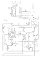
- FIG. 6 illustrates a group of embodiments, wherein the chilling unit 15 comprises a chilled coolant storage tank 311.
- the chilling unit 15 comprises a chilled coolant storage tank 311.
- the chilled coolant fluid 320 can then be retrieved from the chilled coolant storage tank and provided to the heat exchanger 4 even at times when the sun is not providing sufficient power to chill the coolant or to chill enough of the coolant.
- the amount of chilling duty provided can be varied by modulating the flow rate of the chilled coolant fluid 320 retrieved from the chilled coolant storage tank and provided to the heat exchanger 4.
- an auxiliary coolant fluid 420 may be provided in chilled form from the cold generator 14 (see Fig. 1 ).
- Cold duty may be passed from the auxiliary coolant fluid to the coolant present in the chilled coolant storage tank 311, e.g. via indirect heat exchange.
- an auxiliary return stream 424 may then be passed back to the cold generator 14.
- the auxiliary cooland fluid may be provided in the form of the chilling refrigerant from the chilling refrigerant cycle 3.
- the cold duty may be added to the coolant present in the chilled coolant storage tank 311 via direct heat exchange.
- chilled coolant fluid 320 may be directly passed from the cold generator to the heat exchanger 4 at times that actual cold generation capacity in the cold generator 14 is available. Any excess cold generation compared to the demand of chilling duty by the heat exchanger 4 may be used to produce excess chilled coolant fluid, which may be passed to the chilled coolant storage tank 311.
- chilled coolant fluid can be supplemented from the chilled coolant storage tank 311.
- a warm coolant storage tank which can be used to temporarily store a warm return stream at times that the cold generator does not have enough power to chill the return stream.
- energy may be stored in the form of heat storage (not shown).
- a heat storage unit may be provided wherein the thermal energy from the heated expansion stream 37 or heated heat transfer fluid stream 87 may be stored.
- the heat may be passed to a cold salt stream from a cold salt storage tank to generate a hot salt stream.
- the hot salt stream is passed to a hot salt storage tank where it can be stored until the thermal energy of the hot salt is required.
- a sixteen hour molten-salt storage system can allow CSP systems to be run on a 24 hour basis in Summertime when there is sufficient daytime sunlight.
- the captured solar thermal energy can be stored in a subsurface geologic reservoir, as described in U.S. Patent Application Publication No. 2006/0048770 .
- a supercritical fluid such as brine
- the supercritical fluid can be injected into a subsurface geologic reservoir through at least one injection well. Once charged with supercritical fluid, the subsurface geological formation forms a synthetic geothermal reservoir.
- the supercritical fluid can subsequently be extracted from the subsurface geologic reservoir through at least one extraction well bore, and the captured solar thermal energy released to provide the heated steam stream 37 and/or the heated heat transfer stream 87.
- the solar power for providing the power to be converted into chilling duty can be collected using a so-called concentrated solar power (CSP).
- CSP concentrated solar power
- a CSP system concentrates and collects direct solar energy to provide medium to high temperature heat.
- a CSP system may contain three main elements: one or more concentrators, one or more receivers and one or more expansion fluid circuits, suitably in the form of one or more steam circuits.
- the one or more concentrators reflect and concentrate solar energy, comprising light from the sun, onto the one or more receivers.
- the one or more receivers receive the reflected and concentrated sunlight and capture heat therefrom. The captured heat is then employed to heat the one or more expansion fluid streams in the expansion fluid circuit to provide the one or more heated expansion fluid streams.
- the one or more concentrators and one or more receivers form part of the CSP unit 9.
- Parabolic trough CSP systems use trough-shaped mirrors as the concentrators to reflect and concentrate sunlight onto one or more receivers in the form of tubes.
- An expansion fluid such as steam can be heated in the receiver tubes.
- solar steam can be generated this way at a pressure of 100 bar and a temperature of about 500°C.
- the CSP system can be used to heat a thermal transfer fluid to provide a heated thermal transfer fluid.
- the heated thermal transfer fluid is then heat exchanged with an expansion fluid to provide a thermal transfer fluid and a heated expansion fluid, the latter being used to power the first turbine.
- solar steam can be generated at a pressure of 100 bar and a temperature of about 375 °C.
- a linear Fresnel reflector array of concentrators can be used as an alternative to parabolic trough concentrators. This is a line focus system similar to parabolic trough systems in which solar radiation is concentrated on an elevated inverted linear receiver using an array of nearly flat reflectors.
- the use of linear concentrators provides a lower-cost alternative to parabolic trough concentrators and provides a number of advantages over parabolic systems such as lower structural support and concentrator costs, fixed fluid joints, a receiver separated from the concentrators and long focal lengths allowing the use of conventional glass.
- Central receiver (solar tower) CSP systems use a circular array of large individually tracking plain mirrors (heliostats) as the one or more concentrators to concentrate sunlight onto a central receiver mounted on top of a tower. Such systems can provide high conversion efficiencies. If pressurised gas or air is used as the thermal transfer or expansion fluid, temperatures of about 1000 °C or more may be achieved. In a similar manner to the parabolic trough CSP systems, the solar thermal energy can be captured directly in the expansion fluid or used to heat a thermal transfer fluid, which can be subsequently heat exchanged against the expansion fluid to generate the heated expansion fluid to power the first turbine.
- Parabolic dish CSP systems are smaller units which use dish shaped concentrators to reflect and concentrate sunlight onto a receiver situated at the focal point of the dish.
- the concentrated radiation is absorbed by the receiver and can heat a thermal transfer or expansion fluid to temperatures of about 750 °C.
- gas turbine systems and methods of operating a gas turbine system as described above may be employed in a method of cooling a gaseous hydrocarbon stream.
- Such a method may comprise:
- a common hydrocarbon stream to be liquefied is natural gas.
- processes that can be used to liquefy natural gas. Many of these processes involve two or more successive refrigerant cycles, often in a cascaded arrangement, for progressively lowering the temperature of the natural gas.
- Such refrigeration cycles typically comprise refrigerant compressors to recompress the refrigerants in the respective cycles after they have absorbed heat from the natural gas.
- These refrigerant compressors may be driven as external compressor by a gas turbine system as described herein.
- the medium to be compressed by the external compressor is formed by the gaseous hydrocarbon stream itself.
- the gaseous hydrocarbon stream By extracting heat from the gaseous hydrocarbon stream after compression, and thereafter expanding the gaseous hydrocarbon stream, the gaseous hydrocarbon stream will undergo cooling by the cooling duty generated. Part of the hydrocarbon stream may even be liquefied this way.
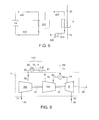
- the apparatus comprises a first refrigerant circuit 100 and a second refrigerant circuit 200.
- the medium to be compressed comprises the refrigerant in the first refrigerant circuit and/or the second refrigerant circuit.
- the first refrigerant circuit 100 comprises a system of lines containing a first refrigerant that can be cycled through the circuit.
- the second refrigerant circuit comprises a separate system of lines, containing a second refrigerant that can be cycled through the second refrigerant circuit 200.
- the first refrigerant circuit 100 comprises an external compressor in the form of first compressor 110.
- a first gas turbine 120 is coupled to the first compressor 110 via an external drive draft in the form of first drive shaft 115, to directly drive the first compressor 110.
- the first gas turbine 120 is associated with a first inlet air stream 125 as the oxygen-containing stream to the first gas turbine 120.
- the first compressor 110 is arranged to compress the first refrigerant in line 130.
- the refrigerant in line 130 may have passed though an optional suction drum 132 to ensure that no liquid constituents are fed into the first compressor 110.
- the second refrigerant circuit 200 comprises a second compressor 210 and a second gas turbine 220.
- the second gas turbine 220 is coupled to the second compressor 210 via a second drive shaft 215, to drive the second compressor 210.
- the second gas turbine 220 is associated with a second inlet air stream 225 as the oxygen-containing stream to the second gas turbine.
- the second compressor 210 is arranged to compress the second refrigerant in line 230.
- the refrigerant in line 230 may have passed though an optional suction drum 232 to ensure that no liquid constituents are fed into the second compressor 210.
- the respective first and second gas turbines 120, 220 are each associated with an inlet air cooling heat exchanger, in the form of a first inlet air cooling heat exchanger 127 and a second inlet air cooling heat exchanger 227, respectively. These inlet air cooling heat exchangers are arranged in the first respectively second inlet air stream 125, 225 to cool the first and second inlet air streams.
- filters may be provided in the first and second inlet air streams 125, 225 (not shown) to filter the air before it is compressed in the respective gas turbine 120, 220.
- Separators such as vertical vane type separators, and associated drain facilities may be provided downstream of the inlet air cooling heat exchangers 127, 227 to remove moisture that may develop during the cooling of the inlet air stream(s). Drain facilities may also be provided in the air cooling heat exchangers 127, 227 to drain of moisture from these heat exchangers.
- the suction inlet of the second compressor 210 is connected to a second refrigerant outlet 262 of a second heat exchanger 260 via the line 230 and the optional suction drum 232.
- the second heat exchanger 260 is one or one or more second heat exchangers, arranged to receive and liquefy a cooled hydrocarbon stream in line 80, so as to provide a liquefied hydrocarbon stream 20.
- the outlet of the second compressor 210 is connected to line 119 that is provided with one or more ambient coolers 217.
- the outlet of the first compressor 110 is connected to one or more first heat exchangers 140a, 140b via a refrigerant line 119. Upstream of the one or more first heat exchangers 140a, 140b, one or more ambient coolers 117 are provided in the refrigerant line 119. Pressure reduction devices 142a, 142b are provided upstream of the one or more first heat exchangers 140a, 140b to regulate the pressure in these heat exchangers.
- the one or more heat exchangers 140a, 140b have refrigerant outlets that are connected to the first refrigerant compressor 110 via lines 134a and 134b. In the embodiment shown in Figure 1 , the lines 134a and 134b connect to the first refrigerant compressor 110 via the optional suction drum 132.
- two of the one or more heat exchangers 140a, 140b are arranged in a parallel configuration, and each have a single warm tube or warm tube bundle 141a, 141b.
- One of the one or more first heat exchangers is arranged to receive and cool the gaseous hydrocarbon stream 10. This one will be referred to as first hydrocarbon feed heat exchanger 140a.
- first hydrocarbon feed heat exchanger 140a there are one or more other first heat exchangers arranged in the hydrocarbon feed line 10 upstream of the first hydrocarbon feed heat exchanger 140a, to be operated at higher pressures than the first hydrocarbon feed heat exchanger 140a.
- Line 40 downstream of the first hydrocarbon feed heat exchanger may be connected directly to line 80 that connects to the second heat exchanger 260 in order to provide the cooled hydrocarbon stream to line 80.
- the line 40 is connected to an optional gas/liquid separator 50, here provided in the form of a scrub column that is provided to receive the hydrocarbon stream 40 at approximately the hydrocarbon feed gas pressure, after it has passed through the first hydrocarbon feed heat exchanger 140a.
- the optional gas/liquid separator 50 has an overhead outlet for discharging a vaporous overhead stream 60 and a bottom outlet for discharging a liquid bottom stream 70.
- Line 60 for the vaporous overhead stream 60 may be connected to line 80 to provide the cooled hydrocarbon stream in line 80.
- a splitter 63 may be provided in line 60 or line 80, to draw off a fuel gas stream 62 from the vaporous overhead stream 60.
- the liquid bottom stream 70 which may typically comprise C 2 to C 4 constituents as well as C 5 +, may be connected to an optional fractionation train 75 to fractionate at least a part of the bottom stream 70 into fractionation product streams 76.
- first second refrigerant heat exchanger 140b Another one of the one or more first heat exchangers, which will hereinafter be referenced as first second refrigerant heat exchanger 140b, is arranged to receive the second refrigerant from line 219.
- line 219 is connected to the warm tube (or warm tube bundle) 141b.
- first heat exchangers arranged in the second refrigerant line 219 upstream of the first second refrigerant heat exchanger 140b, to be operated at higher pressures than the first second refrigerant heat exchanger 140b.
- an optional refrigerant gas/liquid separator 250 is provided downstream of the first second refrigerant heat exchanger to receive the cooled second refrigerant stream 240 after it has passed through the first second refrigerant heat exchanger 140b and separate it into cooled at least by heat exchanging with said first refrigerant from the first refrigerant circuit.
- the cooled hydrocarbon stream 80 and the second refrigerant stream 240 are connected to the one or more second heat exchangers 260, to further cool and liquefy the cooled hydrocarbon stream 80 to obtain at least an intermediate liquefied hydrocarbon stream 90 and an at least partially or fully evaporated refrigerant stream 265 at the outlet 262.
- Line 90 may be connected to depressurizing equipment comprising optional phase separation equipment to separate flash vapour from the remaining liquid.
- the depressurizing equipment is here embodied as one or more expansion devices 97 to produce a depressurized stream 98 followed by a phase separator 99.
- the expansion devices may be embodied in the form of an isentropic expander such as work-expander 95 which may be provided in the form of a turbine, and/or an isenthalpic expander such as a Joule-Thomson valve 96.
- the isenthalpic expander 96 is suitably be provided downstream of the isentropic expander 95.
- the apparatus further comprises a coolant circuit 300, wherein a coolant fluid can be circulated for chilling the first and second inlet air streams 125, 225.
- a storage tank 310 wherein the coolant fluid can be stored.
- the coolant fluid is preferably a liquid and/or inflammable for safety reasons.
- the coolant circuit 300 further comprises a chiller heat exchanger 325 to provide a chilled coolant 320.
- the chiller heat exchanger 325 is arranged to receive cooling duty 18 and capable of withdrawing heat from the coolant fluid and thereby to provide the chilled coolant in line 320. For instance, it may be arranged to receive the chilling refrigerant from the chilling refrigerant cycle 3 of any one of figures 2 to 4 , or it may for instance be integrated into the evaporator of the thermally driven chiller 33 of Figure 5 .
- a pump 305 is provided.
- the pump may be provided anywhere in the circuit.
- the pump 305 has its low pressure inlet connected to the storage tank 310 via line 315 and its high-pressure outlet connected to the chiller 325.
- a combiner 338 may be provided downstream of the first and second inlet air cooling heat exchangers 127, 227 in order to form a single return stream 324 of the coolant fluid.
- the divider as shown in Figure 7 comprises a junction 337, such as a T-piece, a first flow control valve 338 in line 340, and a second flow control valve 339 in line 350.
- the combiner 338 may be provided in the form of a junction, such as a T-piece.
- the cooling duty available in the chilled coolant may be divided essentially in any ratio between the first and second parts, ranging from 0:1 to 1:0.
- the first inlet air cooling heat exchanger 127 is arranged in line 340 to cool the first inlet air stream 125 with the first part of the chilled coolant.
- the second inlet air cooling heat exchanger 227 is arranged in the second inlet air stream to cool the second inlet air stream with the second part of the chilled coolant.
- the system works as follows.
- the gas turbines 120 and 220 each take in an inlet air stream and a fuel stream and provide mechanical power on the respective drive shafts 115, 215.
- the drive shafts are mechanically coupled to respective first and second compressors 110, 210 and thus the compressors are driven.
- the first refrigerant in the first refrigerant circuit 100 is compressed in compressor 110, cooled against ambient in one or more coolers 117 and distributed over one or more first heat exchangers 140a, 140b.
- cooling of the first refrigerant in the cooler(s) 117 causes it to partially, preferably fully, condense.
- the pressure is let down in the reduction devices 142a, 142b.
- the first refrigerant is then allowed to evaporate in the first heat exchangers 140a, 140b by drawing heat from the warm tubes or tube bundles 141a, 141b.
- the evaporated first refrigerant is led back to the first compressor 110.
- the second refrigerant in the second refrigerant circuit 200 is compressed in compressor 210, cooled against ambient in one or more coolers 217 and then further cooled in one or more of the first heat exchangers. As depicted in Figure 7 , the further cooling of the second refrigerant is achieved by passing it through warm tube 141b in first second refrigerant heat exchanger 140b where it is cooled at least by heat exchanging with said first refrigerant, to produce a partially condensed second refrigerant stream 240.
- the partially condensed second refrigerant stream 240 is separated into vapour and liquid second refrigerant phases 252 respectively 254. These stream are then condensed and sub-cooled, respectively subcooled, in the one or more second heat exchangers 260 in a manner well known in the art.
- the partially condensed hydrocarbon stream 40 is separated into vaporous overhead stream 60 and liquid bottom stream 70.
- at least a part of the bottom stream 70 is warmed in a bottom stream heat exchanger, in which case at least part of the warmed bottom stream may be fed back to the optional gas/liquid separator 50 as a reboiled stream.
- the bottom stream 70, or at least the remaining part of it, is typically led to the fractionation train 75 where it is fractionated into one or more fractionation product streams.
- the vaporous overhead stream 60 is fed into line 80 as a cooled hydrocarbon stream 80.
- the cooled hydrocarbon stream 80 is then fed to one or more of the second heat exchangers 260 in a manner known in the art where it is liquefied using the second refrigerant.
- an intermediate liquefied hydrocarbon stream 90 is produced.
- This intermediate liquefied hydrocarbon stream 90 may be depressurized in the one or more expansion devices 97 and the depressurized stream 98 led to phase separator 99, where any vaporous constituents, mainly flash vapour, are separated from the liquid hydrocarbons in stream 98.
- the liquid hydrocarbons are removed from the phase separator 99 as liquefied hydrocarbon product stream 20, the vaporous constituents are drawn from the phase separator 99 as end flash stream 92.
- the coolant fluid in the storage tank 310 is pumped or otherwise led to chiller 325, wherein it is actively chilled to provide chilled coolant 320 by heat exchanging against cold fluid 327.
- the cooling duty available in the chilled coolant 320 is divided over at least first and second parts.
- the cooling duty may for instance be divided by physically splitting the chilled coolant 320 over two or more part streams, such as two part streams 340, 350 in the embodiment of Figure 7 .
- the first part stream 340 is used to cool the first inlet air stream 125 and the second part stream 350 is used to cool the second inlet air stream 225.
- the coolant After having cooled the first and/or second inlet air streams 125, 225, the coolant may be recombined and led to the storage tank 310 for re-use.
- the inlet air streams 125, 225 are preferably not cooled to lower than about 5 °C to ensure that formation of ice is avoided.
- the cooling duty for actively chilling of the coolant fluid in the one or more chillers 325 may be obtained as described above with reference to Figures 1 to 5 .
- the second refrigerant may be fully condensed after its cooling against the first refrigerant.
- the optional refrigerant gas/liquid separator 250 need not be provided.
- the second refrigerant is not fully condensed but wherein nevertheless no gas/liquid phase separation is needed, for instance because full condensation is achieved in a subsequent heat exchanging against a further refrigerant or by auto-cooling.
- first compressor 110 may have a multiple of inlets at different pressure levels in a manner known in the art.
- the first compressor 110 and/or the second compressor 210 may each be embodied in the form of two or more successive or parallel arranged frames, in a manner known in the art.
- an overhead heat exchanger may be provided in line 60 in a way known in the art.
- Such an overhead heat exchanger may form part of the one or more first heat exchangers, and it may for instance be connected to line 119 to obtain a fraction of the first refrigerant.
- an optional overhead gas/liquid separator is provided downstream of the overhead heat exchanger in order to remove any condensed fraction from stream downstream of the overhead heat exchanger.
- the vapour outlet of the overhead gas/liquid separator may then be connected to line 80 to provide the cooled hydrocarbon stream.
- the bottom liquid outlet of the overhead gas/liquid separator may be connected to the gas/liquid separator 50 to feed back at least a portion of the condensed fraction as a reflux stream.
- the fuel gas stream 62 may be drawn from the vapour stream.
- the optional gas/liquid separator 50 is located upstream of the first hydrocarbon feed heat exchanger 140a.
- the overhead outlet of the gas/liquid separator could in such an alternative embodiment be connected to line 10 in Figure 7 , and line 40 could the be connected directly to line 80 to provide the cooled hydrocarbon stream to the second heat exchanger 260.
- Such embodiments may have an expander upstream of the optional gas/liquid separator 50, and typically one or more recompressors and/or booster compressors upstream of the first hydrocarbon feed heat exchanger 140a, and/or other heat exchangers to pre-cool the feed to the optional gas/liquid separator 50.
- Such embodiments are known in the art and need not be further detailed here.
- the first refrigerant is a single component refrigerant consisting essentially of propane, while the second refrigerant is a mixed refrigerant.
- a mixed refrigerant or a mixed refrigerant stream as referred to herein comprises at least 5 mol% of two different components.
- the mixed refrigerant may contain two or more components selected from the group consisting of: nitrogen, methane, ethane, ethylene, propane, propylene, butanes.
- a common composition for a mixed refrigerant can be: Nitrogen 0-10 mol% Methane (C1) 30-70 mol% Ethane (C2) 30-70 mol% Propane (C3) 0-30 mol% Butanes (C4) 0-15 mol%
- the total composition comprises 100 mol%.
- the methods and apparatus disclosed herein may further involve the use of one or more other refrigerants, in separate or overlapping refrigerant circuits or other cooling circuits.
- the first refrigerant may be a mixed refrigerant (such as described for instance in US Pat. 6,370,910 ) and/or the second refrigerant may be a single component refrigerant (such as consisting essentially of ethane, ethylene, methane or nitrogen).
- the type of heat exchanger may be selected differently from the kettle types heat exchangers that have been depicted in Figure 7 , for instance tube-in-shell type heat exchangers such as coil wound heat exchangers.
- the gaseous hydrocarbon stream 10 to be cooled and liquefied may be derived from any suitable gas stream to be cooled and liquefied, such as a natural gas stream obtained from natural gas or petroleum reservoirs or coal beds.
- the gaseous hydrocarbon stream 10 may also be obtained from another source, including as an example a synthetic source such as a Fischer-Tropsch process.
- the gaseous hydrocarbon stream 10 is a natural gas stream, it is usually comprised substantially of methane.
- the gaseous hydrocarbon stream 10 comprises at least 50 mol% methane, more preferably at least 80 mol% methane.
- natural gas may contain varying amounts of hydrocarbons heavier than methane such as in particular ethane, propane and the butanes, and possibly lesser amounts of pentanes and aromatic hydrocarbons.
- hydrocarbons heavier than methane such as in particular ethane, propane and the butanes, and possibly lesser amounts of pentanes and aromatic hydrocarbons.
- the composition varies depending upon the type and location of the gas.
- hydrocarbons heavier than methane are removed as far as needed to produce a liquefied hydrocarbon product stream in accordance with a desired specification.
- Hydrocarbons heavier than butanes (C 4 ) are removed as far as efficiently possible from the natural gas prior to any significant cooling for several reasons, such as having different freezing or liquefaction temperatures that may cause them to block parts of a methane liquefaction plant.
- the natural gas may also contain non-hydrocarbons such as H 2 O N 2 , CO 2 Hg, H 2 S and other sulphur compounds, and the like.
- the gaseous hydrocarbon stream 10 comprising the natural gas may be pre-treated before cooling and at least partial liquefaction. This pre-treatment may comprise reduction and/or removal of undesired components such as CO 2 and H 2 S or other steps such as early cooling, pre-pressurizing or the like. As these steps are well known to the person skilled in the art, their mechanisms are not further discussed here.
- the system and method for cooling the hydrocarbon stream described hereinabove is not limited to two refrigeration circuits: it can also be applied for dividing cooling duty of the chilled coolant over three or more parts for cooling third or more inlet air streams of other refrigerant circuits.
- Some gas turbines for example type LMS100 TM by General Electric as published in the GE Energy publication GER-422A (06/04) titled “New High Efficiency Simple Cycle Gas Turbine - GE's LMS100TM", have an intercooler between low and high pressure compression stages used to compress an air stream which is passed to the combustion chamber.
- the presently proposed methods and apparatus are also envisaged to form part of such intercooling stage and to cover solar-powered chilling of such intercooling of the oxydizing stream.
- the intercooling stage thus comprises a solar powered chilling step to bring a low pressure compressed oxygen-containing stream in the intercooling stage to an intercooling temperature that is lower than ambient temperature.
- the method may comprise selecting a gas turbine 5 having a low pressure compression stage 150 usually comprising a low pressure compressor 150; a high pressure compression stage 160 usually comprising a high pressure compressor 160; a combustion chamber 7, and an expansion stage 8 usually comprising an expansion turbine 8.
- the oxygen-containing stream 45 is:
- This low pressure compressed oxygen-containing stream 55 is then chilled as described hereinabove, while it is passed through the intercooling stage 120 to the high pressure compression stage 160. After said chilling, the temperature (hereinafter referred to as the intercooling temperature) is lower than the ambient temperature.
- the chilled low pressure compressed oxydizing stream 56 coming from the intercooling stage 120 is then compressed in the high pressure compression stage 160 to provide a high pressure oxydizing stream 65, which is then passed to the combustion chamber 7.
- a gas turbine system employing solar powered intercooling chilling as described above is shown in Figure 8 .
- the system comprises gas turbine 5 with an oxydizing stream compressor comprising low pressure compressor 150 and a high pressure compressor 160.
- gas turbines having two compression stages in the form of a low pressure compressor and a high pressure compressor are found amongst the group of a aeroderivative gas turbines.
- a first air inlet 51 into the gas turbine 5 is arranged to take in a oxygen-containing stream in the form of air inlet stream 45 from an air source at an ambient temperature.
- the low pressure compression stage 150 connects the first air inlet 51 with a low pressure compressed air stream outlet 52 from the gas turbine 5.
- the intercooling stage 120 is arranged to receive the low pressure compressed air stream 55 passing through the low pressure compressed air stream outlet 52.
- the intercooling stage 120 is provided with an ambient cooler 30 and heat exchanger 4. The latter is arranged to chill the ambient-cooled oxygen-containing stream 35 using chilling duty generated from solar power in accordance with one or more of the methods and systems described hereinabove.
- the temperature of the chilled oxydizing stream in the form of intercooled air stream 56 is at least 5 °C below the ambient temperature of the air source.
- the gas turbine 5 further has a second air inlet 61 into the gas turbine 5 for taking in the intercooled air stream 56 from the intercooling stage 120.
- the combustion chamber is connected to the second air inlet 61 via the high pressure compressor 160 on one end and to the expansion turbine 8 on the other end.
- Fuel stream inlet 71 is provided into the gas turbine 5 for allowing the fuel stream 69 into the combustion chamber 7.
- the gas turbine system comprises a first mechanical drive shaft 24 connecting the expansion turbine 8 with the high pressure compressor 160, and a second mechanical drive shaft 22 connecting the low pressure compressor 150 with the high pressure compressor 160.
- low and high pressure compression stages are intended to encompass compressors housed in a single casing, or those in which multiple compressors are arranged in series on a common mechanical drive shaft or shafts, to sequentially compress the air inlet stream 45.
- the external drive shaft 26 of the gas turbine system as illustrated in Figure 8 may drive an external compressor, such as compressors 110, 210 as illustrated in Figure 7 , or perform other duty.
Landscapes
- Engineering & Computer Science (AREA)
- General Engineering & Computer Science (AREA)
- Mechanical Engineering (AREA)
- Physics & Mathematics (AREA)
- Thermal Sciences (AREA)
- Chemical & Material Sciences (AREA)
- Combustion & Propulsion (AREA)
- Sustainable Energy (AREA)
- Sustainable Development (AREA)
- Life Sciences & Earth Sciences (AREA)
- High Energy & Nuclear Physics (AREA)
- Chemical Kinetics & Catalysis (AREA)
- General Chemical & Material Sciences (AREA)
- Oil, Petroleum & Natural Gas (AREA)
- Engine Equipment That Uses Special Cycles (AREA)
Priority Applications (2)
| Application Number | Priority Date | Filing Date | Title |
|---|---|---|---|
| EP09177647A EP2330280A1 (fr) | 2009-12-01 | 2009-12-01 | Procédé de fonctionnement d'une turbine à gaz, système de turbine à gaz, procédé et système pour refroidir un flux d'hydrocarbures |
| AU2010246499A AU2010246499B8 (en) | 2009-12-01 | 2010-11-29 | Method and system for cooling a hydrocarbon stream |
Applications Claiming Priority (1)
| Application Number | Priority Date | Filing Date | Title |
|---|---|---|---|
| EP09177647A EP2330280A1 (fr) | 2009-12-01 | 2009-12-01 | Procédé de fonctionnement d'une turbine à gaz, système de turbine à gaz, procédé et système pour refroidir un flux d'hydrocarbures |
Publications (1)
| Publication Number | Publication Date |
|---|---|
| EP2330280A1 true EP2330280A1 (fr) | 2011-06-08 |
Family
ID=42133796
Family Applications (1)
| Application Number | Title | Priority Date | Filing Date |
|---|---|---|---|
| EP09177647A Withdrawn EP2330280A1 (fr) | 2009-12-01 | 2009-12-01 | Procédé de fonctionnement d'une turbine à gaz, système de turbine à gaz, procédé et système pour refroidir un flux d'hydrocarbures |
Country Status (1)
| Country | Link |
|---|---|
| EP (1) | EP2330280A1 (fr) |
Cited By (8)
| Publication number | Priority date | Publication date | Assignee | Title |
|---|---|---|---|---|
| WO2012122350A1 (fr) * | 2011-03-08 | 2012-09-13 | Poerio Wayne | Climatisation à turbopompe solaire et chauffage hybride et procédé de fonctionnement |
| ITMI20121625A1 (it) * | 2012-09-28 | 2014-03-29 | Eni Spa | Circuito refrigerante per la liquefazione del gas naturale |
| WO2014128056A1 (fr) * | 2013-02-25 | 2014-08-28 | Dürr Systems GmbH | Installation de combustion, installation de traitement de pièces et procédé de fonctionnement d'une installation de combustion |
| JPWO2013124899A1 (ja) * | 2012-02-24 | 2015-05-21 | 三菱日立パワーシステムズ株式会社 | 太陽熱アシストガスタービンシステム |
| US9772127B2 (en) | 2011-03-08 | 2017-09-26 | JOI Scientific, Inc. | Solar turbo pump—hybrid heating-air conditioning and method of operation |
| CN110173356A (zh) * | 2019-06-10 | 2019-08-27 | 中节能城市节能研究院有限公司 | 一种基于制冷剂冷却的燃气轮机入口燃气压缩机组 |
| IT201900008367A1 (it) * | 2019-06-07 | 2020-12-07 | Nuovo Pignone Tecnologie Srl | Un sistema di liquefazione di gas naturale |
| CN114111105A (zh) * | 2021-11-25 | 2022-03-01 | 浙江态能动力技术有限公司 | 一种基于二元气体超高温热泵的综合能源系统 |
Citations (5)
| Publication number | Priority date | Publication date | Assignee | Title |
|---|---|---|---|---|
| DE2409765A1 (de) * | 1973-10-11 | 1975-04-17 | Gilberto Forti | Verfahren zur nutzung der sonnenenergie |
| US4464908A (en) * | 1982-08-12 | 1984-08-14 | The United States Of America As Represented By The United States Department Of Energy | Solar-powered turbocompressor heat pump system |
| US6370910B1 (en) | 1998-05-21 | 2002-04-16 | Shell Oil Company | Liquefying a stream enriched in methane |
| US20030074901A1 (en) * | 1997-06-18 | 2003-04-24 | Bellac Alphonse H. | Solar power enhanced combustion turbine power plants and methods |
| US20060048770A1 (en) | 2004-09-08 | 2006-03-09 | Sovani Meksvanh | Solar augmented geothermal energy |
-
2009
- 2009-12-01 EP EP09177647A patent/EP2330280A1/fr not_active Withdrawn
Patent Citations (5)
| Publication number | Priority date | Publication date | Assignee | Title |
|---|---|---|---|---|
| DE2409765A1 (de) * | 1973-10-11 | 1975-04-17 | Gilberto Forti | Verfahren zur nutzung der sonnenenergie |
| US4464908A (en) * | 1982-08-12 | 1984-08-14 | The United States Of America As Represented By The United States Department Of Energy | Solar-powered turbocompressor heat pump system |
| US20030074901A1 (en) * | 1997-06-18 | 2003-04-24 | Bellac Alphonse H. | Solar power enhanced combustion turbine power plants and methods |
| US6370910B1 (en) | 1998-05-21 | 2002-04-16 | Shell Oil Company | Liquefying a stream enriched in methane |
| US20060048770A1 (en) | 2004-09-08 | 2006-03-09 | Sovani Meksvanh | Solar augmented geothermal energy |
Cited By (15)
| Publication number | Priority date | Publication date | Assignee | Title |
|---|---|---|---|---|
| WO2012122350A1 (fr) * | 2011-03-08 | 2012-09-13 | Poerio Wayne | Climatisation à turbopompe solaire et chauffage hybride et procédé de fonctionnement |
| US9772127B2 (en) | 2011-03-08 | 2017-09-26 | JOI Scientific, Inc. | Solar turbo pump—hybrid heating-air conditioning and method of operation |
| JPWO2013124899A1 (ja) * | 2012-02-24 | 2015-05-21 | 三菱日立パワーシステムズ株式会社 | 太陽熱アシストガスタービンシステム |
| JP2016500800A (ja) * | 2012-09-28 | 2016-01-14 | イーエヌアイ ソシエタ ペル アチオニEni S.P.A. | 天然ガスの液化のための冷却回路 |
| ITMI20121625A1 (it) * | 2012-09-28 | 2014-03-29 | Eni Spa | Circuito refrigerante per la liquefazione del gas naturale |
| WO2014048845A1 (fr) * | 2012-09-28 | 2014-04-03 | Eni S.P.A | Circuit de refroidissement pour la liquéfaction de gaz naturel |
| WO2014128056A1 (fr) * | 2013-02-25 | 2014-08-28 | Dürr Systems GmbH | Installation de combustion, installation de traitement de pièces et procédé de fonctionnement d'une installation de combustion |
| CN105074336B (zh) * | 2013-02-25 | 2017-09-19 | 杜尔系统股份公司 | 燃烧机组、工件处理机组和用于运行燃烧机组的方法 |
| CN105074336A (zh) * | 2013-02-25 | 2015-11-18 | 杜尔系统有限公司 | 燃烧机组、工件处理机组和用于运行燃烧机组的方法 |
| IT201900008367A1 (it) * | 2019-06-07 | 2020-12-07 | Nuovo Pignone Tecnologie Srl | Un sistema di liquefazione di gas naturale |
| WO2020244809A1 (fr) * | 2019-06-07 | 2020-12-10 | Nuovo Pignone Tecnologie - S.R.L. | Système de liquéfaction de gaz naturel |
| WO2020244808A1 (fr) * | 2019-06-07 | 2020-12-10 | Nuovo Pignone Tecnologie - S.R.L. | Système de liquéfaction de gaz naturel utilisant de l'énergie renouvelable pour produire de l'hydrogène |
| CN110173356A (zh) * | 2019-06-10 | 2019-08-27 | 中节能城市节能研究院有限公司 | 一种基于制冷剂冷却的燃气轮机入口燃气压缩机组 |
| CN114111105A (zh) * | 2021-11-25 | 2022-03-01 | 浙江态能动力技术有限公司 | 一种基于二元气体超高温热泵的综合能源系统 |
| CN114111105B (zh) * | 2021-11-25 | 2023-01-31 | 浙江态能动力技术有限公司 | 一种基于二元气体超高温热泵的综合能源系统 |
Similar Documents
| Publication | Publication Date | Title |
|---|---|---|
| US11578623B2 (en) | Cryogenic combined cycle power plant | |
| KR101334068B1 (ko) | 액체 공기 생산, 동력 저장 및 동력 방출 시스템 및 장치 | |
| EP2330280A1 (fr) | Procédé de fonctionnement d'une turbine à gaz, système de turbine à gaz, procédé et système pour refroidir un flux d'hydrocarbures | |
| CA2815003C (fr) | Systeme et procede de production d'air liquide, stockage de l'energie et liberation de l'energie | |
| US20120255302A1 (en) | Heating, cooling and power generation system | |
| US20120255312A1 (en) | Method and System to Produce Electric Power | |
| WO2009153143A1 (fr) | Procédé permettant de faire fonctionner un compresseur à l'énergie solaire concentrée et appareil à cet effet | |
| US20120038172A1 (en) | Renewable power storage utilizing liquid gas | |
| US12258883B2 (en) | Charge, storage, and discharge energy system using liquid air and sCO2 | |
| JPH10238367A (ja) | エネルギ貯蔵型ガスタービン発電システム | |
| JPWO2008136121A1 (ja) | 天然ガス液化設備 | |
| AU2010246499B8 (en) | Method and system for cooling a hydrocarbon stream | |
| AU2021392776B2 (en) | A system for producing liquefied natural gas and method | |
| US10557414B1 (en) | Combined cycle energy recovery method and system | |
| RU2812381C1 (ru) | Способ работы парогазовой установки | |
| EP4495520A1 (fr) | Unité de prérefroidissement pour une installation de production de gaz naturel liquéfié à rendement amélioré | |
| CN109296418B (zh) | 用于从压力能到电能的能量转换的方法和设备 | |
| EA040663B1 (ru) | Система для обработки и охлаждения потока углеводородов | |
| HK1217358A1 (zh) | 用於节能的方法 |
Legal Events
| Date | Code | Title | Description |
|---|---|---|---|
| PUAI | Public reference made under article 153(3) epc to a published international application that has entered the european phase |
Free format text: ORIGINAL CODE: 0009012 |
|
| AK | Designated contracting states |
Kind code of ref document: A1 Designated state(s): AT BE BG CH CY CZ DE DK EE ES FI FR GB GR HR HU IE IS IT LI LT LU LV MC MK MT NL NO PL PT RO SE SI SK SM TR |
|
| STAA | Information on the status of an ep patent application or granted ep patent |
Free format text: STATUS: THE APPLICATION HAS BEEN WITHDRAWN |
|
| 18W | Application withdrawn |
Effective date: 20111206 |