EP2330285A1 - Dispositif de commande pour moteur - Google Patents
Dispositif de commande pour moteur Download PDFInfo
- Publication number
- EP2330285A1 EP2330285A1 EP09814202A EP09814202A EP2330285A1 EP 2330285 A1 EP2330285 A1 EP 2330285A1 EP 09814202 A EP09814202 A EP 09814202A EP 09814202 A EP09814202 A EP 09814202A EP 2330285 A1 EP2330285 A1 EP 2330285A1
- Authority
- EP
- European Patent Office
- Prior art keywords
- exhaust
- engine
- flow rate
- heat quantity
- exhaust heat
- Prior art date
- Legal status (The legal status is an assumption and is not a legal conclusion. Google has not performed a legal analysis and makes no representation as to the accuracy of the status listed.)
- Withdrawn
Links
Images

Classifications
-
- F—MECHANICAL ENGINEERING; LIGHTING; HEATING; WEAPONS; BLASTING
- F02—COMBUSTION ENGINES; HOT-GAS OR COMBUSTION-PRODUCT ENGINE PLANTS
- F02D—CONTROLLING COMBUSTION ENGINES
- F02D41/00—Electrical control of supply of combustible mixture or its constituents
- F02D41/02—Circuit arrangements for generating control signals
- F02D41/021—Introducing corrections for particular conditions exterior to the engine
- F02D41/0235—Introducing corrections for particular conditions exterior to the engine in relation with the state of the exhaust gas treating apparatus
- F02D41/024—Introducing corrections for particular conditions exterior to the engine in relation with the state of the exhaust gas treating apparatus to increase temperature of the exhaust gas treating apparatus
- F02D41/0245—Introducing corrections for particular conditions exterior to the engine in relation with the state of the exhaust gas treating apparatus to increase temperature of the exhaust gas treating apparatus by increasing temperature of the exhaust gas leaving the engine
-
- F—MECHANICAL ENGINEERING; LIGHTING; HEATING; WEAPONS; BLASTING
- F02—COMBUSTION ENGINES; HOT-GAS OR COMBUSTION-PRODUCT ENGINE PLANTS
- F02D—CONTROLLING COMBUSTION ENGINES
- F02D41/00—Electrical control of supply of combustible mixture or its constituents
- F02D41/02—Circuit arrangements for generating control signals
- F02D41/14—Introducing closed-loop corrections
- F02D41/1438—Introducing closed-loop corrections using means for determining characteristics of the combustion gases; Sensors therefor
- F02D41/1444—Introducing closed-loop corrections using means for determining characteristics of the combustion gases; Sensors therefor characterised by the characteristics of the combustion gases
- F02D41/1445—Introducing closed-loop corrections using means for determining characteristics of the combustion gases; Sensors therefor characterised by the characteristics of the combustion gases the characteristics being related to the exhaust flow
-
- F—MECHANICAL ENGINEERING; LIGHTING; HEATING; WEAPONS; BLASTING
- F02—COMBUSTION ENGINES; HOT-GAS OR COMBUSTION-PRODUCT ENGINE PLANTS
- F02D—CONTROLLING COMBUSTION ENGINES
- F02D41/00—Electrical control of supply of combustible mixture or its constituents
- F02D41/02—Circuit arrangements for generating control signals
- F02D41/14—Introducing closed-loop corrections
- F02D41/1438—Introducing closed-loop corrections using means for determining characteristics of the combustion gases; Sensors therefor
- F02D41/1444—Introducing closed-loop corrections using means for determining characteristics of the combustion gases; Sensors therefor characterised by the characteristics of the combustion gases
- F02D41/1446—Introducing closed-loop corrections using means for determining characteristics of the combustion gases; Sensors therefor characterised by the characteristics of the combustion gases the characteristics being exhaust temperatures
- F02D41/1447—Introducing closed-loop corrections using means for determining characteristics of the combustion gases; Sensors therefor characterised by the characteristics of the combustion gases the characteristics being exhaust temperatures with determination means using an estimation
-
- F—MECHANICAL ENGINEERING; LIGHTING; HEATING; WEAPONS; BLASTING
- F01—MACHINES OR ENGINES IN GENERAL; ENGINE PLANTS IN GENERAL; STEAM ENGINES
- F01N—GAS-FLOW SILENCERS OR EXHAUST APPARATUS FOR MACHINES OR ENGINES IN GENERAL; GAS-FLOW SILENCERS OR EXHAUST APPARATUS FOR INTERNAL-COMBUSTION ENGINES
- F01N2560/00—Exhaust systems with means for detecting or measuring exhaust gas components or characteristics
- F01N2560/07—Exhaust systems with means for detecting or measuring exhaust gas components or characteristics the means being an exhaust gas flow rate or velocity meter or sensor, intake flow meters only when exclusively used to determine exhaust gas parameters
-
- F—MECHANICAL ENGINEERING; LIGHTING; HEATING; WEAPONS; BLASTING
- F01—MACHINES OR ENGINES IN GENERAL; ENGINE PLANTS IN GENERAL; STEAM ENGINES
- F01N—GAS-FLOW SILENCERS OR EXHAUST APPARATUS FOR MACHINES OR ENGINES IN GENERAL; GAS-FLOW SILENCERS OR EXHAUST APPARATUS FOR INTERNAL-COMBUSTION ENGINES
- F01N3/00—Exhaust or silencing apparatus having means for purifying, rendering innocuous, or otherwise treating exhaust
- F01N3/02—Exhaust or silencing apparatus having means for purifying, rendering innocuous, or otherwise treating exhaust for cooling, or for removing solid constituents of, exhaust
- F01N3/021—Exhaust or silencing apparatus having means for purifying, rendering innocuous, or otherwise treating exhaust for cooling, or for removing solid constituents of, exhaust by means of filters
-
- F—MECHANICAL ENGINEERING; LIGHTING; HEATING; WEAPONS; BLASTING
- F01—MACHINES OR ENGINES IN GENERAL; ENGINE PLANTS IN GENERAL; STEAM ENGINES
- F01N—GAS-FLOW SILENCERS OR EXHAUST APPARATUS FOR MACHINES OR ENGINES IN GENERAL; GAS-FLOW SILENCERS OR EXHAUST APPARATUS FOR INTERNAL-COMBUSTION ENGINES
- F01N3/00—Exhaust or silencing apparatus having means for purifying, rendering innocuous, or otherwise treating exhaust
- F01N3/08—Exhaust or silencing apparatus having means for purifying, rendering innocuous, or otherwise treating exhaust for rendering innocuous
- F01N3/10—Exhaust or silencing apparatus having means for purifying, rendering innocuous, or otherwise treating exhaust for rendering innocuous by thermal or catalytic conversion of noxious components of exhaust
-
- F—MECHANICAL ENGINEERING; LIGHTING; HEATING; WEAPONS; BLASTING
- F02—COMBUSTION ENGINES; HOT-GAS OR COMBUSTION-PRODUCT ENGINE PLANTS
- F02D—CONTROLLING COMBUSTION ENGINES
- F02D2400/00—Control systems adapted for specific engine types; Special features of engine control systems not otherwise provided for; Power supply, connectors or cabling for engine control systems
- F02D2400/08—Redundant elements, e.g. two sensors for measuring the same parameter
-
- F—MECHANICAL ENGINEERING; LIGHTING; HEATING; WEAPONS; BLASTING
- F02—COMBUSTION ENGINES; HOT-GAS OR COMBUSTION-PRODUCT ENGINE PLANTS
- F02D—CONTROLLING COMBUSTION ENGINES
- F02D41/00—Electrical control of supply of combustible mixture or its constituents
- F02D41/02—Circuit arrangements for generating control signals
- F02D41/021—Introducing corrections for particular conditions exterior to the engine
- F02D41/0235—Introducing corrections for particular conditions exterior to the engine in relation with the state of the exhaust gas treating apparatus
- F02D41/027—Introducing corrections for particular conditions exterior to the engine in relation with the state of the exhaust gas treating apparatus to purge or regenerate the exhaust gas treating apparatus
-
- F—MECHANICAL ENGINEERING; LIGHTING; HEATING; WEAPONS; BLASTING
- F02—COMBUSTION ENGINES; HOT-GAS OR COMBUSTION-PRODUCT ENGINE PLANTS
- F02D—CONTROLLING COMBUSTION ENGINES
- F02D41/00—Electrical control of supply of combustible mixture or its constituents
- F02D41/02—Circuit arrangements for generating control signals
- F02D41/14—Introducing closed-loop corrections
- F02D41/1438—Introducing closed-loop corrections using means for determining characteristics of the combustion gases; Sensors therefor
- F02D41/1444—Introducing closed-loop corrections using means for determining characteristics of the combustion gases; Sensors therefor characterised by the characteristics of the combustion gases
- F02D41/1446—Introducing closed-loop corrections using means for determining characteristics of the combustion gases; Sensors therefor characterised by the characteristics of the combustion gases the characteristics being exhaust temperatures
-
- F—MECHANICAL ENGINEERING; LIGHTING; HEATING; WEAPONS; BLASTING
- F02—COMBUSTION ENGINES; HOT-GAS OR COMBUSTION-PRODUCT ENGINE PLANTS
- F02D—CONTROLLING COMBUSTION ENGINES
- F02D41/00—Electrical control of supply of combustible mixture or its constituents
- F02D41/02—Circuit arrangements for generating control signals
- F02D41/18—Circuit arrangements for generating control signals by measuring intake air flow
- F02D41/187—Circuit arrangements for generating control signals by measuring intake air flow using a hot wire flow sensor
-
- F—MECHANICAL ENGINEERING; LIGHTING; HEATING; WEAPONS; BLASTING
- F02—COMBUSTION ENGINES; HOT-GAS OR COMBUSTION-PRODUCT ENGINE PLANTS
- F02D—CONTROLLING COMBUSTION ENGINES
- F02D41/00—Electrical control of supply of combustible mixture or its constituents
- F02D41/22—Safety or indicating devices for abnormal conditions
- F02D41/222—Safety or indicating devices for abnormal conditions relating to the failure of sensors or parameter detection devices
-
- Y—GENERAL TAGGING OF NEW TECHNOLOGICAL DEVELOPMENTS; GENERAL TAGGING OF CROSS-SECTIONAL TECHNOLOGIES SPANNING OVER SEVERAL SECTIONS OF THE IPC; TECHNICAL SUBJECTS COVERED BY FORMER USPC CROSS-REFERENCE ART COLLECTIONS [XRACs] AND DIGESTS
- Y02—TECHNOLOGIES OR APPLICATIONS FOR MITIGATION OR ADAPTATION AGAINST CLIMATE CHANGE
- Y02T—CLIMATE CHANGE MITIGATION TECHNOLOGIES RELATED TO TRANSPORTATION
- Y02T10/00—Road transport of goods or passengers
- Y02T10/10—Internal combustion engine [ICE] based vehicles
- Y02T10/12—Improving ICE efficiencies
Definitions
- the present invention relates to an engine control device which determines the quantity of exhaust heat from an engine and controls the engine using the exhaust heat quantity.
- a catalyst diesel particulate filter: hereafter it's called as "DPF"
- DPF diesel particulate filter
- the DPF captures soot contained in the exhaust from the engine during normal operation of the engine.
- the exhaust temperature is raised (preferably to 600°C or higher) and the soot contained in the exhaust is burned by an oxidant (oxygen) contained in the exhaust.
- the exhaust heat quantity is estimated based on the output value of an intake air flow rate sensor and the quantity of fuel injection (quantity given by a control command) and, a catalyst such as a DPF or the like is controlled based on the estimated exhaust heat quantity.
- the flow rate of exhaust flowing through a DPF is estimated based on such as a value sensed with an air flow sensor installed in an upstream portion of an intake pipe or the like.
- an exhaust heat quantity estimating method it is difficult to accurately estimate the actual exhaust flow rate because there is a certain distance (via an engine body) between an installed position of the air flow sensor and an installed position of the DPF and also because there is blow-by gas coming in.
- the engine tends to deteriorate in performance or be contaminated easily, and the engine deterioration and the contamination effect variability in blow-by gas quantity and the exhaust temperature. This makes it further difficult to accurately estimate the flow rate and the heat quantity of exhaust flowing through the DFP.
- the present invention is to provide an engine control device which can accurately estimate the exhaust heat quantity from an engine to realize various engine control based on an accurately estimated exhaust heat quantity.
- an engine control device of the present invention is characterized by comprising: an exhaust flow rate sensor that directly senses a flow rate of exhaust from an engine; an exhaust temperature estimating device that senses or estimates a temperature of exhaust from the engine; and an exhaust heat quantity estimating device that estimates an quantity of exhaust heat from the engine based on an output of the exhaust flow rate sensor and an output of the exhaust temperature estimating device.
- the exhaust flow sensor is preferably a hot-wire flow sensor.
- control device with an exhaust temperature estimating device that estimates exhaust temperature downstream of the DPF, and by comparing an output value of the exhaust temperature estimating device to the output value of the exhaust flow rate sensor installed upstream of the DPF, it is possible to accurately estimate a quantity of heat transferred in the DPF. This makes it possible to grasp the condition of purification or deterioration inside the DPF.
- the quantity of exhaust heat from an engine can be accurately estimated, so that engine control can be performed based on an accurately estimated exhaust heat quantity to improve exhaust quality and fuel efficiency under various operating conditions of the engine.
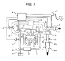
- Fig. 1 is a block diagram of a control device for an engine (internal combustion engine) according to a first embodiment of the present invention.
- the engine control device comprises an engine 19, an air intake system and an exhaust system both attached to the engine 19, and an engine control unit (ECU).
- ECU engine control unit
- the air intake system of the engine 19 includes an air cleaner 17, an air flow sensor 2 for sensing the flow rate of intake air, a compressor 6b of a supercharger, an intercooler 16, a throttle 13 for controlling the intake air flow rate, and an intake air port 20, and they are arranged in the mentioned order from the upstream toward the downstream.
- An intake air pressure sensor 14 is disposed inside or near the intake port 20.
- the exhaust system of the engine 19 includes an exhaust port 26, a ⁇ sensor 3 for sensing the oxygen concentration in exhaust, an exhaust turbine 6a of the supercharger, an exhaust flow rate sensor 12 for directly sensing the exhaust flow rate, a DPF 7 for exhaust purification, and differential pressure sensors 21a and 21b for sensing the difference between pressures upstream and downstream of the DPF 7, and they are arranged in the mentioned order from the upstream toward the downstream along an exhaust pipe 29.
- An exhaust gas recirculation (EGR) passage 9 for recirculating exhaust to the intake port 20 is provided between the exhaust port 26 and the intake port 20 of the engine 19.
- the EGR passage 9 is provided with an EGR cooler 10 and an EGR control valve 11.
- the ECU 8 is connected to an accelerator opening sensor 1, the air flow sensor 2, the ⁇ sensor 3, the compressor 6b, the EGR control valve 11, the exhaust flow rate sensor 12, the throttle 13, and the intake air pressure sensor 14, so that the ECU 8 determines, for the engine 19, the operating condition and the amount of control in accordance with user requests such as the accelerator opening ⁇ and braking condition, vehicle conditions such as traveling speed, and engine conditions such as engine coolant temperature and exhaust temperature.
- the engine 19 is provided with a fuel injection valve (hereinafter referred to as an "injector") 5 for injecting fuel directly into a combustion chamber 18.
- the injector 5 is connected to a fuel tank 15 via a fuel pipe 22.
- Fuel is fed from the fuel tank 15 to the injector 5 through the fuel pipe 22 using a feed pump (not illustrated) provided in the fuel tank 15 and a high-pressure fuel pump (not illustrated) provided between the fuel pipe 22 and the injector 5.
- Fuel is injected into the combustion chamber 18 at prescribed intervals by a required fuel quantity, wherein the required fuel quantity is determined according to a target engine torque calculated based on an opening signal ⁇ from the accelerator opening sensor 1.
- the quantity of fuel to be injected is appropriately corrected according to an opening signal ⁇ tp from the throttle 13, an opening signal ⁇ egr from the EGR control valve 11, boost pressure Ptin of the compressor 6b, and an output value of the ⁇ sensor 3.
- the ⁇ sensor 3 is of a sensor for measuring the air fuel ratio of exhaust from the engine. Instead of the ⁇ sensor 3, an oxygen sensor or CO 2 sensor capable of estimating the oxygen concentration in exhaust may be used as an oxygen concentration estimating device.
- the throttle 13 is preferably an electronically controlled throttle, i.e. a throttle valve driven by an electric actuator.
- the present control device is provided with an exhaust temperature estimating device for sensing or estimating the exhaust temperature.
- the exhaust temperature estimating device may be an exhaust temperature sensor disposed downstream from the DPF 7 to sense the exhaust temperature. It may also be a different type of sensor capable of estimating the exhaust temperature (for example, an exhaust flow rate sensor 12).
- the exhaust flow rate sensor 12 is of a sensor for directly sensing the exhaust flow rate with a sensing period not exceeding one cycle period under various engine operating conditions. It is preferably a hot-wire flow rate sensor or an electromagnetic flow rate sensor, so that the exhaust flow rate can be highly accurately sensed for use in controlling the engine. In the present embodiment, a hot-wire flow rate sensor is used as the exhaust flow rate sensor 12.
- a hot-wire flow rate sensor makes use of two temperature sensitive resistive elements having temperature dependence.
- One of the two temperature sensitive resistive elements is a temperature measuring resistive element for sensing the temperature of a target gas and the other is a heat generating resistive element for sensing which is set to a high temperature relative to the temperature measuring resistive element.
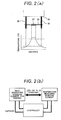
- the temperature sensitive resistive elements used as the heat generating resistive element and temperature measuring resistive element each includes, for example as shown in Fig. 2(a) , a resistance wire (hot wire) 27 wound on a bobbin and lead wires 28 connected to both ends of the resistance wire 27.
- the heat generating resistive element and the temperature measuring resistive element have different resistance values.
- thermosensitive resistive elements are supported by resistive element supports 30 in the exhaust pipe 29.
- the control circuit controls the electric currents applied to the temperature measuring resistive element and heat generating resistive element such that the temperature difference between (or the temperatures of) the two resistive elements becomes constant.
- the gas flow rate is determined based on the quantity of electric current applied to the resistive elements.
- Hot-wire flow rate sensors have good output responsiveness to changes in gas flow rate and most of the intake air flow meters presently used in automobiles are hot-wire flow rate sensors.
- the output characteristic deterioration caused by contamination is a serious problem to be solved for flow rate sensors whether for use in an intake-air environment or in an exhaust environment.
- contaminants such as particulate matter (PM) adhere to a hot wire 27, the output of the flow rate sensor largely varies, and thereby making it impossible to accurately sense the flow rate of gas.
- the hot wire 27 used in the exhaust flow rate sensor 12 is temporarily heated to a temperature at which PM is burned off. This burns off contaminants such as PM adhering to the hot wire 27 and also prevents new contaminants and exhaust condensate water from adhering to the hot wire 27.
- the temperature to which the hot wire 27 is heated to burn off PM is preferably 600°C or higher in view of the Leidenfrost effect that prevents contaminant adherence.
- the flow sensor is, therefore, required to have a structure which can withstand such a high temperature environment, but, since the exhaust condition varies from engine to engine, the temperature is not limited to 600°C or higher.
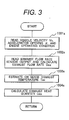
- Fig. 3 is a flowchart for calculating the exhaust heat quantity according to the present embodiment.
- velocity Vc, accelerator opening ⁇ , and engine operating condition as to the vehicle mounted with the engine 19 are read (block 1001s)
- the output value of the exhaust flow rate sensor 12 is read
- exhaust flow rate Qex is calculated based on the data read in (block 1002s).
- exhaust temperature Tex is sensed or estimated (block 1003s) and the exhaust heat quantity Uex is calculated based on exhaust flow rate Qex and exhaust temperature Tex (block 1004s).
- the exhaust heat quantity Uex is calculated using equation (1) shown below.
- Uex Cp ⁇ Qex ⁇ Tex
- Cp is a constant-pressure specific heat of exhaust calculated based on such values as a command value for fuel injection quantity, the output value of the air flow sensor 2, and the output value of the ⁇ sensor 3.
- the constant-pressure specific heat Cp of exhaust can be estimated with high accuracy without differing much from a real value, so that applying an estimated value to the calculation does not result in a large error.
- Exhaust temperature Tex can be calculated based on the output value of the temperature measuring resistive element included in the exhaust flow rate sensor 12 shown in Figs. 2 . Provided that an exhaust temperature sensor is provided in the exhaust pipe 29, the output value of the exhaust temperature sensor may be used.
- An alternative method may also be used in which two heat generating resistive elements with different temperature settings are provided and the exhaust temperature is theoretically determined based on the quantity of power supplied to each of the two heat generating resistive elements and exhaust flow rate Qex sensed by each of the two heat generating resistive elements.
- the control device for an engine can determine the exhaust heat quantity Uex with high accuracy and in a simple manner by calculation based on an exhaust flow rate value directly sensed by the exhaust flow rate sensor 12.
- the ECU 8 may be provided with an engine parameter storage device for storing parameters for controlling the engine 19, and a target quantity of exhaust heat corresponding to each engine operating condition may be set beforehand in the engine parameter storage device. Thereby, the ECU 8 may control the compressor 6(b), inter cooler 16, and throttle 13 or injector 5 so that the exhaust heat quantity estimated based on the output value of the exhaust heat quantity sensor 12 becomes equal to the target exhaust heat quantity.
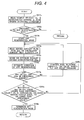
- Fig. 4 is a control flowchart for purifying/regenerating the DPF 7 by using the exhaust flow rate sensor 12 in the control device for an engine according to the present embodiment.
- velocity Vc, accelerator opening ⁇ , and engine operating condition as to the vehicle mounted with the engine 19 are read (block 1011s), and whether to switch the engine operation to DPF regeneration mode is determined (block 1012s).
- the DPF regeneration mode is started (block 1013s).
- exhaust flow rate Qex sensed by the exhaust flow rate sensor 12 or the exhaust heat quantity Uex calculated from Qex is read (block 1014s), exhaust oxygen concentration O 2 ex is estimated or sensed (block 1015s), and the condition of DPF regeneration is estimated (block 1016s).
- Estimating exhaust oxygen concentration O 2 ex in block 1015s is for estimating the quantity of oxidant flowing into the DPF.
- the O 2 ex value is estimated or sensed preferably using a value directly sensed and outputted by the ⁇ sensor 3. It has been known that estimating O 2 ex based on an exhaust oxygen concentration value estimated from the quantity of fuel injection and a value outputted by the air flow sensor 2 does not much affect the error in estimating the exhaust heat quantity.
- Qex or Uex, and O 2 ex are within respective prescribed value ranges.
- engine operation parameters such as fuel injection quantity, opening of the EGR control valve, throttle opening, and boost pressure
- block 1020s engine operation parameters
- the prescribed value ranges are designed to clean (burn off) the soot captured in the DPF 7 at high temperature and, thereby, optimally purify/regenerate the DPF 7. They are set in the ECU 8 beforehand.
- the DPF regeneration mode is terminated (block 1019s).
- Using the flowchart shown in Fig. 4 makes it possible to purify the DPF by accurately supplying a required exhaust heat quantity to the DPF and determine an optimum time of terminating the DPF regeneration mode. This enables engine control without deteriorating exhaust quality or fuel efficiency.
- the regeneration control is performed such a manner that the measuring surface of the sensor is preferably heated to 650°C or higher to thereby burn off or remove contaminants such as soot and soluble organic fractions (SOFs) adheringtothehot-wire surface. This prevents the exhaust flow rate error from enlarging due to performance deterioration of the exhaust flow rate sensor 12, so that the exhaust heat quantity can be accurately determined.
- SOFs soot and soluble organic fractions
- Fig. 5 is a control flowchart for determining malfunction (deterioration) of the exhaust flow rate sensor, performing regeneration control for the DPF 7, and diagnosing the condition of engine operation using the control device according to the present embodiment.
- the exhaust flow rate and the exhaust heat quantity explained with reference up to Fig. 4 represent values determined based on the output value of the exhaust flow rate sensor 12. For this reason, it is necessary to keep monitoring whether the sensing accuracy of the exhaust flow rate sensor 12 is within a prescribed range (i.e. whether the exhaust flow rate sensor 12 is functioning normally) and diagnosing whether the engine is operating in desired condition.
- velocity Vc, accelerator opening ⁇ , and engine operating condition as to the vehicle mounted with the engine 19 are read (block 1021s), the output values of the air flow sensor 2 and the exhaust flow rate sensor 12 are read (block 1022s), and whether or not the engine 19 is operating in a steady state is determined (block 1023s).
- the procedure for diagnosing and determining the operating condition of the engine according to this flowchart cannot be performed during a transient period of engine operation.
- exhaust flaw rate Qex' estimated, for example, based on the output value of the air flow sensor 2 and the quantity of fuel injection is read (block 1024s), and exhaust flaw rate Qex is calculated based on a normative value directly sensed and outputted by the exhaust flow rate sensor 12 (block 1025s).
- the present embodiment is provided with: a first exhaust heat quantity estimating device for estimating a first exhaust flow rate Qex based on an output value of the exhaust flow rate directly sensed with the exhaust flow rate sensor 12 and the exhaust temperature; and a second exhaust heat quantity estimating device for estimating a second exhaust flow rate Qex' based on an output value of the air flow rate sensed by the air flow sensor 2 and the exhaust temperature.
- Qex' and Qex are compared to each other, the comparing is used for determining malfunction of the exhaust flow rate sensor 12, controlling DPF regeneration, and diagnosing the condition of engine operation.
- the estimation of the exhaust flow rate in block 1024s is for determining whether or not the output value of the exhaust flow rate sensor 12 is normal, so that it may be replaced by the exhaust flow rate Qex' estimated based on the output value of the intake air pressure sensor 14, the opening of the throttle 13, and the opening of the EGR control valve 11.
- the absolute value of difference therebetween exceeds a prescribed value therefor (block 1026s ⁇ Yes)
- determination is done as to whether or not the exhaust flow sensor 12 is malfunctioning (block 1027s).
- the determination of malfunction is preferably done based on diagnosis which is done by real time-analyzing of changes in current-carrying characteristics or by real time-analyzing output waveforms (real-time determination of engine operating condition). But a different method may also be used as long as malfunctioning of the exhaust flow rate sensor 12 can be determined.
- the exhaust flow rate sensor 12 When the exhaust flow rate sensor 12 is determined to be malfunctioning (1027s ⁇ Yes), the output value of the exhaust flow rate sensor 12 cannot subsequently be used in estimating the exhaust flow rate, so that Qex' is used as an estimated exhaust flow rate (block 1033s). Based on the estimated exhaust flow rate Qex', the exhaust heat quantity Uex' is calculated (block 1034s) and the calculated exhaust heat quantity is used to control the engine 19 and the DPF regeneration mode.
- exhaust oxygen concentration O 2 ex is estimated, for example, from the output value of the ⁇ sensor 3, and whether or not the estimated value is equal to or lower than the corresponding prescribed value is determined therefor(block 1028s).
- O 2 ex is determined to be equal to or lower than the prescribed value (1028s ⁇ Yes)
- it can be determined that the quantity of oxygen contained in exhaust is smaller than usual. This indicates that the quantity or proportion of blow-by gas contained in exhaust has increased.
- the exhaust oxygen concentration O 2 ex is determined to be higher than the corresponding prescribed value therefor (1028s ⁇ No), it is determined that the exhaust flow rate sensor 12 is temporarily malfunctioning, for example, due to contamination.
- Flow rate sensing by the exhaust flow rate sensor 12 is then stopped (block 1029s) and regeneration control for the exhaust flow rate sensor is performed as described above (block 1030s).
- the regeneration control is performed by setting the measuring surface of the sensor at preferably 650°C of heating temperature or higher so as to burn off or remove contaminants such as soot and soluble organic fractions (SOFs) adhering to the hot-wire surface.
- the control device for an engine can appropriately determine the conditions of the engine and the exhaust flow rate sensor 12 based on the flowchart shown in Fig. 5 so as to allow the engine to continue operation without largely deteriorating engine performance indicated by exhaust quality and fuel efficiency.
- Acontrol device for an engine according to a second embodiment of the present invention will be described below.
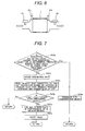
- Fig. 6 is a cross-sectional schematic diagram of an essential part of the exhaust pipe 29 according to the second embodiment in the vicinity of the DPF 7.
- the engine control device of the second embodiment differs from that of the first embodiment in that it has an exhaust flow rate sensor 24 disposed downstream of the DPF 7 in addition to the exhaust flow sensor disposed upstream of the DPF 7.
- the exhaust flow rate sensor 24 may be installed instead of the exhaust temperature sensor.
- Fig. 7 is a flowchart of a method of diagnosing the DPF using the control device for an engine according to the present embodiment.
- Block 1018s shown in Fig. 7 is the same as block 1018s shown in Fig. 4 . Namely, when the integrated value of Qex or Uex is larger than the prescribed value therefor or when the output value of the differential pressure sensor 21a or 21b is equal to or lower than the prescribed value , it is determined that the DPF has been adequately regenerated and the DPF regeneration mode is terminated (1018 ⁇ Yes).
- Uex determined based on the output value of the exhaust flow rate sensor 12 disposed (immediately) upstream of the DPF 7 and Uex" determined based on the output value of the exhaust flow rate sensor 24 disposed (immediately) downstream of the DPF 7 are read (block 1042s), and whether or not the difference between Uex and Uex" is larger than the corresponding prescribed value is determined (block 1043s).
- block 1043s the difference between Uex and Uex" is larger than the prescribed value therefor (1043s ⁇ Yes)
- the exhaust flow rate sensor 24 is installed downstream of the DPF 7. Using the output values of these exhaust flow rate sensors makes it possible to accurately diagnose the condition of the DPF 7 and prevent deterioration of exhaust quality.
- the DPF 7 can be diagnosed as shown in Fig. 7 by applying the above calculated value Qex' or Uex'.
- the present invention is effective also when a catalyst (for example, NOx or SCR) for which direct sensing of an exhaust flow rate and exhaust heat calculation is effective is used and can contribute for the purpose of purifying exhaust from such an engine system.
- a catalyst for example, NOx or SCR
Landscapes
- Engineering & Computer Science (AREA)
- Chemical & Material Sciences (AREA)
- Combustion & Propulsion (AREA)
- Mechanical Engineering (AREA)
- General Engineering & Computer Science (AREA)
- Processes For Solid Components From Exhaust (AREA)
- Exhaust Gas After Treatment (AREA)
- Combined Controls Of Internal Combustion Engines (AREA)
- Electrical Control Of Air Or Fuel Supplied To Internal-Combustion Engine (AREA)
Applications Claiming Priority (2)
| Application Number | Priority Date | Filing Date | Title |
|---|---|---|---|
| JP2008242453A JP4929261B2 (ja) | 2008-09-22 | 2008-09-22 | エンジンの制御装置 |
| PCT/JP2009/003494 WO2010032356A1 (fr) | 2008-09-22 | 2009-07-24 | Dispositif de commande pour moteur |
Publications (1)
| Publication Number | Publication Date |
|---|---|
| EP2330285A1 true EP2330285A1 (fr) | 2011-06-08 |
Family
ID=42039209
Family Applications (1)
| Application Number | Title | Priority Date | Filing Date |
|---|---|---|---|
| EP09814202A Withdrawn EP2330285A1 (fr) | 2008-09-22 | 2009-07-24 | Dispositif de commande pour moteur |
Country Status (4)
| Country | Link |
|---|---|
| US (1) | US8290685B2 (fr) |
| EP (1) | EP2330285A1 (fr) |
| JP (1) | JP4929261B2 (fr) |
| WO (1) | WO2010032356A1 (fr) |
Families Citing this family (9)
| Publication number | Priority date | Publication date | Assignee | Title |
|---|---|---|---|---|
| JP6144568B2 (ja) * | 2013-07-31 | 2017-06-07 | いすゞ自動車株式会社 | センサ出力値推定装置 |
| KR101497828B1 (ko) * | 2013-09-30 | 2015-03-02 | 두산엔진주식회사 | 선택적 촉매 환원 시스템 및 선택적 촉매 환원 방법 |
| KR101497833B1 (ko) * | 2013-10-11 | 2015-03-02 | 두산엔진주식회사 | 선택적 촉매 환원 시스템 |
| JP6404030B2 (ja) * | 2014-08-12 | 2018-10-10 | 株式会社堀場製作所 | 排ガス測定用情報処理装置、排ガス測定システム及びプログラム |
| WO2017023758A1 (fr) * | 2015-08-05 | 2017-02-09 | Cummins Emission Solutions Inc. | Correction d'oxygène pour estimations de nox en sortie de moteur à l'aide de capteur de nox de système de post-traitement |
| JP6365501B2 (ja) * | 2015-10-21 | 2018-08-01 | 株式会社デンソー | 粒子状物質検出装置 |
| GB2555437B (en) * | 2016-10-27 | 2019-09-11 | Ford Global Tech Llc | A method of cleaning an exhaust gas recirculation valve |
| US11286835B2 (en) | 2017-05-25 | 2022-03-29 | Cummins Emission Solutions Inc. | System and methods for controlling flow distribution in an aftertreatment system |
| KR102429067B1 (ko) * | 2017-12-27 | 2022-08-04 | 현대자동차주식회사 | 에어 플로우 센서의 오측정 방지 방법 |
Family Cites Families (22)
| Publication number | Priority date | Publication date | Assignee | Title |
|---|---|---|---|---|
| JP3161249B2 (ja) * | 1994-11-02 | 2001-04-25 | 日産自動車株式会社 | 内燃機関の触媒劣化診断装置 |
| JP3408754B2 (ja) * | 1998-10-02 | 2003-05-19 | 本田技研工業株式会社 | 内燃機関の回転数制御装置 |
| JP3800324B2 (ja) * | 2001-11-13 | 2006-07-26 | 三菱自動車工業株式会社 | 筒内噴射型火花点火式内燃機関の排気浄化装置 |
| DE10100419A1 (de) * | 2001-01-08 | 2002-07-11 | Bosch Gmbh Robert | Verfahren und Vorrichtung zur Steuerung eines Abgasnachbehandlungssystems |
| JP3838339B2 (ja) * | 2001-03-27 | 2006-10-25 | 三菱ふそうトラック・バス株式会社 | 内燃機関の排気浄化装置 |
| US6898927B2 (en) * | 2001-10-16 | 2005-05-31 | Denso Corporation | Emission control system with catalyst warm-up speeding control |
| JP4062729B2 (ja) * | 2001-11-05 | 2008-03-19 | 株式会社デンソー | 触媒早期暖機システムの異常診断装置 |
| JP2003254038A (ja) | 2002-03-04 | 2003-09-10 | Toyota Motor Corp | 内燃機関の排気浄化装置 |
| JP2006063905A (ja) * | 2004-08-27 | 2006-03-09 | Toyota Motor Corp | パティキュレートフィルタの粒子状物質残量推定方法およびパティキュレートフィルタの再生方法 |
| US6993428B1 (en) * | 2004-09-22 | 2006-01-31 | International Engine Intellectual Property Company, Llc | Detecting leakage of engine exhaust gas using exhaust mass flow measurement |
| JP2006170004A (ja) * | 2004-12-14 | 2006-06-29 | Mitsubishi Motors Corp | 内燃機関の空燃比制御装置 |
| EP1856386A1 (fr) * | 2005-02-16 | 2007-11-21 | Imi Vision Limited | Traitement de gaz d'echappement |
| JP2006242072A (ja) * | 2005-03-02 | 2006-09-14 | Mitsubishi Fuso Truck & Bus Corp | 内燃機関の排気浄化装置 |
| JP4631664B2 (ja) * | 2005-11-18 | 2011-02-16 | 株式会社デンソー | ガスセンサのヒータ制御装置 |
| DE102006009241A1 (de) * | 2006-02-28 | 2007-09-06 | Siemens Ag | Verfahren und Vorrichtung zum Betreiben einer Brennkraftmaschine |
| DE102006050560A1 (de) * | 2006-06-03 | 2007-12-06 | Bayerische Motoren Werke Ag | Betriebsverfahren für ein System aus einem Reformer und einer katalytischen Abgas-Nachbehandlungsvorrichtung |
| JP2008088962A (ja) * | 2006-10-05 | 2008-04-17 | Mitsubishi Motors Corp | 触媒熱劣化判定装置及び触媒熱劣化抑制装置 |
| US7824099B2 (en) * | 2007-11-29 | 2010-11-02 | Gm Global Technology Operations, Inc. | Accurate gas temperature estimation at transient conditions based on temperature sensor readings |
| US8061138B2 (en) * | 2008-06-24 | 2011-11-22 | Ford Global Technologies, Llc | System for controlling contaminant deposition in exhaust gas recirculation coolers |
| JP5191361B2 (ja) * | 2008-11-21 | 2013-05-08 | 株式会社日立製作所 | 液位制御システム。 |
| US8211300B2 (en) * | 2008-12-22 | 2012-07-03 | Exxonmobil Research And Engineering Company | Vehicle-mounted fuel separation system |
| US8423269B2 (en) * | 2009-07-08 | 2013-04-16 | Cummins Inc. | Exhaust gas recirculation valve contaminant removal |
-
2008
- 2008-09-22 JP JP2008242453A patent/JP4929261B2/ja not_active Expired - Fee Related
-
2009
- 2009-07-24 EP EP09814202A patent/EP2330285A1/fr not_active Withdrawn
- 2009-07-24 US US12/920,558 patent/US8290685B2/en not_active Expired - Fee Related
- 2009-07-24 WO PCT/JP2009/003494 patent/WO2010032356A1/fr not_active Ceased
Non-Patent Citations (1)
| Title |
|---|
| See references of WO2010032356A1 * |
Also Published As
| Publication number | Publication date |
|---|---|
| JP2010071257A (ja) | 2010-04-02 |
| JP4929261B2 (ja) | 2012-05-09 |
| US20110166768A1 (en) | 2011-07-07 |
| WO2010032356A1 (fr) | 2010-03-25 |
| US8290685B2 (en) | 2012-10-16 |
Similar Documents
| Publication | Publication Date | Title |
|---|---|---|
| US8290685B2 (en) | Control device for engine | |
| US7681560B2 (en) | Exhaust gas recirculation system | |
| WO2006092946A1 (fr) | Dispositif de controle des emissions d’echappement et moteur a combustion interne equipe dudit dispositif et procede de regeneration de filtre a particules | |
| JP4709220B2 (ja) | パティキュレートフィルタの再生方法 | |
| CN101896700A (zh) | 用于诊断颗粒过滤器的方法和装置 | |
| BR112016001303B1 (pt) | Sistema de controle de emissão de escapamento para motor de combustão interna e método de controle para sistema de controle de emissão de escapamento para motor de combustão interna | |
| EP2400136B1 (fr) | Détecteur pour moteur à combustion interne | |
| JP2010116857A (ja) | エアフロセンサの異常診断装置及び異常診断方法 | |
| JP2007247596A (ja) | 内燃機関の排気浄化装置 | |
| JP2010196498A (ja) | Pm排出量推定装置 | |
| JP2008069690A (ja) | 排ガス還流制御装置 | |
| JP4341460B2 (ja) | 内燃機関用排気ガス浄化装置 | |
| JP2011247195A (ja) | 内燃機関の排気浄化装置 | |
| JP3646635B2 (ja) | 内燃機関の排気浄化装置 | |
| JP4556800B2 (ja) | エンジンの背圧制御装置 | |
| JP5136465B2 (ja) | 内燃機関の排気浄化装置 | |
| JP2009299652A (ja) | 内燃機関の制御装置及び制御方法 | |
| JP4894569B2 (ja) | 温度センサの故障診断装置 | |
| JP2008231951A (ja) | エンジンの排気温度推定装置及びエンジンの排気浄化装置 | |
| JP2021173218A (ja) | 触媒劣化度推定装置 | |
| JP2007064112A (ja) | 還元剤供給装置の診断装置 | |
| JP7302541B2 (ja) | 排気処理システム | |
| JP2015007386A (ja) | 異常検出装置 | |
| JP4539466B2 (ja) | 内燃機関の排気浄化システム | |
| JP6962262B2 (ja) | 排気処理システム |
Legal Events
| Date | Code | Title | Description |
|---|---|---|---|
| PUAI | Public reference made under article 153(3) epc to a published international application that has entered the european phase |
Free format text: ORIGINAL CODE: 0009012 |
|
| 17P | Request for examination filed |
Effective date: 20110426 |
|
| AK | Designated contracting states |
Kind code of ref document: A1 Designated state(s): AT BE BG CH CY CZ DE DK EE ES FI FR GB GR HR HU IE IS IT LI LT LU LV MC MK MT NL NO PL PT RO SE SI SK SM TR |
|
| AX | Request for extension of the european patent |
Extension state: AL BA RS |
|
| DAX | Request for extension of the european patent (deleted) | ||
| STAA | Information on the status of an ep patent application or granted ep patent |
Free format text: STATUS: THE APPLICATION HAS BEEN WITHDRAWN |
|
| 18W | Application withdrawn |
Effective date: 20160303 |