EP2330346A2 - Temperaturfühler für einen Brenner und Brenner - Google Patents
Temperaturfühler für einen Brenner und Brenner Download PDFInfo
- Publication number
- EP2330346A2 EP2330346A2 EP11159949A EP11159949A EP2330346A2 EP 2330346 A2 EP2330346 A2 EP 2330346A2 EP 11159949 A EP11159949 A EP 11159949A EP 11159949 A EP11159949 A EP 11159949A EP 2330346 A2 EP2330346 A2 EP 2330346A2
- Authority
- EP
- European Patent Office
- Prior art keywords
- sensor
- burner
- head
- wall
- seat
- Prior art date
- Legal status (The legal status is an assumption and is not a legal conclusion. Google has not performed a legal analysis and makes no representation as to the accuracy of the status listed.)
- Withdrawn
Links
Images




Classifications
-
- F—MECHANICAL ENGINEERING; LIGHTING; HEATING; WEAPONS; BLASTING
- F23—COMBUSTION APPARATUS; COMBUSTION PROCESSES
- F23D—BURNERS
- F23D14/00—Burners for combustion of a gas, e.g. of a gas stored under pressure as a liquid
- F23D14/46—Details
- F23D14/72—Safety devices, e.g. operative in case of failure of gas supply
- F23D14/725—Protection against flame failure by using flame detection devices
-
- F—MECHANICAL ENGINEERING; LIGHTING; HEATING; WEAPONS; BLASTING
- F23—COMBUSTION APPARATUS; COMBUSTION PROCESSES
- F23N—REGULATING OR CONTROLLING COMBUSTION
- F23N5/00—Systems for controlling combustion
- F23N5/02—Systems for controlling combustion using devices responsive to thermal changes or to thermal expansion of a medium
- F23N5/10—Systems for controlling combustion using devices responsive to thermal changes or to thermal expansion of a medium using thermocouples
-
- G—PHYSICS
- G01—MEASURING; TESTING
- G01K—MEASURING TEMPERATURE; MEASURING QUANTITY OF HEAT; THERMALLY-SENSITIVE ELEMENTS NOT OTHERWISE PROVIDED FOR
- G01K1/00—Details of thermometers not specially adapted for particular types of thermometer
- G01K1/14—Supports; Fastening devices; Arrangements for mounting thermometers in particular locations
- G01K1/143—Supports; Fastening devices; Arrangements for mounting thermometers in particular locations for measuring surface temperatures
-
- G—PHYSICS
- G01—MEASURING; TESTING
- G01K—MEASURING TEMPERATURE; MEASURING QUANTITY OF HEAT; THERMALLY-SENSITIVE ELEMENTS NOT OTHERWISE PROVIDED FOR
- G01K7/00—Measuring temperature based on the use of electric or magnetic elements directly sensitive to heat ; Power supply therefor, e.g. using thermoelectric elements
- G01K7/02—Measuring temperature based on the use of electric or magnetic elements directly sensitive to heat ; Power supply therefor, e.g. using thermoelectric elements using thermoelectric elements, e.g. thermocouples
- G01K7/04—Measuring temperature based on the use of electric or magnetic elements directly sensitive to heat ; Power supply therefor, e.g. using thermoelectric elements using thermoelectric elements, e.g. thermocouples the object to be measured not forming one of the thermoelectric materials
-
- F—MECHANICAL ENGINEERING; LIGHTING; HEATING; WEAPONS; BLASTING
- F23—COMBUSTION APPARATUS; COMBUSTION PROCESSES
- F23D—BURNERS
- F23D2203/00—Gaseous fuel burners
- F23D2203/10—Flame diffusing means
- F23D2203/101—Flame diffusing means characterised by surface shape
- F23D2203/1012—Flame diffusing means characterised by surface shape tubular
-
- F—MECHANICAL ENGINEERING; LIGHTING; HEATING; WEAPONS; BLASTING
- F23—COMBUSTION APPARATUS; COMBUSTION PROCESSES
- F23D—BURNERS
- F23D2208/00—Control devices associated with burners
- F23D2208/10—Sensing devices
-
- F—MECHANICAL ENGINEERING; LIGHTING; HEATING; WEAPONS; BLASTING
- F23—COMBUSTION APPARATUS; COMBUSTION PROCESSES
- F23D—BURNERS
- F23D2209/00—Safety arrangements
- F23D2209/20—Flame lift-off / stability
-
- F—MECHANICAL ENGINEERING; LIGHTING; HEATING; WEAPONS; BLASTING
- F23—COMBUSTION APPARATUS; COMBUSTION PROCESSES
- F23N—REGULATING OR CONTROLLING COMBUSTION
- F23N2225/00—Measuring
- F23N2225/08—Measuring temperature
- F23N2225/16—Measuring temperature burner temperature
-
- F—MECHANICAL ENGINEERING; LIGHTING; HEATING; WEAPONS; BLASTING
- F23—COMBUSTION APPARATUS; COMBUSTION PROCESSES
- F23N—REGULATING OR CONTROLLING COMBUSTION
- F23N2900/00—Special features of, or arrangements for controlling combustion
- F23N2900/05005—Mounting arrangements for sensing, detecting or measuring devices
Definitions
- the present invention relates to a temperature sensor for burners and to a burner provided with such temperature sensor.
- the present invention relates to a thermocouple temperature sensor intended to be connected to a surface of a burner, for example, a gas burner, for industrial and domestic applications.
- One of the several uses of the above-mentioned burners is that of the instantaneous or non-instantaneous heaters to heat a fluid, for example, water, which is subsequently conveyed to a use, for example, a heating system of an industrial process, housing environments, or the like.
- a fluid for example, water
- thermocouple sensor welded to an outer surface of a burning wall of the burner ( Fig. 3B ) within the combustion chamber in such a position as to be directly lapped by the combusted fluids.
- the accuracy and repeatability of such measurement is hindered by the accuracy required in positioning the thermocouple, since a displacement of the sensor of one tenth of millimetre relative to the correct position thereof can involve a variation of the detected temperature of tens of degrees.
- the cables constituting the temperature sensor that are located within the combustion chamber in the flow of the combusted fluids and in the generated flames are subjected to a high degradation, due to the temperatures and temperature variations to which it is subjected.
- a further known system for the measurement of the temperature of burners provides for a temperature sensor welded to an inner surface of a burning wall of the burner ( Fig. 3A ). This involves a reduction of the sensor degradation thanks to the moving away of the cables constituting it from the hottest zones within the burner.
- the temperature value detected is always sensitive to positioning errors of the sensor.
- a displacement of the sensor of one millimetre relative to the correct position thereof can involve a variation of the detected temperature of tens of degrees.
- the thermocouple temperature sensor that is welded on the inner surface of the burning wall of the burner ( Fig. 3B ) cannot be freely positioned at any point, but an appropriate accessibility is necessary for the assembling, which often limits the positioning choices for the thermocouple. This makes these systems not very efficient for a combustion control in boilers requiring an instantaneous and accurate response of the thermal sensor, and which therefore have to be positioned at the area of the burning surface.
- thermocouple sensor connection provides that the thermocouple two metal wires are directly welded on the burner wall inner surface, opposite the inner space of the combustion chamber in which the flames are generated ( Figs. 3 and 3A ).
- thermocouple metal wires are welded to the burner wall inner surface so as to implement extensions or spacers to which the thermocouple sensor metal wires are welded.
- Such rigid bars can be welded on the burner wall inner surface ( Fig. 4 ), or they could project inwardly of the combustion chamber and be secured to the burner wall by means of welding operations (outer surface side, or in other terms, "burning surface” of the burner wall) that are directly exposed to the combustion environment ( Fig. 5 ).
- the two metal wires of the thermocouple sensor for burners are protected by an insulating sheath of flexible material that makes even more difficult a correct positioning of the metal wires during the connection by welding thereof.
- the flexible sheaths in plastic material or glass fibre/resin are not suitable to resist to the temperatures within the burner; the flexible sheaths in ceramic material, even though they are resistant to the temperatures, however do not ensure a suitable electric insulation of the metal wires.
- the object of the present invention is to provide a temperature sensor for burners having characteristics such as to allow a positioning thereof with high accuracy and to obviate deformations and degradation of the sensor or parts thereof.
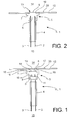
- a temperature sensor for a burner is generally indicated with the reference 1.
- the sensor 1 comprises two metal wires 2, 3 that are suitable to implement a thermocouple (Seebeck effect), a protection sheath 4 receiving and wrapping the two metal wires 2, 3, as well as a head 5 in metal material.
- a thermocouple Seebeck effect
- a protection sheath 4 receiving and wrapping the two metal wires 2, 3, as well as a head 5 in metal material.
- the head 5 has a front side 14 intended to be facing the environment, the temperature of which is intended to be measured, and a rear side 15 opposite the front side 14 and to which the two metal wires 2, 3 are connected in a thermal exchange relationship with the head 5.
- the head 5 comprises a front portion 6 intended to be inserted in a sensor seat 13 of a burner wall 12 of the burner, as well as at least one first positioning surface 16 and at least one second positioning surface 18.
- the first positioning surface 16 is configured and suitable to engage an inner surface 17 of the sensor seat 13 so as to prevent displacements of the head 5 in the plane of the burner wall 12, and the second positioning surface 18 is transversal to the first positioning surface 16 and so formed as to be able to engage the burner wall 12 in the proximity of the sensor seat 13 to prevent displacements of the head 5 in the transversal direction to the burner wall 12 plane.
- the first and second positioning surfaces 16, 18 of the head 5 advantageously implement reliable references for an easy and accurate positioning of the temperature sensor in the burner.
- the front portion 6 comprises a measurement front surface 19 intended to be exposed to the environment, the temperature of which is intended to be measured, and/or suitable to complete and constitute the surface, the temperature of which is intended to be measured, and the first positioning surface 16 extends transversally to such measurement surface 19.
- the head 5 may comprise a shoulder 7 forming an abutment surface facing the front side 14, thus implementing the above-mentioned second positioning surface 18.
- the front portion 6 is formed in relief relative to the shoulder 7 and comprises an annular side surface 16 that is substantially perpendicular to the measurement front surface 19 so as to form a step between the measurement front surface 19 and the abutment surface (second positioning surface) 18.
- the annular side surface 16 implements the above-mentioned first positioning surface.
- the measurement surface 19, the first positioning surface 16, and the second positioning surface 18 are substantially mutually centred and preferably coaxial.
- the measurement surface 19 is preferably substantially planar and parallel to the second positioning surface 18. This allows positioning the temperature sensor head so that the measurement surface 19 thereof is parallel and aligned flush with a burning surface 20 of the burner wall 12 or, if it is desired and useful to the aims of the measurement, a positioning of the temperature sensor head can be obtained, so that the measurement surface 19 thereof projects by an extremely accurate and repeatable length.
- thermocouple seats 10 are advantageously formed, 11 for the connection by welding of the two metal wires 2, 3.
- the thermocouple seats can be made by means of two holes spaced one from the other, so that each of the two metal wires is separately welded to the head 5.
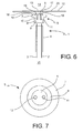
- the head can comprise thermocouple seats 10, 11, 10', 11' formed as blind holes ( Fig. 1 ), or preferably as through holes ( Fig. 6 ), and a single head 5 can comprise a plurality of thermocouple seats 10, 11, 10', 11' to receive 2 or more metal wires of one or more thermocouples.
- the head 5 comprises a preferably cylindrical annular wall 9 on the rear side 15 thereof, defining internally a sheath seat 8 to receive a front end of the protection sheath 4.
- thermocouple seats 10, 11 can be advantageously formed within the sheath seat 8, so that the connection between the head 5 and the metal wires 2, 3 is protected and encapsulated within the sheath seat 8, the rear opening of which results to be stopped up by the sheath itself, which can be connected to the head 5 by a shape or interference connection, for example, by clamping or crimping, or welding of the annular wall 9 to or about the protection sheath 4 front end.
- the sheath itself is advantageously in a thermoresistant and substantially rigid material, such as to protect the metal wires and to facilitate the assembling of the sensor 1 to the burner.
- the sheath can be manufactured in a metal and/or plastic and/or silicon and/or ceramic material, optionally containing mineral fibres to increase the thermoinsulating characteristics thereof and also the mechanical rigidity thereof.
- the sheath 4 comprises a mineral insulated cable.
- the metal wires can be selected (by way of non-limiting example) as follows:
- the sensor 1 head 5 has a substantially rotation body shape, except for the thermocouple seats 10, 11 for the connection of the metal wires 2, 3.
- the present invention also relates to a burner, for example, a burner of a heating device in general, or of a boiler with a combustion chamber having a burner wall 12 the outer surface of which implements a burning surface 20 at which the temperature is measured by the temperature sensor 1 hereto described and illustrated.
- a burner for example, a burner of a heating device in general, or of a boiler with a combustion chamber having a burner wall 12 the outer surface of which implements a burning surface 20 at which the temperature is measured by the temperature sensor 1 hereto described and illustrated.
- a through opening forming the sensor seat 13 is implemented, for example, by punching or moulding, in the burner wall 12.
- the front portion 6 the head is advantageously obtained by turning or moulding
- the latter results to be insertable and positionable in the sensor seat 13 with a high accuracy.
- the burner wall 12 thickness and the front portion 6 length are selected so that the sensor measurement surface 19 is arranged flush with the burner wall 12 burning surface 20 to implement a substantial surface continuity of such burning surface 20.
- the burner wall 12 thickness and the front portion 6 length are selected so that the sensor measurement surface 19 projects in an accurate and repeatable manner relative to the burner wall 12 burning surface 20.
- the sensor 1 head 5, in particular the front portion 6 thereof is of the same material of the burning surface 20.
- the head 5 is welded to the burner wall 12, preferably by laser welding or the like, in which the sensor seat 13 inner surface 17 and a corresponding surface of the head 5 facing thereto (preferably, the first positioning surface 16) are melted and welded one to the other so as to connect the head and the burner wall and to create a continuity of material of the burner wall at the sensor seat.
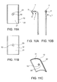
- the front portion 6 has a substantially rotation body shape (for example, a cylindrical or frusto-conical shape) so as to be able to be rotatably inserted in the burner wall 12 sensor seat 13 (having a shape that is substantially complementary to the front portion 6 shape), and the shoulder 7 has an elongated shape (for example, substantially oval) in a transversal direction to the insertion direction of the head 5 in the burner wall 12 sensor seat 13.
- a substantially rotation body shape for example, a cylindrical or frusto-conical shape
- the shoulder 7 has an elongated shape (for example, substantially oval) in a transversal direction to the insertion direction of the head 5 in the burner wall 12 sensor seat 13.
- the distribution wall 21 can comprise a locking opening 23 that is substantially aligned with the burner wall 12 sensor seat 13 and having a shape such as to allow the passage (inlet and outlet) of the shoulder 7 in a angular release position ( Fig. 12 ) and to prevent the passage of the shoulder 7 (outlet and inlet) in at least one angular locking position ( Fig. 13 ) different from the angular release position.
- the distribution wall 21 locking opening 23 has a shape substantially complementary to the elongated, preferably oval, shape of the shoulder 7.
- the shoulder 7 engages by interference the curved burner 12 and distribution 21 walls, and it is locked therebetween.
- the shoulder 7 rear peripheral edge 25 (facing away from the front portion 6) has a bevel that allows the shoulder to slip by interference under the distribution wall 21 during the rotation from the release position to the locking position.
- an outer spring clip 24 can be further provided, which is connected to the burner and suitable to engage the sensor 1 in the locking position and oppose to undesired rotations of the sensor 1.
- the temperature sensor and the burner containing such sensor have a number of advantages.
- the sheath-thermocouple-metal head assembly of the sensor 1 constitute an easily positionable component within the burner and securable therein with high positioning accuracy.
- the sensor and the burner with the sensor allow protecting the thermocouple against oxidation phenomena of the welded joints, prevent displacements, mispositioning, and undesired deformations of the measurement surface (hot side of the thermocouple), and allow reducing the thermal inertia of the temperature measurement system.
- the senor and the burner according to the invention allow the measurement of the temperature of a burning surface of the burner, and at the same time they ensure the continuity of surface of such burning surface.
Landscapes
- Engineering & Computer Science (AREA)
- Physics & Mathematics (AREA)
- General Physics & Mathematics (AREA)
- Chemical & Material Sciences (AREA)
- Combustion & Propulsion (AREA)
- Mechanical Engineering (AREA)
- General Engineering & Computer Science (AREA)
- Control Of Combustion (AREA)
Applications Claiming Priority (2)
| Application Number | Priority Date | Filing Date | Title |
|---|---|---|---|
| ITMI2008A001886A IT1393070B1 (it) | 2008-10-24 | 2008-10-24 | Termocoppia speciale per bruciatori |
| EP09173287A EP2180253A1 (de) | 2008-10-24 | 2009-10-16 | Temperaturfühler für einen Brenner und Brenner |
Related Parent Applications (2)
| Application Number | Title | Priority Date | Filing Date |
|---|---|---|---|
| EP09173287.5 Division | 2009-10-16 | ||
| EP09173287A Division EP2180253A1 (de) | 2008-10-24 | 2009-10-16 | Temperaturfühler für einen Brenner und Brenner |
Publications (2)
| Publication Number | Publication Date |
|---|---|
| EP2330346A2 true EP2330346A2 (de) | 2011-06-08 |
| EP2330346A3 EP2330346A3 (de) | 2017-09-27 |
Family
ID=41264200
Family Applications (2)
| Application Number | Title | Priority Date | Filing Date |
|---|---|---|---|
| EP11159949.4A Withdrawn EP2330346A3 (de) | 2008-10-24 | 2009-10-16 | Temperaturfühler für einen Brenner und Brenner |
| EP09173287A Withdrawn EP2180253A1 (de) | 2008-10-24 | 2009-10-16 | Temperaturfühler für einen Brenner und Brenner |
Family Applications After (1)
| Application Number | Title | Priority Date | Filing Date |
|---|---|---|---|
| EP09173287A Withdrawn EP2180253A1 (de) | 2008-10-24 | 2009-10-16 | Temperaturfühler für einen Brenner und Brenner |
Country Status (3)
| Country | Link |
|---|---|
| US (1) | US8353627B2 (de) |
| EP (2) | EP2330346A3 (de) |
| IT (1) | IT1393070B1 (de) |
Cited By (2)
| Publication number | Priority date | Publication date | Assignee | Title |
|---|---|---|---|---|
| IT201900003507A1 (it) | 2019-03-11 | 2020-09-11 | Polidoro S P A | Sensore di temperatura perfezionato per bruciatore a gas e assieme di un tale sensore e bruciatore |
| EP4123241A1 (de) | 2021-07-22 | 2023-01-25 | BDR Thermea Group B.V. | System und verfahren zur erfassung des rückflusses einer flüssigkeit in einer brennkammer eines heizkessels |
Families Citing this family (10)
| Publication number | Priority date | Publication date | Assignee | Title |
|---|---|---|---|---|
| EP1898195B1 (de) * | 2006-09-06 | 2010-07-14 | Kistler Holding AG | Temperatursensor mit bearbeitbarer Front |
| IT1393070B1 (it) * | 2008-10-24 | 2012-04-11 | Worgas Bruciatori Srl | Termocoppia speciale per bruciatori |
| EP2649372B1 (de) * | 2010-12-09 | 2015-02-11 | Bekaert Combustion Technology B.V. | Brenner mit lokal fixiertem brennerdeck |
| KR101967006B1 (ko) * | 2011-05-06 | 2019-04-08 | 베카에르트 컴버스천 테크놀러지 비.브이. | 온도 측정 기능을 갖춘 예혼합 가스 버너 |
| US20130255658A1 (en) * | 2012-03-30 | 2013-10-03 | Timothy Scott Shaffer | Sealed instrumentation port on ceramic cooktop |
| US10018363B1 (en) * | 2016-12-23 | 2018-07-10 | Jade Range LLC | Hearth oven |
| EP3514515B1 (de) * | 2018-01-18 | 2020-03-04 | Samsung SDI Co., Ltd. | Thermoelement und verfahren zur herstellung des thermoelements |
| DE102018108240A1 (de) * | 2018-04-06 | 2019-10-10 | Alinox Ag | Verfahren zum Herstellen einer Metallplatte mit eingebettetem Temperatursensor, sowie danach hergestellte Metallplatte |
| CN114304745A (zh) * | 2020-09-29 | 2022-04-12 | 深圳市合元科技有限公司 | 用于气雾生成装置的感受器、气雾生成装置及测温装置 |
| US20250290804A1 (en) * | 2024-03-12 | 2025-09-18 | Rosemount Inc. | Non-welded thermocouple assembly |
Family Cites Families (27)
| Publication number | Priority date | Publication date | Assignee | Title |
|---|---|---|---|---|
| GB957429A (en) * | 1959-08-18 | 1964-05-06 | Honeywell Regulator Co | Improvements in thermocouples |
| US4767468A (en) * | 1984-07-02 | 1988-08-30 | Finney Philip F | Thermocouple assembly |
| US4765183A (en) * | 1987-03-12 | 1988-08-23 | Coury Glenn E | Apparatus and method for taking measurements while drilling |
| EP0338101A1 (de) * | 1988-04-19 | 1989-10-25 | Kistler Instrumente AG | Aufnehmer-Steckverbindung |
| GB2219388B (en) * | 1988-06-02 | 1992-04-29 | British Gas Plc | Premix type multiport burner |
| JPH0464025A (ja) * | 1990-07-02 | 1992-02-28 | Matsushita Electric Ind Co Ltd | 調理器用温度センサー |
| GB2254945A (en) * | 1991-04-19 | 1992-10-21 | British Gas Plc | Thermoelectric sensor for a gas burner |
| DE4223453C2 (de) * | 1992-07-16 | 1995-09-21 | Guenther Thiele Ingenieurbuero | Temperaturfühler für Oberflächenmessungen mit einer neuartigen Vorrichtung zu seiner Befestigung an der Prüflingsoberfläche |
| GB2270748B (en) * | 1992-09-17 | 1995-12-06 | Caradon Heating Ltd | Burner control system |
| DE9319364U1 (de) * | 1993-12-16 | 1994-02-24 | Buderus Heiztechnik Gmbh, 35576 Wetzlar | Atmosphärischer Gasbrenner |
| IT1292577B1 (it) * | 1997-05-23 | 1999-02-08 | Worgas Bruciatori Srl | Bruciatore di gas cilindrico. |
| DE19856140A1 (de) * | 1998-12-04 | 2000-06-08 | Bsh Bosch Siemens Hausgeraete | Sensorgesteuertes Kochfeld mit unterhalb der Kochfeldplatte angeordneter Sensoreinheit |
| US6118105A (en) * | 1999-07-19 | 2000-09-12 | General Electric Company | Monitoring and control system for monitoring the boil state of contents of a cooking utensil |
| US6133552A (en) * | 1999-08-11 | 2000-10-17 | General Electric Company | Sensor assembly for glass-ceramic cooktop appliance and method of calibrating |
| US6352362B2 (en) * | 1999-09-14 | 2002-03-05 | General Electric Company | Method of preventing leakage of a fluid along and through an insulating jacket of a thermocouple |
| JP3327277B2 (ja) * | 1999-12-03 | 2002-09-24 | 住友電気工業株式会社 | 表面温度センサヘッド |
| AT411554B (de) * | 2002-02-25 | 2004-02-25 | Electrovac | Temperaturfühler |
| EP1619485B8 (de) * | 2004-02-24 | 2007-10-03 | Electrovac AG | Temperaturmessfühler |
| JP4034749B2 (ja) * | 2004-03-29 | 2008-01-16 | リンナイ株式会社 | 筒状バーナ |
| US7307246B2 (en) * | 2004-06-28 | 2007-12-11 | General Electric Company | System and method of detecting temperature of a cooking utensil over a radiant cooktop |
| US7447607B2 (en) * | 2004-08-31 | 2008-11-04 | Watow Electric Manufacturing | System and method of compensation for device mounting and thermal transfer error |
| US8039729B2 (en) * | 2005-03-30 | 2011-10-18 | Robertshaw Controls Company | Quick connect thermocouple mounting device and associated method of use |
| CA2535499C (en) * | 2006-01-31 | 2011-06-21 | Colin Harcourt | Temperature sensor |
| US7891572B1 (en) * | 2007-04-05 | 2011-02-22 | C. Cowles & Company | Temperature and low water monitoring for boiler systems |
| JP5155246B2 (ja) * | 2008-05-09 | 2013-03-06 | 日本特殊陶業株式会社 | 温度センサ |
| IT1393070B1 (it) * | 2008-10-24 | 2012-04-11 | Worgas Bruciatori Srl | Termocoppia speciale per bruciatori |
| JP2010261860A (ja) * | 2009-05-08 | 2010-11-18 | Shibaura Electronics Co Ltd | 温度センサ及び温度センサシステム |
-
2008
- 2008-10-24 IT ITMI2008A001886A patent/IT1393070B1/it active
-
2009
- 2009-10-16 EP EP11159949.4A patent/EP2330346A3/de not_active Withdrawn
- 2009-10-16 EP EP09173287A patent/EP2180253A1/de not_active Withdrawn
- 2009-10-23 US US12/604,878 patent/US8353627B2/en not_active Expired - Fee Related
Non-Patent Citations (1)
| Title |
|---|
| None |
Cited By (5)
| Publication number | Priority date | Publication date | Assignee | Title |
|---|---|---|---|---|
| IT201900003507A1 (it) | 2019-03-11 | 2020-09-11 | Polidoro S P A | Sensore di temperatura perfezionato per bruciatore a gas e assieme di un tale sensore e bruciatore |
| WO2020183289A1 (en) * | 2019-03-11 | 2020-09-17 | Polidoro S.P.A. | Improved temperature sensor for gas burner and assembly consisting of such sensor and burner |
| US11353213B2 (en) | 2019-03-11 | 2022-06-07 | Polidoro S.P.A. | Temperature sensor for gas burner and assembly consisting of such sensor and burner |
| EP4123241A1 (de) | 2021-07-22 | 2023-01-25 | BDR Thermea Group B.V. | System und verfahren zur erfassung des rückflusses einer flüssigkeit in einer brennkammer eines heizkessels |
| WO2023001949A1 (en) | 2021-07-22 | 2023-01-26 | Bdr Thermea Group B.V. | Boiler and method for detecting a backflow of a fluid in a combustion chamber of the boiler |
Also Published As
| Publication number | Publication date |
|---|---|
| EP2330346A3 (de) | 2017-09-27 |
| EP2180253A1 (de) | 2010-04-28 |
| ITMI20081886A1 (it) | 2010-04-25 |
| IT1393070B1 (it) | 2012-04-11 |
| US20100101553A1 (en) | 2010-04-29 |
| US8353627B2 (en) | 2013-01-15 |
Similar Documents
| Publication | Publication Date | Title |
|---|---|---|
| US8353627B2 (en) | Temperature sensor for burner, and burner | |
| EP2748571B1 (de) | Temperaturfühlende anordnung zur messung der temperatur einer oberfläche einer struktur | |
| US8337081B1 (en) | Sensor assembly for mounting a temperature sensor to a tank | |
| EP3485203B1 (de) | Wärmetauscher für kessel | |
| US11841277B2 (en) | Skin-point temperature measurement assembly | |
| TWI641782B (zh) | 鍋爐 | |
| CN108204863A (zh) | 高温排气传感器 | |
| US7789555B2 (en) | Temperature sensor | |
| US3939554A (en) | Surface thermocouple | |
| CN110709675B (zh) | 热流量计 | |
| US10465553B2 (en) | Sheathing for fluid probe | |
| US12098960B2 (en) | Temperature sensor with anti-rotation stop | |
| KR200484484Y1 (ko) | 가스터빈용 배기가스 열전대 조립체 | |
| EP4016024B1 (de) | Thermoelementsensoranordnung | |
| EP3924668A1 (de) | Verbesserter temperatursensor für gasbrenner und anordnung bestehend aus solch einem sensor und brenner | |
| WO2009081466A1 (ja) | 配管用加熱ヒータ | |
| JP2008128694A (ja) | 測温センサ及びその設置方法 | |
| JP5930296B2 (ja) | 温度感知部材の固定構造、並びに、熱源機 | |
| EP4161213A1 (de) | Matrize | |
| KR20140053548A (ko) | 열전대 온도측정장치 | |
| JP2008116305A (ja) | 測温センサ | |
| TW200809171A (en) | Insulation tube, temperature sensor assembly and thermometer | |
| JPH09113371A (ja) | 高温ガスの温度を測定する装置 | |
| JPH09238487A (ja) | 直列型熱電対 | |
| JPH0842842A (ja) | 熱電対の取付構造 |
Legal Events
| Date | Code | Title | Description |
|---|---|---|---|
| PUAI | Public reference made under article 153(3) epc to a published international application that has entered the european phase |
Free format text: ORIGINAL CODE: 0009012 |
|
| AC | Divisional application: reference to earlier application |
Ref document number: 2180253 Country of ref document: EP Kind code of ref document: P |
|
| AK | Designated contracting states |
Kind code of ref document: A2 Designated state(s): AT BE BG CH CY CZ DE DK EE ES FI FR GB GR HR HU IE IS IT LI LT LU LV MC MK MT NL NO PL PT RO SE SI SK SM TR |
|
| RAP1 | Party data changed (applicant data changed or rights of an application transferred) |
Owner name: WORGAS BRUCIATORI S.R.L. |
|
| RIN1 | Information on inventor provided before grant (corrected) |
Inventor name: NOLI, MARIO Inventor name: DOTTI, MASSIMO Inventor name: GILIOLI, MASSIMO Inventor name: MANGIAROTTI, MARCO |
|
| PUAL | Search report despatched |
Free format text: ORIGINAL CODE: 0009013 |
|
| AK | Designated contracting states |
Kind code of ref document: A3 Designated state(s): AT BE BG CH CY CZ DE DK EE ES FI FR GB GR HR HU IE IS IT LI LT LU LV MC MK MT NL NO PL PT RO SE SI SK SM TR |
|
| RIC1 | Information provided on ipc code assigned before grant |
Ipc: F23N 5/10 20060101ALI20170823BHEP Ipc: F23D 14/72 20060101AFI20170823BHEP |
|
| STAA | Information on the status of an ep patent application or granted ep patent |
Free format text: STATUS: THE APPLICATION IS DEEMED TO BE WITHDRAWN |
|
| 18D | Application deemed to be withdrawn |
Effective date: 20180328 |