EP2330457A2 - Appareil d'affichage - Google Patents
Appareil d'affichage Download PDFInfo
- Publication number
- EP2330457A2 EP2330457A2 EP20100192144 EP10192144A EP2330457A2 EP 2330457 A2 EP2330457 A2 EP 2330457A2 EP 20100192144 EP20100192144 EP 20100192144 EP 10192144 A EP10192144 A EP 10192144A EP 2330457 A2 EP2330457 A2 EP 2330457A2
- Authority
- EP
- European Patent Office
- Prior art keywords
- case
- fastening
- display apparatus
- holder
- panel assembly
- Prior art date
- Legal status (The legal status is an assumption and is not a legal conclusion. Google has not performed a legal analysis and makes no representation as to the accuracy of the status listed.)
- Withdrawn
Links
Images



Classifications
-
- H—ELECTRICITY
- H04—ELECTRIC COMMUNICATION TECHNIQUE
- H04N—PICTORIAL COMMUNICATION, e.g. TELEVISION
- H04N5/00—Details of television systems
- H04N5/64—Constructional details of receivers, e.g. cabinets or dust covers
- H04N5/645—Mounting of picture tube on chassis or in housing
-
- G—PHYSICS
- G06—COMPUTING OR CALCULATING; COUNTING
- G06F—ELECTRIC DIGITAL DATA PROCESSING
- G06F1/00—Details not covered by groups G06F3/00 - G06F13/00 and G06F21/00
- G06F1/16—Constructional details or arrangements
- G06F1/1601—Constructional details related to the housing of computer displays, e.g. of CRT monitors, of flat displays
-
- F—MECHANICAL ENGINEERING; LIGHTING; HEATING; WEAPONS; BLASTING
- F16—ENGINEERING ELEMENTS AND UNITS; GENERAL MEASURES FOR PRODUCING AND MAINTAINING EFFECTIVE FUNCTIONING OF MACHINES OR INSTALLATIONS; THERMAL INSULATION IN GENERAL
- F16B—DEVICES FOR FASTENING OR SECURING CONSTRUCTIONAL ELEMENTS OR MACHINE PARTS TOGETHER, e.g. NAILS, BOLTS, CIRCLIPS, CLAMPS, CLIPS OR WEDGES; JOINTS OR JOINTING
- F16B5/00—Joining sheets or plates, e.g. panels, to one another or to strips or bars parallel to them
- F16B5/02—Joining sheets or plates, e.g. panels, to one another or to strips or bars parallel to them by means of fastening members using screw-thread
-
- G—PHYSICS
- G02—OPTICS
- G02F—OPTICAL DEVICES OR ARRANGEMENTS FOR THE CONTROL OF LIGHT BY MODIFICATION OF THE OPTICAL PROPERTIES OF THE MEDIA OF THE ELEMENTS INVOLVED THEREIN; NON-LINEAR OPTICS; FREQUENCY-CHANGING OF LIGHT; OPTICAL LOGIC ELEMENTS; OPTICAL ANALOGUE/DIGITAL CONVERTERS
- G02F1/00—Devices or arrangements for the control of the intensity, colour, phase, polarisation or direction of light arriving from an independent light source, e.g. switching, gating or modulating; Non-linear optics
- G02F1/01—Devices or arrangements for the control of the intensity, colour, phase, polarisation or direction of light arriving from an independent light source, e.g. switching, gating or modulating; Non-linear optics for the control of the intensity, phase, polarisation or colour
- G02F1/13—Devices or arrangements for the control of the intensity, colour, phase, polarisation or direction of light arriving from an independent light source, e.g. switching, gating or modulating; Non-linear optics for the control of the intensity, phase, polarisation or colour based on liquid crystals, e.g. single liquid crystal display cells
- G02F1/133—Constructional arrangements; Operation of liquid crystal cells; Circuit arrangements
- G02F1/1333—Constructional arrangements; Manufacturing methods
- G02F1/133308—Support structures for LCD panels, e.g. frames or bezels
- G02F1/133325—Assembling processes
-
- G—PHYSICS
- G02—OPTICS
- G02F—OPTICAL DEVICES OR ARRANGEMENTS FOR THE CONTROL OF LIGHT BY MODIFICATION OF THE OPTICAL PROPERTIES OF THE MEDIA OF THE ELEMENTS INVOLVED THEREIN; NON-LINEAR OPTICS; FREQUENCY-CHANGING OF LIGHT; OPTICAL LOGIC ELEMENTS; OPTICAL ANALOGUE/DIGITAL CONVERTERS
- G02F2201/00—Constructional arrangements not provided for in groups G02F1/00 - G02F7/00
- G02F2201/46—Fixing elements
-
- G—PHYSICS
- G06—COMPUTING OR CALCULATING; COUNTING
- G06F—ELECTRIC DIGITAL DATA PROCESSING
- G06F2200/00—Indexing scheme relating to G06F1/04 - G06F1/32
- G06F2200/16—Indexing scheme relating to G06F1/16 - G06F1/18
- G06F2200/161—Indexing scheme relating to constructional details of the monitor
- G06F2200/1612—Flat panel monitor
-
- Y—GENERAL TAGGING OF NEW TECHNOLOGICAL DEVELOPMENTS; GENERAL TAGGING OF CROSS-SECTIONAL TECHNOLOGIES SPANNING OVER SEVERAL SECTIONS OF THE IPC; TECHNICAL SUBJECTS COVERED BY FORMER USPC CROSS-REFERENCE ART COLLECTIONS [XRACs] AND DIGESTS
- Y10—TECHNICAL SUBJECTS COVERED BY FORMER USPC
- Y10T—TECHNICAL SUBJECTS COVERED BY FORMER US CLASSIFICATION
- Y10T292/00—Closure fasteners
- Y10T292/08—Bolts
- Y10T292/0894—Spring arm
-
- Y—GENERAL TAGGING OF NEW TECHNOLOGICAL DEVELOPMENTS; GENERAL TAGGING OF CROSS-SECTIONAL TECHNOLOGIES SPANNING OVER SEVERAL SECTIONS OF THE IPC; TECHNICAL SUBJECTS COVERED BY FORMER USPC CROSS-REFERENCE ART COLLECTIONS [XRACs] AND DIGESTS
- Y10—TECHNICAL SUBJECTS COVERED BY FORMER USPC
- Y10T—TECHNICAL SUBJECTS COVERED BY FORMER US CLASSIFICATION
- Y10T292/00—Closure fasteners
- Y10T292/08—Bolts
- Y10T292/0894—Spring arm
- Y10T292/0895—Operating means
Definitions
- Exemplary embodiments relate to a display apparatus including a first case and a second case, which are coupled to each other to define an external appearance of the display apparatus.
- a display apparatus refers to an apparatus including a display panel on which an image is displayed.
- Examples of a display apparatus include a Liquid Crystal Display (LCD), Plasma Display Panel (PDP), and the like.
- a display apparatus includes a first case and a second case, which are coupled to each other in a front-and-rear direction.
- a panel assembly including a display panel is mounted between the first case and the second case.
- the first case has an opening to expose a front surface of the panel assembly to the outside.
- the first case is provided with bosses and the second case is provided with holes.
- each boss integrally extends from an inner surface of the first case and has a screw-fastening hole, and, and the hole of the second case is configured to allow a screw to penetrate therethrough and be fastened through the screw-fastening hole.
- the display apparatus is being developed to reduce a width of a front rim surface of the first case as much as possible.
- the display apparatus of the invention is distinguished by the features of claim 1.
- Advantageous embodiments may have the features of claims 2-14.
- the invention relates to a fastening member for use in the display apparatus of the invention, preferably as claimed in claim 15.
- the fastening member may also have any combination of features mentioned in claims 2-14 for the fastening member.
- a display apparatus includes a first case and a second case coupled to each other to define an external appearance of the display apparatus, at least one fastening guide extending from an inner surface of the first case, and a fastening member engaged with the fastening guide and having a boss portion to screw-fasten the first case and the second case to each other.
- the fastening member may include a first holder caught by one side surface of the fastening guide and a supporter abuts the other side surface of the fastening guide, and the fastening guide may be provided at one side surface thereof with a holding protrusion by which the first holder is caught.
- the display apparatus may further include a panel assembly installed between the first case and the second case.
- the fastening member may include a second holder caught by the panel assembly, and the panel assembly may be provided at a side end thereof with a holding recess by which the second holder is caught.
- the first case may include an opening to expose a front surface of the panel assembly to the outside, and the at least one fastening guide may include a plurality of fastening guides extending parallel to an outer rim of the first case and spaced apart from one another around the opening.
- At least one of a first holder, the second holder, and a supporter may be formed by cutting and bending a portion of the fastening member.
- the boss portion may be provided with a fastening hole for fastening of a screw
- the second case may be provided at a position corresponding to the fastening hole with a hole through which the screw penetrates.
- the fastening member may have a U-shaped cross section so that the fastening guide is inserted in the center of the fastening member, and may be provided at one side thereof with a first holder and at the other side thereof with a supporter.
- the fastening member may include a first member, which is made of an elastically deformable material and is centrally bent to have a U-shaped cross section, the first member being provided at one side thereof with the first holder and a second holder and at the other side thereof with the supporter, and a second member which is installed to the center of the first member and has the boss portion.
- the first case may include a front surface defining an opening and a first side surface extending rearward from an outer edge of the front surface
- the second case may include a rear surface and a second side surface extending forward from an outer edge of the rear surface so as to be located inside the first side surface
- the fastening guide may include a first supporting rib adjacent to a side surface of the panel assembly and a second supporting rib to support the second side surface.
- a display apparatus includes a first case and a second case coupled to each other to define an external appearance of the display apparatus, a panel assembly installed between the first case and the second case, a fastening guide extending from an inner surface of the first case, and a fastening member engaged with the fastening guide, the fastening member serving to assemble the panel assembly to the first case and simultaneously, to couple the first case and second case to each other.
- the fastening member may include a boss portion provided with a fastening hole for fastening of a screw, and the second case may be provided at a position corresponding to the fastening hole with a hole through which the screw penetrates.
- the fastening member may include a first holder caught by one side surface of the fastening guide, and the fastening guide may be provided at one side surface thereof with a holding protrusion by which the first holder is caught.
- the fastening member may further include a supporter abutting the other side surface of the fastening guide.
- the fastening member may include a second holder caught by a side surface of the panel assembly, and the panel assembly may be provided at the side surface thereof with a holding recess by which the second holder is caught.
- the display apparatus includes a first case 10 and a second case 20, which are coupled to each other in a front-and-rear direction to define an external appearance of the display apparatus, and a panel assembly 30 interposed between the first case 10 and the second case 20.
- the first case 10 has an opening 10a to expose a front surface of the panel assembly 30 to the outside.
- the first case 10 includes a front surface 10F defining the opening 10a and a first side surface 10S extending rearward from an outer edge of the front surface 10F.
- the second case 20 includes a rear surface 20R and a second side surface 20S extending forward from an outer edge of the rear surface 20R so as to be located inside the first side surface 10S.
- the panel assembly 30 is constructed by assembling a display panel (not shown), such as a liquid crystal panel, a backlight unit (not shown), and the like.
- At least one fastening guide 11 integrally extends from an inner surface of the first case 10.
- the fastening guide is separate from the first case 10.
- the fastening guide 11 is engaged with a fastening member 40 having a boss portion 42b in which a fastening hole 42a for receiving a screw S is formed.
- at least one hole 20a is perforated in the rear surface 20R of the second case 20 at a position corresponding to the fastening hole 42a, to allow the screw S to penetrate through the hole 20a and be fastened through the fastening hole 42a.
- the fastening guide 11 is shaped to have a thin thickness and extends substantially parallel to an outer rim of the first case 10 or a rim of the opening 10a. This makes it possible to reduce a thickness of a structure required to inter-couple the first case 10 and second case 20 to the maximum extent, thus allowing a width of a front rim surface of the first case 10 to be reduced to the maximum extent. Furthermore, if the first case 10 and second case 20 are coupled to each other by use of the fastening guide 11, a force acting upon inter-coupling of the first case 10 and second case 20 is distributed in a longitudinal direction of the fastening guide 11 and therefore, it may be possible to prevent the first case 10 from being deformed during inter-coupling.
- a plurality of fastening guides 11 are spaced apart from one another around the opening 10a, and a plurality of fastening members 40 are provided to correspond to the plurality of fastening guides 11. Accordingly, the fastening guides 11 are engaged with the fastening members 40 in a one-to-one ratio.
- the fastening member 40 is provided at one side thereof with a plurality of first holders 41a to be caught by one side surface of the fastening guide 11 and, at the other side thereof with a plurality of supporters 41b to abut the other side surface of the fastening guide 11.
- the plurality of first holders 41a including a pair of first holders and the plurality of supporters 41b including a pair of supporters are provided and are respectively spaced apart from each other in the longitudinal direction of the fastening guide 11.
- the number of first holders and the number of supporters are the same, but in another exemplary embodiment, the number of first holders and the number of supporters may not be the same.
- the fastening guide 11 is provided at a tip end of one side surface thereof with holding protrusions 11a such that tip ends of the first holders 41a are caught by the holding protrusions 11a.
- the fastening member 40 is further provided with a second holder 41c.
- the second holder 41c is configured to be caught by the panel assembly 30, thus allowing the panel assembly 30 to be coupled to the first case 10.
- the panel assembly 30 has a holding recess 30a indented in a side surface thereof such that the second holder 41c is caught by the holding recess 30a.
- the fastening member 40 consists of a first member 41, which is centrally bent to have a U-shaped cross section, and a second member 42, which is installed to the center of the first member 41 and has the boss portion 42b.
- the pair of first holders 41a is located parallel to each other at one side of the first member 41, and the second holder 41c is located between the pair of first holders 41a.
- there may be two first holders and the second holder may be disposed to one side of the two first holders.
- only the first holders may be present without the second holders.
- the plurality of first holders is present without the plurality of supporters.
- the first member 41 is made of an elastically deformable material, such that the first holders 41a are caught by the holding protrusions 11a immediately after passing through the holding protrusions 11a.
- the first holders 41a snap into a recess formed at least in part by the holding protrusions 11a.
- the supporters 41b are elastically disposed on one side surface of the first member 41, and abut one side of the fastening guide 11.
- the second member 42 is formed into a rigid body having a predetermined strength or more to assure firm fastening of the screw S.
- the first member 41 and second member 42 are respectively made of metals and more particularly, the first member 41 is formed to have a sufficient strength as well as elastic deformation ability, and the second member 42 is formed not only to assure stable fastening of the screw S with respect to the first member 41, but also to have a thin thickness.
- the first holders 41a, the second holder 41c and the supporters 41b are formed by cutting and bending some portions of the first member 41 made of a metal.
- the fastening guide 11 is provided at a longitudinal center position thereof with an indentation 11b.
- the indentation 11b is positioned to correspond to the second holder 41c, thus allowing the second holder 41c to be elastically deformed toward the fastening guide 11. Through its elastic property, the second holder 41c urges against the panel assembly 30 so the panel assembly 30 is correctly disposed in the first case 10.
- the fastening guide 11 is provided at one side surface thereof with first supporting ribs 11c and, at the other side surface thereof with second supporting ribs 11d.
- the first supporting ribs 11c is adjacent to the panel assembly 30, and the second supporting ribs 11d serve to support the second side surface 20S of the second case 20 inserted between the first side surface 10S of the first case 10 and the fastening guide 11.
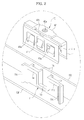
- the supporting ribs 11c may be in contact with the panel assembly 30 to support the side surface of panel assembly 30. Accordingly, once the fastening member 40 is engaged with the fastening guide 11 as illustrated in FIG. 4 , the first holders 41a provided at one side of the fastening member 40 undergo elastic deformation to slide over the holding protrusions 11a and then, undergo elastic restoration as soon as they slide over the holding protrusions 11a.
- the first holders 41a are caught by, i.e., engage, the holding protrusions 11a, preventing the fastening member 40 from being separated from the fastening guide 11.
- the supporters 41b provided at the other side of the fastening member 40 undergo elastic deformation as the fastening member 40 is engaged with the fastening guide 11, thus being elastically abutting the other side surface of the fastening guide 11 and consequently, keeping the first holders 41a engaged by the holding protrusions 11a.
- the supporters 41b urge against the fastening guide 11 to push the first holders 41a against the fastening guide 11 and to prevent the first member 41 from shifting so that the first holders 41a disengage from or slide over the protrusions 11a.
- both the first holders 41a and the supporters 41b urge against the fastening guide 11 in opposing directions so that that fastening guide 11 is stably engaged with the first member 41.
- the panel assembly 30 is placed inside the first case 10.
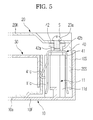
- the fastening member 40 engages with the fastening guide 11 (the plurality of fastening guides being disposed around the opening 10a), as illustrated in FIG. 5
- the second holder 41c provided at the fastening member 40 is first elastically deformed toward the indentation 11b and then, is elastically restored so as to be caught by, i.e., engages, the holding recess 30a formed in the side surface of the panel assembly 30.
- the panel assembly 30 is fastened to the first case 10 through the engagement of a number of second holders of a number of first members disposed about the opening 10a.
- the second case 20 is coupled to the first case 10 such that the second side surface 20S of the second case 20 is inserted between the other side of the fastening member 40 and the first side surface 10S of the first case 10.
- the fastening member 40 may be affixed to the second case 20.
- the fastening member 40 may be integrally formed with the second case 20, and be made of the same material as the second case 20.
- a fastening member having a boss portion is engaged with a fastening guide integrally extending from a first case, resulting in a reduced thickness of fastening parts and stable inter-coupling of the first case and second case.
- a force acting upon inter-coupling of the first case and second case may be distributed in a longitudinal direction of the fastening guide, and this may greatly reduce the possibility of deformation of the first case during inter-coupling.
- the front surface of the first case may be less subject to deformation due to the use of screws to directly couple the front case to the second case, so that the front surface remains uniformly flat.
- the first case and the second case are snapped together, without using screws, simplifying the processing of putting the first case and the second case together.
Landscapes
- Engineering & Computer Science (AREA)
- General Engineering & Computer Science (AREA)
- Theoretical Computer Science (AREA)
- Computer Hardware Design (AREA)
- Human Computer Interaction (AREA)
- Physics & Mathematics (AREA)
- General Physics & Mathematics (AREA)
- Multimedia (AREA)
- Signal Processing (AREA)
- Devices For Indicating Variable Information By Combining Individual Elements (AREA)
- Surgical Instruments (AREA)
Applications Claiming Priority (1)
| Application Number | Priority Date | Filing Date | Title |
|---|---|---|---|
| KR1020090117930A KR20110061319A (ko) | 2009-12-01 | 2009-12-01 | 디스플레이 장치 |
Publications (2)
| Publication Number | Publication Date |
|---|---|
| EP2330457A2 true EP2330457A2 (fr) | 2011-06-08 |
| EP2330457A3 EP2330457A3 (fr) | 2017-04-26 |
Family
ID=43757548
Family Applications (1)
| Application Number | Title | Priority Date | Filing Date |
|---|---|---|---|
| EP10192144.3A Withdrawn EP2330457A3 (fr) | 2009-12-01 | 2010-11-23 | Appareil d'affichage |
Country Status (4)
| Country | Link |
|---|---|
| US (1) | US8434251B2 (fr) |
| EP (1) | EP2330457A3 (fr) |
| KR (1) | KR20110061319A (fr) |
| CN (1) | CN102081883B (fr) |
Cited By (3)
| Publication number | Priority date | Publication date | Assignee | Title |
|---|---|---|---|---|
| CN103000087A (zh) * | 2011-09-15 | 2013-03-27 | 纬创资通股份有限公司 | 显示装置与其用来固定显示面板的固定结构 |
| EP2587904A1 (fr) * | 2011-10-26 | 2013-05-01 | Funai Electric Co., Ltd. | Dispositif d'affichage et télévision |
| CN103810942A (zh) * | 2012-11-09 | 2014-05-21 | 三星电子株式会社 | 弯曲的显示设备 |
Families Citing this family (20)
| Publication number | Priority date | Publication date | Assignee | Title |
|---|---|---|---|---|
| WO2011105293A1 (fr) * | 2010-02-26 | 2011-09-01 | 三洋電機株式会社 | Dispositif d'affichage d'image |
| US8760945B2 (en) | 2011-03-28 | 2014-06-24 | Samsung Electronics Co., Ltd. | Memory devices, systems and methods employing command/address calibration |
| TW201315227A (zh) * | 2011-09-21 | 2013-04-01 | Wistron Corp | 組裝結構及其相關顯示裝置 |
| TWI528133B (zh) * | 2012-02-13 | 2016-04-01 | 達運精密工業股份有限公司 | 具外框卡合設計之顯示裝置 |
| USD841096S1 (en) | 2012-04-03 | 2019-02-19 | Signcomp, Llc | Trim strip for channel signage |
| ES2687229T3 (es) | 2012-04-03 | 2018-10-24 | Signcomp, Llc | Letra de canal |
| CN103379769A (zh) * | 2012-04-25 | 2013-10-30 | 鸿富锦精密工业(深圳)有限公司 | 平板组件及使用该平板组件的电子装置 |
| US9195270B2 (en) * | 2012-05-25 | 2015-11-24 | Wistron Corporation | Display device for notebook computer |
| TWI520669B (zh) * | 2012-05-25 | 2016-02-01 | 緯創資通股份有限公司 | 筆記型電腦的螢幕 |
| CN102737549A (zh) * | 2012-06-29 | 2012-10-17 | 四川虹欧显示器件有限公司 | 一种等离子显示模组 |
| KR102013834B1 (ko) * | 2012-08-10 | 2019-08-26 | 삼성디스플레이 주식회사 | 백라이트 장치 및 이를 포함하는 표시 장치 |
| JP2014048609A (ja) * | 2012-09-04 | 2014-03-17 | Sony Corp | 固定部材及び表示装置 |
| USD882689S1 (en) | 2013-02-05 | 2020-04-28 | Signcomp, Llc | Trim strip for channel signage |
| CN104122938B (zh) * | 2013-04-23 | 2019-05-24 | 神讯电脑(昆山)有限公司 | 门扣结构 |
| US9653007B2 (en) | 2015-04-24 | 2017-05-16 | Clyde H. Boyer | Channel letter and trim cap retaining clip therefor |
| US12181920B2 (en) * | 2019-09-26 | 2024-12-31 | K-Tronics (Suzhou) Technology Co., Ltd. | Backplane, frame structure and display device |
| CN110534019B (zh) * | 2019-09-26 | 2024-04-16 | 高创(苏州)电子有限公司 | 一种背板、框架结构及显示装置 |
| KR102733835B1 (ko) * | 2019-12-31 | 2024-11-26 | 삼성전자주식회사 | 디스플레이 장치 |
| US11907016B2 (en) * | 2021-03-12 | 2024-02-20 | Apple Inc. | Electronic device |
| WO2023224172A1 (fr) * | 2022-05-20 | 2023-11-23 | 엘지전자 주식회사 | Dispositif d'affichage |
Family Cites Families (33)
| Publication number | Priority date | Publication date | Assignee | Title |
|---|---|---|---|---|
| US5452184A (en) | 1994-02-22 | 1995-09-19 | Dell Usa, L.P. | Multi-position PC board fastener with grounding element |
| US5568357A (en) * | 1994-06-15 | 1996-10-22 | Metanetics Corporation | Display support having cradled damping caps for floating core shock absorption |
| JP3034637U (ja) * | 1995-06-19 | 1997-02-25 | ディジタル イクイプメント コーポレイション | コンピュータハウジングを接合するための自己ロック二重移動式のロック装置 |
| TW353263B (en) * | 1996-11-21 | 1999-02-21 | Koninkl Philips Electronics Nv | Detachable connection between two housing sections |
| KR100218581B1 (ko) * | 1997-04-08 | 1999-09-01 | 구자홍 | 액정표시장치를 가지는 휴대용 컴퓨터 |
| US6002582A (en) * | 1998-01-05 | 1999-12-14 | Dell U.S.A., L.P. | Adapter for various LCD sizes in a computer |
| US6212366B1 (en) * | 1998-03-02 | 2001-04-03 | Motorola, Inc. | Housing assembly for a selective call receiver |
| US6501641B1 (en) * | 1998-10-23 | 2002-12-31 | Lg. Philips Lcd Co. Ltd. | Portable computer having a flat panel display device |
| JP2000236377A (ja) * | 1999-02-12 | 2000-08-29 | Matsushita Electric Ind Co Ltd | 携帯端末装置 |
| JP4142198B2 (ja) * | 1999-04-09 | 2008-08-27 | 株式会社東海理化電機製作所 | ウエビング巻取装置のカバー取付構造 |
| US6955379B1 (en) * | 2001-02-23 | 2005-10-18 | Palm, Inc. | Torsional multi-axis constraining latching system |
| US7120971B2 (en) * | 2001-03-02 | 2006-10-17 | Newfrey Llc | Low insertion effort u-base retainer |
| KR100407994B1 (ko) * | 2001-06-11 | 2003-12-03 | 엘지.필립스 엘시디 주식회사 | 평판형 디스플레이 모듈 - 하우징 어셈블리 |
| TWI298831B (en) * | 2001-07-10 | 2008-07-11 | Fujitsu Ltd | Plane unit structure, portable computer and display unit(1) |
| JP2003167235A (ja) * | 2001-12-03 | 2003-06-13 | Nec Kagoshima Ltd | 液晶表示装置の組み立て構造及びその組み立て方法 |
| US7002792B2 (en) * | 2002-04-04 | 2006-02-21 | Lg Electronics Inc. | Structure for mounting flat display module and method thereof |
| JP2004045778A (ja) * | 2002-07-12 | 2004-02-12 | Fujitsu General Ltd | 光学フィルタ取付構造 |
| KR100487435B1 (ko) * | 2002-12-24 | 2005-05-03 | 엘지.필립스 엘시디 주식회사 | 마운팅 프레임 결합구조를 갖는 액정표시장치 모듈 |
| TWI357523B (en) * | 2003-03-10 | 2012-02-01 | Samsung Electronics Co Ltd | Backlight assembly, liquid crystal display apparat |
| KR100749471B1 (ko) * | 2004-12-08 | 2007-08-14 | 삼성에스디아이 주식회사 | 플라즈마 디스플레이 장치 |
| TWM280489U (en) * | 2005-07-13 | 2005-11-11 | Hannspree Inc | Auxiliary alignment apparatus for planar display monitor and planar display monitor |
| CN100443975C (zh) * | 2005-12-21 | 2008-12-17 | 群康科技(深圳)有限公司 | 液晶显示装置 |
| CN2891599Y (zh) * | 2006-01-26 | 2007-04-18 | 中强光电股份有限公司 | 平面显示器的卡合定位装置 |
| US7874775B2 (en) * | 2006-04-26 | 2011-01-25 | A. Raymond Et Cie | Fastening device |
| TWI318701B (en) * | 2006-08-18 | 2009-12-21 | Innolux Display Corp | Liquid crystal display device |
| CN101277598B (zh) * | 2007-03-27 | 2012-08-22 | 鸿富锦精密工业(深圳)有限公司 | 壳体卡固结构 |
| KR101012587B1 (ko) * | 2007-06-04 | 2011-02-01 | 엘지전자 주식회사 | 디스플레이 장치 |
| JP2009058915A (ja) * | 2007-09-04 | 2009-03-19 | Toshiba Corp | 液晶表示装置 |
| CN101528014B (zh) * | 2008-03-07 | 2012-07-18 | 北京京东方光电科技有限公司 | 液晶显示器框架 |
| CN101308265B (zh) * | 2008-06-25 | 2010-09-22 | 友达光电股份有限公司 | 显示装置及其组装方法 |
| CN101640989A (zh) * | 2008-07-31 | 2010-02-03 | 鸿富锦精密工业(深圳)有限公司 | 电子装置的壳体 |
| CN101382674B (zh) * | 2008-10-09 | 2010-06-02 | 友达光电(苏州)有限公司 | 液晶显示装置 |
| US20120014094A1 (en) * | 2010-07-14 | 2012-01-19 | Shenzhen China Star Optoelectronics Technology Co., Ltd. | Connection component and backlight module |
-
2009
- 2009-12-01 KR KR1020090117930A patent/KR20110061319A/ko not_active Withdrawn
-
2010
- 2010-11-22 US US12/951,343 patent/US8434251B2/en not_active Expired - Fee Related
- 2010-11-23 EP EP10192144.3A patent/EP2330457A3/fr not_active Withdrawn
- 2010-11-30 CN CN201010564602.1A patent/CN102081883B/zh not_active Expired - Fee Related
Non-Patent Citations (1)
| Title |
|---|
| None |
Cited By (4)
| Publication number | Priority date | Publication date | Assignee | Title |
|---|---|---|---|---|
| CN103000087A (zh) * | 2011-09-15 | 2013-03-27 | 纬创资通股份有限公司 | 显示装置与其用来固定显示面板的固定结构 |
| CN103000087B (zh) * | 2011-09-15 | 2015-02-11 | 纬创资通股份有限公司 | 显示装置与其用来固定显示面板的固定结构 |
| EP2587904A1 (fr) * | 2011-10-26 | 2013-05-01 | Funai Electric Co., Ltd. | Dispositif d'affichage et télévision |
| CN103810942A (zh) * | 2012-11-09 | 2014-05-21 | 三星电子株式会社 | 弯曲的显示设备 |
Also Published As
| Publication number | Publication date |
|---|---|
| KR20110061319A (ko) | 2011-06-09 |
| CN102081883B (zh) | 2014-10-22 |
| US20110126440A1 (en) | 2011-06-02 |
| US8434251B2 (en) | 2013-05-07 |
| EP2330457A3 (fr) | 2017-04-26 |
| CN102081883A (zh) | 2011-06-01 |
Similar Documents
| Publication | Publication Date | Title |
|---|---|---|
| EP2330457A2 (fr) | Appareil d'affichage | |
| US20110116217A1 (en) | Image display device | |
| US8897018B2 (en) | Display device and television receiver | |
| US7552516B2 (en) | Clamp | |
| KR20150017444A (ko) | 곡면 디스플레이 장치 | |
| US8672425B2 (en) | Cabinet structure assembly | |
| US20140062274A1 (en) | Fixing member and display apparatus | |
| EP1898149A1 (fr) | Support de lampe et structure de fixation de support de lampe | |
| EP2497993B1 (fr) | Ensemble de structure d'armoire | |
| EP2352055A1 (fr) | Module à cristaux liquides et dispositif d'affichage | |
| JP5505059B2 (ja) | 表示装置 | |
| EP2752706B1 (fr) | Appareil d'affichage | |
| KR20170079001A (ko) | 디스플레이 패널용 케이스 및 이를 포함하는 디스플레이 장치 | |
| US20060262392A1 (en) | Screen assembly | |
| EP2166428B1 (fr) | Support de fixation | |
| JP7469899B2 (ja) | 表示装置 | |
| JP6180184B2 (ja) | フロント筐体固定構造 | |
| KR20110080571A (ko) | 디스플레이장치 | |
| JP2013250444A (ja) | 枠体固定部材 | |
| CN223006359U (zh) | 连接件、固定结构以及显示装置 | |
| CN204879693U (zh) | 直下式背光模组及显示器 | |
| CN210627706U (zh) | 显示设备 | |
| CN213988091U (zh) | 一种显示面板的固定组件及显示装置 | |
| JPH11167108A (ja) | 液晶表示モジュール | |
| KR200346081Y1 (ko) | 디스플레이장치 |
Legal Events
| Date | Code | Title | Description |
|---|---|---|---|
| PUAI | Public reference made under article 153(3) epc to a published international application that has entered the european phase |
Free format text: ORIGINAL CODE: 0009012 |
|
| AK | Designated contracting states |
Kind code of ref document: A2 Designated state(s): AL AT BE BG CH CY CZ DE DK EE ES FI FR GB GR HR HU IE IS IT LI LT LU LV MC MK MT NL NO PL PT RO RS SE SI SK SM TR |
|
| AX | Request for extension of the european patent |
Extension state: BA ME |
|
| RAP1 | Party data changed (applicant data changed or rights of an application transferred) |
Owner name: SAMSUNG ELECTRONICS CO., LTD. |
|
| PUAL | Search report despatched |
Free format text: ORIGINAL CODE: 0009013 |
|
| AK | Designated contracting states |
Kind code of ref document: A3 Designated state(s): AL AT BE BG CH CY CZ DE DK EE ES FI FR GB GR HR HU IE IS IT LI LT LU LV MC MK MT NL NO PL PT RO RS SE SI SK SM TR |
|
| AX | Request for extension of the european patent |
Extension state: BA ME |
|
| RIC1 | Information provided on ipc code assigned before grant |
Ipc: H05K 5/02 20060101ALI20170322BHEP Ipc: G02F 1/133 20060101AFI20170322BHEP |
|
| STAA | Information on the status of an ep patent application or granted ep patent |
Free format text: STATUS: THE APPLICATION IS DEEMED TO BE WITHDRAWN |
|
| 18D | Application deemed to be withdrawn |
Effective date: 20171027 |