EP2330559A1 - Dispositif de tomographique informatisée - Google Patents
Dispositif de tomographique informatisée Download PDFInfo
- Publication number
- EP2330559A1 EP2330559A1 EP10189045A EP10189045A EP2330559A1 EP 2330559 A1 EP2330559 A1 EP 2330559A1 EP 10189045 A EP10189045 A EP 10189045A EP 10189045 A EP10189045 A EP 10189045A EP 2330559 A1 EP2330559 A1 EP 2330559A1
- Authority
- EP
- European Patent Office
- Prior art keywords
- image
- data
- partial image
- processor
- partial
- Prior art date
- Legal status (The legal status is an assumption and is not a legal conclusion. Google has not performed a legal analysis and makes no representation as to the accuracy of the status listed.)
- Granted
Links
Images





Classifications
-
- G—PHYSICS
- G06—COMPUTING OR CALCULATING; COUNTING
- G06T—IMAGE DATA PROCESSING OR GENERATION, IN GENERAL
- G06T12/00—Tomographic reconstruction from projections
- G06T12/20—Inverse problem, i.e. transformations from projection space into object space
-
- G—PHYSICS
- G06—COMPUTING OR CALCULATING; COUNTING
- G06T—IMAGE DATA PROCESSING OR GENERATION, IN GENERAL
- G06T2211/00—Image generation
- G06T2211/40—Computed tomography
- G06T2211/432—Truncation
Definitions
- Embodiments described herein relate generally to a computed tomographic device.
- CT computed tomography
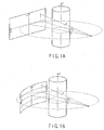
- the flat detector has a flat surface parallel to the z-axis.
- the curved detector has a cylindrical surface which is parallel to the z-axis (rotation axis) and has a focal point on an x-ray source.
- R the radius of an orbit of the x-ray source
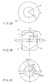
- FIGS. 2A and 2B a reconstruction volume for FS will be described.
- An FOV 20 is scanned with x-rays at source to center distance R.
- a reconstruction pixel 21 is positioned at a distance r from the center of the FOV 20.
- the z-direction of a volume reconstruction region with circular orbit scanning is limited by a divergent x-ray beam.
- the divergent x-ray beam cannot cover the full z-extent of the FOV 20 on the x-ray source side.
- Some corner regions of the FOV are not exposed to the x-rays at a particular view angle (see FIG. 2B ).
- Coverage in the z-direction is maximum at the center on the z-axis, and reduces at the periphery of the z-axis.
- a reconstruction FOV has a hexagonal shape represented by a region 22 with the thick lines in FIG. 2B . Since, however, the x-ray source rotates, missing parts are covered by the x-ray beam when the x-ray source is on the opposite side.
- H W.
- the z-coverage Moving away from the center, the z-coverage linearly reduces.
- the z-coverage is independent of the detector type, i.e., a flat or curved detector.
- a reconstruction pixel has polar coordinates (y, ⁇ ). Its short-scan reconstruction range is denoted by [ ⁇ start , ⁇ end ], as shown in FIG. 2C .
- FIG. 2E shows the volume z-coverage as a function of r.
- FIG. 2E shows z-coverage 23 for full scan, z-coverage 24 for short scan with a flat detector, and z-coverage 25 for short scan with a curved detector.
- W 80 mm
- R 600 mm.
- Short scan provides better z-coverage as compared with full scan.
- a curved detector provides z-coverage better than that of a flat detector.
- a computed tomographic device includes an x-ray source, an x-ray detector, and a processor.
- the x-ray source emits x-rays.
- the x-ray detector detects x-rays emitted by the x-ray source and transmitted through a subject.
- the processor generates an entire image for the subject based on data collected by the x-ray detector. More specifically, the processor reconstructs the first partial image of the entire image using full-scan data.
- the processor reconstructs the second partial image of the entire image using short-scan data.
- the processor reconstructs the third partial image of the entire image using data extrapolated from the full-scan data.
- the processor generates a composite image of the second and third partial images.
- the composite image has an overlapping portion of the second and third partial images. The overlapping portion is associated with the weighted sum of the second and third partial images.
- the processor generates the entire image using the first, second, and third partial images, and the composite image.
- a subject is scanned in a circular orbit for a plurality of scans to obtain circular orbit image data for the subject.
- a field-of-view (FOV) size in the z-direction is determined by the projection of the detector on the central axis.
- the z-direction of a volume reconstruction region with circular orbit scanning is limited by a divergent x-ray beam.
- the divergent x-ray beam cannot cover the full z-extent of the FOV on the x-ray source side. Consequently, some corner regions of the FOV are not exposed to the x-rays at a particular view angle.
- z-coverage is maximum at the center, and reduces at the periphery.
- FIGS. 2A and 2B show a hexagonally-shaped reconstruction FOV 22 of an FOV 20 and corner regions 26.
- the corner regions are covered by the x-ray beam when the x-ray source is on the opposite side.
- FIG. 3 shows the first example of the embodiment.
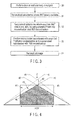
- a subject is scanned with circular orbit scanning in step 30.
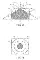
- FIG. 4 shows the geometry of the scan.
- FIG. 4 shows one half of a scanned region (FOV 45), with a fan angle indicated by lines 40.
- FOV 45 scanned region
- dashed lines 41 define a region where data can be extrapolated from an extended segment 42 located in the z-direction. The region defined by the dashed lines 41 can be reconstructed.
- Data are extrapolated by a known method. Extrapolating more data introduces more errors. When less data are used in extrapolation, there can be a jump in pixel values, thereby producing discontinuity in an image.
- PBS Picture-Based Sector
- the corner regions include regions 43 and 44.
- the PBS reconstruction is used in the regions 43 and 44. Extrapolated data is reconstructed in the region 43.
- each image pixel has a unique short-scan (SS) reconstruction view angle range.
- SS short-scan
- a plurality of pixels on a ray share the same short-scan reconstruction view angle range.
- the short-scan weighting function is computed for the image pixels.
- Such sector assignment allows the best possible data utilization, and then improves image quality.
- Subvolumes for the region are reconstructed with full-scan reconstruction based on the full-scan data (step 31).
- data for 360° are not available. In other words, for this region, data for less than 360° (short-scan data) are available.
- Subvolumes for the region are reconstructed with at least one of expanded full-scan reconstruction and PBS reconstruction based on the short-scan data (step 32).
- the region in the FOV from the line 46 up to the top of the FOV will be referred to as a short-scan region hereinafter.
- the expanded full scan and the PBS reconstruction overlap.
- the region 43 will be referred to as an extended region hereinafter.
- the expanded full-scan reconstruction indicates full-scan reconstruction based on extrapolated data.
- Subvolumes for the extended region 43 are reconstructed using the full-scan reconstruction based on the extrapolated data.
- subvolumes for the extended region 43 are reconstructed using the PBS reconstruction based on the short-scan data.
- Subvolumes for the region 44 are reconstructed using the PBS reconstruction based on the short-scan data.
- the region 44 will be referred to as a PBS region hereinafter.
- the weighted sum of the subvolumes reconstructed using the expanded full-scan reconstruction and those reconstructed using the PBS reconstruction is obtained using a weighting function (to be described later in more detail) (step 33).
- a weighting function to be described later in more detail
- subvolumes based on the weighted sum of the subvolumes reconstructed using the expanded full-scan reconstruction and those reconstructed using the PBS reconstruction are generated.
- the subvolumes reconstructed using the expanded full-scan reconstruction and those reconstructed using the PBS reconstruction are feathered.
- An image for the entire FOV is reconstructed based on the various subvolumes and the weighted sum (step 34). More specifically, an image for the entire FOV is reconstructed based on the subvolumes reconstructed in step 31, those reconstructed in step 32, and those reconstructed in step 33.
- FIGS. 5A and 5B show reconstruction regions for a slice 50 on the FOV.
- the slice 50 has a circular cross-section intersecting with the full-scan (crosshatched) region, the extended region 43, and the PBS region 44.
- the method according to the embodiment is usable for an FOV having any shape. The following description will be given by exemplifying half scanning as short scanning.
- ⁇ FS x ⁇ y ⁇ z
- H FS (r) is given by equation (1).
- ⁇ FS represents a subset of ⁇ HS .
- the full-scan algorithm given below may be used as described in A. A. Zamyatin, K. Taguchi, and M. D. Silver, "Practical Hybrid Convolution Algorithm for Helical CT Reconstruction", IEEE Transactions on Nuclear Sciences, vol. 53, no.
- f x ⁇ 1 4 ⁇ ⁇ ⁇ 0 2 ⁇ ⁇ 1 L ⁇ ⁇ x ⁇ ⁇ Q 0 g ⁇ ⁇ ⁇ ⁇ ⁇ ⁇
- Q 0 [ ⁇ ] represents DC-adjusted ramp convolution as described by Zamyatin et al.
- L( ⁇ , x') is the distance between the x-ray source y( ⁇ ) and the pixel x'. Note that full scan Feldkamp reconstruction may be used.
- a short-scan algorithm described by Zamyatin et al. is used.
- f x ⁇ 1 2 ⁇ ⁇ ⁇ ⁇ start x ⁇ ⁇ end x ⁇ w N ⁇ ⁇ x ⁇ L ⁇ ⁇ x ⁇ ⁇ K g ⁇ ⁇ ⁇ ⁇ ⁇ ⁇
- K[ ⁇ ] denotes hybrid convolution described by Zamyatin et al.
- w N denotes a weighting function. The weighting function w N will be described later in more detail.
- equations (3) above define a 1 ⁇ view angle range, i.e., a minimum view angle range. These equations are useful to find a region where short-scan reconstruction without extrapolation is possible. However, a larger short-scan range (a less than 2 ⁇ view angle range) may be used. Including more data into reconstruction reduces noise and cone beam artifacts. Thus, a maximum short-scan range as a function of the image slice z-position and r is derived.
- FIG. 2E shows volume coverage for different values of r.
- a 2 ⁇ view angle range is available for a line 23, while a 1 ⁇ view angle range is available for lines 24 (a straight detector) and 25 (a curved detector). The available view angle range varies from 1 ⁇ to 2 ⁇ between the lines 23 and 24 or between the lines 23 and 25.
- a reconstruction view angle range [ ⁇ start , ⁇ end ] is determined by a value d, as shown in FIGS. 6A and 6B .
- the value d represents a shortest distance at which the x-ray source can approach a pixel (r, ⁇ ) without projecting outside of the detector.
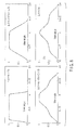
- FIG. 7A shows the view angle range as a function of r.
- the view angle range is represented in radians (rad).
- FIG. 7B shows the view angle range as a function of z.
- Each image pixel is given its own redundancy weight depending on the position of the pixel and that of the x-ray source.
- a general FDK algorithm with short-scan weighting performs weighting before convolution.
- Each pixel data is convolved and back-projected. The efficiency improves if redundancy weighting is performed after convolution, as the data needs to be convolved only once for all image pixels, and redundancy weighting is executed in back-projection.
- R. Grimmer, M. Oelhafen, U. Elstrom, and M. Kacheiriess "CT Reconstruction with Extended z-Range", Conf. Record of IEEE NSSMIC, Oct 2008 , this is achieved by rebinning data to a parallel geometry.
- an algorithm proposed in A is proposed in A.
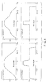
- FIG. 8 shows the central channel profiles of the weight for a plurality of view angle ranges.
- FIG. 9 shows the central channel profiles of the weight for a plurality of smoothing intervals ⁇ .
- ⁇ As ⁇ approaches 0, a short-scan weight approaches a full-scan weight. Therefore, it is desired to use a small value of ⁇ near the ends of the 2 ⁇ range. A smaller ⁇ results in noise reduction. If, however, ⁇ is too small, weighting becomes non-smooth, which may lead to streak artifacts. On the other hand, when extrapolated data is used, it is better to put a small weight on the extrapolated data at the ends of the view angle range, and therefore, it is better to use a larger value of ⁇ .
- FIG. 8 shows that the range [ ⁇ start , ⁇ end ] of the redundancy weighting function smoothly varies from full scan near the edge of an FS region to 1 ⁇ half scan for pixels near the edge of an HS region.
- ⁇ (r, z) approaches ⁇ ⁇ (r)
- ⁇ ⁇ 0.5 ⁇ ⁇ (r, z) is preferably set.
- a pre-computed weight table is preferably used.
- a weight value is preferably obtained using a look-up table.
- Extrapolated data is obtained outside the FS region, as shown in FIGS. 2 .
- the extrapolated FS data overlaps PBS data.
- w smoothly varies between 0 and 1.
- a linear function or smooth nonlinear function (for example, a polynomial 3x 2 - 2x 3 , or a trigonometric function) may be used.
- a smooth, gapless transition of w is obtained between the FS and PBS regions.
- FIG. 10 shows the second example of the embodiment.
- the second example achieves better HU uniformity and improves image quality in an extrapolated region. Additional correction is performed according to the flowchart of FIG. 10 .
- an FS image 90 and a PBS image 91 are obtained.
- the FS image 90 has a reasonably good quality CT value but contains many structural distortions.
- the PBS image 91 has a lower quality CT value but does not contain too many structural distortions.
- a difference image 92 is generated based on the FS image 90 and the PBS image 91. More specifically, a difference image 92 is generated by subtracting the FS image 90 from the PBS image 91.
- the difference image 92 has various difference values depending on the structural distortions.
- the difference image 92 is subjected to thresholding processing to generate a thresholded image 93.
- the thresholding processing uses upper and lower limit thresholds selected to exclude the structural distortions.
- the thresholded image 93 is then subjected to N-point Gaussian filtering to generate a Gaussian filtered image 94.
- the thresholded image 93 has high and low frequency components.
- An HU shift has low frequency.
- a high frequency component is removed by a Gaussian filter (low-pass filter).
- the Gaussian filtered image 94 therefore, has an HU shift at low frequency.
- the HU shift is extracted by filtering the image 94, and then added to the PBS image 91 to generate a corrected PBS image 95 having an improved HU value.
- the corrected PBS image 95 is then subjected to the above-described feathering processing to feather the extended region and the PBS region, thereby generating a final image 96 having improved image quality.
- FIG. 11 shows an x-ray computed tomographic device according to the embodiment.
- a projection data measurement system including a gantry 1 accommodates an x-ray source 3 and a two-dimensional array type x-ray detector 5.
- the x-ray source 3 generates the cone beam of an approximately cone-shaped x-ray flux.
- the two-dimensional array type x-ray detector 5 includes a plurality of detector elements arranged in a two-dimensional manner. That is, the two-dimensional array type x-ray detector 5 includes a plurality of rows, each of which includes a plurality of elements arranged in one dimension.
- the x-ray source 3 and the two-dimensional array type x-ray detector 5 are installed on a rotating ring 2 on the opposite sides of a subject.
- the subject is laid on a sliding sheet of a bed 6.
- Each detector element corresponds to one channel.
- X-rays are emitted by the x-ray source 3 toward the subject through an x-ray filter 4.
- X-rays that have transmitted through the subject are detected as an electrical signal by the two-dimensional array type x-ray detector 5.
- An x-ray controller 8 supplies a trigger signal to a high voltage generator 7.
- the high voltage generator 7 applies a high voltage to the x-ray source 3 at the timing it received the trigger signal. This causes the x-ray source 3 to emit x-rays.
- a gantry/bed controller 9 synchronously controls rotation of the rotating ring 2 of the gantry 1 and sliding of the sliding sheet of the bed 6.
- a system controller 10 functions as the control center of the entire system.
- the system controller 10 controls the x-ray controller 8 and the gantry/bed controller 9 to execute so-called helical scanning in which the x-ray source 3 moves along a helical path as seen from the subject.
- the rotating ring 2 is continuously rotated at constant angular speed while the sliding sheet is displaced at constant speed, and the x-ray source 3 emits x-rays continuously or intermittently at constant angular intervals.
- the system controller 10 may execute circular orbit scanning.
- An output signal of the two-dimensional array type x-ray detector 5 is amplified by a data collector 11 for each channel, and converted into a digital signal to generate projection data.
- the projection data output from the data collector 11 is fed to a processor 12.
- the processor 12 performs the above-described various processes using the projection data.
- the processor 12 performs interpolation, backprojection, and reconstruction on the FS region, extended region, and PBS region, as described above, and then generates an improved image for a full rectangular FOV.
- the processor 12 determines backprojection data reflecting x-ray absorption in each voxel.
- an imaging region In a helical scanning system using the cone beam of x-rays, an imaging region (FOV) has a cylindrical shape centered on the axis of rotation.
- the processor 12 defines a plurality of voxels (three-dimensional pixels) in this imaging region, and obtains the backprojection data for each voxel. Three-dimensional image data or tomographic image data compiled by using this backprojection data is supplied to a display 14.
- the display 14 visually displays the supplied three-dimensional image data as a three-dimensional image, or the supplied tomographic image data as a tomographic image.
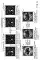
- FIG. 12 shows an example of the embodiment.
- a torso phantom was exposed to x-rays using a detector with 256 rows of detector elements with a 0.5 mm width.
- the left image in FIG. 12 is generated by conventional FDK-FS reconstruction and the right image is generated by the method according to the embodiment.
- the conventional image has strong artifacts in corner regions due to insufficient data.
- FIGS. 13, 14, and 15 show other examples.
- a 320-row detector with a 0.5 mm detector width was used.
- the left image is generated by the conventional FDK-FS processing and the right image is generated according to the embodiment.
- missing regions are masked in the conventional image and the image processed according to the embodiment has greater coverage and details.
- the images of FIGS. 14 and 15 show the hexagonal FOV of the conventional image and the rectangular FOV of the image generated by the processing according to the embodiment.
- the images according to the embodiment exhibit good CT values with no shape distortion in corner regions.
- the embodiment may also be embodied in the form of a computer-readable medium storing a program to cause a computer to carry out the above-described various operations and functions.
Landscapes
- Physics & Mathematics (AREA)
- General Physics & Mathematics (AREA)
- Engineering & Computer Science (AREA)
- Theoretical Computer Science (AREA)
- Apparatus For Radiation Diagnosis (AREA)
Applications Claiming Priority (2)
| Application Number | Priority Date | Filing Date | Title |
|---|---|---|---|
| US12/609,999 US8559687B2 (en) | 2009-10-30 | 2009-10-30 | Method for circular scan reconstruction in computed tomography and computed tomographic device |
| JP2010181858A JP5641811B2 (ja) | 2009-10-30 | 2010-08-16 | コンピュータ断層撮影装置 |
Publications (3)
| Publication Number | Publication Date |
|---|---|
| EP2330559A1 true EP2330559A1 (fr) | 2011-06-08 |
| EP2330559B1 EP2330559B1 (fr) | 2013-05-15 |
| EP2330559B9 EP2330559B9 (fr) | 2013-11-06 |
Family
ID=43447021
Family Applications (1)
| Application Number | Title | Priority Date | Filing Date |
|---|---|---|---|
| EP10189045.7A Active EP2330559B9 (fr) | 2009-10-30 | 2010-10-27 | Dispositif de tomographique informatisée |
Country Status (1)
| Country | Link |
|---|---|
| EP (1) | EP2330559B9 (fr) |
Cited By (1)
| Publication number | Priority date | Publication date | Assignee | Title |
|---|---|---|---|---|
| CN114364321A (zh) * | 2019-09-12 | 2022-04-15 | 昂达博思有限公司 | 一种x射线数字断层合成系统和方法 |
Citations (4)
| Publication number | Priority date | Publication date | Assignee | Title |
|---|---|---|---|---|
| EP0428348A2 (fr) * | 1989-11-13 | 1991-05-22 | General Electric Company | Tomographie par calculateur avec balayage helicoidal |
| US6282256B1 (en) * | 1998-09-24 | 2001-08-28 | U.S. Philips Corporation | Computed tomography method utilizing a conical radiation beam |
| US20070297661A1 (en) * | 2006-05-31 | 2007-12-27 | The Board Of Trustees Of The Leland Stanford Junior University | Tomographic reconstruction for x-ray cone-beam scan data |
| WO2008064367A2 (fr) * | 2006-11-24 | 2008-05-29 | Kabushiki Kaisha Toshiba | Procédé et système pour une reconstruction tomographique en imagerie médicale à l'aide de la trajectoire circulaire et linéaire |
-
2010
- 2010-10-27 EP EP10189045.7A patent/EP2330559B9/fr active Active
Patent Citations (4)
| Publication number | Priority date | Publication date | Assignee | Title |
|---|---|---|---|---|
| EP0428348A2 (fr) * | 1989-11-13 | 1991-05-22 | General Electric Company | Tomographie par calculateur avec balayage helicoidal |
| US6282256B1 (en) * | 1998-09-24 | 2001-08-28 | U.S. Philips Corporation | Computed tomography method utilizing a conical radiation beam |
| US20070297661A1 (en) * | 2006-05-31 | 2007-12-27 | The Board Of Trustees Of The Leland Stanford Junior University | Tomographic reconstruction for x-ray cone-beam scan data |
| WO2008064367A2 (fr) * | 2006-11-24 | 2008-05-29 | Kabushiki Kaisha Toshiba | Procédé et système pour une reconstruction tomographique en imagerie médicale à l'aide de la trajectoire circulaire et linéaire |
Non-Patent Citations (5)
| Title |
|---|
| A. A. ZAMYATIN; K. TAGUCHI; M. D. SILVER: "Practical Hybrid Convolution Algorithm for Helical CT Reconstruction", IEEE TRANSACTIONS ON NUCLEAR SCIENCES, vol. 53, no. 1, pages 167 - 174 |
| NOO, M.; DEFRISE, R.; CLACKDOYLE; H. KUDO: "Image reconstruction from fan-beam projections on less than a short scan", PHYS. MED. BIOL., vol. 47, 2002, pages 2525 - 2546 |
| R. GRIMMER; M. OELHAFEN; U. ELSTROM; M. KACHEIRIESS: "CT Reconstruction with Extended z-Range", CONF. RECORD OF IEEE NSSMIC, October 2008 (2008-10-01) |
| RAINER GRIMMER ET AL: "Cone-beam CT sequence scan reconstruction with improved dose usage and scan coverage", 2009 IEEE NUCLEAR SCIENCE SYMPOSIUM AND MEDICAL IMAGING CONFERENCE (NSS/MIC 2009), IEEE, ORLANDO, FL, USA, 24 October 2009 (2009-10-24), pages 3759 - 3763, XP031621271, ISBN: 978-1-4244-3961-4 * |
| ZHYE YIN ET AL: "3D analytic cone-beam reconstruction for less than a full scan using a multi-source CT system", NUCLEAR SCIENCE SYMPOSIUM CONFERENCE RECORD, 2007. NSS '07. IEEE, IEEE, PI, 1 October 2007 (2007-10-01), pages 3929 - 3932, XP031206463, ISBN: 978-1-4244-0922-8 * |
Cited By (1)
| Publication number | Priority date | Publication date | Assignee | Title |
|---|---|---|---|---|
| CN114364321A (zh) * | 2019-09-12 | 2022-04-15 | 昂达博思有限公司 | 一种x射线数字断层合成系统和方法 |
Also Published As
| Publication number | Publication date |
|---|---|
| EP2330559B1 (fr) | 2013-05-15 |
| EP2330559B9 (fr) | 2013-11-06 |
Similar Documents
| Publication | Publication Date | Title |
|---|---|---|
| US8559687B2 (en) | Method for circular scan reconstruction in computed tomography and computed tomographic device | |
| JP3660586B2 (ja) | 非対称検出器によるハーフスキャンct復元 | |
| JP3609425B2 (ja) | 非対称検出システムを備えたらせんコンピュータ断層撮影法 | |
| JP4401751B2 (ja) | アーティファクト低減を容易にする方法及び装置 | |
| US9662084B2 (en) | Method and apparatus for iteratively reconstructing tomographic images from electrocardiographic-gated projection data | |
| US8284892B2 (en) | System and method for image reconstruction | |
| US8175218B2 (en) | Interpolation interlacing based data upsampling algorithm for cone-beam x-ray CT flying focal spot projection data | |
| EP1489559B1 (fr) | Dispositif pour la reconstruction de données à faisceau conique et dispositif de tomographie par ordinateur | |
| JP4557321B2 (ja) | 画像再構成装置 | |
| US7792238B2 (en) | Method and system for reconstructing cone-beam projection data with reduced artifacts | |
| JPWO2016017534A1 (ja) | X線撮像装置および画像再構成方法 | |
| JP5133690B2 (ja) | ボクセルに依存する補間を用いる画像再構成 | |
| JP4644785B2 (ja) | コーンビームct画像再構成におけるアーチファクトを低減するための方法及び装置 | |
| US6775347B2 (en) | Methods and apparatus for reconstructing an image of an object | |
| JP2000102530A (ja) | 被検体の中の関心領域の3次元コンピュ―タ断層画像形成のための方法および装置 | |
| IL116257A (en) | Helical interpolative algorithm for image reconstruction in a ct system | |
| US7027552B2 (en) | High resolution CT scanner | |
| US8494111B2 (en) | System and method for image reconstruction for helical cone beam computed tomography with factorized redundancy weighting | |
| JP4481377B2 (ja) | 画像処理装置、及び画像処理方法 | |
| US8385620B2 (en) | Method and system for multi-detector-row computed tomography utilizing projection data up-sampling with shift | |
| US8577113B2 (en) | Image reconstruction for truncated detector array | |
| EP2330559B9 (fr) | Dispositif de tomographique informatisée | |
| US6999550B2 (en) | Method and apparatus for obtaining data for reconstructing images of an object | |
| JP3950101B2 (ja) | X線コンピュータ断層撮影装置 | |
| US7734079B2 (en) | Methods and apparatus for image reconstruction |
Legal Events
| Date | Code | Title | Description |
|---|---|---|---|
| PUAI | Public reference made under article 153(3) epc to a published international application that has entered the european phase |
Free format text: ORIGINAL CODE: 0009012 |
|
| 17P | Request for examination filed |
Effective date: 20101027 |
|
| AK | Designated contracting states |
Kind code of ref document: A1 Designated state(s): AL AT BE BG CH CY CZ DE DK EE ES FI FR GB GR HR HU IE IS IT LI LT LU LV MC MK MT NL NO PL PT RO RS SE SI SK SM TR |
|
| AX | Request for extension of the european patent |
Extension state: BA ME |
|
| RAP1 | Party data changed (applicant data changed or rights of an application transferred) |
Owner name: TOSHIBA MEDICAL SYSTEMS CORPORATION Owner name: KABUSHIKI KAISHA TOSHIBA |
|
| GRAP | Despatch of communication of intention to grant a patent |
Free format text: ORIGINAL CODE: EPIDOSNIGR1 |
|
| RIC1 | Information provided on ipc code assigned before grant |
Ipc: G06T 11/00 20060101AFI20121019BHEP |
|
| GRAS | Grant fee paid |
Free format text: ORIGINAL CODE: EPIDOSNIGR3 |
|
| GRAA | (expected) grant |
Free format text: ORIGINAL CODE: 0009210 |
|
| AK | Designated contracting states |
Kind code of ref document: B1 Designated state(s): AL AT BE BG CH CY CZ DE DK EE ES FI FR GB GR HR HU IE IS IT LI LT LU LV MC MK MT NL NO PL PT RO RS SE SI SK SM TR |
|
| REG | Reference to a national code |
Ref country code: GB Ref legal event code: FG4D Ref country code: CH Ref legal event code: EP |
|
| REG | Reference to a national code |
Ref country code: AT Ref legal event code: REF Ref document number: 612482 Country of ref document: AT Kind code of ref document: T Effective date: 20130615 |
|
| REG | Reference to a national code |
Ref country code: IE Ref legal event code: FG4D |
|
| REG | Reference to a national code |
Ref country code: DE Ref legal event code: R096 Ref document number: 602010007068 Country of ref document: DE Effective date: 20130711 |
|
| RAP2 | Party data changed (patent owner data changed or rights of a patent transferred) |
Owner name: TOSHIBA MEDICAL SYSTEMS CORPORATION Owner name: KABUSHIKI KAISHA TOSHIBA |
|
| RIN2 | Information on inventor provided after grant (corrected) |
Inventor name: ZOU, YU Inventor name: AKINO, NARUOMI Inventor name: LABNO, THOMAS Inventor name: ZAMYATIN, ALEKSANDR Inventor name: SILVER, MICHAEL D. Inventor name: CHIANG, BE-SHAN |
|
| REG | Reference to a national code |
Ref country code: NL Ref legal event code: T3 |
|
| REG | Reference to a national code |
Ref country code: AT Ref legal event code: MK05 Ref document number: 612482 Country of ref document: AT Kind code of ref document: T Effective date: 20130515 |
|
| REG | Reference to a national code |
Ref country code: LT Ref legal event code: MG4D |
|
| PG25 | Lapsed in a contracting state [announced via postgrant information from national office to epo] |
Ref country code: ES Free format text: LAPSE BECAUSE OF FAILURE TO SUBMIT A TRANSLATION OF THE DESCRIPTION OR TO PAY THE FEE WITHIN THE PRESCRIBED TIME-LIMIT Effective date: 20130826 Ref country code: AT Free format text: LAPSE BECAUSE OF FAILURE TO SUBMIT A TRANSLATION OF THE DESCRIPTION OR TO PAY THE FEE WITHIN THE PRESCRIBED TIME-LIMIT Effective date: 20130515 Ref country code: GR Free format text: LAPSE BECAUSE OF FAILURE TO SUBMIT A TRANSLATION OF THE DESCRIPTION OR TO PAY THE FEE WITHIN THE PRESCRIBED TIME-LIMIT Effective date: 20130816 Ref country code: NO Free format text: LAPSE BECAUSE OF FAILURE TO SUBMIT A TRANSLATION OF THE DESCRIPTION OR TO PAY THE FEE WITHIN THE PRESCRIBED TIME-LIMIT Effective date: 20130815 Ref country code: LT Free format text: LAPSE BECAUSE OF FAILURE TO SUBMIT A TRANSLATION OF THE DESCRIPTION OR TO PAY THE FEE WITHIN THE PRESCRIBED TIME-LIMIT Effective date: 20130515 Ref country code: FI Free format text: LAPSE BECAUSE OF FAILURE TO SUBMIT A TRANSLATION OF THE DESCRIPTION OR TO PAY THE FEE WITHIN THE PRESCRIBED TIME-LIMIT Effective date: 20130515 Ref country code: SE Free format text: LAPSE BECAUSE OF FAILURE TO SUBMIT A TRANSLATION OF THE DESCRIPTION OR TO PAY THE FEE WITHIN THE PRESCRIBED TIME-LIMIT Effective date: 20130515 Ref country code: IS Free format text: LAPSE BECAUSE OF FAILURE TO SUBMIT A TRANSLATION OF THE DESCRIPTION OR TO PAY THE FEE WITHIN THE PRESCRIBED TIME-LIMIT Effective date: 20130915 Ref country code: SI Free format text: LAPSE BECAUSE OF FAILURE TO SUBMIT A TRANSLATION OF THE DESCRIPTION OR TO PAY THE FEE WITHIN THE PRESCRIBED TIME-LIMIT Effective date: 20130515 Ref country code: PT Free format text: LAPSE BECAUSE OF FAILURE TO SUBMIT A TRANSLATION OF THE DESCRIPTION OR TO PAY THE FEE WITHIN THE PRESCRIBED TIME-LIMIT Effective date: 20130916 |
|
| PG25 | Lapsed in a contracting state [announced via postgrant information from national office to epo] |
Ref country code: HR Free format text: LAPSE BECAUSE OF FAILURE TO SUBMIT A TRANSLATION OF THE DESCRIPTION OR TO PAY THE FEE WITHIN THE PRESCRIBED TIME-LIMIT Effective date: 20130515 Ref country code: PL Free format text: LAPSE BECAUSE OF FAILURE TO SUBMIT A TRANSLATION OF THE DESCRIPTION OR TO PAY THE FEE WITHIN THE PRESCRIBED TIME-LIMIT Effective date: 20130515 Ref country code: RS Free format text: LAPSE BECAUSE OF FAILURE TO SUBMIT A TRANSLATION OF THE DESCRIPTION OR TO PAY THE FEE WITHIN THE PRESCRIBED TIME-LIMIT Effective date: 20130515 Ref country code: BG Free format text: LAPSE BECAUSE OF FAILURE TO SUBMIT A TRANSLATION OF THE DESCRIPTION OR TO PAY THE FEE WITHIN THE PRESCRIBED TIME-LIMIT Effective date: 20130815 |
|
| PG25 | Lapsed in a contracting state [announced via postgrant information from national office to epo] |
Ref country code: LV Free format text: LAPSE BECAUSE OF FAILURE TO SUBMIT A TRANSLATION OF THE DESCRIPTION OR TO PAY THE FEE WITHIN THE PRESCRIBED TIME-LIMIT Effective date: 20130515 |
|
| PG25 | Lapsed in a contracting state [announced via postgrant information from national office to epo] |
Ref country code: SK Free format text: LAPSE BECAUSE OF FAILURE TO SUBMIT A TRANSLATION OF THE DESCRIPTION OR TO PAY THE FEE WITHIN THE PRESCRIBED TIME-LIMIT Effective date: 20130515 Ref country code: EE Free format text: LAPSE BECAUSE OF FAILURE TO SUBMIT A TRANSLATION OF THE DESCRIPTION OR TO PAY THE FEE WITHIN THE PRESCRIBED TIME-LIMIT Effective date: 20130515 Ref country code: DK Free format text: LAPSE BECAUSE OF FAILURE TO SUBMIT A TRANSLATION OF THE DESCRIPTION OR TO PAY THE FEE WITHIN THE PRESCRIBED TIME-LIMIT Effective date: 20130515 Ref country code: CZ Free format text: LAPSE BECAUSE OF FAILURE TO SUBMIT A TRANSLATION OF THE DESCRIPTION OR TO PAY THE FEE WITHIN THE PRESCRIBED TIME-LIMIT Effective date: 20130515 Ref country code: BE Free format text: LAPSE BECAUSE OF FAILURE TO SUBMIT A TRANSLATION OF THE DESCRIPTION OR TO PAY THE FEE WITHIN THE PRESCRIBED TIME-LIMIT Effective date: 20130515 |
|
| PG25 | Lapsed in a contracting state [announced via postgrant information from national office to epo] |
Ref country code: RO Free format text: LAPSE BECAUSE OF FAILURE TO SUBMIT A TRANSLATION OF THE DESCRIPTION OR TO PAY THE FEE WITHIN THE PRESCRIBED TIME-LIMIT Effective date: 20130515 Ref country code: IT Free format text: LAPSE BECAUSE OF FAILURE TO SUBMIT A TRANSLATION OF THE DESCRIPTION OR TO PAY THE FEE WITHIN THE PRESCRIBED TIME-LIMIT Effective date: 20130515 |
|
| PLBE | No opposition filed within time limit |
Free format text: ORIGINAL CODE: 0009261 |
|
| STAA | Information on the status of an ep patent application or granted ep patent |
Free format text: STATUS: NO OPPOSITION FILED WITHIN TIME LIMIT |
|
| 26N | No opposition filed |
Effective date: 20140218 |
|
| REG | Reference to a national code |
Ref country code: DE Ref legal event code: R097 Ref document number: 602010007068 Country of ref document: DE Effective date: 20140218 |
|
| PG25 | Lapsed in a contracting state [announced via postgrant information from national office to epo] |
Ref country code: MC Free format text: LAPSE BECAUSE OF FAILURE TO SUBMIT A TRANSLATION OF THE DESCRIPTION OR TO PAY THE FEE WITHIN THE PRESCRIBED TIME-LIMIT Effective date: 20130515 |
|
| REG | Reference to a national code |
Ref country code: IE Ref legal event code: MM4A |
|
| REG | Reference to a national code |
Ref country code: FR Ref legal event code: ST Effective date: 20140630 |
|
| PG25 | Lapsed in a contracting state [announced via postgrant information from national office to epo] |
Ref country code: FR Free format text: LAPSE BECAUSE OF NON-PAYMENT OF DUE FEES Effective date: 20131031 |
|
| PG25 | Lapsed in a contracting state [announced via postgrant information from national office to epo] |
Ref country code: IE Free format text: LAPSE BECAUSE OF NON-PAYMENT OF DUE FEES Effective date: 20131027 |
|
| PG25 | Lapsed in a contracting state [announced via postgrant information from national office to epo] |
Ref country code: SM Free format text: LAPSE BECAUSE OF FAILURE TO SUBMIT A TRANSLATION OF THE DESCRIPTION OR TO PAY THE FEE WITHIN THE PRESCRIBED TIME-LIMIT Effective date: 20130515 |
|
| REG | Reference to a national code |
Ref country code: CH Ref legal event code: PL |
|
| GBPC | Gb: european patent ceased through non-payment of renewal fee |
Effective date: 20141027 |
|
| PG25 | Lapsed in a contracting state [announced via postgrant information from national office to epo] |
Ref country code: TR Free format text: LAPSE BECAUSE OF FAILURE TO SUBMIT A TRANSLATION OF THE DESCRIPTION OR TO PAY THE FEE WITHIN THE PRESCRIBED TIME-LIMIT Effective date: 20130515 Ref country code: CY Free format text: LAPSE BECAUSE OF FAILURE TO SUBMIT A TRANSLATION OF THE DESCRIPTION OR TO PAY THE FEE WITHIN THE PRESCRIBED TIME-LIMIT Effective date: 20130515 |
|
| PG25 | Lapsed in a contracting state [announced via postgrant information from national office to epo] |
Ref country code: CH Free format text: LAPSE BECAUSE OF NON-PAYMENT OF DUE FEES Effective date: 20141031 Ref country code: MK Free format text: LAPSE BECAUSE OF FAILURE TO SUBMIT A TRANSLATION OF THE DESCRIPTION OR TO PAY THE FEE WITHIN THE PRESCRIBED TIME-LIMIT Effective date: 20130515 Ref country code: HU Free format text: LAPSE BECAUSE OF FAILURE TO SUBMIT A TRANSLATION OF THE DESCRIPTION OR TO PAY THE FEE WITHIN THE PRESCRIBED TIME-LIMIT; INVALID AB INITIO Effective date: 20101027 Ref country code: GB Free format text: LAPSE BECAUSE OF NON-PAYMENT OF DUE FEES Effective date: 20141027 Ref country code: LI Free format text: LAPSE BECAUSE OF NON-PAYMENT OF DUE FEES Effective date: 20141031 Ref country code: LU Free format text: LAPSE BECAUSE OF NON-PAYMENT OF DUE FEES Effective date: 20131027 |
|
| PG25 | Lapsed in a contracting state [announced via postgrant information from national office to epo] |
Ref country code: MT Free format text: LAPSE BECAUSE OF FAILURE TO SUBMIT A TRANSLATION OF THE DESCRIPTION OR TO PAY THE FEE WITHIN THE PRESCRIBED TIME-LIMIT Effective date: 20130515 |
|
| REG | Reference to a national code |
Ref country code: NL Ref legal event code: PD Owner name: TOSHIBA MEDICAL SYSTEMS CORPORATION; JP Free format text: DETAILS ASSIGNMENT: VERANDERING VAN EIGENAAR(S), OVERDRACHT; FORMER OWNER NAME: TOSHIBA MEDICAL SYSTEMS CORPORATION Effective date: 20160627 |
|
| REG | Reference to a national code |
Ref country code: DE Ref legal event code: R081 Ref document number: 602010007068 Country of ref document: DE Owner name: TOSHIBA MEDICAL SYSTEMS CORPORATION, OTAWARA-S, JP Free format text: FORMER OWNERS: KABUSHIKI KAISHA TOSHIBA, TOKIO/TOKYO, JP; TOSHIBA MEDICAL SYSTEMS CORPORATION, OTAWARA-SHI, TOCHIGI-KEN, JP Ref country code: DE Ref legal event code: R082 Ref document number: 602010007068 Country of ref document: DE Representative=s name: KRAMER BARSKE SCHMIDTCHEN PATENTANWAELTE PARTG, DE |
|
| PG25 | Lapsed in a contracting state [announced via postgrant information from national office to epo] |
Ref country code: AL Free format text: LAPSE BECAUSE OF FAILURE TO SUBMIT A TRANSLATION OF THE DESCRIPTION OR TO PAY THE FEE WITHIN THE PRESCRIBED TIME-LIMIT Effective date: 20130515 |
|
| PGFP | Annual fee paid to national office [announced via postgrant information from national office to epo] |
Ref country code: NL Payment date: 20250912 Year of fee payment: 16 |
|
| PGFP | Annual fee paid to national office [announced via postgrant information from national office to epo] |
Ref country code: DE Payment date: 20250902 Year of fee payment: 16 |