EP2330681A1 - Kompakte OMT-Vorrichtung - Google Patents
Kompakte OMT-Vorrichtung Download PDFInfo
- Publication number
- EP2330681A1 EP2330681A1 EP09178229A EP09178229A EP2330681A1 EP 2330681 A1 EP2330681 A1 EP 2330681A1 EP 09178229 A EP09178229 A EP 09178229A EP 09178229 A EP09178229 A EP 09178229A EP 2330681 A1 EP2330681 A1 EP 2330681A1
- Authority
- EP
- European Patent Office
- Prior art keywords
- septum
- waveguide
- section
- omt
- degrees
- Prior art date
- Legal status (The legal status is an assumption and is not a legal conclusion. Google has not performed a legal analysis and makes no representation as to the accuracy of the status listed.)
- Ceased
Links
Images



Classifications
-
- H—ELECTRICITY
- H01—ELECTRIC ELEMENTS
- H01P—WAVEGUIDES; RESONATORS, LINES, OR OTHER DEVICES OF THE WAVEGUIDE TYPE
- H01P1/00—Auxiliary devices
- H01P1/16—Auxiliary devices for mode selection, e.g. mode suppression or mode promotion; for mode conversion
- H01P1/161—Auxiliary devices for mode selection, e.g. mode suppression or mode promotion; for mode conversion sustaining two independent orthogonal modes, e.g. orthomode transducer
-
- H—ELECTRICITY
- H01—ELECTRIC ELEMENTS
- H01P—WAVEGUIDES; RESONATORS, LINES, OR OTHER DEVICES OF THE WAVEGUIDE TYPE
- H01P1/00—Auxiliary devices
- H01P1/165—Auxiliary devices for rotating the plane of polarisation
-
- H—ELECTRICITY
- H01—ELECTRIC ELEMENTS
- H01P—WAVEGUIDES; RESONATORS, LINES, OR OTHER DEVICES OF THE WAVEGUIDE TYPE
- H01P1/00—Auxiliary devices
- H01P1/20—Frequency-selective devices, e.g. filters
- H01P1/213—Frequency-selective devices, e.g. filters combining or separating two or more different frequencies
- H01P1/2131—Frequency-selective devices, e.g. filters combining or separating two or more different frequencies with combining or separating polarisations
-
- H—ELECTRICITY
- H01—ELECTRIC ELEMENTS
- H01Q—ANTENNAS, i.e. RADIO AERIALS
- H01Q15/00—Devices for reflection, refraction, diffraction or polarisation of waves radiated from an antenna, e.g. quasi-optical devices
- H01Q15/24—Polarising devices; Polarisation filters
- H01Q15/242—Polarisation converters
- H01Q15/246—Polarisation converters rotating the plane of polarisation of a linear polarised wave
Definitions
- the present invention relates to a waveguide apparatus for electro-magnetic signal processing and more especially to an apparatus capable of dividing an orthogonally polarized electro-magnetic signal into two linearly polarized signals and, in reverse direction, capable of combining two linearly polarized signals into an orthogonally polarized electro-magnetic signal.
- the modern antennas on board of satellites are frequently implemented by an active/ passive array of feeds in the focal plane of a reflector system when using orthogonally polarized signals in the feed systems.
- the cluster of feeds is arranged closely side by side causing implementation problems due to their often complex shape, especially when a great number of feeds are used in a compact configuration. Therefore, the feed waveguide configurations become very intricate and it is important to reduce the size of the feeds in the X and Y axes (with Z being the propagation axis). If the radiating element of the feed is small, the limiting factor that prevents the size reduction is the orthomode transducer (OMT).
- OMT orthomode transducer
- the OMT is a waveguide-component capable of dividing an orthogonally polarized electro-magnetic signal into two linearly polarized signals and, in reverse direction, capable of combining two linearly polarized signals into an orthogonally polarized electro-magnetic signal. It is therefore desirable for OMTs used in feed systems comprising a plurality of closely located signal sources to be compact and to have minimum complexity.
- OMT devices Several types are known in the art. Complex OMTs such as coaxial OMTs, Boifot OMTs, ortho-mode junctions or turnstile junctions offer good bandwidth and/or power handling.
- feed systems using the above types of OMT devices face assembling problems, e.g., due to the need for complicated waveguide networks to recombine all the ports, especially when a great number of signal sources have to be fed and when the sources are close to each other.
- a further type of an OMT is disclosed in FR 2904478 A1 and by Chattopadhyay et al. in Microwave and Guided Wave Letters, IEEE, Vol 8, Issue 12, Dec. 1998, pages 421-423 .
- This type of OMT apparatus is more compact than the complex OMTs but requires a coupling area with a slot iris of small dimensions that reduces drastically the power handling of the device.
- an orthomode transducer (OMT) device with a rectangular or circular guide section, said guide section having a constant cross-section perpendicular to a lengthwise direction of said guide section and first and second lengthwise opposed open ends.
- An orthomode transducer in the context of this invention is capable of splitting a linear orthogonally polarized electromagnetic signal into a plurality of linearly polarized frequency components and vice versa.
- a linear orthogonally polarized electromagnetic signal in the context of this invention comprises two electromagnetic signals with linear polarization orthogonally polarized with respect to each other.
- the polarization axes of the linearly polarized signals are orthogonal to each other.
- Signals with a linear polarization comprise a polarization vector wherein the tip of the vector traces out a single line in the plane, in contrast to signals with a circular polarization.
- Splitting in the context of this invention means that the OMT separates a linear orthogonally polarized electromagnetic signal entering the OMT in waveguide portion into two linearly polarized signals that are each comprised in separate waveguide portions (receive path).
- an OMT is a passive component, it can be operated in reverse direction, i.e. to combine two linearly polarized signals from separate waveguide portions into a linear orthogonally polarized electromagnetic signal propagating in the same waveguide portion (transmit path).
- the OMT device further comprises a first waveguide portion having the same cross-section as said guide section, said first waveguide section being capable of supporting two orthogonal linear polarization modes of signal propagation, and said first waveguide section extending between said first lengthwise open end of the guide section and a septum.
- the septum of the OMT extends from an end of the first wave guide portion towards the second lengthwise open end of said guide section and divides said guide section into a second waveguide portion and a third waveguide portion having cross-sections smaller than the cross-section of said first wave-guide portion.
- the septum may be a metallic sheet or thin plate.
- the septum may also be a dielectric sheet.
- the second waveguide portion and the third waveguide portion are capable of supporting propagation of a linearly polarized signal, i.e., the linearly polarized transverse electric field signal.
- said septum is dimensioned as to induce a differential phase shift of 180 degrees or substantially 180 degrees or a multiple thereof between components of the linear polarization modes that are perpendicular to said septum and components that are parallel to said septum.
- An OMT is usually operated in a given frequency band.
- the septum is dimensioned so as to cause a differential phase shift of substantially 180 degrees for the frequencies within this frequency band.
- the phase shift in dependence of the frequency follows a curve similar to a parabola with two frequencies within this frequency band having a phase shift of exactly 180 degrees between components of the linear polarization modes that are perpendicular to said septum and components that are parallel to said septum.
- phase shift induced by the septum for the frequencies between these two frequencies may be slightly above 180 degrees, whereas the phase shift of the remaining frequencies of the frequency band may be slightly below 180 degrees.
- the phase shift induced by the septum lies within a range of +/- 2 degrees of 180 degrees.
- the phase shift induced by a septum according to the invention lies in a small range around 180 degrees for all frequencies of the frequency band that is used for the OMT.
- the OMT is used for splitting a linear orthogonally polarized electromagnetic signal into a plurality of linearly polarized frequency components or vice versa, wherein a polarization axis of a linear orthogonally polarized electromagnetic signal entering or exiting the waveguide at said first lengthwise open end may be provided at an angle of 45 degrees relative to the septum.
- the septum may therefore be provided at an angle of 45 degrees relative to the polarization axes of the linear orthogonally polarized electromagnetic signal.
- a linear orthogonally polarized electromagnetic signal entering the waveguide may be considered to have two orthogonal polarization components.
- the first of the two orthogonal polarization components enters or exits the waveguide at the first lengthwise open end at an angle of +45 degrees with respect to the plane defined by the septum; the second orthogonal polarization components at an angle of -45 degrees.
- each of the two orthogonal polarization components has a field component parallel to the septum and one perpendicular. For signals with a linear polarization, these field components are in phase.
- the length and the shape of the septum is chosen to cause a 180 degree phase shift between the field component parallel to the septum and the field component perpendicular to the septum.
- said septum of the OMT may extend with increasing height from an end of the first wave guide portion towards the second lengthwise open end of said guide section.
- the height of the septum may be successively increased.
- both field components add together on one side of the septum and cancel on the other. In other words, they are recombined either in the second or third wave guide portion depending on the incoming polarization.
- the OMT divides an orthogonally polarized electro-magnetic signal into two linearly polarized signals wherein the second and third wave guide portions which are isolated from each other at the end of the septum each comprise either the first polarization component or the second polarization component depending on the incoming polarization.
- the OMT device of the present invention has a compact configuration which embodies a waveguide able to extract or combine two orthogonal linear polarizations with a single integrated septum.
- no resonant structures such as irises or metallic slots are required to split orthogonal polarizations.
- the entire phase shift effect is caused by a single component with increasing height that causes at the same time the phase shifting effect and separates the waveguide section into the second and third waveguide section for the propagation of the splitted signals.
- the compact OMT device has a high power handling and is cost-efficient to manufacture.
- the waveguide access of the compact OMT is perfectly parallel enabling an easy and very compact assembly of multi-feed arrays in contrast to conventional OMT devices with perpendicular waveguide access.
- the septum may be positioned in the middle of two opposite elongated walls of the rectangular waveguide resulting in parallel second and third waveguide sections with the same cross-section.
- the septum may comprise at least a step-shaped portion.
- a septum with a step-shaped portion causes the field component parallel to the septum to rotate along the septum and at the same time is cost-efficient to manufacture.
- the septum may comprise at least a concave-shaped portion.
- the septum may comprise a combination of step-shaped and concave-shaped portions.
- the form of the septum as a thin metallic sheet which is successively increasing in height along the longitudinal axis of the waveguide induces the required phase shift and causes only minimal power handling losses.
- the invention is not restricted to a particular shape of a septum.
- the length, width, height of septum all influence that phase shift induced by the septum.
- the septum width may also increase over the length of the septum, e.g. the width of the septum may also comprise a step-shaped portion as long as the septum induces a substantially 180 degree phase shift.
- a circular access may be coupled to an open end of the first wave guide section.
- a feed array assembly for an antenna system comprising a plurality of OMTs of the invention.
- the guide sections of a feed array assembly of the plurality of orthomode transducers of the invention may be arranged in parallel. Since the OMTs have a parallel waveguide access and do not require perpendicular waveguide components, a high number of feeds can be assembled in a very compact configuration. In order to a achieve a highly compact configuration, the OMTs may be assembled to a feed array such that corresponding center points of the guide sections or the longitudinal wave guide axes of three adjacent orthomode transducers are equidistant.
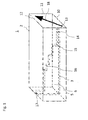
- Fig. 1 illustrates a perspective side view of a compact OMT according to an embodiment of the invention.
- the orthomode transducer 1 comprises an elongate piece of a hollow electrically conductive waveguide 2 having a square cross-section.
- the four walls of the waveguide are designated 10, 11, 12, and 13, as shown.
- a thin elongated electrically conductive septum 3 extends along the longitudinal axis of the compact OMT and forms a plane that is situated halfway between walls 11 and 13. This particular septum 3 has a step-shaped portion causing the septum 3 to be successively increasing in height between the walls 10 and 12.
- the waveguide portion between a first open end of the waveguide (indicated by the black arrow in Fig. 1 ) and the starting point 14 of the septum form the first waveguide portion 4 that has the same cross-section as the guide section 2.
- the cross-section of the first waveguide portion 4 (which is the corresponding section of the waveguide 2) is so dimensioned as to support two orthogonal polarization modes of signal propagation with horizontal and vertical electric field, respectively, e.g. the TE01 and TE10 modes.
- the septum 3 further divides the guide section 2 into a second waveguide portion 5 and a third waveguide portion 6 located on opposing sides of the septum each with almost half the cross-section than the first waveguide portion 4. Due to the width of the septum, the second and third waveguide portions have a cross-section that is slightly smaller than half the cross-section of the first waveguide portion 4. The cross-sections of the second and third waveguide portion 5 and 6 are so dimensioned as to support the propagation of signals with a linear polarization.
- the direction of propagation in Fig. 1 if one is converting a linear orthogonally polarized electromagnetic signal into a plurality of linearly polarized frequency components, is from right to left.
- the septum 3 (or the plane defined by said septum) needs to be provided at an angle of 45 degrees relative to the polarization axes of the orthogonal linear polarization modes.
- One such polarization axis is illustrated by the tilted arrow in Fig. 1 .
- the septum 3 must be of such length and shape as to cause a differential phase shift of substantially 180 degrees or a multiple thereof in one component of the electromagnetic wave relative to the other component (cf. Figs 4A and 4B ).
- the septum requires a substantially 180 degrees phase shift to be accomplished within the waveguide 2 for the chosen frequency band and therefore, the septum 3 cannot be shorter than the waveguide length necessary to obtain the requisite 180 degrees differential phase shift.
- the phase shift induced by the septum 3 varies with the length of the septum 3. Based on the frequency band within which the OMT is operated and the given dimensions of the waveguide 2, the length and shaped of the septum 3 can be determined using electro-magnetic computer simulation of the compact OMT.
- the four walls of the waveguide would be identical quarter-arc sections of a hollow conductive cylinder.
- Fig. 2 illustrates a perspective side view of a compact OMT a shown in Fig. 1 with exemplary measurements.
- the cross-section of the waveguide 2 are 15,36 x 15,36 mm
- the steps 1 - 6 of the septum have a length in mm of 7,77; 6,64; 9,14; 5,71 and 16,75 whereas the respective heights in mm of the steps are 1,64; 4,60; 7,50, 8,48; 10,15 and 15,36.
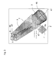
- Fig. 3 illustrates schematically a perspective drawing of a compact OMT according to an embodiment of the invention.
- Fig. 3 shows a linear orthogonally polarized electromagnetic signal entering the waveguide with two orthogonal polarization components, a horizontal polarization component 46 and a vertical polarization component 47.
- One such polarization axis is illustrated by the tilted arrow in Fig. 1 .
- One of two orthogonal polarization components enters or exits the waveguide at the first lengthwise open end at an angle of +45 degrees with respect to the plane defined by the septum 3; the second orthogonal polarization components at an angle of -45 degrees.
- Fig. 3 further shows a circular access 7 coupled to an open end of the first wave guide section 4.
- the OMT divides an orthogonally polarized electro-magnetic signal into two linearly polarized signals wherein the second and third wave guide portions which are isolated from each other at the end of the septum 3 each comprise either the first polarization component 46 or the second polarization component 47 depending on the incoming polarization.
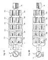
- FIG. 4A illustrates the electric field distribution in the compact OMT in various planes spaced along and perpendicular to the longitudinal axis of the septum according to an embodiment of the invention.
- the incoming signal comprises two linear orthogonally polarized electromagnetic signals 46 and 47.
- Fig. 4A illustrates the electric field distribution for the vertical polarization 46
- Fig. 4B illustrates the electric field distribution for the horizontal polarization 47.
- Polarization is defined as the plane in which the electric field, the E-field, varies.
- Fig. 4A and Fig. 4B Two orthogonal axes are defined as shown in Fig. 4A and Fig. 4B .
- the X and the Y axes lie in an angle of 45 degrees relative to the plane of the septum and orthogonally to each other. Additionally, the X axis and the Y axis are orthogonal to a Z axis (not shown) which is the longitudinal axis of waveguide 2 and the septum 3 and represents the direction of propagation of the electromagnetic wave energy.
- Fig. 4A shows cross-sections 41A ⁇ 44A, 41B ⁇ 44B of a compact OMT of the type illustrated in Fig. 1 at four different points 14 ⁇ 17, i.e. the steps of the septum 3 along the longitudinal axis of the square waveguide 2.
- the arrows inside the sections show the electric field vectors.
- Sections 41A and 41B lie in a transverse plane passing through the point 14; sections 42A and 42B, 43A and 43B, 44A and 44B lie in a transverse plane passing through the points 15, 16 and 17, respectively.
- the first square wave guide portion 4 that is in the portion of the waveguide 2 preceding the septum 3 is to be regarded as transmitting a linear orthogonally polarized signal being propagated away from section 41 and towards section 44.
- the septum 3 of the compact OMT 1 is placed at exactly 45 degrees with respect to the incoming signals 46 (y-axis) and 47 (x-axis).
- the linear orthogonally polarized electromagnetic signals 46 and 47 can be characterized as including orthogonal electric field components E 1 and E 2 , with E 1 being the component parallel to the longitudinal axis of the septum 3 and E 2 being the component that is perpendicular to E 1 .
- the compact OMT is configured to be used with electromagnetic signals with linear polarization, not circular polarization.
- the progress of the electric field component E 1 through the second and third waveguide sections 5 and 6 is illustrated by the field lines in sections 41A to 44A, whereas the progress of the orthogonal E 2 electric field component is illustrated in sections 41B to 44B.
- the E 2 electric field component progresses through the second and third waveguide sections 5 and 6, its direction remains unchanged with increasing height of the septum 3 which is illustrated in sections 41B ⁇ 44B.
- the E 2 component is divided equally by the septum and passes to the two rectangular waveguides 5 and 6.
- the E 1 signal progresses through the second and third waveguide sections 5 and 6, it will rotate smoothly all along the septum 3.
- the metallic and conductive septum 3 causes the E 1 field lines to become parallel with the E 2 field lines and to be divided into two portions oppositely directed on opposite sides of the septum 3 in the second and third waveguide sections 5 and 6 as shown in section 44A of Fig. 4A .
- the septum 3 has also phase-shifting effect in that it induces a differential phase shift of 180 degrees of the E 1 versus the E 2 field components.
- This effect is not illustrated in the sectional views 41A - 44A of Fig. 4A .
- this additional effect of the septum is illustrated in section 45A where a 180° phase shift is added to the E 1 field lines.
- the field lines in section 45A are shifted by 180° compared to the field lines depicted in section 44A.
- This additional 180° phase shift is induced by the septum while the E 1 field lines propagate and rotate along the septum 3.
- this effect is illustrated separately in section 45A.
- this additional phase shift of 180 degrees inverses the direction of the E 1 field so that the E 1 field direction in the third waveguide section 6 cancels the corresponding E 2 field component in the third waveguide section 6, whereas the field components E 1 and E 2 in the second waveguide section 5 are additive.
- a linearly polarized signal is contained in the second waveguide section 5 as shown in section 46.
- Fig. 4B illustrates the same effect for the horizontal polarization.
- a linearly polarized signal is contained in the third waveguide section 6 as shown in Fig. 4B .
- the compact OMT of the invention is thus capable of splitting a linear orthogonally polarized electromagnetic signal into a plurality of linearly polarized frequency components and vice versa using a single rectangular waveguide 2 with an waveguide access or exit of the splitted linear polarized components that is parallel.
- the OMT will also work with any phase shift delay multiple of 180 degrees. However, this will immediately translate in a longer septum and a possible frequency bandwidth reduction.
- Fig. 5 illustrates the phase shift induced by a septum for the frequencies of the frequency band with which an OMT according to an embodiment of the invention is operated.
- the OMT is operated in a frequency band of 11.5 to 12.5 GHz, e.g. which is used for transmissions in telecom satellite applications.
- the Y-axis of the graph shown in Fig. 5 describes the septum-induced phase shift between the field component parallel to the septum and the field component perpendicular to the septum. As depicted in Fig.
- the phase shift in dependence of the frequency follows a curve similar to a parabola with two frequencies 51 and 52 within this frequency band having a phase shift of exactly 180 degrees between components of the linear polarization modes that are perpendicular to said septum and components that are parallel to said septum.
- the phase shift induced by the septum for the frequencies between these two frequencies 51 and 52 is slightly above 180 degrees with a maximum deviation of +2 degrees at 12.08 GHz, whereas the phase shift of the remaining frequencies of the frequency band is slightly below 180 degrees with a maxim deviation of -2 degrees at the borders of the frequency band.
- the phase shift induced by the septum is frequency-dependent.
- the average phase shift induced by the septum is 180 degrees and the deviation from the optimal 180 degrees phase shift lies within a range of +/-2 degrees for the chosen frequency band.
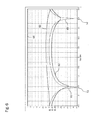
- Fig. 6 illustrates computer simulation results of an OMT depicted in Figs. 1-3 with a circular access portion 7 operated in the Ku- frequency band between 11.5 and 12.5 GHz.
- the lines 61, 62 and 63 measure the return loss, cross-polarization and isolation of the compact OMT in dB for the given frequency band. The lower the dB value, the lower is the undesired noise of the compact OMT.
- the optimal values are achieved for the frequencies 51 and 52 for which a perfect 180 degrees phase shift is induced by the OMT septum.
- the continuous line 63 plots the return loss.
- the worst case value is about -30 dB. This value is the same in the circular common port and in the rectangular one.
- the return loss achieved with the compact OMT according to this embodiment is excellent compared to return loss of side coupling OMTs known from the art in the same band. Those OMTs side coupling OMTs have only a return loss of about -25 dB in the coupled port.
- the dashed line 61 plots the cross-polarization which represents the amount of power that goes from the circular port to the unwanted rectangular port or vice-versa.
- the cross-polarization of the compact OMT depends on how well the stepped septum shifts 180 degrees. Since 180 degrees cannot be achieved in the entire frequency band, the line 61 shows a cross-polar degradation. The worst case value is about -35 dB. Side coupling OMTs normally have -40 to -45 dB of cross-polarization because there is no need of phase shifting in the component.
- the dotted line 62 represents the amount of power that goes from the rectangular port to the other rectangular port. The value obtained is about -39 dB. Other OMTs have a port to port isolation of 50 dB or lower. However, -39 dB of isolation is more than enough for the majority of applications.
- Fig. 6 Due to the geometrical symmetry of the component, the performances presented in Fig. 6 are identical regardless of the polarization (Vertical or Horizontal). The graphs depicted in Fig. 6 show that the compact OMT works as expected, e.g. the RF performances are excellent in terms of Insertion (horizontal dashed line 64 at about 0 dB) and Return loss.
- Fig. 7 illustrates an end view of a feed array assembly 70 of orthomode transducers taken along the lengthwise direction of the compact OMTs 1 according to an embodiment of the invention.
- the compact OMTs 1 with their rectangular waveguide sections 2 having a perfectly parallel waveguide access can be assembled in a very compact and space-saving manner, wherein the OMT waveguides 2 are arranged in parallel.
- the most compact assembly can be achieved if the corresponding center points of the guide sections or longitudinal axis of the waveguide 2 of three adjacent orthomode transducers are substantially equidistant.
Landscapes
- Waveguide Switches, Polarizers, And Phase Shifters (AREA)
- Variable-Direction Aerials And Aerial Arrays (AREA)
Priority Applications (3)
| Application Number | Priority Date | Filing Date | Title |
|---|---|---|---|
| EP09178229A EP2330681A1 (de) | 2009-12-07 | 2009-12-07 | Kompakte OMT-Vorrichtung |
| US13/514,264 US9147921B2 (en) | 2009-12-07 | 2010-11-19 | Compact OMT device |
| PCT/EP2010/007045 WO2011069598A1 (en) | 2009-12-07 | 2010-11-19 | Compact omt device |
Applications Claiming Priority (1)
| Application Number | Priority Date | Filing Date | Title |
|---|---|---|---|
| EP09178229A EP2330681A1 (de) | 2009-12-07 | 2009-12-07 | Kompakte OMT-Vorrichtung |
Publications (1)
| Publication Number | Publication Date |
|---|---|
| EP2330681A1 true EP2330681A1 (de) | 2011-06-08 |
Family
ID=42104485
Family Applications (1)
| Application Number | Title | Priority Date | Filing Date |
|---|---|---|---|
| EP09178229A Ceased EP2330681A1 (de) | 2009-12-07 | 2009-12-07 | Kompakte OMT-Vorrichtung |
Country Status (3)
| Country | Link |
|---|---|
| US (1) | US9147921B2 (de) |
| EP (1) | EP2330681A1 (de) |
| WO (1) | WO2011069598A1 (de) |
Cited By (4)
| Publication number | Priority date | Publication date | Assignee | Title |
|---|---|---|---|---|
| US9147921B2 (en) | 2009-12-07 | 2015-09-29 | European Space Agency | Compact OMT device |
| CN108780952A (zh) * | 2015-09-02 | 2018-11-09 | 中兴通讯股份有限公司 | 具有双偏振的紧凑型天线馈电器 |
| WO2020120715A1 (fr) * | 2018-12-13 | 2020-06-18 | Thales | Panneau de conversion de polarisation |
| FR3146549A1 (fr) | 2023-03-10 | 2024-09-13 | Swissto12 Sa | Transducteur orthomode compact bi-bande à polarisation linéaire |
Families Citing this family (17)
| Publication number | Priority date | Publication date | Assignee | Title |
|---|---|---|---|---|
| US8862050B2 (en) * | 2010-07-30 | 2014-10-14 | Spatial Digital Systems, Inc. | Polarization diversity with portable devices via wavefront muxing techniques |
| US9406987B2 (en) | 2013-07-23 | 2016-08-02 | Honeywell International Inc. | Twist for connecting orthogonal waveguides in a single housing structure |
| EP3114732B1 (de) * | 2014-03-06 | 2020-08-26 | ViaSat, Inc. | Wellenleiterspeisenetzarchitektur für breitbandige duale polarisierte planare horngruppenantennen |
| CN105071006B (zh) * | 2015-08-31 | 2017-09-29 | 北京遥测技术研究所 | 一种新型正交模耦合器 |
| US9947978B1 (en) | 2016-06-13 | 2018-04-17 | Space Systems/Loral, Llc | Orthomode transducer |
| DE102016014385A1 (de) | 2016-12-02 | 2018-06-07 | Kathrein-Werke Kg | Dual polarisierter Hornstrahler |
| EP3333968B1 (de) | 2016-12-12 | 2022-10-05 | European Space Agency (ESA) | Richtkoppler und verfahren zur herstellung davon |
| US10992050B2 (en) * | 2017-05-22 | 2021-04-27 | Mitsubishi Electric Corporation | Antenna device and array antenna device |
| JP6559385B2 (ja) * | 2017-05-26 | 2019-08-14 | 三菱電機株式会社 | 偏波分離回路 |
| US10547117B1 (en) | 2017-12-05 | 2020-01-28 | Unites States Of America As Represented By The Secretary Of The Air Force | Millimeter wave, wideband, wide scan phased array architecture for radiating circular polarization at high power levels |
| US10840573B2 (en) | 2017-12-05 | 2020-11-17 | The United States Of America, As Represented By The Secretary Of The Air Force | Linear-to-circular polarizers using cascaded sheet impedances and cascaded waveplates |
| WO2019203902A2 (en) * | 2017-12-20 | 2019-10-24 | Optisys, LLC | Integrated tracking antenna array |
| US11101573B2 (en) * | 2018-07-02 | 2021-08-24 | Sea Tel, Inc. | Open ended waveguide antenna for one-dimensional active arrays |
| EP3959773B1 (de) * | 2019-06-19 | 2023-06-07 | Viasat, Inc. | Doppelband-septum-polarisator |
| US11658379B2 (en) * | 2019-10-18 | 2023-05-23 | Lockheed Martin Corpora Tion | Waveguide hybrid couplers |
| FR3128590B1 (fr) * | 2021-10-27 | 2024-03-22 | Swissto12 Sa | Module radiofréquence comprenant un réseau de guides d’ondes isophases |
| US12355149B1 (en) * | 2023-06-06 | 2025-07-08 | Utah State University Space Dynamics Laboratory | Waveguide horn antenna |
Citations (4)
| Publication number | Priority date | Publication date | Assignee | Title |
|---|---|---|---|---|
| JPS6399603A (ja) * | 1986-10-15 | 1988-04-30 | Maspro Denkoh Corp | 一次放射器 |
| US6118412A (en) | 1998-11-06 | 2000-09-12 | Victory Industrial Corporation | Waveguide polarizer and antenna assembly |
| JP2002094301A (ja) | 2000-09-12 | 2002-03-29 | Sharp Corp | 直線偏波受信用コンバータ |
| FR2904478A1 (fr) | 2006-07-28 | 2008-02-01 | Alcatel Sa | Dispositif de transduction orthomode a compacite optimisee dans le plan de maille, pour une antenne |
Family Cites Families (3)
| Publication number | Priority date | Publication date | Assignee | Title |
|---|---|---|---|---|
| US4126835A (en) * | 1977-06-20 | 1978-11-21 | Ford Motor Company | Balanced phase septum polarizer |
| US7034771B2 (en) * | 2003-09-10 | 2006-04-25 | The Boeing Company | Multi-beam and multi-band antenna system for communication satellites |
| EP2330681A1 (de) | 2009-12-07 | 2011-06-08 | European Space Agency | Kompakte OMT-Vorrichtung |
-
2009
- 2009-12-07 EP EP09178229A patent/EP2330681A1/de not_active Ceased
-
2010
- 2010-11-19 US US13/514,264 patent/US9147921B2/en active Active
- 2010-11-19 WO PCT/EP2010/007045 patent/WO2011069598A1/en not_active Ceased
Patent Citations (4)
| Publication number | Priority date | Publication date | Assignee | Title |
|---|---|---|---|---|
| JPS6399603A (ja) * | 1986-10-15 | 1988-04-30 | Maspro Denkoh Corp | 一次放射器 |
| US6118412A (en) | 1998-11-06 | 2000-09-12 | Victory Industrial Corporation | Waveguide polarizer and antenna assembly |
| JP2002094301A (ja) | 2000-09-12 | 2002-03-29 | Sharp Corp | 直線偏波受信用コンバータ |
| FR2904478A1 (fr) | 2006-07-28 | 2008-02-01 | Alcatel Sa | Dispositif de transduction orthomode a compacite optimisee dans le plan de maille, pour une antenne |
Non-Patent Citations (3)
| Title |
|---|
| CHATTOPADHYAY ET AL., MICROWAVE AND GUIDED WAVE LETTERS, vol. 8, no. 12, December 1998 (1998-12-01), pages 421 - 423 |
| IHMELS R ET AL: "Field theory design of a corrugated septum OMT", MICROWAVE SYMPOSIUM DIGEST, 1993., IEEE MTT-S INTERNATIONAL ATLANTA, GA, USA 14-18 JUNE 1993, NEW YORK, NY, USA,IEEE, US LNKD- DOI:10.1109/MWSYM.1993.277034, 14 June 1993 (1993-06-14), pages 909 - 912, XP010068369, ISBN: 978-0-7803-1209-8 * |
| TIAN-LING ZHANG ET AL: "A Ka Dual-Band Circular Waveguide Polarizer", ANTENNAS, PROPAGATION & EM THEORY, 2006. ISAPE '06. 7TH INTER NATIONAL SYMPOSIUM ON, IEEE, PI, 1 October 2006 (2006-10-01), pages 1 - 4, XP031080715, ISBN: 978-1-4244-0162-8 * |
Cited By (6)
| Publication number | Priority date | Publication date | Assignee | Title |
|---|---|---|---|---|
| US9147921B2 (en) | 2009-12-07 | 2015-09-29 | European Space Agency | Compact OMT device |
| CN108780952A (zh) * | 2015-09-02 | 2018-11-09 | 中兴通讯股份有限公司 | 具有双偏振的紧凑型天线馈电器 |
| WO2020120715A1 (fr) * | 2018-12-13 | 2020-06-18 | Thales | Panneau de conversion de polarisation |
| FR3090218A1 (fr) * | 2018-12-13 | 2020-06-19 | Thales | Panneau de conversion de polarisation |
| FR3146549A1 (fr) | 2023-03-10 | 2024-09-13 | Swissto12 Sa | Transducteur orthomode compact bi-bande à polarisation linéaire |
| WO2024189480A1 (fr) | 2023-03-10 | 2024-09-19 | Swissto12 Sa | Transducteur orthomode compact bi-bande à polarisation linéaire |
Also Published As
| Publication number | Publication date |
|---|---|
| US20130120086A1 (en) | 2013-05-16 |
| US9147921B2 (en) | 2015-09-29 |
| WO2011069598A1 (en) | 2011-06-16 |
Similar Documents
| Publication | Publication Date | Title |
|---|---|---|
| US9147921B2 (en) | Compact OMT device | |
| US11569554B2 (en) | Orthomode transducer | |
| US10297917B2 (en) | Dual KA band compact high efficiency CP antenna cluster with dual band compact diplexer-polarizers for aeronautical satellite communications | |
| CN101752632B (zh) | 在天线中产生圆极化的紧凑激励组件和形成该组件的方法 | |
| CA2659345C (en) | Compact orthomode transduction device optimized in the mesh plane, for an antenna | |
| US5010348A (en) | Device for exciting a waveguide with circular polarization from a plane antenna | |
| US11367935B2 (en) | Microwave circular polarizer | |
| JP6470930B2 (ja) | 分配器及び平面アンテナ | |
| US20210320415A1 (en) | Microwave antenna system with three-way power dividers/combiners | |
| EP3866256B1 (de) | Wellenleiterleistungsteiler | |
| EP1612880B1 (de) | Wellenleiter-verzweigungsfilter/-polarisierer | |
| EP3935690B1 (de) | Dualband-multimodus-antennenspeisung | |
| EP1158594B1 (de) | Generator für zirkular polarisierte wellen | |
| EP3588668B1 (de) | Antennenvorrichtung | |
| EP3959773B1 (de) | Doppelband-septum-polarisator | |
| CN116130979A (zh) | 一种低副瓣背腔缝隙阵列天线 |
Legal Events
| Date | Code | Title | Description |
|---|---|---|---|
| PUAI | Public reference made under article 153(3) epc to a published international application that has entered the european phase |
Free format text: ORIGINAL CODE: 0009012 |
|
| AK | Designated contracting states |
Kind code of ref document: A1 Designated state(s): AT BE BG CH CY CZ DE DK EE ES FI FR GB GR HR HU IE IS IT LI LT LU LV MC MK MT NL NO PL PT RO SE SI SK SM TR |
|
| AX | Request for extension of the european patent |
Extension state: AL BA RS |
|
| 17P | Request for examination filed |
Effective date: 20111208 |
|
| 17Q | First examination report despatched |
Effective date: 20140131 |
|
| APBK | Appeal reference recorded |
Free format text: ORIGINAL CODE: EPIDOSNREFNE |
|
| APBN | Date of receipt of notice of appeal recorded |
Free format text: ORIGINAL CODE: EPIDOSNNOA2E |
|
| APBR | Date of receipt of statement of grounds of appeal recorded |
Free format text: ORIGINAL CODE: EPIDOSNNOA3E |
|
| APAF | Appeal reference modified |
Free format text: ORIGINAL CODE: EPIDOSCREFNE |
|
| APBT | Appeal procedure closed |
Free format text: ORIGINAL CODE: EPIDOSNNOA9E |
|
| STAA | Information on the status of an ep patent application or granted ep patent |
Free format text: STATUS: THE APPLICATION HAS BEEN REFUSED |
|
| 18R | Application refused |
Effective date: 20220225 |