EP2330703A2 - Agencement destiné à déplacer et fixer un longeron de support et répartiteur d'installation électrique - Google Patents
Agencement destiné à déplacer et fixer un longeron de support et répartiteur d'installation électrique Download PDFInfo
- Publication number
- EP2330703A2 EP2330703A2 EP10189971A EP10189971A EP2330703A2 EP 2330703 A2 EP2330703 A2 EP 2330703A2 EP 10189971 A EP10189971 A EP 10189971A EP 10189971 A EP10189971 A EP 10189971A EP 2330703 A2 EP2330703 A2 EP 2330703A2
- Authority
- EP
- European Patent Office
- Prior art keywords
- housing
- carriage
- locking lever
- arrangement according
- fixing
- Prior art date
- Legal status (The legal status is an assumption and is not a legal conclusion. Google has not performed a legal analysis and makes no representation as to the accuracy of the status listed.)
- Withdrawn
Links
- 238000009434 installation Methods 0.000 title abstract description 5
- 238000010616 electrical installation Methods 0.000 claims abstract description 13
- 238000005516 engineering process Methods 0.000 claims description 2
- 238000010276 construction Methods 0.000 description 4
- 230000006978 adaptation Effects 0.000 description 2
- 238000004519 manufacturing process Methods 0.000 description 2
- 229910000831 Steel Inorganic materials 0.000 description 1
- XAGFODPZIPBFFR-UHFFFAOYSA-N aluminium Chemical compound [Al] XAGFODPZIPBFFR-UHFFFAOYSA-N 0.000 description 1
- 229910052782 aluminium Inorganic materials 0.000 description 1
- 230000001419 dependent effect Effects 0.000 description 1
- 238000006073 displacement reaction Methods 0.000 description 1
- 239000000428 dust Substances 0.000 description 1
- 210000003746 feather Anatomy 0.000 description 1
- 239000010959 steel Substances 0.000 description 1
Images


Classifications
-
- H—ELECTRICITY
- H02—GENERATION; CONVERSION OR DISTRIBUTION OF ELECTRIC POWER
- H02B—BOARDS, SUBSTATIONS OR SWITCHING ARRANGEMENTS FOR THE SUPPLY OR DISTRIBUTION OF ELECTRIC POWER
- H02B1/00—Frameworks, boards, panels, desks, casings; Details of substations or switching arrangements
- H02B1/26—Casings; Parts thereof or accessories therefor
- H02B1/30—Cabinet-type casings; Parts thereof or accessories therefor
-
- H—ELECTRICITY
- H02—GENERATION; CONVERSION OR DISTRIBUTION OF ELECTRIC POWER
- H02B—BOARDS, SUBSTATIONS OR SWITCHING ARRANGEMENTS FOR THE SUPPLY OR DISTRIBUTION OF ELECTRIC POWER
- H02B1/00—Frameworks, boards, panels, desks, casings; Details of substations or switching arrangements
- H02B1/01—Frameworks
- H02B1/012—Details of mechanical connections
Definitions
- the invention relates to an arrangement for adjusting and fixing a support Holmes for an electrical distribution manifold, and an electrical distribution manifold with such a spar.
- An electrical distribution manifold - also referred to as distribution box, fuse box or simply distributor - is a lockable box in which fuse and switching elements for distributing the electrical current are housed. He thus serve to accommodate electrical and / or electronic components of a system, such as a single machine, a manufacturing plant or a building and can be designed, for example, as small distribution, meter cabinets, distribution boards, as a wall or stand distributor or as Isolierstoffverteiler. Depending on the application, electrical distribution manifolds are manufactured from varnished sheet steel, plastic or aluminum sheet in various designs.
- various electrical components or electrical installation equipment such as fuses, circuit breakers, relays, contactors or residual current circuit breaker, are installed so that they are protected by the distributor from external influences such as dust or moisture and from external mechanical force or unauthorized access ,
- the electrical distribution manifold In the interior of the electrical distribution manifold are generally frame structures with brackets for structuring the interior structure and power management systems for connecting the electrical and / or electronic components intended.
- the electrical components or electrical installation equipment are usually attached to mounting rails or DIN rails.
- a standard defines a division unit.
- a variety of installation rows which can be formed by mounting rails, beams or DIN rails, may be provided.
- Rack constructions or distributors must be flexible in order to meet the respective customer requirements.
- the frame of a distributor usually has two side frames and four transverse beams which are welded together. Between the side frame and the cross beams mounting rails and support bars of various lengths, which are connected to each other, can be arranged to customize the manifold for receiving a variety of electrical installation equipment. With fixing rails and supporting bars, the distributors can be subdivided into different levels.
- a distribution frame in which a floor group and a roof group are connected to one another with supporting beams.
- the support bars on the end faces fixed support elements, in particular in the form of locking pins, on.
- a locking pin is rigid, while the locking pin of the other end face is spring-loaded.
- This type of girders is well suited to assemble the frame of the distributor. A change in the position of the support beams relative to the floor or roof group is not readily possible, so that an adaptation to the various distribution types is difficult.
- the DE 202 06 813 U1 another frame construction is known, which at least a first and a second mounting rail and at least one support beam having.
- the carrier beam is arranged between the at least two fastening rails on this.
- the first mounting rail has slot-like openings. Through these slot-like openings projections of the supporting beam for fixing the same can be introduced.
- the projections have a first region of equal width.
- a holding device for example in the form of the elongated slot and a fastening pin, arranged for non-positive or non-positive and positive fastening of the support beam.
- the object of the invention is to provide a frame structure with an arrangement for adjusting and fixing a support beam and a distributor for electrical installation equipment, which allow easy and quick installation.
- a support beam should be easy and quick to install and adjust, so that in addition to short assembly times and high modularity is achieved.
- the inventive arrangement for adjusting and fixing a support spar is provided for an electrical distribution manifold and has a carriage which is fixedly connected to the carrier spar and movable relative to a housing of the electrical installation distributor.
- the carriage on a locking lever which is movably arranged on the carriage and so for cooperation with is formed of the housing, that the support beam is fixable in a predefined position.
- the locking lever is to be loosened, i. from a locking position, in which the support spar is fixed relative to the housing, to spend in an opening position in which the support spar is movable relative to the housing. Subsequently, the support beam can be moved relative to the housing. In this way, a quick and easy installation and a quick and easy adjustability are guaranteed. Furthermore, due to the high modularity, a simple adaptation to different distributor sizes can be realized.
- At least one recess is formed on the housing, into which the locking lever can be latched in the predefined position for fixing the carrier spar.
- the housing has a slide rail, which is firmly connected to the housing, wherein the slide is movable along the slide rail.
- the recess for locking the locking lever is formed on the slide rail.
- the execution of the at least one recess on the slide rail represents a simple and cost-effective way to adapt to different, design-related internal structures of the electrical installation distributor.
- a spring element is provided on the carriage, which is biased such that the locking lever is urged in a preferred position.
- a spring force is exerted on the locking lever, which urges the locking lever securely in the respectively preferred position.
- the carrier beam is fixed in the preferred position relative to the housing. In this way, unintentional release of the supporting beam is prevented by the spring element; the spar is held securely in the fixed position.
- the carrier beam is movable in the preferred position relative to the housing. In this way, the support beam can be adjusted easily and with little effort.
- the locking lever is movable relative to the carriage by means of a set screw.
- the adjusting screw is easy to implement and serves to realize or support the possibility of movement of the locking lever between the locking position and the opening position.
- the locking lever by means of the adjusting screw against the spring force in the open position being held.
- the adjusting screw constitutes an additional securing element for fixing the carrier spar in the locking position.
- the locking lever is designed to be rotatable relative to the carriage.
- the spring element is designed as a torsion spring.
- a rotatable arrangement of the locking lever relative to the carriage represents a simple and cost-effective implementation possibility. In this case, it makes sense to form the spring element as a torsion spring.
- the electrical installation distributor according to the invention for accommodating devices of electrical installation technology has an arrangement for adjusting and fixing a support rail.
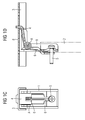
- FIG. 1A to 1D a first embodiment of the arrangement for adjusting and fixing a support Holmes 2 for an electrical distribution manifold is shown schematically.
- the Figures 1A and 1B show the arrangement in a first position in which the support beam 2 is adjustable.
- a carriage 1 On the support beam 2, a carriage 1 is fixed, which is guided along a slide rail 3.
- the slide rail 3 can be formed both on a housing of an electrical installation distributor, as well as part of a frame construction, which is installed in the electrical distribution manifold.
- the slide rail 3 has along a displacement path of the carriage 1 a plurality of recesses 8, which are provided for locking with a locking lever 4 of the carriage 1.
- the locking lever 4 is rotatably mounted on the carriage 1 about a pivot point A and is connected via a torsion spring 6 in the in Fig. 1B shown opening position in which an adjustment of the support beam 2 is possible. Further, an adjusting screw 5 is screwed into the locking lever 4, the screw head is supported on the carriage 1, so that in the open position, a tightening of the adjusting screw 5 results in a rotational movement of the locking lever 4 in the counterclockwise direction. Has the support beam 2 reached by moving along the slide 3 its desired position, the locking lever 4 can be spent using the screw 5 in a locking position in which the locking lever 4 engages in one of the recesses 8. The support beam 2 is thus fixed relative to the slide rail 3. This second position is in the Figures 1C and 1D shown.
- FIGS. 2A to 2D show a second embodiment of the arrangement.
- the arrangement is in turn in the first position in which the support beam 2 is adjustable, shown.
- the Figures 2C and 2D demonstrate the arrangement in turn in the second position in which the support beam 2 is fixed to the slide rail 3.
- the torsion spring 6 is formed in the second embodiment, that the locking lever 4 is urged by the spring force applied by the spring 6 in the locking position in which the locking lever 4 engages in one of the slide rail 3 formed recesses 8.
- the set screw 5 is only so far screwed into the locking lever 4, that it allows a movement of the locking lever 4 about the pivot point A in a limited angular range.
Landscapes
- Engineering & Computer Science (AREA)
- Power Engineering (AREA)
- Casings For Electric Apparatus (AREA)
- Mutual Connection Of Rods And Tubes (AREA)
- Housings And Mounting Of Transformers (AREA)
Applications Claiming Priority (1)
| Application Number | Priority Date | Filing Date | Title |
|---|---|---|---|
| DE102009057065A DE102009057065A1 (de) | 2009-12-04 | 2009-12-04 | Anordnung zum Verstellen und Fixieren eines Tragholmes und Elektroinstallationsverteiler |
Publications (2)
| Publication Number | Publication Date |
|---|---|
| EP2330703A2 true EP2330703A2 (fr) | 2011-06-08 |
| EP2330703A3 EP2330703A3 (fr) | 2013-04-17 |
Family
ID=43413820
Family Applications (1)
| Application Number | Title | Priority Date | Filing Date |
|---|---|---|---|
| EP10189971.4A Withdrawn EP2330703A3 (fr) | 2009-12-04 | 2010-11-04 | Agencement destiné à déplacer et fixer un longeron de support et répartiteur d'installation électrique |
Country Status (2)
| Country | Link |
|---|---|
| EP (1) | EP2330703A3 (fr) |
| DE (1) | DE102009057065A1 (fr) |
Cited By (3)
| Publication number | Priority date | Publication date | Assignee | Title |
|---|---|---|---|---|
| EP2452591A1 (fr) * | 2010-11-11 | 2012-05-16 | Robert L. Fritz | Ensemble support et rail d'équipement |
| WO2016015708A1 (fr) * | 2014-08-01 | 2016-02-04 | Rittal Gmbh & Co. Kg | Système d'armoire |
| EP3439125A1 (fr) * | 2017-07-31 | 2019-02-06 | Eldon Holding Aktiebolag | Armoire électrique pourvue de cadre |
Citations (2)
| Publication number | Priority date | Publication date | Assignee | Title |
|---|---|---|---|---|
| DE29903244U1 (de) | 1999-02-23 | 1999-05-12 | Quante Ag, 42109 Wuppertal | Verteilergestell |
| DE20206813U1 (de) | 2002-04-29 | 2003-05-22 | 3M Innovative Properties Co., St. Paul, Minn. | Eckverbindungsvorrichtung zum Aufbau eines Gehäuserahmens oder eines Gehäuses sowie Gehäuserahmen oder Gehäuse |
Family Cites Families (6)
| Publication number | Priority date | Publication date | Assignee | Title |
|---|---|---|---|---|
| FR2097543A5 (fr) * | 1970-07-10 | 1972-03-03 | Legrand Sa | |
| ES2141034B1 (es) * | 1998-01-15 | 2000-10-16 | Oberon Electronica S A | Regleta telefonica. |
| DE10243717C1 (de) * | 2002-09-20 | 2003-10-30 | Geyer Ag | Einbautiefenverstellbare Verteilergerüstarretierung |
| DE102004032864A1 (de) * | 2004-07-06 | 2006-02-16 | Hager Electro Gmbh | Verteiler der Elektroinstallation |
| ITMI20070024A1 (it) * | 2007-01-10 | 2008-07-11 | Gewiss Spa | Sistema costruttivo a fissaggio rapido ad un quadro elettrico di apparecchi elettrici |
| TWI346861B (en) * | 2008-05-28 | 2011-08-11 | King Slide Works Co Ltd | Slide assembly for a rack |
-
2009
- 2009-12-04 DE DE102009057065A patent/DE102009057065A1/de not_active Ceased
-
2010
- 2010-11-04 EP EP10189971.4A patent/EP2330703A3/fr not_active Withdrawn
Patent Citations (2)
| Publication number | Priority date | Publication date | Assignee | Title |
|---|---|---|---|---|
| DE29903244U1 (de) | 1999-02-23 | 1999-05-12 | Quante Ag, 42109 Wuppertal | Verteilergestell |
| DE20206813U1 (de) | 2002-04-29 | 2003-05-22 | 3M Innovative Properties Co., St. Paul, Minn. | Eckverbindungsvorrichtung zum Aufbau eines Gehäuserahmens oder eines Gehäuses sowie Gehäuserahmen oder Gehäuse |
Cited By (6)
| Publication number | Priority date | Publication date | Assignee | Title |
|---|---|---|---|---|
| EP2452591A1 (fr) * | 2010-11-11 | 2012-05-16 | Robert L. Fritz | Ensemble support et rail d'équipement |
| US8955927B2 (en) | 2010-11-11 | 2015-02-17 | Panduit Corp. | Equipment rail and bracket assembly |
| WO2016015708A1 (fr) * | 2014-08-01 | 2016-02-04 | Rittal Gmbh & Co. Kg | Système d'armoire |
| RU2663203C1 (ru) * | 2014-08-01 | 2018-08-02 | Ритталь Гмбх Унд Ко. Кг | Шкафная система |
| US10201107B2 (en) | 2014-08-01 | 2019-02-05 | Rittal Gmbh & Co. Kg | Cabinet system |
| EP3439125A1 (fr) * | 2017-07-31 | 2019-02-06 | Eldon Holding Aktiebolag | Armoire électrique pourvue de cadre |
Also Published As
| Publication number | Publication date |
|---|---|
| EP2330703A3 (fr) | 2013-04-17 |
| DE102009057065A1 (de) | 2011-06-09 |
Similar Documents
| Publication | Publication Date | Title |
|---|---|---|
| DE102013110477B4 (de) | Durchführungsklemme und elektrische Baueinrichtung | |
| WO2012163716A1 (fr) | Ensemble dispositif de contrôle et de connexion et dispositif de contrôle | |
| EP2561734B1 (fr) | Dispositif permettant de relier de manière pivotante une première partie de boîtier à une seconde partie de boîtier d'une armoire de distribution, et armoire de distribution | |
| EP3200292B1 (fr) | Dispositif de fixation d'un appareil d'automatisation et/ou de communication sur un rail normalise et appareil d'automatisation et/ou de communication | |
| EP1999830B1 (fr) | Module de montage destine a installer un appareil dans une installation de commutation electrique | |
| DE4003260C2 (de) | Adapter für Stromsammelschienensysteme | |
| EP2330703A2 (fr) | Agencement destiné à déplacer et fixer un longeron de support et répartiteur d'installation électrique | |
| DE202015101776U1 (de) | Rangierwabe | |
| DE102013209111B4 (de) | Einspannvorrichtung, insbesondere zur Aufnahme und zum Einspannen eines Bauteils, sowie Einspannsystem mit einer solchen Einspannvorrichtung | |
| DE102010041197B4 (de) | Tragschiene und Elektroinstallationsverteiler | |
| EP3698440B1 (fr) | Pince de fixation | |
| EP1050090B1 (fr) | Element d'assemblage | |
| EP3281253B1 (fr) | Système de rangement en nid d'abeille | |
| DE69506599T2 (de) | Elektrische trägerplatte Installationsvorrichtung mit einem Anschlussflansch | |
| EP3396655A1 (fr) | Panneau led | |
| DE102012203554A1 (de) | Sammelschienenabgreifklemme | |
| EP2582000A1 (fr) | Boîtier d'un appareil électrique ou électronique | |
| WO2017077017A1 (fr) | Module de serrage à fixer à un rail porteur | |
| DE102010033112A1 (de) | Elektroinstallationsgerät | |
| DE102006053415B3 (de) | Befestigungsvorrichtung | |
| DE102018115588B4 (de) | Haltevorrichtung für eine Rangierwabe und Rangierwabe | |
| EP2874250A1 (fr) | Appareil d'installation électrique | |
| DE102019118816B4 (de) | Kontaktträger zum Bereitstellen einer Kontaktierung für eine Verkabelung in einem Fahrzeug | |
| DE202021001123U1 (de) | Zählersteckklemme zm Anschließen von elektrischen Leitungen an einem Stromzähler mit Dreipunktbefestigung | |
| EP3454441B1 (fr) | Boîtier de connexion électrique |
Legal Events
| Date | Code | Title | Description |
|---|---|---|---|
| PUAI | Public reference made under article 153(3) epc to a published international application that has entered the european phase |
Free format text: ORIGINAL CODE: 0009012 |
|
| AK | Designated contracting states |
Kind code of ref document: A2 Designated state(s): AL AT BE BG CH CY CZ DE DK EE ES FI FR GB GR HR HU IE IS IT LI LT LU LV MC MK MT NL NO PL PT RO RS SE SI SK SM TR |
|
| AX | Request for extension of the european patent |
Extension state: BA ME |
|
| RAP1 | Party data changed (applicant data changed or rights of an application transferred) |
Owner name: SIEMENS AKTIENGESELLSCHAFT |
|
| PUAL | Search report despatched |
Free format text: ORIGINAL CODE: 0009013 |
|
| AK | Designated contracting states |
Kind code of ref document: A3 Designated state(s): AL AT BE BG CH CY CZ DE DK EE ES FI FR GB GR HR HU IE IS IT LI LT LU LV MC MK MT NL NO PL PT RO RS SE SI SK SM TR |
|
| AX | Request for extension of the european patent |
Extension state: BA ME |
|
| RIC1 | Information provided on ipc code assigned before grant |
Ipc: H02B 1/30 20060101AFI20130312BHEP |
|
| STAA | Information on the status of an ep patent application or granted ep patent |
Free format text: STATUS: THE APPLICATION IS DEEMED TO BE WITHDRAWN |
|
| 18D | Application deemed to be withdrawn |
Effective date: 20130601 |