EP2330863B1 - Funkkommunikationssystem und Funkkommunikationsverfahren - Google Patents
Funkkommunikationssystem und Funkkommunikationsverfahren Download PDFInfo
- Publication number
- EP2330863B1 EP2330863B1 EP10193461.0A EP10193461A EP2330863B1 EP 2330863 B1 EP2330863 B1 EP 2330863B1 EP 10193461 A EP10193461 A EP 10193461A EP 2330863 B1 EP2330863 B1 EP 2330863B1
- Authority
- EP
- European Patent Office
- Prior art keywords
- radio communication
- radio
- base station
- mode
- communication terminal
- Prior art date
- Legal status (The legal status is an assumption and is not a legal conclusion. Google has not performed a legal analysis and makes no representation as to the accuracy of the status listed.)
- Not-in-force
Links
Images







Classifications
-
- H—ELECTRICITY
- H04—ELECTRIC COMMUNICATION TECHNIQUE
- H04W—WIRELESS COMMUNICATION NETWORKS
- H04W16/00—Network planning, e.g. coverage or traffic planning tools; Network deployment, e.g. resource partitioning or cells structures
- H04W16/24—Cell structures
- H04W16/26—Cell enhancers or enhancement, e.g. for tunnels, building shadow
-
- H—ELECTRICITY
- H04—ELECTRIC COMMUNICATION TECHNIQUE
- H04B—TRANSMISSION
- H04B7/00—Radio transmission systems, i.e. using radiation field
- H04B7/14—Relay systems
- H04B7/15—Active relay systems
- H04B7/155—Ground-based stations
- H04B7/15592—Adapting at the relay station communication parameters for supporting cooperative relaying, i.e. transmission of the same data via direct - and relayed path
-
- H—ELECTRICITY
- H04—ELECTRIC COMMUNICATION TECHNIQUE
- H04B—TRANSMISSION
- H04B7/00—Radio transmission systems, i.e. using radiation field
- H04B7/24—Radio transmission systems, i.e. using radiation field for communication between two or more posts
- H04B7/26—Radio transmission systems, i.e. using radiation field for communication between two or more posts at least one of which is mobile
- H04B7/2603—Arrangements for wireless physical layer control
- H04B7/2606—Arrangements for base station coverage control, e.g. by using relays in tunnels
-
- H—ELECTRICITY
- H04—ELECTRIC COMMUNICATION TECHNIQUE
- H04L—TRANSMISSION OF DIGITAL INFORMATION, e.g. TELEGRAPHIC COMMUNICATION
- H04L1/00—Arrangements for detecting or preventing errors in the information received
- H04L1/0001—Systems modifying transmission characteristics according to link quality, e.g. power backoff
-
- H—ELECTRICITY
- H04—ELECTRIC COMMUNICATION TECHNIQUE
- H04L—TRANSMISSION OF DIGITAL INFORMATION, e.g. TELEGRAPHIC COMMUNICATION
- H04L1/00—Arrangements for detecting or preventing errors in the information received
- H04L2001/0092—Error control systems characterised by the topology of the transmission link
- H04L2001/0097—Relays
Definitions
- the present invention relates to a radio communication system including a radio base station for forming a cell in which at least one relay apparatus is provided and a relay apparatus provided in the cell and to a radio communication method in a radio communication system including the radio base station and the relay apparatus.
- the relay apparatus amplifies a downlink signal received from the radio base station to relay to a radio communication terminal, while further amplifying an uplink signal received from the radio communication terminal to relay to the radio base station.
- Document US 2009/0010215 A1 discloses a system for allocating a wireless resource for a space division multiple access system.
- the system includes channel state recognition unit to recognize a channel state of wireless channels generated among adjacent nodes including a source node, a relay node, and a destination node; and a wireless resource allocation unit to control at least one of an amount of channel state information fed back from the destination node to the source node, and a relay level of a relay signal, the relay signal being generated by relaying a source signal transmitted from the source node, according to the channel state.
- a radio communication system as set forth in claim 1 and a radio communication method as set forth in claim 10 are provided. Embodiments of the invention are claimed in the dependent claims.
- the present Invention was made in view of the above-mentioned respect, and it is an object of the invention to provide a radio base station, a relay apparatus and a radio communication method capable of improving entire throughput in a radio communication system for expanding coverage of the radio base station by relay transmission using the relay apparatus.
- a radio base station is a radio base station for forming a cell in which at least one relay apparatus is provided, and includes an acquiring unit configured to acquire, from each radio communication terminal, reception power information of a first control signal received from the radio base station by the each radio communication terminal and reception power information of a second control signal received from the relay apparatus by the each radio communication terminal, a communication mode determining unit configured to determine a communication mode for each radio communication terminal from among a direct mode for communicating without via the relay apparatus, a relay mode for communicating via the relay apparatus by using a directional beam transmitted between the radio base station and the relay apparatus, and a combined mode for communicating by combining the direct mode and the relay mode, based on the reception power information acquired from the each radio communication terminal, and a communication unit configured to communicate with the each radio communication terminal by using the communication mode determined for the each radio communication terminal.
- a relay apparatus is a relay apparatus provided in a cell formed by a radio base station, and includes a transmission unit configured to transmit a received signal that is amplified with a predetermined amplification factor by using a directional beam for the radio base station when the received signal from a radio communication terminal under the relay apparatus includes identification information of the relay apparatus, while transmitting a received signal that is amplified with a predetermined amplification factor to a radio communication terminal under the relay apparatus when the received signal from the radio base station includes identification information of the relay apparatus.
- a radio communication method is a radio communication method in a radio communication system including a radio base station and at least one relay apparatus provided in a cell formed by the radio base station, and includes the steps in the radio base station of acquiring, from each radio communication terminal, reception power information of a first control signal received from the radio base station by the each radio communication terminal and reception power information of a second control signal received from the relay apparatus by the each radio communication terminal, determining a communication mode for each radio communication terminal from among a direct mode for communicating without via the relay apparatus, a relay mode for communicating via the relay apparatus by using a directional beam transmitted between the radio base station and the relay apparatus, and a combined mode for communicating by combining the direct mode and the relay mode, based on the reception power information acquired from the each radio communication terminal, and communicating with the each radio communication terminal by using the communication mode determined for the each radio communication terminal.
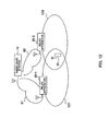
- FIG. 1 is a schematic diagram of a radio communication system according to Embodiment 1.
- the radio communication system includes a radio base station 10, non-reproduction type (Amplify-and-Forward (AF)) relay apparatus 20 provided in a cell C1 of the radio base station 10, and radio communication terminals 30-1 to 30-5.
- AF Auto-and-Forward
- the radio base station 10, relay apparatus 20 and radio communication terminals 30 included in the radio communication system are not limited to the numbers and forms as shown in FIG. 1 .
- the radio base station 10 determines a communication mode for each radio communication terminal 30 from among a direct mode, a relay mode, and a combined mode in which the direct mode and the relay mode are combined. For example, in the radio communication system as shown in FIG. 1 , the radio base station 10 determines a communication mode of the radio communication terminal 30-2 to be the direct mode, a communication mode of the radio communication terminal 30-3 to be the relay mode, communication modes of the radio communication terminals 30-1 and 30-4 to be a capacity increasing mode included in the combined mode, and a communication mode of the radio communication terminal 30-5 to be an area expanding mode included in the combined mode.
- the direct mode is a communication mode in which the radio base station 10 communicates with the radio communication terminal 30 without via the relay apparatus 20. More specifically, in downlink communications, as shown in FIG. 2A , the radio base station 10 transmits a downlink signal for the radio communication terminal 30-2 by using a non-directional beam (not shown in the figure) for the entire cell C1. Meanwhile, not shown in the figure, in uplink communications, the radio base station 10 receives an uplink signal transmitted from the radio communication terminal 30-2. In addition, the radio base station 10 may communicate with the radio communication terminal 30-2 by using a directional beam instead of the non-directional beam.
- the relay mode is a communication mode in which the radio base station 10 communicates with the radio communication terminal 30 via the relay apparatus 20 by using a directional beam transmitted between the radio base station 10 and the relay apparatus 20. More specifically, in downlink communications, as shown in FIG. 2B , the radio base station 10 transmits a downlink signal for the radio communication terminal 30-3 by using a directional beam B0 for the relay apparatus 20. The relay apparatus 20 amplifies the downlink signal received from the radio base station 10 to transmit to the radio communication terminal 30-3. Meanwhile, not shown in the figure, in uplink communications, the relay apparatus 20 amplifies an uplink signal received from the radio communication terminal 30-3, and transmits the amplified signal using a directional beam for the radio base station 10. The radio base station 10 receives the uplink signal transmitted from the relay apparatus 20.
- the combined mode includes the capacity increasing mode in which the direct mode and the relay mode are combined among a plurality of radio communication terminals 30, and the area expanding mode in which the direct mode and the relay mode are combined in one radio communication terminal 30.
- the capacity increasing mode is a communication mode in which the radio base station 10 communicates with one radio communication terminal 30 by the direct mode, while further communicating with another radio communication terminal 30 by the relay mode, by using same radio resources. More specifically, in downlink communications, as shown in FIG. 2C , the radio base station 10 transmits a downlink signal for the radio communication terminal 30-1 by using the non-directional beam (not shown in the figure) for the entire cell C1, while further transmitting a downlink signal for the radio communication terminal 30-4 by using the directional beam B0 for the relay apparatus 20. The relay apparatus 20 amplifies the downlink signal received from the radio base station 10 by using the directional beam B0, and transmits the amplified signal to the radio communication terminal 30-4.
- the relay apparatus 20 in uplink communications, amplifies an uplink signal received from the radio communication terminal 30-4, and transmits the amplified signal using the directional beam aimed at the radio base station 10.
- the radio base station 10 receives the uplink signal transmitted from the relay apparatus 20, while further receiving the uplink signal transmitted from the radio communication terminal 30-1.
- the area expanding mode is a communication mode in which the radio base station 10 communicates with the radio communication terminal 30 by the direct mode, while further communicating with the same radio communication terminal 30 by the relay mode, by using the same radio resources. More specifically, in downlink communications, as shown in FIG. 2D , the radio base station 10 transmits a downlink signal for the radio communication terminal 30-5 by using the non-directional beam (not shown in the figure) for the entire cell C1, while further transmitting the same downlink signal by using the directional beam B0 for the relay apparatus 20. The relay apparatus 20 amplifies the downlink signal received from the radio base station 10 by using the directional beam B0, and transmits the amplified signal to the same radio communication terminal 30-5.
- the relay apparatus 20 amplifies an uplink signal received from the radio communication terminal 30-5, and transmits the amplified signal by using the directional beam for the radio base station 10.
- the radio base station 10 receives the uplink signal transmitted from the relay apparatus 20, while further receiving the same uplink signal transmitted from the radio communication terminal 30-5.
- the radio base station 10 communicates with each radio communication terminal 30 by using the communication mode determined for each radio communication terminal as described above.
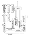
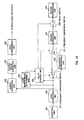
- FIG. 3 is a functional block diagram of the radio base station 10
- FIGs. 4 , 5A and 5B are diagrams to explain the functional configuration of the radio base station 10
- FIG. 6 is a functional block diagram of the relay apparatus 20.
- the radio base station 10 is provided with an array antenna 101 comprised of a plurality of antennas, a training signal generating unit 102, a weight information receiving unit 103, a weight generating unit 104, a weight storing unit 105, a first control signal generating unit 106, a second control signal generating unit 107, a reception power information receiving unit 108, a communication mode determining unit 109, a scheduling unit 110, a transmission buffer 111, and transmission signal generating units 112, 113.
- an array antenna 101 comprised of a plurality of antennas, a training signal generating unit 102, a weight information receiving unit 103, a weight generating unit 104, a weight storing unit 105, a first control signal generating unit 106, a second control signal generating unit 107, a reception power information receiving unit 108, a communication mode determining unit 109, a scheduling unit 110, a transmission buffer 111, and transmission signal generating units 112, 113.
- the training signal generating unit 102 generates a training signal to be transmitted from the array antenna 101 to the relay apparatus 10.
- the training signal is a dummy signal to determine an optimal weight of the directional beam B0 for the relay apparatus 20.
- the weight information receiving unit 103 receives, from the relay apparatus 20, weight information determined based on a reception result of the training signal in the relay apparatus 20.
- the weight generating unit 104 generates the optimal weight of the directional beam B for the relay apparatus 20, based on the weight information received in the weight information receiving unit 103.
- the weight storing unit 105 associates the generated weight with the relay apparatus 20 to store.
- the first control signal generating unit 106 generates a first control signal to be transmitted from the array antenna 101 by using the non-directional beam for the entire cell C1.
- the second control signal generating unit 107 generates a second control signal to be transmitted from the array antenna 101 by using the directional beam B0 for the relay apparatus 20.
- the second control signal includes a relay apparatus ID that is the identification information of the relay apparatus 20. Further, as described later, the second control signal is received by the relay apparatus 20, amplified, and then, transmitted to the radio communication terminal 30 under control of the relay apparatus 20.
- the reception power information receiving unit 108 receives reception power information of the first control signal and the second control signal from the radio communication terminals 30.
- the reception power information indicates reception power of a signal in the radio communication terminal 30, and for example, SINR, etc.
- the reception power information receiving unit 108 receives the reception power (in the unit of dB) of the first control signal and the second control signal from the radio communication terminals 30-1 to 30-5 of FIG. 1 .
- the reception power information receiving unit 108 may receive reception power information of a combined signal of the first control signal and the second control signal, in addition to the reception power information of the first control signal and the reception power information of the second control signal.
- the communication mode determining unit 109 determines the direct mode, the relay mode, the capacity increasing mode or the area expanding mode as the communication mode used in communications with the radio communication terminal 30, based on the reception power information of the first control signal and the second control signal received by the reception power information receiving unit 108.
- the method of determining the communication mode will be described specifically later (see FIG. 8 ), and therefore, descriptions thereof are omitted herein.
- the scheduling unit 110 allocates radio resources to the radio communication terminal 30 for which the communication mode is determined by the communication mode determining unit 109.
- the radio resources may be allocated for each communication mode fixedly or dynamically.
- the radio resources may be allocated for each communication mode in time division or in frequency division.
- radio resources a for the direct mode, radio resources b for the combined mode including the capacity increasing mode and the area expanding mode, and radio resources c for the relay mode are allocated fixedly in the ratio corresponding to traffic amounts of respective communication modes.
- the scheduling unit 110 allocates the radio resources a for the direct mode to the radio communication terminals 30 for which the direct mode is determined, by using the scheduling algorithm such as Round robin and Proportional fair.
- the scheduling unit 110 allocates the radio resources b for the combined mode and the radio resources c for the relay mode to the radio communication terminals 30 for which the combined mode or the relay mode is determined, respectively.
- the radio resources a for the direct mode, radio resources b for the combined mode including the capacity increasing mode and the area expanding mode, and radio resources c for the relay mode are allocated dynamically.
- the scheduling unit 110 selects n radio communication terminals 30 in descending order of the indicator (instantaneous SINR/average SINR) of Proportional fair from among all the radio communication terminals 30.
- the scheduling unit 110 allocates the radio resources a, b and c in the ratio corresponding to the traffic amounts for each communication mode of n selected radio communication terminals 30. For example, when the ratio of the traffic amounts for each communication mode of n selected radio communication terminals 30 is 6:1:3 (direct mode: combined mode: relay mode), the radio resources a, b and c are also allocated in the ratio of 6:1:3.
- the transmission signal generating unit 112 transforms the first control signal generated by the first control signal generating unit 106 into a transmission signal in a predetermined format. Further, the transmission signal generating unit 112 transforms the second control signal generated by the second control signal generating unit 107 into a transmission signal in a predetermined format, based on the weight stored in the weight storing unit 105. The transmission signal generating unit 113 transforms a downlink data signal stored in the transmission buffer 111 into a transmission signal in a predetermined format.
- the relay apparatus 20 is provided with a reception unit 201, a first amplifying unit 202, a weight generating unit 203, a control signal generating unit 204, a first transmission unit 205, a relay control unit 206, a second amplifying unit 207, a relay switch 208, and a second transmission unit 209.
- the reception unit 201 receives a data signal, a control signal and a training signal that are transmitted from the radio base station 10, and a data signal and a control signal that are transmitted from the radio communication terminal 30.
- the first amplifying unit 202 amplifies the downlink signal and uplink signal received by the reception unit 201.
- the weight generating unit 203 generates an optimal weight of the directional beam B0 that is transmitted from the array antenna 101 of the radio base station 10 to the relay apparatus 20, based on a reception result of the training signal received by the reception unit 201.
- the control signal generating unit 204 generates a control signal including weight information indicative of the optimal weight generated by the weight generating unit 203.
- the first transmission unit 205 transmits the control signal including the weight information generated by the weight generating unit 203 to the radio base station 10.
- the relay control unit 206 controls whether or not to relay a received signal, based on whether or not the received signal in the reception unit 201 includes the relay apparatus ID of the relay apparatus 20.
- the relay control unit 206 switches the relay switch 208 ON.
- the relay control unit 206 switches the relay switch 208 OFF.
- the second transmission unit 209 transmits the received signal amplified by the second amplifying unit 207 to the radio communication terminal 30 or the radio base station 10.
- FIG. 7 is a sequence diagram illustrating a radio communication method according to Embodiment 1.
- the relay apparatus 20 is provided in the cell C1 of the radio base station 10
- the radio communication terminals 30-1 and 30-2 are located in the cell C1 of the radio base station 10
- the radio communication terminals 30-3 and 30-4 are located in the cell C2 of the relay apparatus 20
- the radio communication terminal 30-5 is located outside the cells 1 and 2, and the radio communication terminals 30-1 to 30-5 perform downlink communications.
- step S101 the radio base station 10 broadcasts a first control signal by using the non-directional beam for the entire cell 1.
- the radio communication terminals 30-1 to 30-5 receive the first control signal broadcast from the radio base station 10.
- the relay apparatus 20 receives the first control signal broadcast from the radio base station 10, and since the received first control signal does not include the relay apparatus ID of the relay apparatus 20, does not relay the first control signal.
- step S102 the radio base station 10 broadcasts a second control signal including the relay apparatus ID of the relay apparatus 20 by using the directional beam B0 for the relay apparatus 20.
- the relay apparatus 20 receives the second control signal broadcast from the radio base station 10. Since the received second control signal includes the relay apparatus ID of the apparatus 20, the relay apparatus 20 amplifies the second control signal to broadcast.
- the radio communication terminals 30-1 to 30-5 receive the second control signal broadcast from the relay apparatus 20.
- step S103 the radio communication terminals 30-1 to 30-5 measure the reception power of the first control signal received in step S101, and the reception power of the second control signal received in step S102.
- step S104 the radio communication terminals 30-1 to 30-5 notify the radio base station 10 of the reception power information of the first control signal and the second control signal measured in step S103.
- step S105 based on the reception power information of the first control signal and the second control signal notified from the radio communication terminals 30-1 to 30-5, the radio base station 10 determines a communication mode used in communications with each of the radio communication terminals 30-1 to 30-5.
- the operation for the radio base station 10 to determine a communication mode used in communications with each radio communication terminal 30 will be described specifically with reference to FIG. 8.
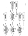
- FIG. 8 is a flowchart illustrating the communication mode determining operation.
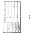
- the radio base station 10 receives the reception power information as shown in FIG. 4 from the radio communication terminals 30-1 to 30-5.
- step S201 based on the reception power information notified from the radio communication terminal 30, the radio base station 10 determines whether or not the reception power of the first control signal or the reception power of the second control signal in the radio communication terminal 30 is a predetermined value or more.
- step S202 the radio base station 10 determines a communication mode of the radio communication terminal 30 to be the "area expanding mode" included in the combined mode.
- the radio base station 10 determines a communication mode of the radio communication terminal 30-5 to be the "area expanding mode"
- step S203 the radio base station 10 determines whether or not the reception power of the first control signal is higher than the reception power of the second control signal.
- step S204 it is determined whether or not the reception power ratio of the first control signal to the second control signal (i.e. reception power of the first control signal/reception power of the second control signal) is a predetermined value or more.
- step S205 the radio base station 10 determines a communication mode of the radio communication terminal 30 to be the "direct mode". For example, in the radio communication terminal 30-2 as shown in FIG. 1 , the reception power (20 dB in FIG. 4 ) of the first control signal is higher than the reception power (2 dB in FIG. 4 ) of the second control signal, and the reception power ratio of the first control signal to the second control signal is a predetermined value (for example, 10) or more. Therefore, in this step, the radio base station 10 determines a communication mode of the radio communication terminal 30-2 to be the "direct mode".
- step S206 the radio base station 10 determines a communication mode of the radio communication terminal 30 to be the "capacity increasing mode" included in the combined mode.
- the radio base station 10 determines a communication mode of the radio communication terminal 30 to be the "direct mode”.
- the reception power (12 dB in FIG. 4 ) of the first control signal is higher than the reception power (8 dB in FIG. 4 ) of the second control signal, and the reception power ratio of the first control signal to the second control signal is less than the predetermined value (for example, 10).
- the radio base station 10 determines a communication mode used in communications with the radio communication terminal 30-1 to be the "capacity increasing mode”.
- step S207 it is determined whether or not the reception power ratio of the second control signal to the first control signal (i.e. reception power of the second control signal/reception power of the first control signal) is a predetermined value or more.
- step S208 the radio base station 10 determines a communication mode of the radio communication terminal 30 to be the "relay mode". For example, in the radio communication terminal 30-3 as shown in FIG. 1 , the reception power (20 dB in FIG. 4 ) of the second control signal is higher than the reception power (2 dB in FIG. 4 ) of the first control signal, and the reception power ratio of the second control signal to the first control signal is a predetermined value (for example, 10) or more. Therefore, in this step, the radio base station 10 determines a communication mode of the radio communication terminal 30-3 to be the "relay mode".
- step S209 the radio base station 10 determines a communication mode of the radio communication terminal 30 to be the "capacity increasing mode". However, when there is no radio communication terminal 30 paired with the radio communication terminal 30 in the "capacity increasing mode", in other words, any other radio communication terminal 30 to proceed to step S206 described above does not exist, the radio base station 10 determines a communication mode of the radio communication terminal 30 to be the "relay mode".
- the reception power (20 dB in FIG. 4 ) of the second control signal is higher than the reception power (10 dB in FIG. 4 ) of the first control signal, and the reception power ratio of the first control signal to the second control signal is less than the predetermined value (for example, 10).
- the radio base station 10 determines a communication mode used in communications with the radio communication terminal 30-4 to be the "capacity increasing mode".
- the radio base station 10 determines communication modes used in communications with the radio communication terminals 30-1 to 30-5.
- the radio base station 10 allocates radio resources to the radio communication terminals 30-1 to 30-5 for which the communication modes are determined in step S105.
- FIG. 9 is a diagram showing an example of radio resources allocation to the radio communication terminals 30 for which the communication modes are determined.
- FIG. 9 shows an example of allocating radio resources to the radio communication terminals of respective communication modes in time division, but radio resources may be allocated in frequency division.
- the radio base station 10 allocates time T1 to the radio communication terminal 30-2 for which the "direct mode” is determined. Further, the radio base station 10 allocates time T2 to the radio communication terminal 30-3 for which the "relay mode” is determined. Furthermore, the radio base station 10 allocates the same time T3 to a plurality of radio communication terminals, 30-1 and 30-4, for which the "capacity increasing mode” is determined. Still furthermore, the radio base station 10 allocates time T4 to the radio communication terminal 30-5 for which the "area expanding mode" is determined.
- the radio base station 10 communicates with the radio communication terminals 30-1 to 30-5 by using the radio resources allocated in step S106.
- FIG. 7 shows the sequence only in downlink communications.
- step S107 the radio base station 10 transmits a data signal for the radio communication terminal 30-2 of the "direct mode" using the radio resources (time T1 in FIG. 9 ) allocated in step S106 by the non-directional beam for the entire cell C1.
- the radio base station 10 does not include the relay apparatus ID of the relay apparatus 20 in the data signal.
- step S108 the radio base station 10 transmits a data signal for the radio communication terminal 30-3 of the "relay mode" using the radio resources (time T2 in FIG. 9 ) allocated in step S106 by the directional beam B0 for the relay apparatus 20.
- the relay apparatus 20 since the radio base station 10 includes the relay apparatus ID of the relay apparatus 20 in the data signal, the relay apparatus 20 amplifies the data signal received from the radio base station 10 to perform secondary transmission.
- the radio base station 10 transmits data signals for the radio communication terminals 30-1 and 30-4 of the "capacity increasing mode" using the radio resources (time T3 in FIG. 9 ) allocated in step S106. More specifically, the radio base station 10 transmits the data signal for the radio communication terminal 30-1 by the non-directional beam for the entire cell C1, while further transmitting the data signal for the radio communication terminal 30-4 by the directional beam B0 for the relay apparatus 20. In addition, the radio base station 10 does not include the relay apparatus ID of the relay apparatus 20 in the data signal for the radio communication terminal 30-1, while including the relay apparatus ID of the relay apparatus 20 in the data signal for the radio communication terminal 30-4. Therefore, the relay apparatus 20 amplifies only the data signal for the radio communication terminal 30-4 to perform secondary transmission.
- step S110 the radio base station 10 transmits data signals for the radio communication terminal 30-5 of the "area expanding mode" using the radio resources (time T4 in FIG. 9 ) allocated in step S106 by the non-directional beam for the entire cell C1 and the directional beam B0 for the relay apparatus 20.
- the radio base station 10 does not include the relay apparatus ID of the relay apparatus 20 in one data signal, while including the relay apparatus ID in the other data signal. Therefore, the relay apparatus 20 amplifies only the other data signal including the relay apparatus ID of the apparatus 20 to perform secondary transmission.
- the radio communication system according to Embodiment 1 in the relay mode, by using the directional beam between the radio base station 10 and the relay apparatus 20, it is possible to reduce interference to other relay apparatuses 20 and other radio communication terminals 30. As a result, it is possible to use a combined mode in which the direct mode and the relay mode are combined as a communication mode of the radio communication terminal 30, and radio resources can be used effectively.
- the relay apparatus 20 is capable of determining whether or not to relay a received signal only by determining whether or not the received signal includes the relay apparatus ID of the apparatus 20. Therefore, in the case where any radio communication terminal 30 does not exist under control of the relay apparatus 20, and the like, it is possible to prevent the relay apparatus 20 from relaying a received signal unnecessarily, and as a result, it is possible to reduce interference to radio communication terminals in other cells and the radio communication terminal 30 of the direct mode.
- Embodiment 1 describes the case where the radio base station 10 communicates with at least one radio communication terminal 30 via a relay apparatus 20 by the relay mode.
- Embodiment 2 describes the case where the radio base station 10 communicates with a plurality of radio communication terminals 30 via different relay apparatuses 20 by the relay mode, while focusing on the difference from Embodiment 1.
- FIG. 10 is a schematic diagram of a radio communication system according to Embodiment 2.
- a plurality of relay apparatuses 20-1 to 20-3 are provided in the cell (not shown in the figure) of the radio base station 10, and radio communication terminals 30-1 to 30-3 are located in cells C21 to C23 of the plurality of relay apparatuses 20-1 to 20-3 respectively.
- the radio base station 10 communicates with the plurality of radio communication terminals 30-1 to 30-3 via different relay apparatuses 20-1 to 20-3 by the relay mode.
- the communications are used directional beams B1 to B3 transmitted between the radio base station 10 and the relay apparatuses 20-1 to 20-3 respectively.
- the same radio resources for example, predetermined time and predetermined frequency
- interference among the directional beams B1 to B3 causes deterioration of communication quality between the radio communication terminals 30-1 to 30-3 and the radio base station 10.
- the scheduling unit 110 of the radio base station 10 performs inter-cell interference control for allocating the same radio resources (for example, predetermined time and predetermined frequency) to radio communication terminals 30 that are selected as described later, so that the communication quality between each of the radio communication terminals 30-1 to 30-3 and the radio base station 10 meets a predetermined value.
- the same radio resources for example, predetermined time and predetermined frequency
- the scheduling unit 110 may randomly select the predetermined number of radio communication terminals 30 from among a plurality of radio communication terminals 30 that performs communications via different relay apparatuses 20, and allocate the same radio resources to the selected plurality of radio communication terminals 30.
- the scheduling unit 110 may sequentially select radio communication terminals 30 to allocate the same radio resources from among a plurality of radio communication terminals 30 that performs communications via different relay apparatuses 20. More specifically, the scheduling unit 110 selects one radio communication terminal 30 from the plurality of radio communication terminals 30 to allocate the radio resources. Then, the scheduling unit 110 selects another radio communication terminal 30 from the plurality of radio communication terminals 30 to allocate the radio resources. When the communication quality of both of the selected two radio communication terminals 30 meets a predetermined value, the scheduling unit 110 allocates the same radio resources to both of the selected radio communication terminals 30. Meanwhile, when the communication quality of both of the selected radio communication terminals does not meet the predetermined value, the scheduling unit 110 does not allocate the radio resources to another radio communication terminal 30. The scheduling unit 110 repeats the above-mentioned operation.
- the scheduling unit 110 allocates time T1 to the radio communication terminals 30-1 and 30-3 which are selected from the plurality of radio communication terminals 30-1 to 30-3 as described above, while allocating time T2 to the radio communication terminal 30-2.
- radio communication terminals 30 to allocate the same radio resources are selected from among a plurality of radio communication terminals 30-1 to 30-3 that communicate with the radio base station 10 via different relay apparatuses 20, and it is thereby possible to prevent interference among the directional beams B1 to B3 used in the communications. Further, as long as the communication quality meets a predetermined value, it is possible to use the same radio resources for a plurality of radio communication terminals 30 of the relay mode, and it is possible to increase throughput in the entire radio communication system.
- Embodiment 3 describes a radio communication system including a plurality of adjacent radio base stations 10 each forming a cell in which the relay apparatus 20 is provided, while focusing on the differences from the above-mentioned Embodiments.
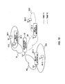
- FIG. 11 is a schematic diagram of a radio communication system according to Embodiment 3 of the invention.
- a plurality of relay apparatuses 20-1 to 20-3 are provided in a cell (not shown in the figure) of a radio base station 10-1, and radio communication terminals 30-1 to 30-3 are located in cells C21 to C23 of the plurality of relay apparatuses 20-1 to 20-3 respectively.
- a plurality of relay apparatuses 20-4 to 20-6 are provided in a cell (not shown in the figure) of a radio base station 10-2 adjacent to the radio base station 10-1, and radio communication terminals 30-4 to 30-6 are located in cells C24 to C26 of the plurality of relay apparatuses 20-4 to 20-6 respectively.
- the radio base station 10-1 communicates with the radio communication terminals 30-1 to 30-3 via different relay apparatuses 20-1 to 20-3 by the relay mode respectively.
- the communications are used directional beams B1 to B3 transmitted between the radio base station 10 and the relay apparatuses 20-1 to 20-3 respectively.
- the radio base station 10-2 communicates with the radio communication terminals 30-4 to 30-6 via different relay apparatuses 20-4 to 20-6 by the relay mode respectively.
- the communications are used directional beams B4 to B6 transmitted between the radio base station 10 and the relay apparatuses 20-4 to 20-6 respectively.
- inter-cell interference occurs in adjacent areas in the cells (not shown in the figure) of the radio base stations 10-1 and 10-2.
- the scheduling units 110 of the adjacent radio base stations 10-1 and 10-2 coordinate the communication modes of radio communication terminals 30 to which the same radio resources are allocated in the adjacent radio base stations 10-1 and 10-2.
- the adjacent radio base stations 10-1 and 10-2 are controlled in advance, so that the allocation ratio and allocated radio resources are the same among the radio resources a for the direct mode, radio resources b for the combined mode including the capacity increasing mode and the area expanding mode, and the radio resources c for the relay mode.
- the scheduling units 110 of the adjacent radio base stations 10-1 to 10-2 assign the radio communication terminals 30 of the same communication mode to the same radio resources.
- the radio resources allocated to a radio communication terminal 30 of the "relay mode" by the scheduling unit 110 of the radio base station 10-1 are also allocated to another radio communication terminal 30 of the "relay mode” by the scheduling unit 110 of the radio base station 10-2, and are not allocated to any radio communication terminal 30 of the other communication mode.
- the communication modes of the radio communication terminals 30 to which the same radio resources are allocated are coordinated, and it is thereby possible to reduce inter-cell interference between the adjacent radio base stations 10-1 and 10-2.
- the scheduling units 110 of the adjacent radio base stations 10-1 and 10-2 may allocate different radio resources to a plurality of radio communication terminals 30 located in the adjacent areas of the cells (not shown in the figure) of the radio base stations 10-1 and 10-2. Such radio resources allocation will specifically be described with reference to FIG. 11 .
- radio communication terminals 30-1 and 30-4 located in the adjacent areas of the cells of the radio base stations 10-1 and 10-2, interference between signals that are transmitted and received among the radio base station 10-1, relay apparatus 20-1 and radio communication terminal 30-1, and signals that are transmitted and received among the radio base station 10-2, relay apparatus 20-2 and radio communication terminal 30-4 causes deterioration of the communication quality of both signals.
- the scheduling units 110 of the radio base stations 10-1 and 10-2 allocate respective different radio resources to a plurality of radio communication terminals, 30-1 and 30-4, positioned in the adjacent areas. For example, in FIG. 11 , the scheduling unit 110 of the radio base station 10-1 allocates time T1 to the radio communication terminal 30-1. Meanwhile, the scheduling unit 110 of the radio base station 10-2 allocates time T2 to the radio communication terminal 30-4.
- the scheduling units 110 of the radio base stations 10-1 and 10-2 may further perform inter-cell interference control described in Embodiment 2. For example, in FIG. 11 , in order to prevent inter-cell interference with the directional beam B1 transmitted in time T1, the scheduling unit 110 of the radio base station 10-1 allocates time T2 to the radio communication terminal 30-2 communicating by using the directional beam B2. Meanwhile, the scheduling unit 110 of the radio base station 10-1 allocates the same time T1 as in the radio communication terminal 30-1 to the radio communication terminal 30-3 communicating by using the directional beam B3 which has a few effects on the directional beam B1. Similarly, in order to prevent inter-cell interference with the directional beam B4 transmitted in time T2, the scheduling unit 110 of the radio base station 10-2 allocates time T1 to the radio communication terminals 30-5 and 30-6 communicating by using directional beams B5 and B6.
- the communication modes of radio communication terminals 30 to which the same resources are allocated are coordinated in between the adjacent base stations 10-1 and 10-2, while respective different radio resources are allocated to a plurality of radio communication terminals 30 located in the adjacent areas of the cells of a plurality of radio base stations 10, and it is thereby possible to prevent inter-cell interference in the adjacent radio base stations 10. Further, as long as inter-cell interference meets a predetermined value, it is possible to share the same radio resources among a plurality of adjacent radio base stations 10, and throughput can thereby be improved.
- Embodiment 4 describes the case where the radio base station 10 communicates with one radio communication terminal 30 for communicating by the relay mode via different relay apparatuses 20, while focusing on the difference.
- FIG. 12 is a schematic diagram of a radio communication system according to Embodiment 4 of the invention.
- a plurality of relay apparatuses 20-1 and 20-2 are provided in the cell of the radio base station 10.
- the relay apparatuses 20-1 and 20-2 respectively form cells C21 and C22, and a radio communication terminal 30 is located in an adjacent area of the cells C21 and C22.
- the radio base station 10 communicates with the radio communication terminal 30 via different relay apparatuses 20-1 and 20-2 by the relay mode.
- the communications are used directional beams B1 and B2 transmitted between the radio base station 10 and the relay apparatuses 20-1 and 20-2 respectively.
- the radio base station 10 communicates with the radio communication terminal 30 via the relay apparatuses 20-1 and 20-2 by the relay mode based on notification from the radio communication terminal 30 (i.e. notification indicating that the radio communication terminal 30 is capable of communicating via the relay apparatuses 20-1 and 20-2). Further, the radio communication terminal 30 receives a second control signal including the relay apparatus ID of the relay apparatus 20-1 from the relay apparatus 20-1, while further receiving a second control signal including the relay apparatus ID of the relay apparatus 20-2 from the relay apparatus 20-2. Based on the reception power of two second control signals received from the relay apparatuses 20-1 and 20-2, the radio communication terminal 30 determines whether or not to be able to communicate via the relay apparatuses 20-1 and 20-2.
- the radio base station 10 is capable of communicating with one radio communication terminal 30 via different relay apparatuses 20 by the relay mode, and it is thereby possible to further expand coverage of the radio base station 10.
- Embodiment 5 describes the case where a plurality of radio base stations 10 communicate with one radio communication terminal 30 for communicating by the relay mode via one relay apparatus 20, while focusing on the difference.
- FIG. 13 is a schematic diagram of a radio communication system according to Embodiment 5 of the invention.
- a relay apparatus 20 is provided in an adjacent area of cells (not shown in the figure) of radio base stations 10-1 and 10-2, and a radio communication terminal 30 is located in the cell C2 of the relay apparatus 20.
- each of the radio base stations 10-1 and 10-2 communicates with the radio communication terminal 30 via one relay apparatus 20 by the relay mode.
- the communications are used directional beams B1 and B2 transmitted between the radio base stations 10-1 and 10-2 and the relay apparatus 20 respectively.
- the relay apparatus 20 notifies surrounding radio base stations 10-1 and 10-2 that communications can be performed via the relay apparatus 20.
- each of the radio base stations 10-1 and 10-2 communicates with the radio communication terminal 30 via the relay apparatus 20.
- a plurality of adjacent radio base stations 10 communicates with one radio communication terminal 30 via one relay apparatus 20 by the relay mode, and it is thereby possible to further expand coverage of the radio base station 10.
- Embodiment 1 describes the radio communication system in which the relay apparatus 20 relays a received signal by using the same frequency as that of the received signal in the case where the radio base station 10 communicates with the radio communication terminal 30 via the relay apparatus 20 by the relay mode.
- Embodiment 6 describes a radio communication system in which the relay apparatus 20 relays a received signal by using the same or different frequency as/from that of the received signal in the same case.
- FIG. 14 is a functional block diagram of the relay apparatus 20 of the radio communication system according to Embodiment 6. As shown in FIG. 14 , in addition to the configuration of Embodiment 1, the relay apparatus 20 is provided with a loop interference determining unit 210, frequency conversion switch 211, and frequency conversion unit 212.
- the loop interference determining unit 210 determines whether or not the reception power of a loop interfering signal is a predetermined value or more with respect to a received signal from the radio base station 10 or radio communication terminal 30. When the loop interference determining unit 210 determines that the reception power of the loop interfering signal is the predetermined value or more, the section 210 notifies the relay control unit 206 that the received signal needs frequency conversion. Meanwhile, when the loop interference determining unit 210 determines that the reception power of the loop interfering signal is less than the predetermined value, the section 210 notifies the relay control unit 206 that the received signal does not need frequency conversion.
- the relay control unit 206 controls the frequency conversion switch 211.
- the section 206 switches the frequency conversion switch 211 ON.
- the section 206 switches the frequency conversion switch 211 OFF.
- the frequency conversion switch 211 is OFF.
- the frequency conversion unit 212 converts the frequency of the received signal amplified in the first amplifying unit 202 into a different frequency.
- the relay apparatus 20 since the relay apparatus 20 relays a received signal by using the same or different frequency as/from that of the received signal, it is possible to prevent the communication quality of a received signal from the radio base station 10 or radio communication terminal 30 from deteriorating, due to a loop interfering signal caused by the case where a transmission signal amplified in the relay apparatus 20 loops into the reception unit 201 of the relay apparatus 20.
- Embodiment 7 describes a radio communication system in which the radio base station 10 performs transmission power control to improve communication quality of communications when the radio base station 10 communicates with the radio communication terminal 30 by the relay mode.
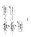
- FIG. 15 is a flowchart illustrating transmission power control that the radio base station 10 performs when the radio base station 10 of the radio communication system according to Embodiment 7 performs downlink communications with the radio communication terminal 30 by the relay mode (see FIG. 10 ).
- the radio base station 10 receives an increasing request of the transmission power from the radio communication terminal 30 that performs downlink communications by the relay mode.
- step S401 the radio base station 10 determines whether or not the reception power of a downlink signal in the relay apparatus 20 is a predetermined value or more.
- step S402 the radio base station 10 determines that propagation conditions between the station 10 and the relay apparatus 20 are good, and that propagation conditions between the relay apparatus 20 and the radio communication terminal 30 deteriorate, and instructs the relay apparatus 20 to increase the amplification factor.
- step S403 the radio base station 10 determines whether or not the interfering power in the relay apparatus 20 is a predetermined value or more.
- step S404 the radio base station 10 determines that interference with a directional beam for another relay apparatus 20 occurs, and changes radio resources to allocate to the downlink signal into other radio resources (for example, another time and another frequency) as described in Embodiment 2. Meanwhile, when the interfering power in the relay apparatus 20 is less than the predetermined value (step S403; No), in step S405 the radio base station 10 determines that it is not necessary to change the radio resources unlike step S404, and increases the transmission power of the directional beam for the relay apparatus 20.
- the radio communication terminal 30 when the radio base station 10 performs uplink communications with the radio communication terminal 30 by the relay mode, the radio communication terminal 30 performs transmission power control performed by the radio base station 10 as shown in FIG. 15 . In this case, it is assumed that the radio communication terminal 30 receives an increasing request of the transmission power from the radio base station 10 that performs uplink communications by the relay mode.
- the amplification factor in the relay apparatus 20 and the transmission power from the radio base station 10 or radio communication terminal 30 is controlled, and it is thereby possible to improve the communication quality between the radio base station 10 and the radio communication terminal 30 by the relay mode.
- the radio base station 10 may use the same frequency channel sounding method in which the radio base station 10 generates an optimal weight based on a channel sounding signal from the relay apparatus 20.
Landscapes
- Engineering & Computer Science (AREA)
- Computer Networks & Wireless Communication (AREA)
- Signal Processing (AREA)
- Quality & Reliability (AREA)
- Mobile Radio Communication Systems (AREA)
- Radio Relay Systems (AREA)
Claims (10)
- Ein Funk-Kommunikationssystem enthaltend eine Funk-Basisstation (10) zum Kommunizieren mit zumindest einem Funk-Kommunikationsendgerät und ein Relais-Gerät (20) befindlich in einer von der Funk-Basisstation (10) gebildeten Zelle, wobei die Funk-Basisstation (10) aufweist:eine Akquirierungseinheit (108), die dazu eingerichtet ist, von jedem Funk-Kommunikationsendgerät eine Empfangsleistungsinformation eines ersten Steuersignals, empfangen durch das jeweilige Funk-Kommunikationsendgerät (30) von der Funk-Basisstation (10), und eine Empfangsleistungsinformation eines zweiten Steuersignals, empfangen durch das jeweilige Funk-Kommunikationsendgerät von dem Relais-Gerät (20), zu akquirieren; und dadurch gekennzeichnet, dass die Funk-Basisstation weiter aufweisteine Kommunikationsmodus-Ermittlungseinheit (109), die dazu eingerichtet ist, für jedes Funk-Kommunikationsendgerät (30) einen Kommunikationsmodus zu ermitteln aus einem direkten Modus zum Kommunizieren nicht über das Relais-Gerät (20), einem Relais-Modus zum Kommunizieren über das Relais-Gerät (20) durch Verwendung eines gerichteten Strahls übertragen zwischen der Funk-Basisstation (10) und dem Relais-Gerät (20), und einem kombinierten Modus zum Kommunizieren durch das Kombinieren des direkten Modus und des Relais-Modus, basierend auf den Empfangsleistungsinformationen akquiriert von dem jeweiligen Funk-Kommunikationsendgerät (30); undeine Kommunikationseinheit (113), die dazu eingerichtet ist, mit jedem Funk-Kommunikationsendgerät unter Verwendung des für das jeweilige Funk-Kommunikationsendgerät ermittelten Kommunikationsmodus zu kommunizieren, unddas Relais-Gerät (20) ist von einem "Verstärken-und-Weiterleiten"-Typ ("Amplify-and-Forward", AF) und enthält eine Relais-Steuereinheit (206), die dazu eingerichtet ist, zu steuern ob oder ob nicht ein von der Funk-Basisstation (10) empfangenes Signal weitergeleitet wird, basierend darauf ob oder ob nicht das empfangene Signal eine Identifizierungsinformation des Relais-Geräts (20) enthält, wobeiein Datensignal, übertragen von der Funk-Basisstation (10) an ein Funk-Kommunikationsendgerät (30), für das von der Kommunikationsmodus-Ermittlungseinheit (109) der Relais-Modus ermittelt wurde, die Identifizierungsinformation des Relais-Geräts (20) enthält, während ein Datensignal, übertragen von der Funk-Basisstation (10) an ein Funk-Kommunikationsendgerät (30), für das von der Kommunikationsmodus-Ermittlungseinheit der direkte Modus ermittelt wurde, die Identifizierungsinformation des Relais-Geräts (20) nicht enthält.
- Das Funk-Kommunikationssystem gemäß Anspruch 1, wobei der kombinierte Modus einen Kapazitäts-Erhöhungs-Modus enthält zum Kommunizieren mit einem Funk-Kommunikationsendgerät (30) mittels des direkten Modus und gleichzeitigem Kommunizieren mit einem anderen Funk-Kommunikationsendgerät (30) mittels des Relais-Modus unter Verwendung derselben Funkressource.
- Das Funk-Kommunikationssystem gemäß Anspruch 1, wobei der kombinierte Modus einen Gebiets-Erweiterungs-Modus enthält zum Kommunizieren mit einem Funk-Kommunikationsendgerät (30) mittels sowohl des direkten Modus als auch des Relais-Modus unter Verwendung derselben Funkressource.
- Das Funk-Kommunikationssystem gemäß Anspruch 1, wobei die Funk-Basisstation weiter aufweist
eine Zuweisungseinheit (110), die dazu eingerichtet ist, jedem Funk-Kommunikationsendgerät (30) gemäß dem für das jeweilige Funk-Kommunikationsendgerät (30) ermittelten Kommunikationsmodus eine Funkressource zuzuweisen. - Das Funk-Kommunikationssystem gemäß Anspruch 4, wobei, wenn die Kommunikationseinheit (113) dazu eingerichtet ist, mit einer Vielzahl von Funk-Kommunikationsendgeräten (30) über verschiedene Relais-Geräte (20) mittels des Relais-Modus zu kommunizieren, die Zuweisungseinheit (110) dazu eingerichtet ist, zumindest einem aus der Vielzahl der Funk-Kommunikationsendgeräte (30) ausgewählten Funk-Kommunikationsendgerät (30) dieselbe Funkressource zuzuweisen, so dass die Kommunikationsqualität eines jeden aus der Vielzahl von Funk-Kommunikationsendgeräten (30) einen vorgegebenen Wert erreicht.
- Das Funk-Kommunikationssystem gemäß Anspruch 4, wobei die Zuweisungseinheit (110) dazu eingerichtet ist, die Kommunikationsmodi für Funk-Kommunikationsendgeräte (30), denen dieselbe Funkressource zugewiesen ist, zwischen der Funk-Basisstation (10-1) und einer benachbarten Funk-Basisstation (10-2) zu koordinieren,
- Das Funk-Kommunikationssystem gemäß Anspruch 1, wobei die Kommunikationseinheit (113) dazu eingerichtet ist, mit einem Funk-Kommunikationsendgerät (30) zur Kommunikation mittels des Relais-Modus über eine Vielzahl von Relais-Geräten (20) zu kommunizieren.
- Das Funk-Kommunikationssystem gemäß Anspruch 1, wobei die Kommunikationseinheit (113) dazu eingerichtet ist, mit einem Funk-Kommunikationsendgerät (30) zum Kommunizieren mittels des Relais-Modus über ein Relais-Gerät (20) zum Senden und Empfangen desselben Signals wie das der Funk-Basisstation (10-1) an/von eine(r) andere(n) Funk-Basisstation (10-2) zu kommunizieren.
- Das Funk-Kommunikationssystem gemäß einem der Ansprüche 1 bis 8, wobei das Relais-Gerät (20) weiter aufweist:eine Schleifeninterferenzsignal-Ermittlungseinheit (210), die dazu eingerichtet ist, zu ermitteln, ob oder ob nicht die Empfangsleistung eines Schleifeninterferenzsignals in dem empfangenen Signal ein vorgegebener Wert oder mehr ist; undeine Frequenz-Konvertierungs-Einheit (211), die dazu eingerichtet ist, eine Frequenz des empfangenen Signals in eine andere Frequenz zu konvertieren, wenn die Empfangsleistung des Schleifeninterferenzsignals in dem empfangenen Signal der vorgegebene Wert oder mehr ist.
- Ein Funk-Kommunikationsverfahren in einem Funk-Kommunikationssystem enthaltend eine Funk-Basisstation (10) und mindestens ein Relais-Gerät (20), dem eine Identifizierungsinformation zugeordnet ist und das sich in einer von der Funk-Basisstation (10) gebildeten Zelle befindet, zum Kommunizieren mit zumindest einem Funk-Kommunikationsendgerät, aufweisend:in der Funk-Basisstation (10), das Akquirieren einer Empfangsleistungsinformation eines ersten Steuersignals empfangen durch das jeweilige Funk-Kommunikationsendgerät (30) von der Funk-Basisstation (10) und einer Empfangsleistungsinformation eines zweiten Steuersignals empfangen durch das jeweilige Funk-Kommunikationsendgerät von dem Relais-Gerät (20) von jedem Funk-Kommunikationsendgerät; dadurch gekennzeichnet, dassin der Funk-Basisstation (10), das Ermitteln (30) eines Kommunikationsmodus aus einem direkten Modus zum Kommunizieren nicht über das Relais-Gerät (20), einem Relais-Modus zum Kommunizieren über das Relais-Gerät (20) durch Verwendung eines gerichteten Strahls übertragen zwischen der Funk-Basisstation (10) und dem Relais-Gerät (20), und einem kombinierten Modus zum Kommunizieren durch das Kombinieren des direkten Modus und des Relais-Modus, für jedes Funk-Kommunikationsendgerät basierend auf den Empfangsleistungsinformationen akquiriert von dem jeweiligen Funk-Kommunikationsendgerät (30); undin der Funk-Basisstation (10), das Kommunizieren mit jedem Funk-Kommunikationsendgerät (30) unter Verwendung des für das jeweilige Funk-Kommunikationsendgerät (30) ermittelten Kommunikationsmodus, undin dem Relais-Gerät (20) von einem "Verstärken-und-Weiterleiten"-Typ ("Amplify-and-Forward, AF), das Steuern, ob oder ob nicht ein von der Funk-Basisstation (10) empfangenes Signal weitergeleitet wird, basierend darauf ob oder ob nicht das empfangene Signal eine Identifizierungsinformation des Relais-Geräts (20) enthält; wobeiein Datensignal, übertragen von der Funk-Basisstation (10) an ein Funk-Kommunikationsendgerät (30), für das von der Kommunikationsmodus-Ermittlungseinheit (109)der Relais-Modus ermittelt wurde, die Identifizierungsinformation des Relais-Geräts (20) enthält, während ein Datensignal, übertragen von der Funk-Basisstation (10) an ein Funk-Kommunikationsendgerät (30), für das von der Kommunikationsmodus-Ermittlungseinheit der direkte Modus ermittelt wurde, die Identifizierungsinformation des Relais-Geräts (20) nicht enthält.
Applications Claiming Priority (1)
| Application Number | Priority Date | Filing Date | Title |
|---|---|---|---|
| JP2009275760A JP4990343B2 (ja) | 2009-12-03 | 2009-12-03 | 無線通信システム及び無線通信方法 |
Publications (3)
| Publication Number | Publication Date |
|---|---|
| EP2330863A2 EP2330863A2 (de) | 2011-06-08 |
| EP2330863A3 EP2330863A3 (de) | 2012-06-13 |
| EP2330863B1 true EP2330863B1 (de) | 2013-07-10 |
Family
ID=43708948
Family Applications (1)
| Application Number | Title | Priority Date | Filing Date |
|---|---|---|---|
| EP10193461.0A Not-in-force EP2330863B1 (de) | 2009-12-03 | 2010-12-02 | Funkkommunikationssystem und Funkkommunikationsverfahren |
Country Status (4)
| Country | Link |
|---|---|
| US (1) | US20110136525A1 (de) |
| EP (1) | EP2330863B1 (de) |
| JP (1) | JP4990343B2 (de) |
| CN (1) | CN102088710A (de) |
Families Citing this family (22)
| Publication number | Priority date | Publication date | Assignee | Title |
|---|---|---|---|---|
| CN103329606A (zh) * | 2011-03-01 | 2013-09-25 | 诺基亚西门子网络公司 | 在具有不同接入限制的接入节点之间共享无线电资源 |
| GB2491857B (en) * | 2011-06-14 | 2015-07-29 | Sca Ipla Holdings Inc | Wireless communications system and method |
| GB2491900B (en) * | 2011-06-17 | 2014-04-30 | Toshiba Res Europ Ltd | Wireless communications methods and apparatus |
| JP2013074399A (ja) * | 2011-09-27 | 2013-04-22 | Kyocera Corp | 中継装置及び通信制御方法 |
| JP2013074529A (ja) * | 2011-09-28 | 2013-04-22 | Kyocera Corp | 中継装置及び通信制御方法 |
| GB2503923A (en) * | 2012-07-12 | 2014-01-15 | Nec Corp | Coordinated multipoint transmissions to a relay node |
| CN103974273B (zh) * | 2013-02-06 | 2018-11-13 | 中兴通讯股份有限公司 | 干扰关系的获取方法及系统 |
| US9414394B2 (en) * | 2013-08-12 | 2016-08-09 | Qualcomm Incorporated | Avoiding suspended transmission during network listen for small cell base stations |
| EP3087796B1 (de) * | 2013-12-27 | 2021-04-14 | Telefonaktiebolaget LM Ericsson (publ) | Verfahren und funkzugangspunkt zur handhabung von kommunikationen zwischen drahtlosen vorrichtungen |
| US9548848B1 (en) * | 2015-02-19 | 2017-01-17 | Mbit Wireless, Inc. | Method and apparatus for reduced complexity CQI feedback in wireless communication systems |
| CN107534482B (zh) * | 2015-05-15 | 2021-01-29 | 索尼公司 | 移动通信系统、通信终端和方法 |
| JP6491962B2 (ja) * | 2015-06-19 | 2019-03-27 | 株式会社日立製作所 | 中継装置及び通信方法 |
| US20190045433A1 (en) * | 2015-09-18 | 2019-02-07 | Nec Corporation | Relay device, access node, and relay device control method |
| JP7162562B2 (ja) * | 2019-03-29 | 2022-10-28 | 本田技研工業株式会社 | 中継装置及びプログラム |
| US12107661B2 (en) * | 2019-08-01 | 2024-10-01 | Qualcomm Incorporated | Control method for smart repeaters |
| US12047999B2 (en) | 2019-08-01 | 2024-07-23 | Qualcomm Incorporated | Access procedure configuration of a millimeter wave repeater |
| US12101165B2 (en) | 2019-08-01 | 2024-09-24 | Qualcomm Incorporated | Access procedure of smart directional repeaters |
| CN113382423B (zh) * | 2020-03-09 | 2023-08-22 | 维沃移动通信有限公司 | 信号传输方法、信息指示方法和相关设备 |
| US12309830B2 (en) | 2020-03-23 | 2025-05-20 | Qualcomm Incorporated | Access procedure configuration of a millimeter wave repeater |
| CN116508270B (zh) * | 2020-10-30 | 2026-05-05 | 联发科技(新加坡)私人有限公司 | 用于下行链路传输和上行链路传输的中继器及控制方法 |
| US11770171B2 (en) * | 2021-06-29 | 2023-09-26 | Qualcomm Incorporated | Reconfigurable intelligent surface link identification |
| US20250233653A1 (en) * | 2022-04-22 | 2025-07-17 | Mitsubishi Electric Corporation | Communication system |
Family Cites Families (24)
| Publication number | Priority date | Publication date | Assignee | Title |
|---|---|---|---|---|
| US6748212B2 (en) * | 1999-12-29 | 2004-06-08 | Airnet Communications Corporation | Method and apparatus for backhaul link diagnostic in a wireless repeater system |
| US6937558B2 (en) * | 2000-02-29 | 2005-08-30 | Kabushiki Kaisha Toshiba | Transmitter apparatus and receiver apparatus and base station making use of orthogonal frequency division multiplexing and spectrum spreading |
| ES2395561T3 (es) * | 2003-05-15 | 2013-02-13 | Telefonaktiebolaget Lm Ericsson (Publ) | Cancelación de interferencias en redes de retransmisión inalámbricas |
| US7406295B1 (en) * | 2003-09-10 | 2008-07-29 | Sprint Spectrum L.P. | Method for dynamically directing a wireless repeater |
| JP4153866B2 (ja) * | 2003-11-27 | 2008-09-24 | 株式会社東芝 | 無線通信システム、基地局装置及び無線通信方法 |
| US8185044B2 (en) * | 2004-03-31 | 2012-05-22 | Rockstar Bidco Lp | Multi-hop load balancing |
| CN101167294B (zh) * | 2005-02-17 | 2013-07-17 | 艾利森电话股份有限公司 | 用于协同中继的方法和装置 |
| KR100975743B1 (ko) * | 2005-07-14 | 2010-08-12 | 삼성전자주식회사 | 무선 통신 시스템에서 신호 릴레이 방법 및 시스템 |
| WO2007055544A2 (en) * | 2005-11-11 | 2007-05-18 | Lg Electronics Inc. | Method of controlling relay communication |
| JP4847540B2 (ja) * | 2005-11-29 | 2011-12-28 | テレフオンアクチーボラゲット エル エム エリクソン(パブル) | 無線マルチホップ中継ネットワークにおけるスケジューリング |
| KR101358469B1 (ko) * | 2006-02-07 | 2014-02-06 | 엘지전자 주식회사 | 무선 네트워크(network) 안에서 상향(uplink)및 하향(downlink) 대역폭(bandwidth)의선택 및 신호 방법 |
| KR101210332B1 (ko) * | 2006-09-27 | 2012-12-10 | 삼성전자주식회사 | 증폭-순방향 릴레이 시스템의 릴레이 전력 제어 장치 및 그방법 |
| US8149726B2 (en) * | 2007-01-04 | 2012-04-03 | Industrial Technology Research Institute | Wireless communication system and method |
| KR100973670B1 (ko) * | 2007-03-21 | 2010-08-04 | 삼성전자주식회사 | 중계 방식의 광대역 무선통신 시스템에서 중계 링크 운용장치 및 방법 |
| JP2008244836A (ja) * | 2007-03-27 | 2008-10-09 | Toshiba Corp | 基地局、無線通信システム及び無線通信方法 |
| US8045497B2 (en) * | 2007-07-02 | 2011-10-25 | Samsung Electronics Co., Ltd. | Method of allocating wireless resource for space division multiple access communication and wireless resource allocation system of enabling the method |
| US20090116422A1 (en) * | 2007-11-02 | 2009-05-07 | Chia-Chin Chong | Method and system for opportunistic hybrid relay selection scheme for downlink transmission |
| US8718541B2 (en) * | 2007-12-31 | 2014-05-06 | Intel Corporation | Techniques for optimal location and configuration of infrastructure relay nodes in wireless networks |
| US8861423B2 (en) * | 2008-01-18 | 2014-10-14 | Intel Corporation | Interference mitigation by overhearing |
| JP2009232256A (ja) * | 2008-03-24 | 2009-10-08 | Toshiba Corp | 基地局、無線通信方法および通信プログラム |
| JP5061383B2 (ja) | 2008-05-13 | 2012-10-31 | 本田技研工業株式会社 | 変速機の変速制御装置 |
| JP2010016674A (ja) * | 2008-07-04 | 2010-01-21 | Fujitsu Ltd | 無線通信装置、無線通信システム、及び無線通信方法 |
| JP5187132B2 (ja) * | 2008-10-21 | 2013-04-24 | 富士通株式会社 | 通信装置、通信システムおよび通信方法 |
| US20110103269A1 (en) * | 2009-10-29 | 2011-05-05 | Industrial Technology Research Institute | Wireless communication system and relay station and wireless communication device thereof |
-
2009
- 2009-12-03 JP JP2009275760A patent/JP4990343B2/ja active Active
-
2010
- 2010-11-30 US US12/956,415 patent/US20110136525A1/en not_active Abandoned
- 2010-12-01 CN CN2010105684659A patent/CN102088710A/zh active Pending
- 2010-12-02 EP EP10193461.0A patent/EP2330863B1/de not_active Not-in-force
Also Published As
| Publication number | Publication date |
|---|---|
| JP2011120015A (ja) | 2011-06-16 |
| CN102088710A (zh) | 2011-06-08 |
| US20110136525A1 (en) | 2011-06-09 |
| EP2330863A3 (de) | 2012-06-13 |
| EP2330863A2 (de) | 2011-06-08 |
| JP4990343B2 (ja) | 2012-08-01 |
Similar Documents
| Publication | Publication Date | Title |
|---|---|---|
| EP2330863A2 (de) | Funkbasisstation, Relaisvorrichtung und Funkkommunikationsverfahren | |
| JP4922426B2 (ja) | 反射板装置、無線基地局及び無線通信方法 | |
| KR102198348B1 (ko) | 무선 통신 시스템에서 릴레이 링크 셋업 방법 및 장치 | |
| KR101434585B1 (ko) | 협력 통신 릴레이를 이용하여 데이터를 전송하는 통신시스템 | |
| KR100953262B1 (ko) | 무선 통신 시스템 및 무선 통신 제어 방법 | |
| EP1418779B1 (de) | Kommunikationsregelungsverfahren und Vorrichtung in einem Mobilfunksystem | |
| EP3059877B1 (de) | Strahlformungsverfahren von millimeterwellenkommunikation und basisstation sowie benutzergerät damit | |
| US9161289B2 (en) | Selection of dynamic relays for cooperative communications in a mobile network | |
| KR101075964B1 (ko) | 통신 시스템에서 다중 링크 중계 장치 및 방법 | |
| US7239619B2 (en) | Mobile communication system, base station, mobile station, and cell control method | |
| JPH09215052A (ja) | 空間分割多元接続無線通信システムおよび同システムにおいてチャネルを割り当てる方法 | |
| KR100605441B1 (ko) | 무선 기지 장치, 통신 채널 할당 방법 및 컴퓨터 판독가능 매체 | |
| US7818009B2 (en) | Cellular channel allocation scheme with multi-user detection | |
| JP2001148649A (ja) | 無線基地局 | |
| JP3213601B2 (ja) | 無線基地局 | |
| JP2008113450A (ja) | 無線通信用アダプティブアレイ及びアダプティブアレイを用いた無線通信システム | |
| JP2002319894A (ja) | 移動通信システムにおける通信制御方法及び装置 | |
| JP2002232350A (ja) | 無線通信方法及びビーム方向可変型アンテナを用いた無線通信システム | |
| JPH1174831A (ja) | 無線通信方法、無線通信システム、基地局及び移動端末 | |
| KR20060081194A (ko) | 다중 안테나 시스템에서 섹터 구성 장치 및 방법 | |
| Song et al. | A survey of single and multi-hop link schedulers for mmWave wireless systems | |
| JP2000023238A (ja) | 移動通信システムにおけるセル構成法、無線アクセス方式及び移動機 | |
| KR101397521B1 (ko) | 편파 특성을 이용한 협력 전송 시스템 및 방법 | |
| JP2689671B2 (ja) | 移動通信システム | |
| JP2008205743A (ja) | 制御装置 |
Legal Events
| Date | Code | Title | Description |
|---|---|---|---|
| PUAI | Public reference made under article 153(3) epc to a published international application that has entered the european phase |
Free format text: ORIGINAL CODE: 0009012 |
|
| AK | Designated contracting states |
Kind code of ref document: A2 Designated state(s): AL AT BE BG CH CY CZ DE DK EE ES FI FR GB GR HR HU IE IS IT LI LT LU LV MC MK MT NL NO PL PT RO RS SE SI SK SM TR |
|
| AX | Request for extension of the european patent |
Extension state: BA ME |
|
| RIC1 | Information provided on ipc code assigned before grant |
Ipc: H04W 16/26 20090101AFI20120222BHEP |
|
| PUAL | Search report despatched |
Free format text: ORIGINAL CODE: 0009013 |
|
| AK | Designated contracting states |
Kind code of ref document: A3 Designated state(s): AL AT BE BG CH CY CZ DE DK EE ES FI FR GB GR HR HU IE IS IT LI LT LU LV MC MK MT NL NO PL PT RO RS SE SI SK SM TR |
|
| AX | Request for extension of the european patent |
Extension state: BA ME |
|
| RIC1 | Information provided on ipc code assigned before grant |
Ipc: H04W 16/26 20090101AFI20120510BHEP Ipc: H04B 7/15 20060101ALI20120510BHEP |
|
| 17P | Request for examination filed |
Effective date: 20120718 |
|
| REG | Reference to a national code |
Ref country code: DE Ref legal event code: R079 Ref document number: 602010008378 Country of ref document: DE Free format text: PREVIOUS MAIN CLASS: H04W0088040000 Ipc: H04W0016260000 |
|
| GRAP | Despatch of communication of intention to grant a patent |
Free format text: ORIGINAL CODE: EPIDOSNIGR1 |
|
| RIC1 | Information provided on ipc code assigned before grant |
Ipc: H04B 7/155 20060101ALI20130109BHEP Ipc: H04W 16/26 20090101AFI20130109BHEP Ipc: H04L 1/00 20060101ALN20130109BHEP Ipc: H04B 7/26 20060101ALI20130109BHEP |
|
| RIN1 | Information on inventor provided before grant (corrected) |
Inventor name: SHEN, JIYUN Inventor name: OHYA, TOMOYUKI Inventor name: FUJII, HIROMASA |
|
| GRAS | Grant fee paid |
Free format text: ORIGINAL CODE: EPIDOSNIGR3 |
|
| GRAA | (expected) grant |
Free format text: ORIGINAL CODE: 0009210 |
|
| AK | Designated contracting states |
Kind code of ref document: B1 Designated state(s): AL AT BE BG CH CY CZ DE DK EE ES FI FR GB GR HR HU IE IS IT LI LT LU LV MC MK MT NL NO PL PT RO RS SE SI SK SM TR |
|
| REG | Reference to a national code |
Ref country code: GB Ref legal event code: FG4D |
|
| REG | Reference to a national code |
Ref country code: AT Ref legal event code: REF Ref document number: 621550 Country of ref document: AT Kind code of ref document: T Effective date: 20130715 Ref country code: CH Ref legal event code: EP |
|
| REG | Reference to a national code |
Ref country code: IE Ref legal event code: FG4D |
|
| REG | Reference to a national code |
Ref country code: DE Ref legal event code: R096 Ref document number: 602010008378 Country of ref document: DE Effective date: 20130905 |
|
| PG25 | Lapsed in a contracting state [announced via postgrant information from national office to epo] |
Ref country code: SI Free format text: LAPSE BECAUSE OF FAILURE TO SUBMIT A TRANSLATION OF THE DESCRIPTION OR TO PAY THE FEE WITHIN THE PRESCRIBED TIME-LIMIT Effective date: 20130710 |
|
| REG | Reference to a national code |
Ref country code: AT Ref legal event code: MK05 Ref document number: 621550 Country of ref document: AT Kind code of ref document: T Effective date: 20130710 |
|
| REG | Reference to a national code |
Ref country code: NL Ref legal event code: VDEP Effective date: 20130710 |
|
| REG | Reference to a national code |
Ref country code: LT Ref legal event code: MG4D |
|
| PG25 | Lapsed in a contracting state [announced via postgrant information from national office to epo] |
Ref country code: PT Free format text: LAPSE BECAUSE OF FAILURE TO SUBMIT A TRANSLATION OF THE DESCRIPTION OR TO PAY THE FEE WITHIN THE PRESCRIBED TIME-LIMIT Effective date: 20131111 Ref country code: HR Free format text: LAPSE BECAUSE OF FAILURE TO SUBMIT A TRANSLATION OF THE DESCRIPTION OR TO PAY THE FEE WITHIN THE PRESCRIBED TIME-LIMIT Effective date: 20130710 Ref country code: LT Free format text: LAPSE BECAUSE OF FAILURE TO SUBMIT A TRANSLATION OF THE DESCRIPTION OR TO PAY THE FEE WITHIN THE PRESCRIBED TIME-LIMIT Effective date: 20130710 Ref country code: AT Free format text: LAPSE BECAUSE OF FAILURE TO SUBMIT A TRANSLATION OF THE DESCRIPTION OR TO PAY THE FEE WITHIN THE PRESCRIBED TIME-LIMIT Effective date: 20130710 Ref country code: BE Free format text: LAPSE BECAUSE OF FAILURE TO SUBMIT A TRANSLATION OF THE DESCRIPTION OR TO PAY THE FEE WITHIN THE PRESCRIBED TIME-LIMIT Effective date: 20130710 Ref country code: SE Free format text: LAPSE BECAUSE OF FAILURE TO SUBMIT A TRANSLATION OF THE DESCRIPTION OR TO PAY THE FEE WITHIN THE PRESCRIBED TIME-LIMIT Effective date: 20130710 Ref country code: IS Free format text: LAPSE BECAUSE OF FAILURE TO SUBMIT A TRANSLATION OF THE DESCRIPTION OR TO PAY THE FEE WITHIN THE PRESCRIBED TIME-LIMIT Effective date: 20131110 Ref country code: CY Free format text: LAPSE BECAUSE OF FAILURE TO SUBMIT A TRANSLATION OF THE DESCRIPTION OR TO PAY THE FEE WITHIN THE PRESCRIBED TIME-LIMIT Effective date: 20130717 Ref country code: NO Free format text: LAPSE BECAUSE OF FAILURE TO SUBMIT A TRANSLATION OF THE DESCRIPTION OR TO PAY THE FEE WITHIN THE PRESCRIBED TIME-LIMIT Effective date: 20131010 |
|
| PG25 | Lapsed in a contracting state [announced via postgrant information from national office to epo] |
Ref country code: GR Free format text: LAPSE BECAUSE OF FAILURE TO SUBMIT A TRANSLATION OF THE DESCRIPTION OR TO PAY THE FEE WITHIN THE PRESCRIBED TIME-LIMIT Effective date: 20131011 Ref country code: ES Free format text: LAPSE BECAUSE OF FAILURE TO SUBMIT A TRANSLATION OF THE DESCRIPTION OR TO PAY THE FEE WITHIN THE PRESCRIBED TIME-LIMIT Effective date: 20131021 Ref country code: NL Free format text: LAPSE BECAUSE OF FAILURE TO SUBMIT A TRANSLATION OF THE DESCRIPTION OR TO PAY THE FEE WITHIN THE PRESCRIBED TIME-LIMIT Effective date: 20130710 Ref country code: LV Free format text: LAPSE BECAUSE OF FAILURE TO SUBMIT A TRANSLATION OF THE DESCRIPTION OR TO PAY THE FEE WITHIN THE PRESCRIBED TIME-LIMIT Effective date: 20130710 Ref country code: FI Free format text: LAPSE BECAUSE OF FAILURE TO SUBMIT A TRANSLATION OF THE DESCRIPTION OR TO PAY THE FEE WITHIN THE PRESCRIBED TIME-LIMIT Effective date: 20130710 Ref country code: PL Free format text: LAPSE BECAUSE OF FAILURE TO SUBMIT A TRANSLATION OF THE DESCRIPTION OR TO PAY THE FEE WITHIN THE PRESCRIBED TIME-LIMIT Effective date: 20130710 |
|
| PG25 | Lapsed in a contracting state [announced via postgrant information from national office to epo] |
Ref country code: CY Free format text: LAPSE BECAUSE OF FAILURE TO SUBMIT A TRANSLATION OF THE DESCRIPTION OR TO PAY THE FEE WITHIN THE PRESCRIBED TIME-LIMIT Effective date: 20130710 |
|
| PG25 | Lapsed in a contracting state [announced via postgrant information from national office to epo] |
Ref country code: RO Free format text: LAPSE BECAUSE OF FAILURE TO SUBMIT A TRANSLATION OF THE DESCRIPTION OR TO PAY THE FEE WITHIN THE PRESCRIBED TIME-LIMIT Effective date: 20130710 Ref country code: SK Free format text: LAPSE BECAUSE OF FAILURE TO SUBMIT A TRANSLATION OF THE DESCRIPTION OR TO PAY THE FEE WITHIN THE PRESCRIBED TIME-LIMIT Effective date: 20130710 Ref country code: CZ Free format text: LAPSE BECAUSE OF FAILURE TO SUBMIT A TRANSLATION OF THE DESCRIPTION OR TO PAY THE FEE WITHIN THE PRESCRIBED TIME-LIMIT Effective date: 20130710 Ref country code: EE Free format text: LAPSE BECAUSE OF FAILURE TO SUBMIT A TRANSLATION OF THE DESCRIPTION OR TO PAY THE FEE WITHIN THE PRESCRIBED TIME-LIMIT Effective date: 20130710 Ref country code: DK Free format text: LAPSE BECAUSE OF FAILURE TO SUBMIT A TRANSLATION OF THE DESCRIPTION OR TO PAY THE FEE WITHIN THE PRESCRIBED TIME-LIMIT Effective date: 20130710 |
|
| PLBE | No opposition filed within time limit |
Free format text: ORIGINAL CODE: 0009261 |
|
| STAA | Information on the status of an ep patent application or granted ep patent |
Free format text: STATUS: NO OPPOSITION FILED WITHIN TIME LIMIT |
|
| PG25 | Lapsed in a contracting state [announced via postgrant information from national office to epo] |
Ref country code: IT Free format text: LAPSE BECAUSE OF FAILURE TO SUBMIT A TRANSLATION OF THE DESCRIPTION OR TO PAY THE FEE WITHIN THE PRESCRIBED TIME-LIMIT Effective date: 20130710 |
|
| 26N | No opposition filed |
Effective date: 20140411 |
|
| REG | Reference to a national code |
Ref country code: DE Ref legal event code: R119 Ref document number: 602010008378 Country of ref document: DE |
|
| REG | Reference to a national code |
Ref country code: DE Ref legal event code: R097 Ref document number: 602010008378 Country of ref document: DE Effective date: 20140411 |
|
| PG25 | Lapsed in a contracting state [announced via postgrant information from national office to epo] |
Ref country code: LU Free format text: LAPSE BECAUSE OF FAILURE TO SUBMIT A TRANSLATION OF THE DESCRIPTION OR TO PAY THE FEE WITHIN THE PRESCRIBED TIME-LIMIT Effective date: 20131202 Ref country code: MC Free format text: LAPSE BECAUSE OF FAILURE TO SUBMIT A TRANSLATION OF THE DESCRIPTION OR TO PAY THE FEE WITHIN THE PRESCRIBED TIME-LIMIT Effective date: 20130710 |
|
| REG | Reference to a national code |
Ref country code: DE Ref legal event code: R119 Ref document number: 602010008378 Country of ref document: DE Effective date: 20140701 |
|
| REG | Reference to a national code |
Ref country code: IE Ref legal event code: MM4A |
|
| REG | Reference to a national code |
Ref country code: FR Ref legal event code: ST Effective date: 20140829 |
|
| PG25 | Lapsed in a contracting state [announced via postgrant information from national office to epo] |
Ref country code: DE Free format text: LAPSE BECAUSE OF NON-PAYMENT OF DUE FEES Effective date: 20140701 Ref country code: IE Free format text: LAPSE BECAUSE OF NON-PAYMENT OF DUE FEES Effective date: 20131202 |
|
| PG25 | Lapsed in a contracting state [announced via postgrant information from national office to epo] |
Ref country code: FR Free format text: LAPSE BECAUSE OF NON-PAYMENT OF DUE FEES Effective date: 20131231 |
|
| PG25 | Lapsed in a contracting state [announced via postgrant information from national office to epo] |
Ref country code: SM Free format text: LAPSE BECAUSE OF FAILURE TO SUBMIT A TRANSLATION OF THE DESCRIPTION OR TO PAY THE FEE WITHIN THE PRESCRIBED TIME-LIMIT Effective date: 20130710 |
|
| PG25 | Lapsed in a contracting state [announced via postgrant information from national office to epo] |
Ref country code: TR Free format text: LAPSE BECAUSE OF FAILURE TO SUBMIT A TRANSLATION OF THE DESCRIPTION OR TO PAY THE FEE WITHIN THE PRESCRIBED TIME-LIMIT Effective date: 20130710 |
|
| PG25 | Lapsed in a contracting state [announced via postgrant information from national office to epo] |
Ref country code: MK Free format text: LAPSE BECAUSE OF FAILURE TO SUBMIT A TRANSLATION OF THE DESCRIPTION OR TO PAY THE FEE WITHIN THE PRESCRIBED TIME-LIMIT Effective date: 20130710 Ref country code: HU Free format text: LAPSE BECAUSE OF FAILURE TO SUBMIT A TRANSLATION OF THE DESCRIPTION OR TO PAY THE FEE WITHIN THE PRESCRIBED TIME-LIMIT; INVALID AB INITIO Effective date: 20101202 Ref country code: BG Free format text: LAPSE BECAUSE OF FAILURE TO SUBMIT A TRANSLATION OF THE DESCRIPTION OR TO PAY THE FEE WITHIN THE PRESCRIBED TIME-LIMIT Effective date: 20130710 Ref country code: RS Free format text: LAPSE BECAUSE OF FAILURE TO SUBMIT A TRANSLATION OF THE DESCRIPTION OR TO PAY THE FEE WITHIN THE PRESCRIBED TIME-LIMIT Effective date: 20131010 |
|
| REG | Reference to a national code |
Ref country code: CH Ref legal event code: PL |
|
| GBPC | Gb: european patent ceased through non-payment of renewal fee |
Effective date: 20141202 |
|
| PG25 | Lapsed in a contracting state [announced via postgrant information from national office to epo] |
Ref country code: MT Free format text: LAPSE BECAUSE OF FAILURE TO SUBMIT A TRANSLATION OF THE DESCRIPTION OR TO PAY THE FEE WITHIN THE PRESCRIBED TIME-LIMIT Effective date: 20130710 |
|
| PG25 | Lapsed in a contracting state [announced via postgrant information from national office to epo] |
Ref country code: CH Free format text: LAPSE BECAUSE OF NON-PAYMENT OF DUE FEES Effective date: 20141231 Ref country code: LI Free format text: LAPSE BECAUSE OF NON-PAYMENT OF DUE FEES Effective date: 20141231 Ref country code: GB Free format text: LAPSE BECAUSE OF NON-PAYMENT OF DUE FEES Effective date: 20141202 |
|
| PG25 | Lapsed in a contracting state [announced via postgrant information from national office to epo] |
Ref country code: AL Free format text: LAPSE BECAUSE OF FAILURE TO SUBMIT A TRANSLATION OF THE DESCRIPTION OR TO PAY THE FEE WITHIN THE PRESCRIBED TIME-LIMIT Effective date: 20130710 |