EP2331777B1 - Schlüssel mit klappeinsatz - Google Patents
Schlüssel mit klappeinsatz Download PDFInfo
- Publication number
- EP2331777B1 EP2331777B1 EP09809348.7A EP09809348A EP2331777B1 EP 2331777 B1 EP2331777 B1 EP 2331777B1 EP 09809348 A EP09809348 A EP 09809348A EP 2331777 B1 EP2331777 B1 EP 2331777B1
- Authority
- EP
- European Patent Office
- Prior art keywords
- support
- insert
- button
- push
- key
- Prior art date
- Legal status (The legal status is an assumption and is not a legal conclusion. Google has not performed a legal analysis and makes no representation as to the accuracy of the status listed.)
- Not-in-force
Links
Images


Classifications
-
- E—FIXED CONSTRUCTIONS
- E05—LOCKS; KEYS; WINDOW OR DOOR FITTINGS; SAFES
- E05B—LOCKS; ACCESSORIES THEREFOR; HANDCUFFS
- E05B19/00—Keys; Accessories therefor
- E05B19/04—Construction of the bow or head of the key; Attaching the bow to the shank
- E05B19/043—Construction of the bow or head of the key; Attaching the bow to the shank the shank being pivotably mounted on the bow, e.g. for storage
-
- Y—GENERAL TAGGING OF NEW TECHNOLOGICAL DEVELOPMENTS; GENERAL TAGGING OF CROSS-SECTIONAL TECHNOLOGIES SPANNING OVER SEVERAL SECTIONS OF THE IPC; TECHNICAL SUBJECTS COVERED BY FORMER USPC CROSS-REFERENCE ART COLLECTIONS [XRACs] AND DIGESTS
- Y10—TECHNICAL SUBJECTS COVERED BY FORMER USPC
- Y10T—TECHNICAL SUBJECTS COVERED BY FORMER US CLASSIFICATION
- Y10T29/00—Metal working
- Y10T29/53—Means to assemble or disassemble
- Y10T29/5313—Means to assemble electrical device
-
- Y—GENERAL TAGGING OF NEW TECHNOLOGICAL DEVELOPMENTS; GENERAL TAGGING OF CROSS-SECTIONAL TECHNOLOGIES SPANNING OVER SEVERAL SECTIONS OF THE IPC; TECHNICAL SUBJECTS COVERED BY FORMER USPC CROSS-REFERENCE ART COLLECTIONS [XRACs] AND DIGESTS
- Y10—TECHNICAL SUBJECTS COVERED BY FORMER USPC
- Y10T—TECHNICAL SUBJECTS COVERED BY FORMER US CLASSIFICATION
- Y10T70/00—Locks
- Y10T70/50—Special application
- Y10T70/5889—For automotive vehicles
-
- Y—GENERAL TAGGING OF NEW TECHNOLOGICAL DEVELOPMENTS; GENERAL TAGGING OF CROSS-SECTIONAL TECHNOLOGIES SPANNING OVER SEVERAL SECTIONS OF THE IPC; TECHNICAL SUBJECTS COVERED BY FORMER USPC CROSS-REFERENCE ART COLLECTIONS [XRACs] AND DIGESTS
- Y10—TECHNICAL SUBJECTS COVERED BY FORMER USPC
- Y10T—TECHNICAL SUBJECTS COVERED BY FORMER US CLASSIFICATION
- Y10T70/00—Locks
- Y10T70/70—Operating mechanism
- Y10T70/7441—Key
- Y10T70/778—Operating elements
- Y10T70/7791—Keys
- Y10T70/7802—Multi-part structures
- Y10T70/7814—With extensible shank or stem
-
- Y—GENERAL TAGGING OF NEW TECHNOLOGICAL DEVELOPMENTS; GENERAL TAGGING OF CROSS-SECTIONAL TECHNOLOGIES SPANNING OVER SEVERAL SECTIONS OF THE IPC; TECHNICAL SUBJECTS COVERED BY FORMER USPC CROSS-REFERENCE ART COLLECTIONS [XRACs] AND DIGESTS
- Y10—TECHNICAL SUBJECTS COVERED BY FORMER USPC
- Y10T—TECHNICAL SUBJECTS COVERED BY FORMER US CLASSIFICATION
- Y10T70/00—Locks
- Y10T70/70—Operating mechanism
- Y10T70/7441—Key
- Y10T70/778—Operating elements
- Y10T70/7791—Keys
- Y10T70/7876—Bow or head
-
- Y—GENERAL TAGGING OF NEW TECHNOLOGICAL DEVELOPMENTS; GENERAL TAGGING OF CROSS-SECTIONAL TECHNOLOGIES SPANNING OVER SEVERAL SECTIONS OF THE IPC; TECHNICAL SUBJECTS COVERED BY FORMER USPC CROSS-REFERENCE ART COLLECTIONS [XRACs] AND DIGESTS
- Y10—TECHNICAL SUBJECTS COVERED BY FORMER USPC
- Y10T—TECHNICAL SUBJECTS COVERED BY FORMER US CLASSIFICATION
- Y10T70/00—Locks
- Y10T70/80—Parts, attachments, accessories and adjuncts
- Y10T70/8432—For key-operated mechanism
- Y10T70/8676—Key holders
-
- Y—GENERAL TAGGING OF NEW TECHNOLOGICAL DEVELOPMENTS; GENERAL TAGGING OF CROSS-SECTIONAL TECHNOLOGIES SPANNING OVER SEVERAL SECTIONS OF THE IPC; TECHNICAL SUBJECTS COVERED BY FORMER USPC CROSS-REFERENCE ART COLLECTIONS [XRACs] AND DIGESTS
- Y10—TECHNICAL SUBJECTS COVERED BY FORMER USPC
- Y10T—TECHNICAL SUBJECTS COVERED BY FORMER US CLASSIFICATION
- Y10T70/00—Locks
- Y10T70/80—Parts, attachments, accessories and adjuncts
- Y10T70/8432—For key-operated mechanism
- Y10T70/8676—Key holders
- Y10T70/8757—Releasable catches
Definitions
- the invention relates to keys, particularly for a motor vehicle, whose head comprises a housing and whose part comprising the bit, called insert, is retractable into the housing.
- this deployment mechanism uses a large number of components which are also relatively bulky and can monopolize a large volume inside the housing.
- such a mechanism does not provide a push button to engage the deployment mechanism locked in rotation relative to the housing, to meet certain demands of manufacturers.
- Such keys are for example known documents EP 1 609 931 , US 2007/0062229 , DE 10 2006 036 503 and US 2005/0103070 .
- the invention aims to provide an optimized key in which the number of parts is limited while allowing to obtain a push button locked in rotation.
- Such a push button may also have any general shape since it is not rotated.
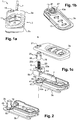
- the housing 3 is made in two parts in the form of an upper half-shell 3a forming a lid and a lower half-shell 3b forming a bottom of the housing, these two half-shells 3a, 3b being able to be assembled for example by clipping.
- a seal may be disposed between the two half-shells 3a, 3b to protect the interior of the housing 3 against the external environment, particularly against moisture or dust.
- the key 1 can also combine a mechanical key and an electronic key.
- a printed circuit board (not shown) is disposed in the housing 3.
- This board carries the remote control electronic circuits for central locking / unlocking of the vehicle doors, and a transponder (not shown) for the anti-theft system of the vehicle and a battery (not shown) for the remote control function.
- This remote control function is operated by the operator by means of actuating buttons 11 provided on the upper half-shell 3a.
- a cover 13 may be disposed in the housing 3 to conceal the electrical or electronic components of the remote control housing 3.
- the support 5 comprises two opposite ends 5a, 5b whose end 5a carries the bit 7.
- one end 7a of the bit 7 may be fitted into a complementary housing (not shown) at the end. 5a of the support 5.
- the support assembly 5 / bit 7 is held fixed for example by a pin (not shown) passing through holes 17 formed on the support 5 and the bit 7.
- the blade 7 can be fixed to the support 5 by any other appropriate means.
- the push button 19 When the push button 19 is actuated by the user, the push button 19 is driven in axial translation along the longitudinal axis A within the support 5.
- This stopping means may comprise a pin of FIG. stopping in the support 5 on which the push button 19 comes into contact at the end of travel, so that the translational movement of the push button 19 is stopped before the latter reaches the bottom wall of the support 5.
- this guide blocking means comprises at least one guide pin 25 which projects outwardly from the external surface of the pushbutton 19. It can be provided that the pushbutton 19 comprises two diametrically opposed guide pins 25 or three regularly distributed guide pins 25 for optimized translation guidance.
- each guide pin 25 cooperates with a corresponding notch 27 provided at the housing 21 on the upper half-shell 3a to guide the push button 19 in translation relative to the housing 3 along the axis A and to immobilize the push button 19 in rotation relative to the housing 3.
- the return element 23 is fixed by its second end 23b to the push button 19 thus stable in rotation ( figure 1c ) without requiring an intermediate piece between the push button 19 and the return member 23 of the deployment mechanism.
- the push button 19 has a hollow interior space 20 for housing the second end 23b of the return element 23.
- two first parallel lips 29 are formed in the bottom of the pushbutton 19 and extend towards the second end 23b of the return element 23 to receive this second end 23b.
- the second end 23b extends back inside the return element 23.
- the first lips 29 thus make it possible to block the second end 23b with respect to the push button 19 and thus to block the second end 23b in rotation relative to the upper half-shell 3a of the housing 3.
- the return element 23 is preferably fixed by its first end 23a to the support 5.
- the spring has its lower end locked in rotation on the yoke or support of the insert, inserted in a groove arranged on the bottom of the latter, and its upper end locked in rotation at the bottom of the button on its closed wall. In said rest position, it is thus prestressed in torsion.
- the support 5 may comprise a hollow pin 31 for housing the first end 23a of the return element 23 at the bottom wall 33 of the support 5.
- This pin 31 is for example connected to an inner side wall 35 of the support 5 by a radial bridge 37 and may be from material.
- the second lips 39 block the first end 23a relative to the pin 31 of the support 5 pivotally mounted relative to the housing 3, in order to allow the transmission of the restoring force of the return element 23 to the support 5.
- the support 5 is open at its bottom in a circular arc, in which the stud 15 is introduced during assembly of the support 5 on the lower half-shell 3b.
- This circular arc is centered on the pivot axis A so that during the pivoting of the support 5, the stop pin 15 circulates in this arc until the radial bridge 37 abuts against this stud stop 15, so as to block the pivoting movement of the support 5.
- the support 5 may further comprise two guide fingers (not shown) on either side of the second end 5b, which, under the effect of the actuation of the push button 19, are respectively guided by a first guide groove 43a formed in the upper half-shell 3a and by a second guide groove 43b formed in the lower half-shell 3b (see Figures 1b and 1c ).
- These guide grooves 43a, 43b have a generally semicircular shape and are each delimited by two stops 45,47.
- the push button 19 has at least one retaining projection 49 of the insert 5,7 in the rest position, and the support 5 has a flange 51.
- This flange 51 is open to allow the passage of the retaining projection 49 and has a notch 53 cooperating with the retaining projection 49, so that the retaining projection 49 engages the notch 53 in the rest position and releases the notch 53 when the push button 19 is actuated, so as to allow the pivoting of the support 5.
- the assembly comprising the support 5, the bit 7, the push button 19 and the return element 23, form a deployment module of the insert 5.7.
- This deployment module is assembled independently of the housing 3.
- the biasing member 23 is a helical torsion spring
- the rotation of the push button 19 until the holding projection 49 engages the notch 53 makes it possible to pre-constrain the spring in a simple manner. torsion.
- the deployment module thus assembled, it can be mounted in the housing 3.
- the two half-shells 3a, 3b are then fixed together.
- the blade 7 is disengaged from the recess 9 and then moves from its retracted position into the housing 3, in its extended position relative to the housing 3 in which the blade 7 can be used, realizing for example an angle of 180 °.
- This use position is reached when the guiding fingers of the support 5 are pressed against the stops 47 of the housing 3, which blocks any further movement.
- such a deployment module forms a pre-assembled unit for the key 1 to easily constrain the return element 23 during assembly and can be mounted in a simple manner in the housing 3 of the key 1 , while limiting the number of parts required for the articulation of the insert 5.7 relative to the housing 3.
Landscapes
- Lock And Its Accessories (AREA)
- Push-Button Switches (AREA)
Claims (9)
- Schlüssel, insbesondere für ein Kraftfahrzeug, welcher aufweist:- ein Gehäuse (3) mit einer oberen Halbschale (3a), die einen Deckel bildet, und einer unteren Halbschale (3b), die einen Gehäuseboden bildet,- einen Einsatz (5, 7), der bezüglich des Gehäuses (3) schwenkbar um eine Schwenkachse (A) zwischen einer Ruheposition, in welcher der Einsatz (5, 7) in das Gehäuse (3) eingeklappt ist, und einer Gebrauchsposition, in welcher der Einsatz (5, 7) bezüglich des Gehäuses (3) ausgeklappt ist, gelagert ist,- einen Mechanismus zum Ausklappen des Einsatzes (5, 7), der im Gehäuse (3) angebracht ist und umfasst:• einen Druckknopf (19), der axial in einer zugeordneten Aufnahme (21) der oberen Halbschale (3a) aufgenommen ist und aus der oberen Halbschale (3a) herausragt, um von einem Benutzer betätigt zu werden, und• ein elastisches Rückstellelement (23) für den Einsatz (5, 7), von dem ein erstes Ende (23a) mit dem Einsatz (5, 7) verbunden ist, um den Einsatz (5, 7) im Sinne einer Schwenkung in Richtung der Gebrauchsposition zu beaufschlagen, wenn der Druckknopf (19) betätigt wird,wobei der Druckknopf (19) ein Mittel zur Verdrehsicherung des Druckknopfes (19) in Bezug auf das Gehäuse aufweist, das als Führung des Druckknopfes (19) bei axialer Translation dient, wobei das Rückstellelement (23) an dem Druckknopf (19) mittels eines zweiten Endes (23b) befestigt ist, wobei der Einsatz einen Schlüsselbart (7) und einen mit dem Schlüsselbart (7) fest verbundenen Schlüsselbarthalter (5), der schwenkbar bezüglich des Gehäuses (3) gelagert ist, aufweist, wobei das erste Ende (23a) des Rückstellelements (23) an dem Schlüsselbarthalter (5) befestigt ist, derart, dass das Rückstellelement (23) den Halter (5) im Sinne einer Schwenkung bezüglich des Gehäuses (3) beaufschlagt, um den Schlüsselbart (7) auszuklappen, wenn der Druckknopf (19) betätigt wird, wobei der Schlüsselbarthalter (5) einen hohlen Zapfen (31) aufweist, um das erste Ende (23a) des Rückstellelements (23) an der Wand des Bodens (33) des Schlüsselbarthalters (5) aufzunehmen, wobei der Zapfen (31) mit einer inneren Seitenwand (35) des Schlüsselbarthalters (5) durch eine radiale Brücke (37) verbunden ist, wobei die untere Halbschale (3b) des Gehäuses (3) einen Absatz (9) aufweist, um den Schlüsselbarthalter (5) in der Ruheposition aufzunehmen, wobei eine Öffnung an der Innenwand der unteren Halbschale (3b) im Bereich des Absatzes (9) für die Einpassung des Zapfens (31) vorgesehen ist, wobei der Schlüssel ein Mittel zur Arretierung des Druckknopfes (19) gegen Translation aufweist, das wenigstens teilweise in dem Halter (5) angeordnet ist, wobei dieses Arretiermittel einen an die untere Halbschale (3b) angeformten Anschlagklotz (15) aufweist, der in eine am Halter (5) vorgesehene Aussparung eingeführt wird, die an ihrem Boden entlang eines auf der Schwenkachse (A) zentrierten Kreisbogens offen ist, derart, dass bei der Schwenkung des Halters (5) der Anschlagklotz (15) sich in dem Kreisbogen bewegt, bis die radiale Brücke (37) an dem Anschlagklotz (15) zur Anlage kommt, so dass die Schwenkbewegung des Halters (5) blockiert wird.
- Schlüssel nach Anspruch 1, dadurch gekennzeichnet, dass der Druckknopf (19) und das Mittel zur Verdrehsicherung, das als Führung dient, aus einem Stück hergestellt sind.
- Schlüssel nach einem der Ansprüche 1 oder 2, dadurch gekennzeichnet, dass das Mittel zur Verdrehsicherung, das als Führung dient, wenigstens einen Führungsvorsprung (25) des Druckknopfes (19) umfasst, der mit einem entsprechenden Einschnitt (27) der Aufnahme (21) der oberen Halbschale (3a) zusammenwirkt.
- Schlüssel nach Anspruch 3, dadurch gekennzeichnet, dass das Mittel zur Verdrehsicherung, das als Führung dient, drei Führungsvorsprünge (25) des Druckknopfes (19) umfasst, die gleichmäßig verteilt sind.
- Schlüssel nach einem der Ansprüche 1 bis 4, dadurch gekennzeichnet, dass der Druckknopf (19) einen inneren Hohlraum (20) aufweist, in dessen Innerem das zweite Ende (23b) des Rückstellelements (23) aufgenommen ist.
- Schlüssel nach Anspruch 5, dadurch gekennzeichnet, dass zwei parallele erste Lippen (29) im Boden des Druckknopfes (19) ausgebildet sind und das zweite Ende (23b) des Rückstellelements (23) aufnehmen.
- Schlüssel nach einem der Ansprüche 1 bis 6, dadurch gekennzeichnet, dass zwei parallele zweite Lippen (39) in dem Zapfen (31) ausgebildet sind und das erste Ende (23a) des Rückstellelements (23) aufnehmen.
- Schlüssel nach einem der Ansprüche 1 bis 7, dadurch gekennzeichnet, dass- der Druckknopf (19) wenigstens einen Haltevorsprung (49) für den Einsatz (5, 7) in der Ruheposition aufweist, dadurch, dass- der Halter (5) einen Kragen (51) aufweist, der für die Hindurchbewegung des Haltevorsprungs (49) offen ist, und dadurch, dass- der Kragen (51) eine Einkerbung (53) aufweist, die mit dem Haltevorsprung (49) zusammenwirkt,
derart, dass der Haltevorsprung (49) in der Ruheposition mit der Einkerbung (53) in Eingriff steht, und dass der Haltevorsprung (49) die Einkerbung (53) freigibt, wenn der Druckknopf (19) betätigt wird, um so die Schwenkung des Halters (5) zu ermöglichen. - Schlüssel nach einem der Ansprüche 1 bis 8, dadurch gekennzeichnet, dass das Rückstellelement (23) in der Form einer Torsionsschraubenfeder hergestellt ist.
Applications Claiming Priority (3)
| Application Number | Priority Date | Filing Date | Title |
|---|---|---|---|
| FR0855835A FR2935419B1 (fr) | 2008-09-01 | 2008-09-01 | Dispositif de telecommande a cle escamotable, en particulier de vehicule automobile. |
| FR0806917A FR2935418B1 (fr) | 2008-09-01 | 2008-12-10 | Cle a insert escamotable et module de deploiement correspondant. |
| PCT/EP2009/061170 WO2010023294A1 (fr) | 2008-09-01 | 2009-08-28 | Cle a insert escamotable et module de deploiement correspondant |
Publications (2)
| Publication Number | Publication Date |
|---|---|
| EP2331777A1 EP2331777A1 (de) | 2011-06-15 |
| EP2331777B1 true EP2331777B1 (de) | 2019-07-03 |
Family
ID=40467150
Family Applications (2)
| Application Number | Title | Priority Date | Filing Date |
|---|---|---|---|
| EP09809347.9A Not-in-force EP2331776B1 (de) | 2008-09-01 | 2009-08-28 | Fernbedienung mit klappschlüssel, im besonderen für ein auto |
| EP09809348.7A Not-in-force EP2331777B1 (de) | 2008-09-01 | 2009-08-28 | Schlüssel mit klappeinsatz |
Family Applications Before (1)
| Application Number | Title | Priority Date | Filing Date |
|---|---|---|---|
| EP09809347.9A Not-in-force EP2331776B1 (de) | 2008-09-01 | 2009-08-28 | Fernbedienung mit klappschlüssel, im besonderen für ein auto |
Country Status (6)
| Country | Link |
|---|---|
| US (2) | US8763434B2 (de) |
| EP (2) | EP2331776B1 (de) |
| JP (2) | JP5650645B2 (de) |
| CN (2) | CN102216546B (de) |
| FR (2) | FR2935419B1 (de) |
| WO (2) | WO2010023294A1 (de) |
Families Citing this family (29)
| Publication number | Priority date | Publication date | Assignee | Title |
|---|---|---|---|---|
| FR2922572B1 (fr) * | 2007-10-19 | 2013-02-01 | Johnson Controls Tech Co | Cle pivotante a blocage en position renforce, pour l'actionnement d'une serrure. |
| EP2342404B1 (de) * | 2008-11-05 | 2016-01-27 | Johnson Controls Technology Company | Mechanisches modul für einen fahrzeugschlüssel und herstellungsverfahren dafür |
| FR2952956B1 (fr) * | 2009-11-20 | 2011-12-09 | Valeo Securite Habitacle | Cle a insert escamotable a resistance mecanique amelioree |
| FR2967188B1 (fr) | 2010-11-05 | 2013-05-31 | Valeo Securite Habitacle | Cle a insert escamotable et module de deploiement d'insert associe |
| EP2460956B2 (de) * | 2010-12-06 | 2022-07-27 | Valeo Climatizacion S.A. | Flip-Key für ein Automobil mit verstärktem Widerstand gegen Kräfte, die auf einen Einsatz eines solchen Flip-Keys ausgeübt werden |
| DE102010061333A1 (de) * | 2010-12-17 | 2012-06-21 | Huf Hülsbeck & Fürst Gmbh & Co. Kg | Kombinierter mechanischer und elektronischer Schlüssel für ein Kraftfahrzeug mit einem Mitnehmer, der als Flügel wirkt |
| FR2977269B1 (fr) * | 2011-06-29 | 2015-10-09 | Valeo Securite Habitacle | Cle a insert escamotable et module de deploiement correspondant. |
| FR2984943B1 (fr) | 2011-12-23 | 2016-11-25 | Valeo Securite Habitacle | Cle a insert escamotable et module de deploiement correspondant |
| FR2984944B1 (fr) * | 2011-12-23 | 2014-04-25 | Valeo Securite Habitacle | Cle a insert escamotable et module de deploiement correspondant |
| FR2990977B1 (fr) * | 2012-05-25 | 2014-07-11 | Valeo Securite Habitacle | Procede d'obtention d'un bouton poussoir de cle a insert escamotable |
| FR2992673B1 (fr) | 2012-06-29 | 2015-02-06 | Valeo Securite Habitacle | Cle a insert escamotable |
| KR101384657B1 (ko) | 2012-10-10 | 2014-04-14 | 현대모비스 주식회사 | 차량용 폴딩키 |
| JP6069748B2 (ja) * | 2012-11-06 | 2017-02-01 | 美和ロック株式会社 | 携帯型キー |
| FR3000124B1 (fr) * | 2012-12-21 | 2015-03-06 | Valeo Securite Habitacle | Cle a insert escamotable avec jeu limite |
| JP6182337B2 (ja) * | 2013-03-27 | 2017-08-16 | 美和ロック株式会社 | 携帯型キー |
| FR3007354B1 (fr) * | 2013-06-19 | 2015-06-05 | Shin France U | Antivol de direction pour vehicule automobile a supercondamnation et procede de montage associe |
| EP3021665B1 (de) | 2013-07-16 | 2019-09-11 | University of Florida Research Foundation, Inc. | Verfahren und vorrichtung zur anhaltenden freisetzung von wirkstoffen |
| JP6095530B2 (ja) * | 2013-09-09 | 2017-03-15 | アルプス電気株式会社 | 携帯用装置の組立方法 |
| TWM480579U (zh) * | 2014-02-26 | 2014-06-21 | Shun-Fu Chen | 可隱藏鎖芯之鑰匙部構造 |
| JP2015161136A (ja) * | 2014-02-28 | 2015-09-07 | Ykk Ap株式会社 | キーヘッドカバー |
| JP2016089336A (ja) * | 2014-10-29 | 2016-05-23 | 株式会社ホンダロック | キーユニット |
| DE102016105161A1 (de) * | 2016-03-21 | 2017-09-21 | Huf Hülsbeck & Fürst Gmbh & Co. Kg | Schlüsselschaft für einen Kraftfahrzeugschlüssel |
| CN107366476B (zh) * | 2016-05-13 | 2019-05-07 | 上海海拉电子有限公司 | 汽车备用钥匙的开合组件及其安装方法 |
| US9984837B2 (en) * | 2016-07-28 | 2018-05-29 | Safety Technology International, Inc. | Multi configurable alarm station incorporating a push button assembly and assembly kit therefor |
| CN108071268B (zh) * | 2016-11-07 | 2019-12-13 | 法雷奥汽车内部控制(深圳)有限公司 | 用于机动车辆的钥匙组件 |
| CN108060833B (zh) * | 2016-11-07 | 2019-11-05 | 法雷奥汽车内部控制(深圳)有限公司 | 用于机动车辆的钥匙组件 |
| CN108341328B (zh) * | 2018-02-02 | 2019-07-26 | 浙江大学 | 一种直径可调节的起吊抱箍装置 |
| JP1664625S (de) * | 2019-03-05 | 2020-07-27 | ||
| CN111295092B (zh) * | 2020-04-16 | 2024-12-13 | 昆山铭世特精密机械有限公司 | 一种带压爪的载具 |
Family Cites Families (19)
| Publication number | Priority date | Publication date | Assignee | Title |
|---|---|---|---|---|
| US2822684A (en) * | 1956-07-02 | 1958-02-11 | William J Ray | Key holder |
| DE3769923D1 (de) * | 1986-10-20 | 1991-06-13 | Siemens Ag | Geraet zum fernsteuern einer mit einem empfaenger ausgeruesteten schliessanlage, insbesondere fuer kraftfahrzeuge. |
| US5943889A (en) * | 1998-03-05 | 1999-08-31 | Chiu; Kuang-Yen | Collapsible key assembly |
| DE19952247C1 (de) * | 1999-10-29 | 2001-04-05 | Valeo Gmbh & Co Schliessyst Kg | Elektronischer Flachschlüssel |
| DE19962976C1 (de) * | 1999-12-24 | 2001-09-20 | Huf Huelsbeck & Fuerst Gmbh | Kombinierter mechanischer und elektronischer Schlüssel, insbesondere für an Fahrzeugen befindliche Schlösser |
| DE19962975A1 (de) * | 1999-12-24 | 2001-07-05 | Huf Huelsbeck & Fuerst Gmbh | Kombinierter mechanischer und elektronischer Schlüssel, insbesondere für an Fahrzeugen befindliche Schlösser |
| US6389857B1 (en) * | 2000-03-31 | 2002-05-21 | Master Lock Company | Push-button steering wheel lock |
| FR2861114B1 (fr) * | 2003-10-20 | 2006-01-06 | Johnson Contr Automotive Elect | Cle d'actionnement d'une serrure |
| US7055352B2 (en) * | 2003-11-19 | 2006-06-06 | Meyerson David W | Apparatus for storing and positioning keys |
| ES2277477B1 (es) * | 2004-03-17 | 2008-05-16 | Carlos Brion Camean | Llavero. |
| EP1609931B1 (de) * | 2004-06-23 | 2006-11-02 | Delphi Technologies, Inc. | Fernsteuervorrichtung mit einklappbarem Schlüssel, insbesondere für Kraftfahrzeug |
| US7127922B2 (en) * | 2004-07-21 | 2006-10-31 | Saysamon Khounsombath | Key unit holder |
| JP2007085074A (ja) * | 2005-09-22 | 2007-04-05 | Honda Lock Mfg Co Ltd | イモビライザー用キー |
| US7370501B2 (en) * | 2006-03-22 | 2008-05-13 | Kabushiki Kaisha Honda Lock | Key unit |
| DE102006036503B4 (de) * | 2006-08-04 | 2015-09-17 | Hella Kgaa Hueck & Co. | Kombinierter mechanischer und elektronischer Schlüssel |
| FR2915759B1 (fr) * | 2007-05-03 | 2009-07-03 | Johnson Controls Tech Co | Cle de serrure retractable a pivot renforce |
| FR2919327A1 (fr) * | 2007-07-27 | 2009-01-30 | Johnson Controls Tech Co | Cle d'actionnement d'une serrure a resistance aux chocs amelioree |
| US8225633B2 (en) * | 2008-03-03 | 2012-07-24 | Lear Corporation | Rotation mechanism for key blade |
| FR2952956B1 (fr) * | 2009-11-20 | 2011-12-09 | Valeo Securite Habitacle | Cle a insert escamotable a resistance mecanique amelioree |
-
2008
- 2008-09-01 FR FR0855835A patent/FR2935419B1/fr not_active Expired - Fee Related
- 2008-12-10 FR FR0806917A patent/FR2935418B1/fr active Active
-
2009
- 2009-08-28 EP EP09809347.9A patent/EP2331776B1/de not_active Not-in-force
- 2009-08-28 CN CN200980133790.8A patent/CN102216546B/zh not_active Expired - Fee Related
- 2009-08-28 CN CN200980133789.5A patent/CN102232134B/zh not_active Expired - Fee Related
- 2009-08-28 US US13/060,743 patent/US8763434B2/en active Active
- 2009-08-28 EP EP09809348.7A patent/EP2331777B1/de not_active Not-in-force
- 2009-08-28 JP JP2011524400A patent/JP5650645B2/ja not_active Expired - Fee Related
- 2009-08-28 WO PCT/EP2009/061170 patent/WO2010023294A1/fr not_active Ceased
- 2009-08-28 WO PCT/EP2009/061168 patent/WO2010023293A1/fr not_active Ceased
- 2009-08-28 US US13/060,735 patent/US8770001B2/en not_active Expired - Fee Related
- 2009-08-28 JP JP2011524401A patent/JP5739331B2/ja active Active
Non-Patent Citations (1)
| Title |
|---|
| None * |
Also Published As
| Publication number | Publication date |
|---|---|
| WO2010023294A1 (fr) | 2010-03-04 |
| CN102216546B (zh) | 2016-07-06 |
| US20110179838A1 (en) | 2011-07-28 |
| FR2935418B1 (fr) | 2010-10-15 |
| JP5650645B2 (ja) | 2015-01-07 |
| FR2935419B1 (fr) | 2010-10-15 |
| CN102232134B (zh) | 2016-08-10 |
| JP5739331B2 (ja) | 2015-06-24 |
| US20110259064A1 (en) | 2011-10-27 |
| EP2331777A1 (de) | 2011-06-15 |
| JP2012501392A (ja) | 2012-01-19 |
| CN102216546A (zh) | 2011-10-12 |
| WO2010023293A1 (fr) | 2010-03-04 |
| EP2331776A1 (de) | 2011-06-15 |
| CN102232134A (zh) | 2011-11-02 |
| FR2935419A1 (fr) | 2010-03-05 |
| US8763434B2 (en) | 2014-07-01 |
| JP2012501393A (ja) | 2012-01-19 |
| EP2331776B1 (de) | 2019-03-27 |
| FR2935418A1 (fr) | 2010-03-05 |
| US8770001B2 (en) | 2014-07-08 |
Similar Documents
| Publication | Publication Date | Title |
|---|---|---|
| EP2501882B1 (de) | Schlüssel mit versenkbarem einsatz und mit erhöhter mechanischer festigkeit | |
| EP2331777A1 (de) | Schlüssel mit klappeinsatz und entsprechendes ausziehmodul | |
| EP2795025B1 (de) | Schlüssel mit einziehbarem einsatz und entsprechendes auslösungsmodul | |
| EP0088699B1 (de) | Schlüsselhalter mit einem in ein Gehäuse einklappbaren Schlüssel | |
| EP1956619A1 (de) | Verriegelungsschalter | |
| EP0985788B1 (de) | Schlüssel, insbesondere für Kraftfahrzeuge, mit Schlüsselkopf bestehend aus einem Fernbedienungsgehäuse mit herausklappbarem Einsatz und Verfahren zu seiner Herstellung | |
| EP1291479B1 (de) | Schloss mit Universalaufstellung | |
| EP2635753B1 (de) | Schlüssel mit einziehbarem einsatz | |
| FR2867499A1 (fr) | Verrou de couverture de piscine | |
| FR3107295A1 (fr) | Dispositif de verrouillage pour une pièce mobile d’un véhicule | |
| WO2011061276A1 (fr) | Cle a insert escamotable | |
| EP2935729B1 (de) | Schlüssel mit herausklappbarem einsatz mit spielraumeinschränkung | |
| WO2013093094A1 (fr) | Clé à insert escamotable et module de déploiement correspondant | |
| EP2071105A1 (de) | Schlüssel mit versenkbarem Einsatz | |
| EP1063374B1 (de) | Schlüssel, insbesondere für Kraftfahrzeuge, mit einem Schlüsselbart und einem Griffteil | |
| FR2936635A1 (fr) | Module d'identification pour vehicule automobile. | |
| FR3064660A1 (fr) | Dispositif de verrouillage pour couvercle de compartiment de rangement, compartiment de rangement associe et vehicule associe | |
| WO2013001051A1 (fr) | Cle a insert escamotable et module de deploiement correspondant | |
| WO2014001500A1 (fr) | Clé a insert escamotable | |
| EP2172375A1 (de) | Mobiles Steuerungsmodul | |
| FR3069217A1 (fr) | Boite a gants | |
| FR3138824A1 (fr) | Dispositif de verrouillage pour ouvrant d’un véhicule | |
| FR2769938A1 (fr) | Serrure electrique commandee par un interrupteur susceptible d'etre inhibe | |
| FR2984947A3 (fr) | Charniere a interrupteur de securite multiple integre | |
| FR2860403A1 (fr) | Dispositif de verrouillage de siege |
Legal Events
| Date | Code | Title | Description |
|---|---|---|---|
| PUAI | Public reference made under article 153(3) epc to a published international application that has entered the european phase |
Free format text: ORIGINAL CODE: 0009012 |
|
| 17P | Request for examination filed |
Effective date: 20110401 |
|
| AK | Designated contracting states |
Kind code of ref document: A1 Designated state(s): AT BE BG CH CY CZ DE DK EE ES FI FR GB GR HR HU IE IS IT LI LT LU LV MC MK MT NL NO PL PT RO SE SI SK SM TR |
|
| AX | Request for extension of the european patent |
Extension state: AL BA RS |
|
| DAX | Request for extension of the european patent (deleted) | ||
| STAA | Information on the status of an ep patent application or granted ep patent |
Free format text: STATUS: EXAMINATION IS IN PROGRESS |
|
| 17Q | First examination report despatched |
Effective date: 20170404 |
|
| GRAP | Despatch of communication of intention to grant a patent |
Free format text: ORIGINAL CODE: EPIDOSNIGR1 |
|
| STAA | Information on the status of an ep patent application or granted ep patent |
Free format text: STATUS: GRANT OF PATENT IS INTENDED |
|
| INTG | Intention to grant announced |
Effective date: 20190319 |
|
| GRAS | Grant fee paid |
Free format text: ORIGINAL CODE: EPIDOSNIGR3 |
|
| GRAA | (expected) grant |
Free format text: ORIGINAL CODE: 0009210 |
|
| STAA | Information on the status of an ep patent application or granted ep patent |
Free format text: STATUS: THE PATENT HAS BEEN GRANTED |
|
| AK | Designated contracting states |
Kind code of ref document: B1 Designated state(s): AT BE BG CH CY CZ DE DK EE ES FI FR GB GR HR HU IE IS IT LI LT LU LV MC MK MT NL NO PL PT RO SE SI SK SM TR |
|
| REG | Reference to a national code |
Ref country code: GB Ref legal event code: FG4D Free format text: NOT ENGLISH |
|
| REG | Reference to a national code |
Ref country code: CH Ref legal event code: EP Ref country code: AT Ref legal event code: REF Ref document number: 1151182 Country of ref document: AT Kind code of ref document: T Effective date: 20190715 |
|
| REG | Reference to a national code |
Ref country code: IE Ref legal event code: FG4D Free format text: LANGUAGE OF EP DOCUMENT: FRENCH |
|
| REG | Reference to a national code |
Ref country code: DE Ref legal event code: R096 Ref document number: 602009059019 Country of ref document: DE |
|
| REG | Reference to a national code |
Ref country code: NL Ref legal event code: MP Effective date: 20190703 |
|
| REG | Reference to a national code |
Ref country code: LT Ref legal event code: MG4D |
|
| REG | Reference to a national code |
Ref country code: AT Ref legal event code: MK05 Ref document number: 1151182 Country of ref document: AT Kind code of ref document: T Effective date: 20190703 |
|
| PG25 | Lapsed in a contracting state [announced via postgrant information from national office to epo] |
Ref country code: FI Free format text: LAPSE BECAUSE OF FAILURE TO SUBMIT A TRANSLATION OF THE DESCRIPTION OR TO PAY THE FEE WITHIN THE PRESCRIBED TIME-LIMIT Effective date: 20190703 Ref country code: CZ Free format text: LAPSE BECAUSE OF FAILURE TO SUBMIT A TRANSLATION OF THE DESCRIPTION OR TO PAY THE FEE WITHIN THE PRESCRIBED TIME-LIMIT Effective date: 20190703 Ref country code: NO Free format text: LAPSE BECAUSE OF FAILURE TO SUBMIT A TRANSLATION OF THE DESCRIPTION OR TO PAY THE FEE WITHIN THE PRESCRIBED TIME-LIMIT Effective date: 20191003 Ref country code: AT Free format text: LAPSE BECAUSE OF FAILURE TO SUBMIT A TRANSLATION OF THE DESCRIPTION OR TO PAY THE FEE WITHIN THE PRESCRIBED TIME-LIMIT Effective date: 20190703 Ref country code: PT Free format text: LAPSE BECAUSE OF FAILURE TO SUBMIT A TRANSLATION OF THE DESCRIPTION OR TO PAY THE FEE WITHIN THE PRESCRIBED TIME-LIMIT Effective date: 20191104 Ref country code: NL Free format text: LAPSE BECAUSE OF FAILURE TO SUBMIT A TRANSLATION OF THE DESCRIPTION OR TO PAY THE FEE WITHIN THE PRESCRIBED TIME-LIMIT Effective date: 20190703 Ref country code: SE Free format text: LAPSE BECAUSE OF FAILURE TO SUBMIT A TRANSLATION OF THE DESCRIPTION OR TO PAY THE FEE WITHIN THE PRESCRIBED TIME-LIMIT Effective date: 20190703 Ref country code: BG Free format text: LAPSE BECAUSE OF FAILURE TO SUBMIT A TRANSLATION OF THE DESCRIPTION OR TO PAY THE FEE WITHIN THE PRESCRIBED TIME-LIMIT Effective date: 20191003 Ref country code: LT Free format text: LAPSE BECAUSE OF FAILURE TO SUBMIT A TRANSLATION OF THE DESCRIPTION OR TO PAY THE FEE WITHIN THE PRESCRIBED TIME-LIMIT Effective date: 20190703 Ref country code: HR Free format text: LAPSE BECAUSE OF FAILURE TO SUBMIT A TRANSLATION OF THE DESCRIPTION OR TO PAY THE FEE WITHIN THE PRESCRIBED TIME-LIMIT Effective date: 20190703 |
|
| PG25 | Lapsed in a contracting state [announced via postgrant information from national office to epo] |
Ref country code: GR Free format text: LAPSE BECAUSE OF FAILURE TO SUBMIT A TRANSLATION OF THE DESCRIPTION OR TO PAY THE FEE WITHIN THE PRESCRIBED TIME-LIMIT Effective date: 20191004 Ref country code: LV Free format text: LAPSE BECAUSE OF FAILURE TO SUBMIT A TRANSLATION OF THE DESCRIPTION OR TO PAY THE FEE WITHIN THE PRESCRIBED TIME-LIMIT Effective date: 20190703 Ref country code: IS Free format text: LAPSE BECAUSE OF FAILURE TO SUBMIT A TRANSLATION OF THE DESCRIPTION OR TO PAY THE FEE WITHIN THE PRESCRIBED TIME-LIMIT Effective date: 20191103 Ref country code: ES Free format text: LAPSE BECAUSE OF FAILURE TO SUBMIT A TRANSLATION OF THE DESCRIPTION OR TO PAY THE FEE WITHIN THE PRESCRIBED TIME-LIMIT Effective date: 20190703 |
|
| PG25 | Lapsed in a contracting state [announced via postgrant information from national office to epo] |
Ref country code: TR Free format text: LAPSE BECAUSE OF FAILURE TO SUBMIT A TRANSLATION OF THE DESCRIPTION OR TO PAY THE FEE WITHIN THE PRESCRIBED TIME-LIMIT Effective date: 20190703 |
|
| PG25 | Lapsed in a contracting state [announced via postgrant information from national office to epo] |
Ref country code: PL Free format text: LAPSE BECAUSE OF FAILURE TO SUBMIT A TRANSLATION OF THE DESCRIPTION OR TO PAY THE FEE WITHIN THE PRESCRIBED TIME-LIMIT Effective date: 20190703 Ref country code: DK Free format text: LAPSE BECAUSE OF FAILURE TO SUBMIT A TRANSLATION OF THE DESCRIPTION OR TO PAY THE FEE WITHIN THE PRESCRIBED TIME-LIMIT Effective date: 20190703 Ref country code: RO Free format text: LAPSE BECAUSE OF FAILURE TO SUBMIT A TRANSLATION OF THE DESCRIPTION OR TO PAY THE FEE WITHIN THE PRESCRIBED TIME-LIMIT Effective date: 20190703 Ref country code: IT Free format text: LAPSE BECAUSE OF FAILURE TO SUBMIT A TRANSLATION OF THE DESCRIPTION OR TO PAY THE FEE WITHIN THE PRESCRIBED TIME-LIMIT Effective date: 20190703 Ref country code: EE Free format text: LAPSE BECAUSE OF FAILURE TO SUBMIT A TRANSLATION OF THE DESCRIPTION OR TO PAY THE FEE WITHIN THE PRESCRIBED TIME-LIMIT Effective date: 20190703 |
|
| PG25 | Lapsed in a contracting state [announced via postgrant information from national office to epo] |
Ref country code: SK Free format text: LAPSE BECAUSE OF FAILURE TO SUBMIT A TRANSLATION OF THE DESCRIPTION OR TO PAY THE FEE WITHIN THE PRESCRIBED TIME-LIMIT Effective date: 20190703 Ref country code: IS Free format text: LAPSE BECAUSE OF FAILURE TO SUBMIT A TRANSLATION OF THE DESCRIPTION OR TO PAY THE FEE WITHIN THE PRESCRIBED TIME-LIMIT Effective date: 20200224 Ref country code: LI Free format text: LAPSE BECAUSE OF NON-PAYMENT OF DUE FEES Effective date: 20190831 Ref country code: SM Free format text: LAPSE BECAUSE OF FAILURE TO SUBMIT A TRANSLATION OF THE DESCRIPTION OR TO PAY THE FEE WITHIN THE PRESCRIBED TIME-LIMIT Effective date: 20190703 Ref country code: LU Free format text: LAPSE BECAUSE OF NON-PAYMENT OF DUE FEES Effective date: 20190828 Ref country code: CH Free format text: LAPSE BECAUSE OF NON-PAYMENT OF DUE FEES Effective date: 20190831 Ref country code: MC Free format text: LAPSE BECAUSE OF FAILURE TO SUBMIT A TRANSLATION OF THE DESCRIPTION OR TO PAY THE FEE WITHIN THE PRESCRIBED TIME-LIMIT Effective date: 20190703 |
|
| REG | Reference to a national code |
Ref country code: BE Ref legal event code: MM Effective date: 20190831 |
|
| REG | Reference to a national code |
Ref country code: DE Ref legal event code: R097 Ref document number: 602009059019 Country of ref document: DE |
|
| PLBE | No opposition filed within time limit |
Free format text: ORIGINAL CODE: 0009261 |
|
| STAA | Information on the status of an ep patent application or granted ep patent |
Free format text: STATUS: NO OPPOSITION FILED WITHIN TIME LIMIT |
|
| PG2D | Information on lapse in contracting state deleted |
Ref country code: IS |
|
| PG25 | Lapsed in a contracting state [announced via postgrant information from national office to epo] |
Ref country code: IE Free format text: LAPSE BECAUSE OF NON-PAYMENT OF DUE FEES Effective date: 20190828 |
|
| 26N | No opposition filed |
Effective date: 20200603 |
|
| PG25 | Lapsed in a contracting state [announced via postgrant information from national office to epo] |
Ref country code: SI Free format text: LAPSE BECAUSE OF FAILURE TO SUBMIT A TRANSLATION OF THE DESCRIPTION OR TO PAY THE FEE WITHIN THE PRESCRIBED TIME-LIMIT Effective date: 20190703 Ref country code: BE Free format text: LAPSE BECAUSE OF NON-PAYMENT OF DUE FEES Effective date: 20190831 |
|
| GBPC | Gb: european patent ceased through non-payment of renewal fee |
Effective date: 20191003 |
|
| PG25 | Lapsed in a contracting state [announced via postgrant information from national office to epo] |
Ref country code: GB Free format text: LAPSE BECAUSE OF NON-PAYMENT OF DUE FEES Effective date: 20191003 |
|
| PG25 | Lapsed in a contracting state [announced via postgrant information from national office to epo] |
Ref country code: CY Free format text: LAPSE BECAUSE OF FAILURE TO SUBMIT A TRANSLATION OF THE DESCRIPTION OR TO PAY THE FEE WITHIN THE PRESCRIBED TIME-LIMIT Effective date: 20190703 |
|
| PG25 | Lapsed in a contracting state [announced via postgrant information from national office to epo] |
Ref country code: HU Free format text: LAPSE BECAUSE OF FAILURE TO SUBMIT A TRANSLATION OF THE DESCRIPTION OR TO PAY THE FEE WITHIN THE PRESCRIBED TIME-LIMIT; INVALID AB INITIO Effective date: 20090828 Ref country code: MT Free format text: LAPSE BECAUSE OF FAILURE TO SUBMIT A TRANSLATION OF THE DESCRIPTION OR TO PAY THE FEE WITHIN THE PRESCRIBED TIME-LIMIT Effective date: 20190703 |
|
| PG25 | Lapsed in a contracting state [announced via postgrant information from national office to epo] |
Ref country code: MK Free format text: LAPSE BECAUSE OF FAILURE TO SUBMIT A TRANSLATION OF THE DESCRIPTION OR TO PAY THE FEE WITHIN THE PRESCRIBED TIME-LIMIT Effective date: 20190703 |
|
| P01 | Opt-out of the competence of the unified patent court (upc) registered |
Effective date: 20230528 |
|
| PGFP | Annual fee paid to national office [announced via postgrant information from national office to epo] |
Ref country code: FR Payment date: 20230828 Year of fee payment: 15 Ref country code: DE Payment date: 20230808 Year of fee payment: 15 |
|
| REG | Reference to a national code |
Ref country code: DE Ref legal event code: R119 Ref document number: 602009059019 Country of ref document: DE |
|
| PG25 | Lapsed in a contracting state [announced via postgrant information from national office to epo] |
Ref country code: DE Free format text: LAPSE BECAUSE OF NON-PAYMENT OF DUE FEES Effective date: 20250301 |
|
| PG25 | Lapsed in a contracting state [announced via postgrant information from national office to epo] |
Ref country code: FR Free format text: LAPSE BECAUSE OF NON-PAYMENT OF DUE FEES Effective date: 20240831 |