EP2331829B1 - Überschall-ausstosspaket - Google Patents
Überschall-ausstosspaket Download PDFInfo
- Publication number
- EP2331829B1 EP2331829B1 EP09813517.1A EP09813517A EP2331829B1 EP 2331829 B1 EP2331829 B1 EP 2331829B1 EP 09813517 A EP09813517 A EP 09813517A EP 2331829 B1 EP2331829 B1 EP 2331829B1
- Authority
- EP
- European Patent Office
- Prior art keywords
- ejector
- supersonic
- bore
- supersonic ejector
- tandem
- Prior art date
- Legal status (The legal status is an assumption and is not a legal conclusion. Google has not performed a legal analysis and makes no representation as to the accuracy of the status listed.)
- Not-in-force
Links
- 230000000712 assembly Effects 0.000 claims description 11
- 238000000429 assembly Methods 0.000 claims description 11
- 238000004891 communication Methods 0.000 claims description 7
- 239000000463 material Substances 0.000 claims description 7
- 239000007787 solid Substances 0.000 claims description 2
- 239000010725 compressor oil Substances 0.000 claims 1
- 239000007789 gas Substances 0.000 description 57
- 229910052751 metal Inorganic materials 0.000 description 16
- 239000002184 metal Substances 0.000 description 15
- 239000000446 fuel Substances 0.000 description 6
- XEEYBQQBJWHFJM-UHFFFAOYSA-N Iron Chemical compound [Fe] XEEYBQQBJWHFJM-UHFFFAOYSA-N 0.000 description 4
- 239000000956 alloy Substances 0.000 description 4
- 238000004806 packaging method and process Methods 0.000 description 4
- 229910045601 alloy Inorganic materials 0.000 description 3
- 238000004519 manufacturing process Methods 0.000 description 3
- 229910001092 metal group alloy Inorganic materials 0.000 description 3
- 239000007769 metal material Substances 0.000 description 3
- 238000000034 method Methods 0.000 description 3
- 238000012545 processing Methods 0.000 description 3
- 229910000831 Steel Inorganic materials 0.000 description 2
- RTAQQCXQSZGOHL-UHFFFAOYSA-N Titanium Chemical compound [Ti] RTAQQCXQSZGOHL-UHFFFAOYSA-N 0.000 description 2
- 230000008901 benefit Effects 0.000 description 2
- 230000007423 decrease Effects 0.000 description 2
- 238000005516 engineering process Methods 0.000 description 2
- 229910052742 iron Inorganic materials 0.000 description 2
- 150000002739 metals Chemical class 0.000 description 2
- VNWKTOKETHGBQD-UHFFFAOYSA-N methane Chemical compound C VNWKTOKETHGBQD-UHFFFAOYSA-N 0.000 description 2
- 239000000203 mixture Substances 0.000 description 2
- 230000008569 process Effects 0.000 description 2
- 239000010959 steel Substances 0.000 description 2
- 239000000126 substance Substances 0.000 description 2
- 229910052719 titanium Inorganic materials 0.000 description 2
- 239000010936 titanium Substances 0.000 description 2
- 229910002065 alloy metal Inorganic materials 0.000 description 1
- 230000004075 alteration Effects 0.000 description 1
- 229910052782 aluminium Inorganic materials 0.000 description 1
- XAGFODPZIPBFFR-UHFFFAOYSA-N aluminium Chemical compound [Al] XAGFODPZIPBFFR-UHFFFAOYSA-N 0.000 description 1
- 230000015572 biosynthetic process Effects 0.000 description 1
- 239000000919 ceramic Substances 0.000 description 1
- 238000010276 construction Methods 0.000 description 1
- 238000005260 corrosion Methods 0.000 description 1
- 230000007797 corrosion Effects 0.000 description 1
- 238000013461 design Methods 0.000 description 1
- 238000001914 filtration Methods 0.000 description 1
- 239000012530 fluid Substances 0.000 description 1
- 230000008014 freezing Effects 0.000 description 1
- 238000007710 freezing Methods 0.000 description 1
- 238000012423 maintenance Methods 0.000 description 1
- 230000007246 mechanism Effects 0.000 description 1
- 239000003345 natural gas Substances 0.000 description 1
- 230000009257 reactivity Effects 0.000 description 1
- 230000009467 reduction Effects 0.000 description 1
- 230000001105 regulatory effect Effects 0.000 description 1
- 239000002904 solvent Substances 0.000 description 1
- 238000006467 substitution reaction Methods 0.000 description 1
- XLYOFNOQVPJJNP-UHFFFAOYSA-N water Substances O XLYOFNOQVPJJNP-UHFFFAOYSA-N 0.000 description 1
Images


Classifications
-
- F—MECHANICAL ENGINEERING; LIGHTING; HEATING; WEAPONS; BLASTING
- F04—POSITIVE - DISPLACEMENT MACHINES FOR LIQUIDS; PUMPS FOR LIQUIDS OR ELASTIC FLUIDS
- F04F—PUMPING OF FLUID BY DIRECT CONTACT OF ANOTHER FLUID OR BY USING INERTIA OF FLUID TO BE PUMPED; SIPHONS
- F04F5/00—Jet pumps, i.e. devices in which flow is induced by pressure drop caused by velocity of another fluid flow
- F04F5/44—Component parts, details, or accessories not provided for in, or of interest apart from, groups F04F5/02 - F04F5/42
- F04F5/46—Arrangements of nozzles
- F04F5/467—Arrangements of nozzles with a plurality of nozzles arranged in series
-
- F—MECHANICAL ENGINEERING; LIGHTING; HEATING; WEAPONS; BLASTING
- F04—POSITIVE - DISPLACEMENT MACHINES FOR LIQUIDS; PUMPS FOR LIQUIDS OR ELASTIC FLUIDS
- F04F—PUMPING OF FLUID BY DIRECT CONTACT OF ANOTHER FLUID OR BY USING INERTIA OF FLUID TO BE PUMPED; SIPHONS
- F04F5/00—Jet pumps, i.e. devices in which flow is induced by pressure drop caused by velocity of another fluid flow
- F04F5/14—Jet pumps, i.e. devices in which flow is induced by pressure drop caused by velocity of another fluid flow the inducing fluid being elastic fluid
- F04F5/16—Jet pumps, i.e. devices in which flow is induced by pressure drop caused by velocity of another fluid flow the inducing fluid being elastic fluid displacing elastic fluids
- F04F5/18—Jet pumps, i.e. devices in which flow is induced by pressure drop caused by velocity of another fluid flow the inducing fluid being elastic fluid displacing elastic fluids for compressing
-
- F—MECHANICAL ENGINEERING; LIGHTING; HEATING; WEAPONS; BLASTING
- F04—POSITIVE - DISPLACEMENT MACHINES FOR LIQUIDS; PUMPS FOR LIQUIDS OR ELASTIC FLUIDS
- F04F—PUMPING OF FLUID BY DIRECT CONTACT OF ANOTHER FLUID OR BY USING INERTIA OF FLUID TO BE PUMPED; SIPHONS
- F04F5/00—Jet pumps, i.e. devices in which flow is induced by pressure drop caused by velocity of another fluid flow
- F04F5/44—Component parts, details, or accessories not provided for in, or of interest apart from, groups F04F5/02 - F04F5/42
- F04F5/46—Arrangements of nozzles
- F04F5/465—Arrangements of nozzles with supersonic flow
-
- Y—GENERAL TAGGING OF NEW TECHNOLOGICAL DEVELOPMENTS; GENERAL TAGGING OF CROSS-SECTIONAL TECHNOLOGIES SPANNING OVER SEVERAL SECTIONS OF THE IPC; TECHNICAL SUBJECTS COVERED BY FORMER USPC CROSS-REFERENCE ART COLLECTIONS [XRACs] AND DIGESTS
- Y10—TECHNICAL SUBJECTS COVERED BY FORMER USPC
- Y10T—TECHNICAL SUBJECTS COVERED BY FORMER US CLASSIFICATION
- Y10T137/00—Fluid handling
- Y10T137/206—Flow affected by fluid contact, energy field or coanda effect [e.g., pure fluid device or system]
- Y10T137/212—System comprising plural fluidic devices or stages
- Y10T137/2125—Plural power inputs [e.g., parallel inputs]
- Y10T137/2147—To cascaded plural devices
Definitions
- Embodiments of the disclosure generally relate to a unitary and compact packaging configuration for a supersonic ejector system.
- Ejectors sometimes called gas or steam ejectors or venturi ejectors, are generally known in the art. They are commonly used to maintain a vacuum or to compress a gas.
- ejectors are subsonic, as supersonic ejectors tend to produce a low pressure exit stream. Additionally supersonic ejectors are generally more sensitive to design/construction parameters for proper operation.
- An ejector typically includes an expansion nozzle port through which a motive gas enters the ejector via an inlet port.
- the gas is expanded to a lower pressure as it passes through a constricted throat section of the expansion nozzle.
- a suction port opening into an enclosed chamber about the expansion nozzle through which the gas to be captured is drawn into the ejector by the pressure differential.
- downstream of the expander there is generally a diffuser section having an inlet, a throat section, and a diverging discharge section.
- U.S. Pat. No. 5,380,822 discloses the use of a gas, typically steam, ejector to maintain a lower pressure in the later stages of a falling strand devolatilizer than in the down stream condenser to prevent water from freezing;
- U.S. Pat. No. 6,855,248 teaches the use of a steam ejector to maintain a vacuum on a processing column;
- U.S. Pat. No. 6,330,821 teaches the use of a gas ejector to maintain a vacuum on a part being tested;
- US2008/105315 discloses a tandem supersonic ejector package, comprising: a first supersonic ejector assembly (27/28); and a second supersonic ejector assembly (17/18), wherein an output (15) of the second supersonic ejector assembly is in communication with a suction input (22) of the first supersonic ejector assembly.
- tandem supersonic ejector system packaged as set out in claim 1 below.
- the system includes a first supersonic ejector that may receive a compressor discharge at a high pressure input and a compressor gas seal vent line at a low pressure input.
- a second supersonic ejector may be configured to receive the compressor discharge pressure at a high pressure input and receive the output of the first supersonic ejector at the low pressure input to the second ejector.
- the output of the second ejector may be communicated to a gas turbine fuel system after being passed through a fuel regulator.
- Both the first and second supersonic ejectors are contained in a unitary housing that may include a block of metal or alloy material that has been milled, drilled, or otherwise machined to receive the ejectors and associated conduits therein. The resulting size of the block of metal containing the ejectors will generally be about 12x12x5 inches.
- Embodiments of the disclosure may further provide a tandem supersonic ejector system that includes a block of metal or an alloy that has a first bore formed there through, where the first bore extends substantially through the block and is sized to receive a first ejector therein.
- the block further includes a second bore formed therein, where a first end of the second bore originates proximate an outer edge of the block and a second end of the second bore terminates proximate the first bore and is in communication therewith.
- the second bore may be sized to receive a second supersonic ejector therein.
- the originating ends of the bores for the first and second ejectors may include fittings threadably secured to the block, and where the fittings are configured to engage pipe flanges.
- the length and width of the block may be between about 8 inches and about 16 inches, and the height between about 2 1 ⁇ 2 inches and about 6 1 ⁇ 2 inches.
- Embodiments of the disclosure may further provide a supersonic ejector assembly.
- the assembly may include a housing manufactured from a solid piece of material, a first ejector assembly positioned in a first bore formed in the housing and secured therein by a first input side flange positioned over an input end of the first bore and an output side flange positioned over an output end of the first bore, and a second ejector assembly positioned in a second bore formed in the housing and secured therein by a second input side flange positioned over an input end of the second bore, the second bore terminating into the first bore proximate a suction input of the first ejector assembly.
- Embodiments of the disclosure may further provide a tandem supersonic ejector package that includes a first supersonic ejector assembly positioned in a first bore formed into a unitary housing, and a second supersonic ejector assembly positioned in a second bore formed into the unitary housing, wherein an output of the second supersonic ejector assembly is in communication with a suction input of the first supersonic ejector assembly.
- Embodiments of the disclosure may further provide a tandem supersonic ejector package.
- the package may include a unitary metal or metal alloy block having the following bores formed therein: a first longitudinal bore formed through the block; a second longitudinal bored formed into the block and terminating into the first longitudinal bore; and a third longitudinal bore formed into the block and terminating into the second longitudinal bore.
- the package may further include a first supersonic ejector assembly positioned in the first longitudinal bore, and a second supersonic ejector assembly positioned in the second longitudinal bore, wherein a suction input of the first supersonic ejector assembly is in communication with terminating end of the second longitudinal bore, and a suction input of the second supersonic ejector assembly is in communication with the terminating end of the third longitudinal bore.
- first and second features are formed in direct contact
- additional features may be formed interposing the first and second features, such that the first and second features may not be in direct contact.
- exemplary embodiments presented below may be combined in any combination of ways, i.e., any element from one embodiment may be used in any other embodiment, without departing from the intent of the disclosure.
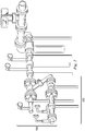
- Figure 1 illustrates a schematic sectional drawing of an exemplary tandem supersonic ejector system.
- the first supersonic ejector includes an enclosure 11, which is airtight or substantially airtight that includes a suction port 12.
- the suction port 12 of the first supersonic ejector 10 may be annular, or any other shape that facilitates the desired flow path characteristics for the ejector suction port 12.
- the motive gas enters the nozzle 17 of the first supersonic ejector, is expanded through a constricted throat 13, and is further expanded through the diverging section of the nozzle to a much lower pressure and a supersonic velocity.
- This supersonic velocity motive gas exits nozzle 17 at exit 19 of the first supersonic ejector 10 and the resulting reduction in the pressure draws the off gas into the ejector through the suction port 12.
- the combined motive gas and the off gas proceed to a diffuser 18 of the first supersonic ejector 10 having a larger throat 14 than that of the nozzle 17.
- the cross sectional area of the throat 14 of the diffuser 18 of the first ejector 10 is larger in size than the cross sectional area of the throat 13 of the nozzle 17. Due to the converging and then diverging sections of the cross section area of the channel through the diffuser 18 the speed of the motive gas and entrained off gas decreases.
- the mixture of the motive gas and the off gas exits the ejector 10 at a discharge end 15 of the diffuser 18 at higher pressure than that of the off gas.
- the end of the diffuser 18 exits into a conduit 16 leading to an enclosure 21, which is air tight or substantially air tight, that includes a suction port 22 of the second supersonic ejector 20.
- the suction port 22 of the second supersonic ejector 20 may be annular.
- the motive gas enters a nozzle 27 of the second supersonic ejector 20 and proceeds to a constricted throat 23, is expanded through the diverging section of the nozzle 27 and exits the nozzle 27 at an exit 29 and proceeds to diffuser 28 having a larger throat 24 than throat 23 of nozzle 27.
- the cross sectional area of the channel through the second supersonic ejector 20 also increases in size from throat 23 of the nozzle 27 to the throat 24 of the diffuser 28.
- This increases the velocity of the motive gas as it passes through throat 23 and the diverging section of the nozzle 27 and reduces the pressure drawing the exit gas from the first supersonic ejector 10 passing through the conduit 16 into the ejector 20 through suction port 22. Due to the converging and diverging cross section areas of the channel through the diffuser the speed of the motive gas and entrained off gas decreases in the diffuser.
- the mixture of the motive gas and the gas in the conduit 16 exits the ejector 20 at a discharge end 25 of the diffuser 28.
- the discharge end 25 of the diffuser 28 of the second supersonic ejector 20 feeds a conduit, which may be a pipe or other gas communicating line to recirculate the off gas combined with the motive gas for further processing.
- a motive gas at a higher pressure than the off gas in the case of a pipeline the natural gas within the line, and in the case of a chemical plant the process steam, is injected into the nozzle 17 of the first supersonic ejector 10.
- the cross sectional area of the ejector 10 narrows to a throat section 13 of the first supersonic ejector 10. This increases the velocity of the gas as it passes through the throat 13 and continues to expand through the diverging section of the nozzle 17 to the exit 19, which creates a lower pressure at the suction inlet 12 of the first supersonic ejector 10. This draws the off gas within the enclosure 11 into the first supersonic ejector.
- the off gas is drawn into and entrained with the motive gas passing through the first supersonic ejector 10. Downstream the cross sectional area of the throat 14 of the diffuser 18 is larger than the throat 13 of the nozzle 17.
- the diffuser 18 expands to the discharge end 15 or is fed to the suction port 22 for the second supersonic ejector 20.
- a second motive gas is fed to the nozzle 27 of the second supersonic ejector 20, which narrows to the throat 23.
- the gas velocity increases and the pressure drops drawing the off gas into the nozzle and leaves at the exit 29.
- the cross sectional area of the second supersonic ejector 20 also increases to the throat 24 of the diffuser 28 and then further expands to the discharge end 25.
- the discharge end 25 then feeds a line (not shown) which directs the recompressed off gas to subsequent processing at a higher pressure.
- the nozzles 17 and 27 of the supersonic ejectors 10, 20 are adjustable relative to the diffusers 18 and 28. Typically this is done by having the nozzle 17, 27 threaded and mounted on receiving threads on the enclosure or on a portion of the inlet to the diffuser 18, 28 in a manner not to close the suction port.
- the ejectors 10, 20 may be designed so that the first supersonic ejector 10 is operated at an exit Mach number from about 2.4 to about 2.6 and the second supersonic ejector 20 is operated at an exit Mach number from about 1.6 to about 1.8.
- the ratio of the cross section area of the nozzle exit 19 to the nozzle throat 13 may be from about 2.9 to about 3.2, preferably from about 3.0 to about 3.1.
- the ratio of the cross section area of the nozzle exit 29 to the nozzle throat 23 may be from about 1.30 to about 1.45, preferably from about 1.35 to about 1.40.
- the ratio of the area of the throat 14 of the diffuser 18 to the throat 13 of the nozzle 17 of the first supersonic ejector 10 may range from about 4.60 to about 4.90, preferably from 4.70 to 4.80.
- the ratio of the area of the throat 24 of the diffuser 28 to the throat 23 of the nozzle 27 of the second supersonic ejector 20 may range from about 1.70 to about 1.90, preferably from about 1.80 to about 1.90.
- the ratio of the motive gas flow rate to the first supersonic gas ejector to the off gas flow rate is from about 32 to about 45. (e.g. either g per g or Kg per Kg as this is a unitless ratio).
- the ratio between the motive gas flow rate to the second supersonic gas ejector and the discharge flow from the first supersonic ejector is from about 20 to about 25.
- Figure 2 of the '342 application illustrates Mach number contours at the exit of a supersonic nozzle and diffuser
- Figure 3 of the '342 application illustrates Stagnation Pressure Contours at Exit of Supersonic Nozzle and Diffuser
- Figure 4 of the '342 application illustrates the overall performance of the two-Stage Supersonic Ejector
- Figure 5 of the '342 application illustrates overall performance of the two-Stage Supersonic Ejector
- Figure 6 of the '342 application illustrates overall performance of the two-Stage Supersonic Ejector.
- Figure 2 illustrates a tandem supersonic ejector system implementation in a gas plant, where the system is not in a unitary housing.
- the exemplary tandem supersonic ejector system shown in Figure 2 illustrates the relative size of a tandem ejector system.
- the tandem ejector system illustrated in Figure 2 nonetheless encompasses between about 24 and about 36 inches in width, between about 20 and about 30 inches in height, and between about 12 and about 20 inches in depth.
- these dimensions only include the tandem ejectors, and do not include the subsequent valving illustrated in Figure 2 .
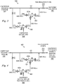
- FIG. 3 illustrates an exemplary schematic configuration of an implementation of a tandem supersonic ejector system 300 of the disclosure.
- the system 300 generally includes tandem supersonic ejectors 302a, 302b.
- the first ejector 302a may receive a compressor discharge pressure 304 at a high pressure input and a compressor gas seal vent 308 at a low pressure input.
- the output of the first ejector 302a may be communicated to a low pressure input of a second ejector 302b, and a regulated compressor discharge pressure 304 may be provided to the high pressure input of the second ejector 302b.
- the output of the second ejector 302b may be communicated to a gas turbine fuel system 306.
- the compressor gas seal vent 308 which would normally be vented to the atmosphere, is mixed in with the gas turbine fuel system 306 input via the tandem supersonic ejectors of the present disclosure.
- FIG 4 illustrates another exemplary schematic configuration of an implementation of a tandem supersonic ejector system 400 of the disclosure.
- the tandem ejector system 400 may be configured to receive a compressor discharge pressure 404 at a high-pressure input for each of two supersonic ejectors 402.
- the first supersonic ejector 402a may be configured to receive a compressor gas seal vent or a trap from an oil seal at a low pressure input 408.
- the output of the first supersonic ejector 402a may be communicated to a low pressure input of the second supersonic ejector 402b.
- the output of the second supersonic ejector 402b may be communicated to a compressor station inlet manifold 406 (or boosting system if required).
- tandem supersonic ejector systems can be combined with other ejector systems, including other tandem ejector systems, to form a series or chain of ejector systems.
- the number of ejectors in the system may be increased to 3, 4, 5, or more ejectors in a similar configuration as disclosed in at least one of the embodiments presented herein.
- the tandem configuration may be expanded to include between 3 and about 6 or more supersonic ejectors.
- FIG. 5 illustrates an exemplary tandem supersonic ejector system manufactured assembled in a unitary housing.
- the exemplary system 500 includes a unitary housing 506, which may be a single block of metal that has been machined and/or drilled out to receive the tandem supersonic ejectors therein.
- the metal may be any rigid metal such as iron based metals, titanium, aluminum, or any alloy metal commonly used in the compressor or turbine valve or piping arts.
- the outer surface of the housing 506 may include a plurality of connection flanges configured to receive or otherwise connect to piping for inputs and outputs. More particularly, flange 508 may be configured to connect to a high pressure input to a first supersonic ejector 502.
- Flange 514 may be configured to connect to the output line for the first supersonic ejector 502.
- Flange 510 may be configured as a high pressure input for a second supersonic ejector 504, and flange 512 may be configured as a low-pressure suction input for the second supersonic detector 504.
- the output of the second ejector 504 may be communicated to a low pressure input of the first ejector 502, thus forming the tandem ejector configuration of system 500.
- Figure 6 illustrates a partially exploded view of an exemplary tandem supersonic ejector system manufactured in a unitary housing.
- the exploded view illustrates the unitary block of metal that may be used to form the housing 506 for the exemplary ejector system.
- the exploded view of Figure 6 clearly illustrates that a plurality of bores may be formed in the unitary block housing 506 to form the unitary casing within which the supersonic ejectors may be contained.
- a first bore 520 may be formed longitudinally through the block 506, and the first bore 520 may be configured to receive the first ejector 502 therein.
- a second bore 530 may be formed in the block 506 and configured to receive the second ejector 504 therein.
- the second bore 530 may be positioned to terminate into the first bore 520, and as such, the output of the first ejector 504 may be communicated to the low-pressure suction input of the second ejector 502.
- a third bore 540 may be formed in the block 506, and the third bore may be configured to terminate in the second bore 530, and as such, the third bore 540 may be used to communicate with the low-pressure suction input of the second ejector 504.
- each of the respective bores may be formed into the block housing in a configuration where each of the bores is parallel to each other.
- the respective bores may be positioned such that the angle between the respective bores is between 0o and about 180o. Additional threaded bores may be formed at various locations in the block 506 to secure the various flanges 514, 508, 512, 510 to the block 506.
- the bores may be formed with threaded interior walls on the bores formed therein.
- the respective ejector assemblies or components thereof may be configured with threaded outer walls, such that the ejector assemblies or components may be threaded into the unitary block housing to form the desired system.
- the ejector assemblies may be sized and shaped to be slidably received and secured into a bore formed in the main body 506. In this embodiment there will generally be a securing mechanism configured to maintain the ejector assemblies in the respective bores at the desired position.
- the exemplary embodiments illustrated in Figures 5 and 6 use the flanges 508, 510, 512, 514 bolted to the main body 506 to secure the ejector assemblies in their respective bores.
- the bolted flanges 508, 510, 512, 514 are illustrated in the exemplary embodiments shown herein, Applicants appreciate that other equally effective methods for securing the ejector assemblies in their respective bores may be used without departing from the scope of the disclosure.
- the ejector assemblies may include any number of the ejector components, and as such may include a full ejector or a partial ejector. In embodiments where the assembly includes only a partial assembly, generally the remaining components of the ejector may be preformed into the housing, i.e., permanently drilled or otherwise machined into the housing 506.
- the overall size of the ejector system 500 is substantially reduced.
- the x and y dimensions illustrated on Figure 6 may be between about 8, 10, or 12 inches and about 12, 14, or 16 inches for each of the embodiments of the tandem supersonic ejector system disclosed herein.
- the z dimension may be between about 2 1 ⁇ 2 inches and about 6 1 ⁇ 2 inches for each of the embodiments of the tandem supersonic ejector system disclosed herein.
- Applicants have reduced the size of the tandem supersonic ejector system by more than 200%.
- manufacturing the tandem supersonic ejectors system from a unitary block of steel substantially reduces manufacturing costs and maintenance issues, while improving the reliability of the system.
- the ejector assemblies may be manufactured from a metal or metal alloy.
- the metal or metal alloy may be selected for the specific application, i.e., for temperature, strength, or chemical reactivity considerations that accompany each application.
- exemplary materials that may be used to manufacture the ejector assemblies include metals, iron, steel, titanium, and various alloys of these materials with additional elements added thereto.
- the ejectors may be manufactured from a non-metallic material, such as a ceramic or other rigid non-metallic material.
- the housing may also be manufactured from the same exemplary materials as the ejector assemblies. However, in selecting the appropriate material for the respective elements, the ability of the material to be precisely machined is a primary factor.
- Embodiments of the disclosure may generally provide a tandem supersonic ejector system.
- the system may include a first supersonic ejector that receives a compressor discharge at a high pressure input and a compressor gas seal vent line at a low pressure input.
- a second supersonic ejector may be configured to receive the compressor discharge pressure at a high pressure input and receive the output of the first supersonic ejector at the low pressure input to the second ejector.
- the output of the second ejector may be communicated to a gas turbine fuel system after being passed through a fuel regulator.
- Both the first and second supersonic ejectors are contained in a unitary housing that comprises a block of metal that has been milled or drilled to receive the ejectors therein. The resulting size of the block of metal containing the ejectors will generally be about 12x12x5 inches.
- Embodiments of the disclosure may further provide a tandem supersonic ejector system that includes a block of metal or an alloy that has a first bore formed therethrough, where the first bore extends substantially through the block and is sized to receive a first ejector therein.
- the block further includes a second bore formed therein, where a first end of the second bore originates proximate an outer edge of the block and a second end of the second bore terminates proximate the first bore and is in communication therewith.
- the second bore may be sized to receive a second supersonic ejector therein.
- the originating ends of the bores for the first and second ejectors may include fittings threadably secured to the block, and where the fittings are configured to engage pipe flanges.
- the length and width of the block may be between about 8 inches and about 16 inches, and the height between about 2 1 ⁇ 2 inches and about 6 1 ⁇ 2 inches.
Landscapes
- Engineering & Computer Science (AREA)
- Physics & Mathematics (AREA)
- Fluid Mechanics (AREA)
- Mechanical Engineering (AREA)
- General Engineering & Computer Science (AREA)
- Jet Pumps And Other Pumps (AREA)
Claims (3)
- Tandemultraschallejektorpaket, umfassend:ein einstückiges Gehäuse (506), das aus einem Vollmaterialstück herausgearbeitet ist;eine erste Bohrung (520), die durch das Gehäuse (506) gebildet ist;eine zweite Bohrung (530), die in dem Gehäuse (506) gebildet ist, die nahe der ersten Bohrung (520) und in Verbindung mit der ersten Bohrung (520) endet;eine erste Ultraschallejektoranordnung (502), die in der ersten Bohrung positioniert und darin durch einen ersten Eingangsseitenflansch (508) befestigt ist, der über einer Eingangsseite der ersten Bohrung (520) positioniert ist, und ein Ausgangsseitenflansch (514), der über einer Ausgangsseite der ersten Bohrung (520) positioniert ist; undeine zweite Ultraschallejektoranordnung (504), die in der zweiten Bohrung (530) positioniert und darin durch einen zweiten Eingangsseitenflansch (510) befestigt ist, der über einer Eingangsseite der zweiten Bohrung (530) positioniert ist,wobei eine Ausgangsseite der zweiten Bohrung in einem Saugeingang der ersten Ultraschallejektoranordnung (502) endet.
- Tandemultraschallejektorpaket nach Anspruch 1, wobei entsprechende Eingänge der ersten und zweiten Ultraschallejektoranordnungen (502, 504) konfiguriert sind, mit einer Verdichterdruckleitung zu kommunizieren.
- Tandemultraschallejektorpaket nach Anspruch 2, wobei ein Saugeingang der zweiten Ultraschallejektoranordnung (504) konfiguriert ist, mit einer Verdichtergasdichtungsentlüftungsleitung oder einer Fallenleitung von einer Kompressoröldichtung zu kommunizieren.
Applications Claiming Priority (2)
| Application Number | Priority Date | Filing Date | Title |
|---|---|---|---|
| US9540908P | 2008-09-09 | 2008-09-09 | |
| PCT/US2009/056323 WO2010030640A1 (en) | 2008-09-09 | 2009-09-09 | Supersonic ejector package |
Publications (3)
| Publication Number | Publication Date |
|---|---|
| EP2331829A1 EP2331829A1 (de) | 2011-06-15 |
| EP2331829A4 EP2331829A4 (de) | 2015-06-10 |
| EP2331829B1 true EP2331829B1 (de) | 2018-05-09 |
Family
ID=42005444
Family Applications (1)
| Application Number | Title | Priority Date | Filing Date |
|---|---|---|---|
| EP09813517.1A Not-in-force EP2331829B1 (de) | 2008-09-09 | 2009-09-09 | Überschall-ausstosspaket |
Country Status (6)
| Country | Link |
|---|---|
| US (1) | US8672644B2 (de) |
| EP (1) | EP2331829B1 (de) |
| CN (1) | CN102203435B (de) |
| AU (1) | AU2009291925B2 (de) |
| CA (1) | CA2736412C (de) |
| WO (1) | WO2010030640A1 (de) |
Families Citing this family (11)
| Publication number | Priority date | Publication date | Assignee | Title |
|---|---|---|---|---|
| WO2010030640A1 (en) | 2008-09-09 | 2010-03-18 | Dresser-Rand Company | Supersonic ejector package |
| US9163521B2 (en) * | 2011-07-09 | 2015-10-20 | Dresser-Rand Company | Gas turbine engine with supersonic compressor |
| EP2734101A4 (de) * | 2011-07-18 | 2015-06-03 | Clearear Inc | System für den zugriff auf körperöffnungen und verfahren |
| WO2017030948A1 (en) * | 2015-08-19 | 2017-02-23 | The Regents Of The University Of California | Shock injector for low-laser energy electron injection in a laser plasma accelerator |
| KR101685998B1 (ko) | 2016-09-21 | 2016-12-13 | (주)브이텍 | 프로파일을 이용한 진공 펌프 |
| US11231055B1 (en) * | 2019-06-05 | 2022-01-25 | Facebook Technologies, Llc | Apparatus and methods for fluidic amplification |
| CN112879795B (zh) * | 2019-11-29 | 2025-02-25 | 中集安瑞科工程科技有限公司 | 一种具有低液位物料抽提装置的低温全容罐 |
| US20220282739A1 (en) * | 2021-03-05 | 2022-09-08 | Honeywell International Inc. | Mixture entrainment device |
| US11828223B2 (en) | 2021-05-28 | 2023-11-28 | Honeywell International Inc. | Variable jet pump |
| US12234840B2 (en) | 2022-06-07 | 2025-02-25 | Honeywell International Inc. | Jet pump system |
| US20240189785A1 (en) * | 2022-11-14 | 2024-06-13 | Dean Lee Millar | Measure to Improve Liquid-Gas Eductor Performance |
Family Cites Families (30)
| Publication number | Priority date | Publication date | Assignee | Title |
|---|---|---|---|---|
| FR507184A (fr) * | 1918-12-21 | 1920-09-07 | Brown | Stabilisation d'éjecteurs à vapeur ou à gaz |
| US1437819A (en) * | 1920-09-11 | 1922-12-05 | Westinghouse Electric & Mfg Co | Ejector |
| US4194924A (en) | 1978-12-13 | 1980-03-25 | The United States Of America As Represented By The Secretary Of The Air Force | Process for reclaiming aircraft fuel tank purging fluids |
| US4237692A (en) * | 1979-02-28 | 1980-12-09 | The United States Of America As Represented By The United States Department Of Energy | Air ejector augmented compressed air energy storage system |
| SE427955B (sv) * | 1980-05-21 | 1983-05-24 | Piab Ab | Multiejektor |
| DE3025525A1 (de) * | 1980-07-05 | 1982-01-28 | Jürgen 4477 Welver Volkmann | Ejektorvorrichtung |
| IL67012A (en) * | 1982-10-18 | 1987-03-31 | Dan Greenberg | Ejector device and method for producing same |
| US4790054A (en) * | 1985-07-12 | 1988-12-13 | Nichols William O | Multi-stage venturi ejector and method of manufacture thereof |
| GB2177618B (en) | 1985-07-13 | 1989-07-19 | Adrian Philip Boyes | Gas/liquid contacting |
| US4835961A (en) | 1986-04-30 | 1989-06-06 | United Technologies Corporation | Fluid dynamic pump |
| US5228839A (en) * | 1991-05-24 | 1993-07-20 | Gast Manufacturing Corporation | Multistage ejector pump |
| US5380822A (en) | 1992-07-27 | 1995-01-10 | Novacor Chemicals (International) S.A. | Water assisted devolatilization |
| US5372005A (en) | 1992-09-14 | 1994-12-13 | Lawler; Shawn P. | Method and apparatus for power generation |
| US5628623A (en) * | 1993-02-12 | 1997-05-13 | Skaggs; Bill D. | Fluid jet ejector and ejection method |
| US5884472A (en) | 1995-10-11 | 1999-03-23 | Stage Iii Technologies, L.C. | Alternating lobed mixer/ejector concept suppressor |
| US5946904A (en) * | 1997-08-12 | 1999-09-07 | Boehnlein; John J. | Ejector ramjet engine |
| SE511716E5 (sv) * | 1998-03-20 | 2009-01-28 | Piab Ab | Ejektorpump |
| WO2000011113A1 (en) | 1998-08-21 | 2000-03-02 | Schumann-Sasol (South Africa) (Proprietary) Limited | Process for distilling fischer-tropsch derived paraffinic hydrocarbons |
| DE29916531U1 (de) * | 1999-09-20 | 2001-02-08 | Volkmann, Thilo, 59514 Welver | Ejektorpumpe |
| CN2410608Y (zh) * | 1999-12-10 | 2000-12-13 | 珠海市声速科技有限公司 | 超音速四头自带补水超节能装置 |
| US6322327B1 (en) * | 2000-01-13 | 2001-11-27 | Walker-Dawson Interests, Inc. | Jet pump for transfer of material |
| US6330821B1 (en) | 2000-02-14 | 2001-12-18 | The Goodyear Tire & Rubber Company | Method of detecting expansion vessel leakage |
| JP2003021100A (ja) | 2001-07-06 | 2003-01-24 | Tokico Ltd | エジェクタおよび負圧供給装置 |
| GB0128878D0 (en) | 2001-12-03 | 2002-01-23 | Boc Group Plc | Metallurgical lance and apparatus |
| DE10250532B3 (de) * | 2002-10-29 | 2004-07-01 | J. Schmalz Gmbh | Treibgas betriebene Ejektoranordnung |
| US20050089408A1 (en) * | 2003-05-09 | 2005-04-28 | Solomon Jason D. | Fluid ejector pumps |
| JP2005163619A (ja) * | 2003-12-02 | 2005-06-23 | Smc Corp | 真空発生用ユニット |
| DE102004034670B3 (de) * | 2004-07-17 | 2005-10-27 | Festo Ag & Co. | Vakuum-Saugdüse und Verfahren zu ihrer Herstellung |
| CA2560814C (en) * | 2006-09-25 | 2014-08-26 | Transcanada Pipelines Limited | Tandem supersonic ejectors |
| WO2010030640A1 (en) | 2008-09-09 | 2010-03-18 | Dresser-Rand Company | Supersonic ejector package |
-
2009
- 2009-09-09 WO PCT/US2009/056323 patent/WO2010030640A1/en not_active Ceased
- 2009-09-09 US US12/556,264 patent/US8672644B2/en not_active Expired - Fee Related
- 2009-09-09 AU AU2009291925A patent/AU2009291925B2/en not_active Ceased
- 2009-09-09 CN CN200980141701.4A patent/CN102203435B/zh not_active Expired - Fee Related
- 2009-09-09 CA CA2736412A patent/CA2736412C/en not_active Expired - Fee Related
- 2009-09-09 EP EP09813517.1A patent/EP2331829B1/de not_active Not-in-force
Non-Patent Citations (1)
| Title |
|---|
| None * |
Also Published As
| Publication number | Publication date |
|---|---|
| US8672644B2 (en) | 2014-03-18 |
| US20100108167A1 (en) | 2010-05-06 |
| CA2736412A1 (en) | 2010-03-18 |
| AU2009291925A1 (en) | 2010-03-18 |
| EP2331829A1 (de) | 2011-06-15 |
| WO2010030640A1 (en) | 2010-03-18 |
| AU2009291925B2 (en) | 2015-11-19 |
| CN102203435B (zh) | 2014-09-10 |
| EP2331829A4 (de) | 2015-06-10 |
| CN102203435A (zh) | 2011-09-28 |
| CA2736412C (en) | 2015-11-24 |
Similar Documents
| Publication | Publication Date | Title |
|---|---|---|
| EP2331829B1 (de) | Überschall-ausstosspaket | |
| EP2094971B1 (de) | Tandem-überschallejektoren | |
| EP2180162B2 (de) | Gasturbinenejektor und Betriebsverfahren | |
| US20130167566A1 (en) | Ejectors and Methods of Manufacture | |
| MY150371A (en) | Gas liquefaction and separation device | |
| US5064449A (en) | Fluid degassing | |
| CN103527526A (zh) | 高效可调喷嘴喷射器 | |
| EP0995909A1 (de) | Flüssiggas-strahlgerät und varianten | |
| RU2142072C1 (ru) | Жидкостно-газовый эжектор | |
| US20070025862A1 (en) | Compressible gas ejector with unexpanded motive gas-load gas interface | |
| US6364626B1 (en) | Liquid-gas jet apparatus | |
| Grave | Steam jet vacuum pumps | |
| Olšiak et al. | Reduction of the suction pressure of a liquid ring vacuum pump with a supersonic gas ejector | |
| GB2536291A (en) | Jet pump | |
| RU223851U1 (ru) | Эжектор струйный двухступенчатый универсальный регулируемый | |
| RU2142076C1 (ru) | Способ работы насосно-эжекторной установки и многоступенчатая насосно-эжекторная установка для его реализации | |
| RU2567413C2 (ru) | Способ ремонта магистрального газопровода и передвижная газоперекачивающая установка для его осуществления | |
| RU2133884C1 (ru) | Жидкостно-газовый эжектор (варианты) | |
| RU2506112C2 (ru) | Устройство для очистки пара или газа от инородных включений | |
| RU2166134C1 (ru) | Способ работы насосно-эжекторной установки и установка для его осуществления | |
| WO2026022494A3 (en) | Turbine housing | |
| Phitakwinai et al. | Effect of nozzle position on water ejector efficiency | |
| SK7523Y1 (sk) | Dvojstupňový integrovaný supersonický ejektor a konfigurácia prúdového a objemového stroja | |
| SK50452015A3 (sk) | Dvojstupňový integrovaný supersonický ejektor a konfigurácia prúdového a objemového stroja | |
| UA46287A (uk) | Багатосопловий ежектор |
Legal Events
| Date | Code | Title | Description |
|---|---|---|---|
| PUAI | Public reference made under article 153(3) epc to a published international application that has entered the european phase |
Free format text: ORIGINAL CODE: 0009012 |
|
| 17P | Request for examination filed |
Effective date: 20110404 |
|
| AK | Designated contracting states |
Kind code of ref document: A1 Designated state(s): AT BE BG CH CY CZ DE DK EE ES FI FR GB GR HR HU IE IS IT LI LT LU LV MC MK MT NL NO PL PT RO SE SI SK SM TR |
|
| AX | Request for extension of the european patent |
Extension state: AL BA RS |
|
| DAX | Request for extension of the european patent (deleted) | ||
| RA4 | Supplementary search report drawn up and despatched (corrected) |
Effective date: 20150511 |
|
| RIC1 | Information provided on ipc code assigned before grant |
Ipc: F04F 5/18 20060101ALI20150504BHEP Ipc: F04F 5/46 20060101ALI20150504BHEP Ipc: F15C 1/12 20060101AFI20150504BHEP |
|
| 17Q | First examination report despatched |
Effective date: 20160805 |
|
| STAA | Information on the status of an ep patent application or granted ep patent |
Free format text: STATUS: EXAMINATION IS IN PROGRESS |
|
| GRAP | Despatch of communication of intention to grant a patent |
Free format text: ORIGINAL CODE: EPIDOSNIGR1 |
|
| STAA | Information on the status of an ep patent application or granted ep patent |
Free format text: STATUS: GRANT OF PATENT IS INTENDED |
|
| INTG | Intention to grant announced |
Effective date: 20180215 |
|
| GRAS | Grant fee paid |
Free format text: ORIGINAL CODE: EPIDOSNIGR3 |
|
| GRAA | (expected) grant |
Free format text: ORIGINAL CODE: 0009210 |
|
| STAA | Information on the status of an ep patent application or granted ep patent |
Free format text: STATUS: THE PATENT HAS BEEN GRANTED |
|
| RAP1 | Party data changed (applicant data changed or rights of an application transferred) |
Owner name: DRESSER-RAND COMPANY |
|
| AK | Designated contracting states |
Kind code of ref document: B1 Designated state(s): AT BE BG CH CY CZ DE DK EE ES FI FR GB GR HR HU IE IS IT LI LT LU LV MC MK MT NL NO PL PT RO SE SI SK SM TR |
|
| REG | Reference to a national code |
Ref country code: GB Ref legal event code: FG4D |
|
| REG | Reference to a national code |
Ref country code: CH Ref legal event code: EP Ref country code: AT Ref legal event code: REF Ref document number: 997819 Country of ref document: AT Kind code of ref document: T Effective date: 20180515 |
|
| REG | Reference to a national code |
Ref country code: IE Ref legal event code: FG4D |
|
| REG | Reference to a national code |
Ref country code: DE Ref legal event code: R096 Ref document number: 602009052249 Country of ref document: DE |
|
| REG | Reference to a national code |
Ref country code: NL Ref legal event code: MP Effective date: 20180509 |
|
| REG | Reference to a national code |
Ref country code: FR Ref legal event code: PLFP Year of fee payment: 10 |
|
| REG | Reference to a national code |
Ref country code: LT Ref legal event code: MG4D |
|
| PG25 | Lapsed in a contracting state [announced via postgrant information from national office to epo] |
Ref country code: SE Free format text: LAPSE BECAUSE OF FAILURE TO SUBMIT A TRANSLATION OF THE DESCRIPTION OR TO PAY THE FEE WITHIN THE PRESCRIBED TIME-LIMIT Effective date: 20180509 Ref country code: ES Free format text: LAPSE BECAUSE OF FAILURE TO SUBMIT A TRANSLATION OF THE DESCRIPTION OR TO PAY THE FEE WITHIN THE PRESCRIBED TIME-LIMIT Effective date: 20180509 Ref country code: LT Free format text: LAPSE BECAUSE OF FAILURE TO SUBMIT A TRANSLATION OF THE DESCRIPTION OR TO PAY THE FEE WITHIN THE PRESCRIBED TIME-LIMIT Effective date: 20180509 Ref country code: NO Free format text: LAPSE BECAUSE OF FAILURE TO SUBMIT A TRANSLATION OF THE DESCRIPTION OR TO PAY THE FEE WITHIN THE PRESCRIBED TIME-LIMIT Effective date: 20180809 Ref country code: BG Free format text: LAPSE BECAUSE OF FAILURE TO SUBMIT A TRANSLATION OF THE DESCRIPTION OR TO PAY THE FEE WITHIN THE PRESCRIBED TIME-LIMIT Effective date: 20180809 Ref country code: FI Free format text: LAPSE BECAUSE OF FAILURE TO SUBMIT A TRANSLATION OF THE DESCRIPTION OR TO PAY THE FEE WITHIN THE PRESCRIBED TIME-LIMIT Effective date: 20180509 |
|
| PGFP | Annual fee paid to national office [announced via postgrant information from national office to epo] |
Ref country code: IT Payment date: 20180926 Year of fee payment: 10 Ref country code: FR Payment date: 20180924 Year of fee payment: 10 |
|
| PG25 | Lapsed in a contracting state [announced via postgrant information from national office to epo] |
Ref country code: GR Free format text: LAPSE BECAUSE OF FAILURE TO SUBMIT A TRANSLATION OF THE DESCRIPTION OR TO PAY THE FEE WITHIN THE PRESCRIBED TIME-LIMIT Effective date: 20180810 Ref country code: HR Free format text: LAPSE BECAUSE OF FAILURE TO SUBMIT A TRANSLATION OF THE DESCRIPTION OR TO PAY THE FEE WITHIN THE PRESCRIBED TIME-LIMIT Effective date: 20180509 Ref country code: NL Free format text: LAPSE BECAUSE OF FAILURE TO SUBMIT A TRANSLATION OF THE DESCRIPTION OR TO PAY THE FEE WITHIN THE PRESCRIBED TIME-LIMIT Effective date: 20180509 Ref country code: LV Free format text: LAPSE BECAUSE OF FAILURE TO SUBMIT A TRANSLATION OF THE DESCRIPTION OR TO PAY THE FEE WITHIN THE PRESCRIBED TIME-LIMIT Effective date: 20180509 |
|
| REG | Reference to a national code |
Ref country code: AT Ref legal event code: MK05 Ref document number: 997819 Country of ref document: AT Kind code of ref document: T Effective date: 20180509 |
|
| PG25 | Lapsed in a contracting state [announced via postgrant information from national office to epo] |
Ref country code: AT Free format text: LAPSE BECAUSE OF FAILURE TO SUBMIT A TRANSLATION OF THE DESCRIPTION OR TO PAY THE FEE WITHIN THE PRESCRIBED TIME-LIMIT Effective date: 20180509 Ref country code: DK Free format text: LAPSE BECAUSE OF FAILURE TO SUBMIT A TRANSLATION OF THE DESCRIPTION OR TO PAY THE FEE WITHIN THE PRESCRIBED TIME-LIMIT Effective date: 20180509 Ref country code: EE Free format text: LAPSE BECAUSE OF FAILURE TO SUBMIT A TRANSLATION OF THE DESCRIPTION OR TO PAY THE FEE WITHIN THE PRESCRIBED TIME-LIMIT Effective date: 20180509 Ref country code: SK Free format text: LAPSE BECAUSE OF FAILURE TO SUBMIT A TRANSLATION OF THE DESCRIPTION OR TO PAY THE FEE WITHIN THE PRESCRIBED TIME-LIMIT Effective date: 20180509 Ref country code: RO Free format text: LAPSE BECAUSE OF FAILURE TO SUBMIT A TRANSLATION OF THE DESCRIPTION OR TO PAY THE FEE WITHIN THE PRESCRIBED TIME-LIMIT Effective date: 20180509 Ref country code: CZ Free format text: LAPSE BECAUSE OF FAILURE TO SUBMIT A TRANSLATION OF THE DESCRIPTION OR TO PAY THE FEE WITHIN THE PRESCRIBED TIME-LIMIT Effective date: 20180509 Ref country code: PL Free format text: LAPSE BECAUSE OF FAILURE TO SUBMIT A TRANSLATION OF THE DESCRIPTION OR TO PAY THE FEE WITHIN THE PRESCRIBED TIME-LIMIT Effective date: 20180509 |
|
| REG | Reference to a national code |
Ref country code: DE Ref legal event code: R097 Ref document number: 602009052249 Country of ref document: DE |
|
| PG25 | Lapsed in a contracting state [announced via postgrant information from national office to epo] |
Ref country code: SM Free format text: LAPSE BECAUSE OF FAILURE TO SUBMIT A TRANSLATION OF THE DESCRIPTION OR TO PAY THE FEE WITHIN THE PRESCRIBED TIME-LIMIT Effective date: 20180509 |
|
| PLBE | No opposition filed within time limit |
Free format text: ORIGINAL CODE: 0009261 |
|
| STAA | Information on the status of an ep patent application or granted ep patent |
Free format text: STATUS: NO OPPOSITION FILED WITHIN TIME LIMIT |
|
| REG | Reference to a national code |
Ref country code: DE Ref legal event code: R119 Ref document number: 602009052249 Country of ref document: DE |
|
| 26N | No opposition filed |
Effective date: 20190212 |
|
| PG25 | Lapsed in a contracting state [announced via postgrant information from national office to epo] |
Ref country code: MC Free format text: LAPSE BECAUSE OF FAILURE TO SUBMIT A TRANSLATION OF THE DESCRIPTION OR TO PAY THE FEE WITHIN THE PRESCRIBED TIME-LIMIT Effective date: 20180509 |
|
| REG | Reference to a national code |
Ref country code: CH Ref legal event code: PL |
|
| GBPC | Gb: european patent ceased through non-payment of renewal fee |
Effective date: 20180909 |
|
| PG25 | Lapsed in a contracting state [announced via postgrant information from national office to epo] |
Ref country code: SI Free format text: LAPSE BECAUSE OF FAILURE TO SUBMIT A TRANSLATION OF THE DESCRIPTION OR TO PAY THE FEE WITHIN THE PRESCRIBED TIME-LIMIT Effective date: 20180509 |
|
| REG | Reference to a national code |
Ref country code: BE Ref legal event code: MM Effective date: 20180930 |
|
| REG | Reference to a national code |
Ref country code: IE Ref legal event code: MM4A |
|
| PG25 | Lapsed in a contracting state [announced via postgrant information from national office to epo] |
Ref country code: LU Free format text: LAPSE BECAUSE OF NON-PAYMENT OF DUE FEES Effective date: 20180909 |
|
| PG25 | Lapsed in a contracting state [announced via postgrant information from national office to epo] |
Ref country code: IE Free format text: LAPSE BECAUSE OF NON-PAYMENT OF DUE FEES Effective date: 20180909 Ref country code: DE Free format text: LAPSE BECAUSE OF NON-PAYMENT OF DUE FEES Effective date: 20190402 |
|
| PG25 | Lapsed in a contracting state [announced via postgrant information from national office to epo] |
Ref country code: CH Free format text: LAPSE BECAUSE OF NON-PAYMENT OF DUE FEES Effective date: 20180930 Ref country code: LI Free format text: LAPSE BECAUSE OF NON-PAYMENT OF DUE FEES Effective date: 20180930 Ref country code: BE Free format text: LAPSE BECAUSE OF NON-PAYMENT OF DUE FEES Effective date: 20180930 |
|
| PG25 | Lapsed in a contracting state [announced via postgrant information from national office to epo] |
Ref country code: GB Free format text: LAPSE BECAUSE OF NON-PAYMENT OF DUE FEES Effective date: 20180909 |
|
| PG25 | Lapsed in a contracting state [announced via postgrant information from national office to epo] |
Ref country code: MT Free format text: LAPSE BECAUSE OF NON-PAYMENT OF DUE FEES Effective date: 20180909 |
|
| PG25 | Lapsed in a contracting state [announced via postgrant information from national office to epo] |
Ref country code: TR Free format text: LAPSE BECAUSE OF FAILURE TO SUBMIT A TRANSLATION OF THE DESCRIPTION OR TO PAY THE FEE WITHIN THE PRESCRIBED TIME-LIMIT Effective date: 20180509 |
|
| PG25 | Lapsed in a contracting state [announced via postgrant information from national office to epo] |
Ref country code: HU Free format text: LAPSE BECAUSE OF FAILURE TO SUBMIT A TRANSLATION OF THE DESCRIPTION OR TO PAY THE FEE WITHIN THE PRESCRIBED TIME-LIMIT; INVALID AB INITIO Effective date: 20090909 Ref country code: PT Free format text: LAPSE BECAUSE OF FAILURE TO SUBMIT A TRANSLATION OF THE DESCRIPTION OR TO PAY THE FEE WITHIN THE PRESCRIBED TIME-LIMIT Effective date: 20180509 |
|
| PG25 | Lapsed in a contracting state [announced via postgrant information from national office to epo] |
Ref country code: MK Free format text: LAPSE BECAUSE OF NON-PAYMENT OF DUE FEES Effective date: 20180509 Ref country code: CY Free format text: LAPSE BECAUSE OF FAILURE TO SUBMIT A TRANSLATION OF THE DESCRIPTION OR TO PAY THE FEE WITHIN THE PRESCRIBED TIME-LIMIT Effective date: 20180509 |
|
| PG25 | Lapsed in a contracting state [announced via postgrant information from national office to epo] |
Ref country code: IS Free format text: LAPSE BECAUSE OF FAILURE TO SUBMIT A TRANSLATION OF THE DESCRIPTION OR TO PAY THE FEE WITHIN THE PRESCRIBED TIME-LIMIT Effective date: 20180909 |
|
| PG25 | Lapsed in a contracting state [announced via postgrant information from national office to epo] |
Ref country code: IT Free format text: LAPSE BECAUSE OF NON-PAYMENT OF DUE FEES Effective date: 20190909 |
|
| PG25 | Lapsed in a contracting state [announced via postgrant information from national office to epo] |
Ref country code: FR Free format text: LAPSE BECAUSE OF NON-PAYMENT OF DUE FEES Effective date: 20190930 |