EP2332155B1 - Culasse d aimant, composant micromecanique et procede de fabrication pour une culasse d' aimant et un composant micromecanique - Google Patents
Culasse d aimant, composant micromecanique et procede de fabrication pour une culasse d' aimant et un composant micromecanique Download PDFInfo
- Publication number
- EP2332155B1 EP2332155B1 EP09781413.1A EP09781413A EP2332155B1 EP 2332155 B1 EP2332155 B1 EP 2332155B1 EP 09781413 A EP09781413 A EP 09781413A EP 2332155 B1 EP2332155 B1 EP 2332155B1
- Authority
- EP
- European Patent Office
- Prior art keywords
- yoke
- magnet
- intermediate frame
- pole shoe
- axis
- Prior art date
- Legal status (The legal status is an assumption and is not a legal conclusion. Google has not performed a legal analysis and makes no representation as to the accuracy of the status listed.)
- Not-in-force
Links
- 238000004519 manufacturing process Methods 0.000 title claims description 12
- 239000004020 conductor Substances 0.000 claims description 36
- 230000005415 magnetization Effects 0.000 claims description 16
- 239000000853 adhesive Substances 0.000 description 8
- 230000001070 adhesive effect Effects 0.000 description 8
- XUIMIQQOPSSXEZ-UHFFFAOYSA-N Silicon Chemical compound [Si] XUIMIQQOPSSXEZ-UHFFFAOYSA-N 0.000 description 5
- 229910052710 silicon Inorganic materials 0.000 description 5
- 239000010703 silicon Substances 0.000 description 5
- XEEYBQQBJWHFJM-UHFFFAOYSA-N Iron Chemical compound [Fe] XEEYBQQBJWHFJM-UHFFFAOYSA-N 0.000 description 4
- 238000013461 design Methods 0.000 description 4
- 238000011161 development Methods 0.000 description 4
- 230000018109 developmental process Effects 0.000 description 4
- 238000005530 etching Methods 0.000 description 4
- 239000000696 magnetic material Substances 0.000 description 4
- 238000000034 method Methods 0.000 description 4
- 239000002245 particle Substances 0.000 description 3
- 230000015572 biosynthetic process Effects 0.000 description 2
- 239000011521 glass Substances 0.000 description 2
- 229910052742 iron Inorganic materials 0.000 description 2
- 239000002923 metal particle Substances 0.000 description 2
- 230000003068 static effect Effects 0.000 description 2
- 238000013459 approach Methods 0.000 description 1
- 239000002131 composite material Substances 0.000 description 1
- 238000010276 construction Methods 0.000 description 1
- 238000011109 contamination Methods 0.000 description 1
- 230000007423 decrease Effects 0.000 description 1
- 238000005516 engineering process Methods 0.000 description 1
- 230000004907 flux Effects 0.000 description 1
- 238000010438 heat treatment Methods 0.000 description 1
- 238000010348 incorporation Methods 0.000 description 1
- 239000000463 material Substances 0.000 description 1
- 238000000059 patterning Methods 0.000 description 1
- 239000003351 stiffener Substances 0.000 description 1
- 239000013589 supplement Substances 0.000 description 1
- 239000000725 suspension Substances 0.000 description 1
- 238000004804 winding Methods 0.000 description 1
Images





Classifications
-
- H—ELECTRICITY
- H01—ELECTRIC ELEMENTS
- H01F—MAGNETS; INDUCTANCES; TRANSFORMERS; SELECTION OF MATERIALS FOR THEIR MAGNETIC PROPERTIES
- H01F7/00—Magnets
- H01F7/06—Electromagnets; Actuators including electromagnets
- H01F7/066—Electromagnets with movable winding
-
- G—PHYSICS
- G02—OPTICS
- G02B—OPTICAL ELEMENTS, SYSTEMS OR APPARATUS
- G02B26/00—Optical devices or arrangements for the control of light using movable or deformable optical elements
- G02B26/08—Optical devices or arrangements for the control of light using movable or deformable optical elements for controlling the direction of light
- G02B26/0816—Optical devices or arrangements for the control of light using movable or deformable optical elements for controlling the direction of light by means of one or more reflecting elements
- G02B26/0833—Optical devices or arrangements for the control of light using movable or deformable optical elements for controlling the direction of light by means of one or more reflecting elements the reflecting element being a micromechanical device, e.g. a MEMS mirror, DMD
- G02B26/0841—Optical devices or arrangements for the control of light using movable or deformable optical elements for controlling the direction of light by means of one or more reflecting elements the reflecting element being a micromechanical device, e.g. a MEMS mirror, DMD the reflecting element being moved or deformed by electrostatic means
-
- G—PHYSICS
- G02—OPTICS
- G02B—OPTICAL ELEMENTS, SYSTEMS OR APPARATUS
- G02B26/00—Optical devices or arrangements for the control of light using movable or deformable optical elements
- G02B26/08—Optical devices or arrangements for the control of light using movable or deformable optical elements for controlling the direction of light
- G02B26/0816—Optical devices or arrangements for the control of light using movable or deformable optical elements for controlling the direction of light by means of one or more reflecting elements
- G02B26/0833—Optical devices or arrangements for the control of light using movable or deformable optical elements for controlling the direction of light by means of one or more reflecting elements the reflecting element being a micromechanical device, e.g. a MEMS mirror, DMD
- G02B26/0858—Optical devices or arrangements for the control of light using movable or deformable optical elements for controlling the direction of light by means of one or more reflecting elements the reflecting element being a micromechanical device, e.g. a MEMS mirror, DMD the reflecting means being moved or deformed by piezoelectric means
-
- H—ELECTRICITY
- H01—ELECTRIC ELEMENTS
- H01F—MAGNETS; INDUCTANCES; TRANSFORMERS; SELECTION OF MATERIALS FOR THEIR MAGNETIC PROPERTIES
- H01F7/00—Magnets
- H01F7/02—Permanent magnets [PM]
- H01F7/0273—Magnetic circuits with PM for magnetic field generation
-
- H—ELECTRICITY
- H02—GENERATION; CONVERSION OR DISTRIBUTION OF ELECTRIC POWER
- H02K—DYNAMO-ELECTRIC MACHINES
- H02K33/00—Motors with reciprocating, oscillating or vibrating magnet, armature or coil system
- H02K33/18—Motors with reciprocating, oscillating or vibrating magnet, armature or coil system with coil systems moving upon intermittent or reversed energisation thereof by interaction with a fixed field system, e.g. permanent magnets
-
- H—ELECTRICITY
- H01—ELECTRIC ELEMENTS
- H01F—MAGNETS; INDUCTANCES; TRANSFORMERS; SELECTION OF MATERIALS FOR THEIR MAGNETIC PROPERTIES
- H01F7/00—Magnets
- H01F7/02—Permanent magnets [PM]
- H01F7/0231—Magnetic circuits with PM for power or force generation
-
- Y—GENERAL TAGGING OF NEW TECHNOLOGICAL DEVELOPMENTS; GENERAL TAGGING OF CROSS-SECTIONAL TECHNOLOGIES SPANNING OVER SEVERAL SECTIONS OF THE IPC; TECHNICAL SUBJECTS COVERED BY FORMER USPC CROSS-REFERENCE ART COLLECTIONS [XRACs] AND DIGESTS
- Y10—TECHNICAL SUBJECTS COVERED BY FORMER USPC
- Y10T—TECHNICAL SUBJECTS COVERED BY FORMER US CLASSIFICATION
- Y10T29/00—Metal working
- Y10T29/49—Method of mechanical manufacture
- Y10T29/49002—Electrical device making
- Y10T29/4902—Electromagnet, transformer or inductor
- Y10T29/49071—Electromagnet, transformer or inductor by winding or coiling
-
- Y—GENERAL TAGGING OF NEW TECHNOLOGICAL DEVELOPMENTS; GENERAL TAGGING OF CROSS-SECTIONAL TECHNOLOGIES SPANNING OVER SEVERAL SECTIONS OF THE IPC; TECHNICAL SUBJECTS COVERED BY FORMER USPC CROSS-REFERENCE ART COLLECTIONS [XRACs] AND DIGESTS
- Y10—TECHNICAL SUBJECTS COVERED BY FORMER USPC
- Y10T—TECHNICAL SUBJECTS COVERED BY FORMER US CLASSIFICATION
- Y10T29/00—Metal working
- Y10T29/49—Method of mechanical manufacture
- Y10T29/49826—Assembling or joining
Definitions
- the invention relates to a magnetic yoke. Likewise, the invention relates to a micromechanical component. Furthermore, the invention relates to a production method for a magnetic yoke and a production method for a micromechanical component.
- a micromechanical component may have a magnetic drive, an electrostatic drive and / or a piezoelectric drive for adjusting an adjustable actuating element relative to a fixed support.
- the adjustable adjusting element is for example a mirror plate, which is adjustable by means of the drive about at least one axis of rotation, preferably about two axes of rotation.
- a micromechanical component with a magnetic drive has the advantage over a comparable component having an electrostatic drive that comparatively high torques can be achieved with industrially sensible current intensities of less than 100 mA.
- electrostatic comb drives In order to achieve corresponding torques by means of electrostatic comb drives, with gap spacings of approximately 5 ⁇ m, voltages in a range of several 100 V are necessary. The technical realization of such a voltage is relatively expensive, especially since risks of a rollover or a pull-ins exist.
- Another advantage of a magnetic drive over an electrostatic drive is the linear Lorentz force primarily related to the applied voltage.
- a micromechanical component with a magnetic drive the assembly and connection technology is often relatively expensive.
- a micromechanical component with a magnetic drive and an adjusting element which can be adjusted by two axes of rotation can therefore only be produced by means of a comparatively large amount of work.
- the EP 77 8 657 BI and the WO 2005/078509 A2 each describe a magnetic drive for adjusting an actuating element.
- the actuator is adjustable about two axes of rotation, the magnetic drives on a plurality of permanent magnets, which must be arranged in a preferred position with a relatively small distance from each other.
- the permanent magnets are to be arranged in the preferred position to each other so that the Magnetisicrungscardien the permanent magnets are not aligned parallel to each other.
- repulsive forces occur between the permanent magnets during the production of the magnetic drives. This makes the manufacture of the magnetic drives comparatively laborious and complicated. In particular, adhesive processes are not possible here.
- the EP 1858 141 A describes a two-dimensional scanner with a magnetic yoke, in the yoke gaps an adjustable trained actuator is arranged. Conductor tracks are formed on the actuating element, which have an asymmetry with respect to an axis that intersects the actuating element in the center, which axis is aligned perpendicular to the magnetic field lines of the magnetic yoke.
- the DE 37 23 776 A1 discloses the preamble of claim 1.
- the invention provides a magnetic yoke having the features of claim 1, a micromechanical component having the features of claim 5, a manufacturing method for a magnetic yoke having the features of claim 6 and a manufacturing method for a micromechanical component having the features of claim 7.
- FIGS. 1A and 1B show a cross section and a plan view for illustrating an embodiment of the magnetic yoke.
- Magnetic yoke 10 schematically represented as a cross-section comprises a hard magnet 12 with a magnetization direction 14.
- the magnet 12 can be a permanent magnet. After assembling the magnet yoke 10, the magnet magnet 12 can be magnetized from its individual components described below by means of a magnetization method.
- the magnetization direction 14 extends from a first side surface 16a to a second side surface 16b of the hard magnet 12.
- a yoke arm 18a and 18b made of a soft magnetic material is fixedly arranged.
- the two yoke arms 18a and 19b extend from the hard magnets 12 in a common direction and thereby span a yoke gap 20 on.
- the width of the yoke gap 20 along the magnetization direction 14 is therefore equal to the width of the hard magnet 12 between the side surfaces 16a and 16b.
- pole shoes 22a and 22b are fixedly arranged, which in FIG Figure 1A however, they are only sketched schematically.
- the pole pieces 22a and 22b are formed of a soft magnetic material.
- the pole pieces 22a and 22b are formed of a soft magnetic material.
- the pole pieces 22a and 22b may be formed integrally with the associated yoke arm 18a or 18b.
- the representation of the pole pieces 22a and 22b with the yoke arms 18a and 18b as two individual components is chosen here only on the basis of a better vividness.
- the two pole pieces 22a and 22b are arranged at a distance from one another on the yoke arms 18a and 18b.
- a yoke gap 24 is located between the first pole shoe 22a arranged on the first yoke arm 18a and the second pole thrust 22b arranged on the second yoke arm 18b.
- the yoke gap 24 has a maximum width bmax parallel to the magnetization direction 14 which is smaller than the distance between the two side surfaces 16a and 16b.
- In the yoke gap 24 is a magnetic field with magnetic field lines 26 before.
- the field lines 26 of the magnetic field in the interior of the yoke gap 24 are directed counter to the magnetization direction 14.
- FIG. 1B shows a plan view of the yoke 10 for more detailed description of the pole pieces 22a and 22b.
- the hard magnet 12 is in FIG. 1B shown only in dashed lines.
- the maximum width bmax of the yoke gap 16 is greater than a width br of an intermediate frame 30 is selected.
- the intermediate frame 30 can thus be arranged in the yoke gap 24 of the magnetic yoke 10 (see Fig. 1B ). On the structure and function of the intermediate frame 30 will be discussed in more detail below.
- a center plane 32 can be defined, which is aligned parallel to the magnetization direction 14 and the hard magnet 12 and the two yoke arms 18a and 18b intersects.
- the median plane 32 runs centrally parallel to the field lines both through the hard magnet 12 and through the two yoke arms 18a and 18b.
- the center plane 32 can divide the hard magnet 12 and / or at least one of the two yoke arms 18a and 18b into two mutually symmetrical halves.
- the pole pieces 22a and 22b of the magnetic yoke 10 are each formed such that their mass distribution has no symmetry with respect to the center plane 32.
- the magnetic yoke 10 can therefore be referred to as an unbalanced magnetic yoke.
- the median plane 32 divides a pole piece 22a into a first half 34a and a second half 36a, the first half 34a having an additional mass 38a opposite the second half 36a, which protrudes into the yoke gap 34.
- the additional mass 38a is preferably formed of a material having good magnetic flux characteristics.
- the additional mass 38a may be formed integrally with the pole piece 22a. It should be noted, however, that the pole shoes 22a and 22b may also be composed of a plurality of components which are at least partially spaced from each other.
- the additional mass 38a or 38b extends in a direction perpendicular to the width bmax of the yoke gap 24 along the entire first half 34a or 34b.
- the additional mass 38a may also have a smaller extent with respect to a direction perpendicular to the maximum width bmax.
- the center plane 32 divides both pole shoes 22a and 22b into a respective first half 34a or 34b with the additional mass 38a or 38b and a second half 36a or 36b without additional mass 38a or 38b.
- the midplane 32 divides only one pole shoe 22a or 22b into a first half 34a or 34b with an additional mass 38a or 38b in relation to the second half 36a or 36b.
- the other pole piece 22a or 22b may in this case have a mass distribution which is symmetrical with respect to the center plane 32.
- the asymmetry of the pole pieces 22a and 22b can also be described by defining a front side and a rear side of the magnetic yoke 10, with the yoke gap 20 and the yoke gap 24 extending from the front side to the rear side.
- the first of the two pole pieces 22a has a first side surface 40a on the front side and a second side surface 42a on the rear side.
- the first side surface 40a of the pole piece 22a has a first width b1 in a direction parallel to the maximum width bmax.
- the second side of the first pole piece 22a has a second width b2 not equal to the first width b1 in the direction parallel to the maximum width bmax.
- the first width b1 is greater than the second width b2 (see example of FIG. 1B ).
- the first pole piece 22a protrudes from the first yoke arm 18a on the first side face 40a by a first height into the yoke gap 24.
- the first pole piece 22a protrudes into the yoke gap 24 by a second height, not equal to the first height.
- the second pole piece 22b can also have a first side face 40b with the first width b1 on the rear side and a second side face 42b with the second width b2 on the front side. It should be noted, however, that a point-symmetrical design of the two pole pieces 22a and 22b is not a prerequisite for the technique described.
- the asymmetrical design of the pole pieces 22 causes a magnetic field in the yoke gap 24 which is asymmetrical with respect to the center plane 32, the field lines of the magnetic field, however, in FIG. 1B the sake of clarity are not shown.
- four corners 44-50 are defined for the intermediate frame 30 with the corners 44 and 46 adjacent to the first pole piece 22a and the corners 48 and 50 adjacent to the second pole piece 22b.
- the corner 48 lies diagonally opposite the corner 44.
- the two corners 46 and 50 define a diagonal of the intermediate frame 30.
- the term used corners 44 to 50 no edge-shaped formation of the corners 44 to 50 suggests.
- the corners 44 to 50 may also be round sections of the intermediate frame 30.
- the distance between the corners 44 and 46 varies with respect to the first pole piece 22a.
- the corner 44 has a smaller distance to the first Palschuh than the corner 46.
- the magnetic field thus has a different field strength at the corner 44 than at the corner 46.
- a distance between the corner 48 and the second pole piece 22b is not equal to a distance between the corner 50 and the second pole piece 22b.
- the local field strength of the magnetic field at the corner 48 is unequal to the local field strength of the magnetic field at the corner 50.
- FIG. 2A and 2 B show a plan view and a side view of an intermediate frame to illustrate an embodiment of the micromechanical device.
- FIG. 2A schematically reproduced intermediate frame 30 (inner plate) is connected via two outer springs 51 with a holder, not shown (with an outer frame).
- the holder comprises a (not shown) magnetic yoke, which is designed as an asymmetrical magnetic yoke.
- the intermediate frame 30 is thus fixed in the magnetic yoke.
- the Magoctjoch corresponds to the embodiment of Figures 1A and 1B , On the structure of the magnetic yoke is therefore not discussed here.
- the two outer springs 51 extend along a first axis of rotation 52 about which the intermediate frame 30 is rotatable relative to the holder.
- the two outer springs 51 are formed as torsion springs.
- the intermediate frame 30 has the corners 44 and 46 on a side adjacent to a first pole piece of the magnetic yoke, and the corners 48 and 50 on a side adjacent to a second pole piece of the magnetic yoke. In this case, the corners 44 and 48 and the corners 46 and 50 are diagonally opposite.
- the intermediate frame 30 is disposed over the outer springs 51 within the yoke gap of the magnetic yoke so that the corner 44 has a smaller first distance to the first pole piece than the corner 46. Accordingly, the distance between the corner 48 and the second pole piece is smaller than that Distance between the corner 50 and the second pole piece.
- the magnetic field of the magnetic yoke at the corners 44 to 50 different field strengths. As in FIG. 2A is shown by the magnetic field lines 26a, the magnetic field at the diagonally opposite corners 44 and 48 has a comparatively large field strength. On the other hand, the amount of magnetic field at the corners 46 and 50 defining a diagonal of the intermediate frame 30 is comparatively small (see magnetic field lines 26b).
- the intermediate frame 30 comprises two side plates 54, which are connected to each other via two connecting webs 56.
- a connecting web 56 extends along an outer side of the two side plates 54.
- the two side plates 54 and the two connecting webs 56 thus span an opening 58 in which an adjusting element 60, for example a mirror plate, is arranged.
- the adjusting element 60 is connected to the intermediate frame 30 by means of at least one inner spring 62.
- an inner spring 62 extends from each of the two connecting webs 56 to the actuating element 60.
- the inner springs 62 which are preferably designed as torsion springs, run along a second axis of rotation 64, which is aligned non-parallel to the first axis of rotation 52.
- the second axis of rotation 64 is perpendicular to the first axis of rotation 52nd
- the intermediate frame 30 with the components 54 and 56 may be integrally formed.
- the intermediate frame 30 is structured with the springs 50 and 62 and the actuator 60 from a silicon layer.
- components of the holder can be formed from the silicon layer.
- the intermediate frame 30 may have a length along the first axis of rotation 52 of about 12 mm and a width along the second axis of rotation 64 of about 4 mm.
- the inner springs 62 and the outer springs 51 preferably have a length of 400 to 500 microns.
- the diameter of the adjusting element 60 may be, for example, 1 to 2 mm. This comparatively wide intermediate frame 30 has a good mechanical stability even in manufacturing steps, such as sawing or bonding.
- traces 66 are arranged as energizable coil.
- the conductor tracks 66 are structured out of a conductive layer.
- a sensing device is connected.
- the control device is designed to control the current intensity of the current flowing through the conductor tracks 66 current.
- the intermediate frame 30 is dividable by means of the first axis of rotation 52 and the second axis of rotation 64 into four quadrants I to IV, of which a first and a second quadrant I and II adjacent to the first pole piece and a third and fourth quadrant III and IV adjacent the second pole piece are arranged.
- the interconnects 66 of the quadrants I to IV have at least two different mean distances to the nearest pole piece.
- a mean distance of the conductor tracks 66 of the first quadrant I to the first pole piece is smaller than an average distance of the conductor tracks 66 of the second quadrant II to the first pole piece.
- a mean distance between the conductor tracks 66 of the third quadrant III to the second pole piece is smaller than a mean distance between the conductor tracks 66 of the fourth quadrant IV to the second pole piece.
- the mean magnetic field strength in the regions of the interconnects 66 of the quadrants I and III is 0.5T, while in the regions of the interconnects 66 of the quadrants II and IV, an average magnetic field strength of approximately 0.35T is present.
- FIG. 2B shown schematically. On a drawing of the actuator 60 and the inner springs 62 was omitted for the sake of clarity.
- the amounts of the torques M1 and M3 of the quadrants I and III are significantly greater than the amounts of the torques M2 and M4 of the quadrants II and IV Amounts of the torques M1 and M3 of the quadrants I and III when energizing the tracks 66 by about 30% greater than the amounts of the torques M2 and M4 of the quadrant II and IV.
- the torques M1 and M2 of the quadrants I and II in one Direction directed.
- the torques M3 and M4 of the quadrants III and IV are aligned opposite to the direction of the torques of the quadrants I and II.
- the caused rotational movement of the actuating element 60 is a sum of a first partial rotation about the first rotational axis 51 and a second partial rotation about the second rotational axis 64.
- the actuator is at a significantly lower frequency, for example at 60 Hz, about the first axis of rotation 52 (static axis) adjusted (quasi-static mode).
- the drive concept is comparatively simple.
- the high-frequency drive signal and quasi-static drive signal are superimposed. Accordingly, two coils can be provided with the respective signals.
- the embodiment described here additionally has the advantage that only a hard magnet having a magnetization direction for the magnetic yoke is used. For the construction of the magnetic drive thus no mutual repulsion forces of several magnets must be overcome. In addition, it is possible to obstruct the hard magnet in a non-magnetic state and to magnetize it only after mounting in an external field.
- the magnetic field in the area of the conductor tracks 66 in the vertical direction (perpendicular to the axes of rotation 52 and 64) is approximately free of gradients.
- the coil formed from the conductor tracks 66 may, for example, have a winding number of 10 turns.
- An energizing of the tracks 66 with a current of 50 mA causes in this case a torque M1 or M3 of about 5 to 6 ⁇ Nm.
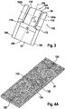
- FIG. 3 Fig. 12 is a side view showing a micromechanical device which does not fall within the scope of the present invention.
- the micromechanical component 100 shown comprises a magnet yoke made of a hard magnet 12, yoke arms 18a and 18b and pole shoes 102a and 102b.
- the pole shoes 102a and 102b are each formed symmetrically to a center plane of the magnetic yoke.
- the median plane which divides the hard magnets 12, the yoke arms 18a and 18b and the pole shoes 102a and 102b is divided into two mutually symmetrical parts, but not in FIG. 3 located.
- the yoke gap 104 lying between the pole shoes 102a and 102b can be divided into two parts by means of a central axis 106, with a first part adjacent to a first pole shoe 102a and a second part adjacent to the second pole shoe 102b.
- the pole shoes 102a and 102b are each arranged at the same distance from the central axis 106 of the yoke gap 104 at their associated Jocharmen 18a and 18b.
- an intermediate frame 30 is arranged with an adjustable actuator.
- FIG. 3 it was distorted to a drawing of the individual components of the intermediate frame 30.
- the actuator of the intermediate frame 30 is about two axes of rotation 108 and 110, which are preferably aligned at an angle of 90 ° to each other, adjustable.
- the adjustment of the actuating element about at least one of the two axes of rotation 108 and 110 takes place by means of a current flow through conductor tracks, which are fixedly arranged on the intermediate frame 30.
- the intermediate frame 30 is arranged in its currentless starting position in the yoke gap 104, that the central axis 106 is in a plane spanned by the two axes of rotation 108 and 110 level. At the same time both axes of rotation 108 and 110 are erected with respect to the central axis 106 at an inclination angle ⁇ 1 or ⁇ 2 not equal to 0 ° and not equal to 90 ° It is also possible to describe the position of the intermediate frame 30 in the yoke gap 104 such that the lateral outer surfaces of the intermediate frame 30 are inclined relative to the contact surfaces of the pole shoes 102a and 102b, which adjoin the yoke gap 104. The intermediate frame 30 is thus obliquely / transversely in the yoke gap 104th
- the corners 112 to 118 of the intermediate frame 30 thus have different distances to their nearest pole piece 102a or 102b.
- the corner 112 is a greater distance from the adjacent first pole piece 102a than the second corner 114a.
- the corner 112 diagonally opposite corner 116 is closer to the second pole piece 102b disordered than the corner 114 diagonally opposite corner 118th
- the intermediate frame 30 can be subdivided into four quadrants by means of the rotary axes 108 and 110, wherein the (not shown) conductor tracks of the quadrants have different average distances to the nearest pole piece 102a or 102b. Accordingly, different mean magnetic field strengths are present in the areas of the tracks of the quadrants. This makes possible the advantageous mode of operation of the micromechanical component 100 described with reference to the preceding example.
- the conductor tracks of the coil device can be designed asymmetrically with respect to at least one of the two axes of rotation.
- a different distance of the conductor tracks from a first axis of rotation may cause at least two different mean magnetic field strengths in the regions of the conductor tracks of the four quadrants even in the case in which the first axis of rotation lies on a central axis of a yoke gap.
- the different distances of the tracks from two squares lying on one side from a first axis of rotation to the first axis of rotation result in a significant variation of the associated torques.
- different torques can be generated on the four quadrants by means of a current flow through a coil.
- the interconnects on the intermediate frame can also be arranged such that the quadrants have a different number of interconnects.
- FIGS. 4A and 4B show a front and a back of an intermediate frame with a designed as a mirror plate actuator
- FIGS. 4A and 4B reproduced intermediate frame 30 can be installed in a Jochapalt a magnetic yoke of one of the two constitusstformen described above. It shows FIG. 4A a front of two cardan suspensions of the mirror plate 124 by means two outer torsion springs 120 and two inner torsion springs 122. In FIG. 4B the back of the gimbal of the intermediate frame 30 is shown. In this case, the attached to the back of the intermediate frame stiffeners 126 can be seen.
- FIG. 5 shows a cross section to illustrate a micromechanical device, which does not fall under the present invention.
- the illustrated micromechanical component 150 comprises a magnetic yoke composed of a hard magnet 12, yoke arms 18a and 18b and pole shoes 102a and 102b.
- the yoke may also have at least one pole piece whose mass distribution is not symmetrical with respect to the median plane (not shown) (see FIG. 1B ).
- an outer frame 152 is arranged within the yoke gap 104 between the two pole pieces 102a and 102b.
- the outer frame 152 is for example part of a holder, which is also associated with the magnetic yoke with the components 12, 18a and 18b and 102a and 102b.
- the outer frame 152 surrounds an intermediate frame 30 with conductor tracks 66 embodied as a coil and an actuating element (not shown).
- the adjustment of the intermediate frame 30 is for example a gimbal-mounted mirror plate, which is adjustable by means of a Lorentz force.
- the at least one outer spring, via which the intermediate frame 30 is connected to the outer frame 152, and the at least one inner spring between the intermediate frame and the adjusting element are in FIG. 5 not shown for the sake of clarity.
- the conductor tracks 66 are preferably formed on the intermediate frame 30 lithographically as a planar coil. It is advantageous if the tracks 66 are formed as high as possible and the distance between the tracks 66 is selected as small as possible. A design of the conductor tracks 66 of several layers is particularly advantageous.
- the intermediate frame 30 can be structured out of a silicon layer.
- frame parts 154 can be formed, which are components of the outer frame 152.
- two cap elements 158 can be attached to the frame part 154 in such a way that both an upper side and an underside of the intermediate frame 30 are covered.
- the outer frame 152 composed of the frame parts 154, the connecting parts 156 and the cap elements 158 may be made airtight.
- the outer frame 152 may be arranged in the hole gap 104, that the axes of rotation of the actuating element are inclined at angles of inclination not equal to 0 ° and not equal to 90 ° to a central axis of the yoke gap 104. Since such an arrangement of the intermediate frame in the yoke gap 104 on the basis of FIG. 3 already described, will not be discussed again here.
- the intermediate frame 30 When the printed conductors 66 are energized, the intermediate frame 30 should experience the torques already described above. It is advantageous if the magnetic field lines 153 of the magnetic field of the magnetic yoke are conducted into the interior of the outer frame 152 such that a sufficiently large field strength of the magnetic field is present in the region of the conductor tracks 66.
- FIG. 6 shows a cross section to illustrate a micromechanical device, which does not fall under the present invention.
- the illustrated micromechanical component 160 has the above-described components 12, 18a and 18b, 102a and 102b and 152.
- the connecting parts 162, with which the cap members 158 are fixed to the frame part 154 formed of a soft magnetic material.
- the magnetic field is concentrated by the use of the permeable connecting portions 162 in the areas of the conductive traces 66.
- the magnetic field is thus conducted well into the interior of the outer frame 152 via the connecting parts 162.
- the soft magnetic material for forming the connection parts 162 may also be mixed with other metal particles.
- FIG. 7 shows a cross section to illustrate a micromechanical device, which does not fall under the present invention.
- the micromechanical component 170 has with respect to the FIG. 5 described embodiment, the supplement that the outer frame 152 is adhered to the Polsehuhen 102a and 102b by means of a permeable adhesive 172.
- the fixing of the outer frame 152 by means of the permeable adhesive 172 in the interior of the yoke coil 104 results in improved stability of the micromechanical component 170.
- the permeable adhesive 172 is arranged on contact surfaces 174 of the pole shoes 102a and 102b which frame the yoke gap 104.
- the permeable adhesive 172 acts in particular analogously to a reduction in the distance between the contact surfaces 174 and the outer frame 152. This is illustrated pictorially via the magnetic field lines 176.
- the permeable adhesive 172 may be made permeable by a high level of metal particles, such as iron particles.
- the connecting parts 156 by means of which the Kappsnimplantation 158 are attached to the frame part 154, are also mixed with particles of a conductive material and / or formed from a permeable adhesive.
- the use of the permeable adhesive 172 acts to reduce the distance between the coil means 66 and the contact surfaces 174. More specifically, a minimum distance between the coil means 66 and the contact surfaces 174 approaches zero.
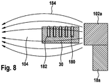
- FIG. 8 shows a partial section of a cross section for illustrating a micromechanical device, which does not fall under the present invention.
- FIG. 8 a yoke is shown schematically by means of a Jocharms 18a and attached to the Jocharm 18a pole piece 102a. Between the sketched pole shoe 102a and a pole thrust, not shown, there is a yoke gap 104 with a magnetic field represented by the magnetic field lines 184. In the interior of the yoke gap 104, an intermediate frame 30 with an adjustable (not outlined) actuator is arranged. The intermediate frame 30 may correspond to the embodiment described above.
- the pole shoes 102a have a mass distribution which is symmetrical to a median plane of the magnetic yoke. Instead of the pole pieces 102a. may be attached to the yoke arms 18a and pole shoes whose mass distribution is not symmetrical with respect to the median plane of the Magnctjochs (see example of FIG. 1B ).
- the in FIG. 8 schematically reproduced intermediate frame 30 comprises conductor tracks 180 which are arranged in trenches 182.
- the flow area of the tracks 118 for the magnetic field lines 184 of the magnetic field is thus comparatively large.
- the interconnects 118 formed in the trenches 182 therefore have a comparatively high aspect ratio. This high aspect ratio acts similarly to a reduced distance between the tracks 180 and the pole pieces 102a. This results in a high current carrying capacity and a small distance to the magnetic field.
- additional conductor tracks can also be arranged on the rear side of the adjusting element.
- the field lines 184 can be guided in a more targeted manner to the printed conductors 180 formed in or outside of the trenches 182.
- FIG. 9 shows a cross section through an outer frame to illustrate a micromechanical device, which does not fall under the present invention.
- micromechanical component 190 may be a magnetic yoke according to the FIGS. 1A, 1B . 2A . 2 B . 3 and 5 to 7 have described embodiments.
- the in FIG. 9 illustrated outer frame 192 comprises a frame part 194, which is structured out together with the intermediate frame 30 of a silicon and / or glass layer.
- a force applied to an upper side of the outer frame member 194 connecting part 196 an upper cap 198 is attached to the frame part 194.
- a lower cap 200 is attached directly to an underside of the frame member 194.
- the composite of the components 194 to 200 outer frame 192 may surround the intermediate frame, the control element, not shown, and the Porterbalmen 66 airtight. This ensures good protection for the components 30 and 66 inside the outer frame 192.
- the patterning out of the intermediate frame 30 and of the frame part 194 from the common silicon and / or glass layer is preferably carried out by etching a first trench 202 starting from a front side of the intermediate frame 30 and etching a second trench 204 starting from one Bottom of the intermediate frame 30.
- a more stable frame part 194 can be achieved if the etching of the second etching trench 204 is performed from the bottom with an undercut.
- the frame part 194 thus has on its upper side a first diameter d1 and on its underside a second diameter d2, wherein the second diameter d2 is greater than the first diameter d1.
- a diameter d1 or d2 is understood to mean a width through a compact section of the frame part 194.
- the frame part 194 formed at a small distance from the intermediate frame 30 is made comparatively thin in its upper regions with the diameter d1.
- the thinning acts according to a reduction in the distance between the tracks and the pole pieces (not shown).
- the base of the frame part with the larger second diameter d2 carries in contrast to the mechanical stability of the frame part 194, and thus to the mechanical stability of the outer frame 192 at.
- the frame part 194 thus has a curvature adjacent to the inner volume of the outer frame 192. This shape of the frame part 194 allows good mobility of the intermediate frame 30 and the control element, not shown.
- micromechanical components described in the upper sections can be produced with an extension of about 5 to 10 mm. This makes it possible to install the micromechanical components described in a small micro device, such as a cell phone.
Landscapes
- Physics & Mathematics (AREA)
- Electromagnetism (AREA)
- Engineering & Computer Science (AREA)
- Power Engineering (AREA)
- General Physics & Mathematics (AREA)
- Optics & Photonics (AREA)
- Micromachines (AREA)
- Reciprocating, Oscillating Or Vibrating Motors (AREA)
Claims (7)
- Culasse d'aimant (10) comportant :un aimant (12) ayant une direction de magnétisation (14), sur lequel une première branche de culasse (18a) et une deuxième branche de culasse (18b) sont disposées de manière à ce que l'aimant (12) et les deux branches de culasse (18a, 18b) englobent un espace intermédiaire de la culasse (20) s'étendant d'une face avant à une face arrière de la culasse d'aimant ; etune première pièce polaire (22a) disposée sur la première branche de culasse (18a) et une deuxième pièce polaire (22b) disposée sur la deuxième branche de culasse (18b), entre lesquelles se trouve un entrefer de culasse (24) ;dans lequel il est possible de définir un plan médian (32) qui est orienté parallèlement à la direction de magnétisation (14) et passe par l'aimant (12) et les deux branches de culasse (18a, 18b),caractérisé en ce que les pièces polaires (22a, 22b) sont respectivement réalisées de manière à ce que leur distribution de masse ne présente pas de symétrie par rapport au plan médian (32), la première pièce polaire (22a) présentant une première largeur (b1) au niveau d'une première extrémité (40a) sur la face avant de la culasse d'aimant (10), parallèlement à la direction de magnétisation (14) de l'aimant (12) et présentant une deuxième largeur (b2) différente de la première largeur (b1) au niveau d'une deuxième extrémité (42a) opposée à la première extrémité (40a) sur la face arrière de la culasse d'aimant (10), parallèlement à la direction de magnétisation (14) de l'aimant (12).
- Culasse d'aimant (10) selon la revendication 1, dans laquelle le plan médian (32) divise la première pièce polaire (22a) en une première moitié (34a) et en une deuxième moitié (36a), et dans laquelle la première moitié (34a) présente, par rapport à la deuxième moitié (36a), une masse supplémentaire (38a) qui fait saillie dans l'entrefer de culasse (34).
- Culasse d'aimant (10) selon la revendication 2, dans laquelle le plan médian (32) divise les deux pièces polaires (22a, 22b) respectivement en une première moitié (34a, 34b) comportant la masse supplémentaire (38a, 38b) et en une deuxième moitié (36a, 36b) ne comportant pas la masse supplémentaire (38a, 38b).
- Culasse d'aimant (10) selon la revendication 12 ou 3, dans laquelle la masse supplémentaire (38a, 38b) s'étend dans une direction perpendiculaire à une largeur (bmax) de l'entrefer de culasse (24), le long de la totalité de la première moitié (34a, 34b).
- Composant micromécanique, comportant :une culasse d'aimant (10) selon l'une quelconque des revendications 1 à 4 ;un cadre intermédiaire (30) disposé dans l'entrefer de culasse (24, 104) au moyen d'au moins un premier ressort (51) orienté le long d'un premier axe (52, 102), lequel cadre intermédiaire encadre un élément de réglage (60) qui est relié au cadre intermédiaire (30) par l'intermédiaire d'au moins un deuxième ressort (62) orienté le long d'un deuxième axe (64, 110) ; etdes pistes conductrices (66) disposées de manière fixe sur le cadre intermédiaire (30), lesquelles pistes conductrices sont réalisées sous la forme de bobines ;dans lequel le cadre intermédiaire (30) peut être divisé au moyen du premier axe (52, 108) et du deuxième axe (64, 110) en quatre quadrants (I à IV), parmi lesquels des premier et deuxième quadrants (I, II) sont disposés de manière adjacente à la première pièce polaire (22a, 102a) et des troisième et quatrième quadrants (III, IV) sont disposés de manière adjacente à la deuxième pièce polaire (22b, 102b),et dans lequel le cadre intermédiaire (30) est disposé dans l'entrefer de culasse (24, 104) et les pistes conductrices (66) sont disposées sur le cadre intermédiaire (30), de manière à ce qu'une distance moyenne entre les pistes conductrices (66) du premier quadrant (I) et la première pièce polaire (22a, 102a) soit inférieure à une distance moyenne entre les pistes conductrices (66) du deuxième quadrant (II) et la première pièce polaire (22a, 102a).
- Procédé de fabrication d'une culasse d'aimant (10) selon la revendication 1, comportant les étapes consistant à :disposer un aimant (12) ayant une direction de magnétisation (14) entre une première branche de culasse (18a) et une deuxième branche de culasse (18b), de manière à ce que l'aimant (12) et les deux branches de culasse (18a, 18b) englobent un espace intermédiaire de culasse (20) s'étendant d'une face avant à une face arrière de la culasse d'aimant (10) ;disposer une première pièce polaire (22a) sur la première branche de culasse (18a) ; etdisposer une deuxième pièce polaire (22b) sur la deuxième branche de culasse (18b) de manière à ce qu'un entrefer de culasse (24) soit présent entre la première pièce polaire (22a) et la deuxième pièce polaire (22b) ;
caractérisé par l'étape selon laquelleles pièces polaires (22a, 22b) sont respectivement disposées de manière à ce que leur répartition de masse par rapport à un plan médian (32), qui est orienté parallèlement à la direction de magnétisation (14) et passe par l'aimant (12) et les deux branches de culasse (18a, 18b), ne présente aucune symétrie, la première pièce polaire (22a) étant réalisée de manière à ce que la première pièce polaire (22a) présente une première largeur (b1) au niveau d'une première extrémité (40a) sur la face avant de la culasse d'aimant (10), parallèlement à la direction de magnétisation (14) de l'aimant (12), et présente une deuxième largeur (b2), différente de la première largeur (b1), au niveau d'une deuxième extrémité (42a) opposée à la première extrémité (40a) sur la face arrière de la culasse d'aimant (10), parallèlement à la direction de magnétisation (14) de l'aimant (12). - Procédé de fabrication destiné à un composant micromécanique (100) selon la revendication 5, comportant les étapes consistant à :fabriquer une culasse d'aimant (10) conformément au procédé de fabrication selon la revendication 6 ;disposer un cadre intermédiaire (30) dans l'entrefer de culasse (24, 104) au moyen d'au moins un premier ressort (51) orienté le long d'un premier axe (52, 108) et d'un élément de réglage (60) dans une ouverture (58) du cadre intermédiaire (30), dans lequel l'élément de réglage (60) est relié au cadre intermédiaire (30) par l'intermédiaire d'au moins un deuxième ressort (62) orienté le long d'un deuxième axe (64, 110) ; etdisposer de manière fixe des pistes conductrices (66) sous la forme de bobines sur le cadre intermédiaire (30) ;dans lequel le cadre intermédiaire (30) est disposé dans l'entrefer de culasse (24, 104) et les pistes conductrices (66) sont disposées sur le cadre intermédiaire (30), de manière à ce que, par subdivision du cadre intermédiaire (30) au moyen du premier axe (52, 108) et du deuxième axe (64, 110) en quatre quadrants (I à IV), parmi lesquels des premier et deuxième quadrants (I, II) sont disposés de manière adjacente à la première pièce polaire (22a, 102a) et des troisième et quatrième quadrants (III, IV) sont disposés de manière adjacente à la deuxième pièce polaire (22b, 102b), une distance moyenne entre les pistes conductrices (66) du premier quadrant (I) et la première pièce polaire (22a, 102a) soit inférieure à une distance moyenne entre les pistes conductrices (66) du deuxième quadrant (II) et la première pièce polaire (22a, 102a).
Applications Claiming Priority (2)
| Application Number | Priority Date | Filing Date | Title |
|---|---|---|---|
| DE102008042346A DE102008042346A1 (de) | 2008-09-25 | 2008-09-25 | Magnetjoch, mikromechanisches Bauteil und Herstellungsverfahren für ein Magnetjoch und ein mikromechanisches Bauteil |
| PCT/EP2009/060020 WO2010034551A1 (fr) | 2008-09-25 | 2009-08-03 | Culasse d’aimant, composant micromécanique et procédé de fabrication pour une culasse d’aimant et un composant micromécanique |
Publications (2)
| Publication Number | Publication Date |
|---|---|
| EP2332155A1 EP2332155A1 (fr) | 2011-06-15 |
| EP2332155B1 true EP2332155B1 (fr) | 2017-05-17 |
Family
ID=41168690
Family Applications (1)
| Application Number | Title | Priority Date | Filing Date |
|---|---|---|---|
| EP09781413.1A Not-in-force EP2332155B1 (fr) | 2008-09-25 | 2009-08-03 | Culasse d aimant, composant micromecanique et procede de fabrication pour une culasse d' aimant et un composant micromecanique |
Country Status (4)
| Country | Link |
|---|---|
| US (1) | US20110199172A1 (fr) |
| EP (1) | EP2332155B1 (fr) |
| DE (1) | DE102008042346A1 (fr) |
| WO (1) | WO2010034551A1 (fr) |
Families Citing this family (22)
| Publication number | Priority date | Publication date | Assignee | Title |
|---|---|---|---|---|
| US8305672B2 (en) | 2010-02-23 | 2012-11-06 | Microvision, Inc. | Magnetically actuated system |
| DE102010062591A1 (de) | 2010-12-08 | 2012-06-14 | Robert Bosch Gmbh | Magnetischer Aktor |
| WO2013168267A1 (fr) * | 2012-05-10 | 2013-11-14 | パイオニア株式会社 | Dispositif d'entraînement |
| WO2013168275A1 (fr) * | 2012-05-10 | 2013-11-14 | パイオニア株式会社 | Dispositif d'entraînement |
| WO2013168268A1 (fr) * | 2012-05-10 | 2013-11-14 | パイオニア株式会社 | Dispositif d'entraînement |
| JP6014234B2 (ja) * | 2012-05-10 | 2016-10-25 | パイオニア株式会社 | 駆動装置 |
| WO2013168271A1 (fr) * | 2012-05-10 | 2013-11-14 | パイオニア株式会社 | Dispositif d'entraînement |
| WO2013168266A1 (fr) * | 2012-05-10 | 2013-11-14 | パイオニア株式会社 | Dispositif d'entraînement |
| JPWO2013168485A1 (ja) * | 2012-05-10 | 2016-01-07 | パイオニア株式会社 | 駆動装置 |
| WO2013168270A1 (fr) * | 2012-05-10 | 2013-11-14 | パイオニア株式会社 | Dispositif d'entraînement |
| WO2013168264A1 (fr) | 2012-05-10 | 2013-11-14 | パイオニア株式会社 | Dispositif d'entraînement |
| WO2013168274A1 (fr) * | 2012-05-10 | 2013-11-14 | パイオニア株式会社 | Dispositif d'entraînement |
| WO2013168265A1 (fr) * | 2012-05-10 | 2013-11-14 | パイオニア株式会社 | Dispositif d'entraînement |
| WO2013168272A1 (fr) * | 2012-05-10 | 2013-11-14 | パイオニア株式会社 | Dispositif d'entraînement |
| WO2013168269A1 (fr) * | 2012-05-10 | 2013-11-14 | パイオニア株式会社 | Dispositif d'entraînement |
| WO2013168273A1 (fr) * | 2012-05-10 | 2013-11-14 | パイオニア株式会社 | Dispositif d'entraînement |
| WO2014020769A1 (fr) * | 2012-08-03 | 2014-02-06 | パイオニア株式会社 | Unité de commande |
| JP2016512654A (ja) * | 2013-03-12 | 2016-04-28 | コーニンクレッカ フィリップス エヌ ヴェKoninklijke Philips N.V. | バイオセンサ用u字形磁石 |
| WO2014192123A1 (fr) * | 2013-05-30 | 2014-12-04 | パイオニア株式会社 | Structure de corps en acier |
| JP6929006B2 (ja) * | 2016-07-01 | 2021-09-01 | 日本信号株式会社 | 駆動装置 |
| JP6935254B2 (ja) * | 2017-07-10 | 2021-09-15 | 日本信号株式会社 | 駆動装置 |
| CN112967857B (zh) * | 2020-04-17 | 2023-12-15 | 北京中科三环高技术股份有限公司 | 永磁装置 |
Family Cites Families (21)
| Publication number | Priority date | Publication date | Assignee | Title |
|---|---|---|---|---|
| US4827235A (en) * | 1986-07-18 | 1989-05-02 | Kabushiki Kaisha Toshiba | Magnetic field generator useful for a magnetic resonance imaging instrument |
| JP3003429B2 (ja) * | 1992-10-08 | 2000-01-31 | 富士電機株式会社 | ねじり振動子および光偏向子 |
| US5319339A (en) * | 1993-03-08 | 1994-06-07 | The United States Of America As Represented By The Secretary Of The Army | Tubular structure having transverse magnetic field with gradient |
| US5495222A (en) * | 1994-04-15 | 1996-02-27 | New York University | Open permanent magnet structure for generating highly uniform field |
| JP2987750B2 (ja) | 1995-05-26 | 1999-12-06 | 日本信号株式会社 | プレーナ型電磁アクチュエータ |
| WO1996039643A1 (fr) * | 1995-06-05 | 1996-12-12 | Nihon Shingo Kabushiki Kaisha | Actionneur electromagnetique |
| US5635889A (en) * | 1995-09-21 | 1997-06-03 | Permag Corporation | Dipole permanent magnet structure |
| US5886609A (en) * | 1997-10-22 | 1999-03-23 | Dexter Magnetic Technologies, Inc. | Single dipole permanent magnet structure with linear gradient magnetic field intensity |
| WO1999036825A1 (fr) * | 1998-01-16 | 1999-07-22 | Board Of Supervisors Of Louisiana State University And Agricultural And Mechanical College | Microscanner a induction |
| EP0998016B1 (fr) * | 1998-10-30 | 2007-08-29 | International Business Machines Corporation | Système magnétique de balayage ou de positionement avec au moins deux degrés de libertés |
| AU2001286745A1 (en) * | 2000-08-27 | 2002-03-13 | Corning Intellisense Corporation | Magnetically actuated micro-electro-mechanical apparatus and method of manufacture |
| US6388789B1 (en) * | 2000-09-19 | 2002-05-14 | The Charles Stark Draper Laboratory, Inc. | Multi-axis magnetically actuated device |
| US6784771B1 (en) * | 2001-07-24 | 2004-08-31 | New Peregrine, Inc. | MEMS optical mirror array |
| JP4729289B2 (ja) * | 2003-12-04 | 2011-07-20 | オリンパス株式会社 | 光偏向器 |
| US7485485B2 (en) | 2004-02-09 | 2009-02-03 | Microvision, Inc. | Method and apparatus for making a MEMS scanner |
| US7442918B2 (en) * | 2004-05-14 | 2008-10-28 | Microvision, Inc. | MEMS device having simplified drive |
| FR2880729B1 (fr) * | 2005-01-10 | 2009-02-27 | Schneider Electric Ind Sas | Microsysteme a commande electromagnetique |
| KR100738114B1 (ko) * | 2006-05-18 | 2007-07-12 | 삼성전자주식회사 | 액츄에이터 및 이차원 스캐너 |
| KR100911144B1 (ko) * | 2007-03-27 | 2009-08-06 | 삼성전자주식회사 | 2축구동 전자기 액추에이터 |
| US8159320B2 (en) * | 2009-09-14 | 2012-04-17 | Meichun Ruan | Latching micro-magnetic relay and method of operating same |
| US8378769B2 (en) * | 2010-08-16 | 2013-02-19 | Cooltech Applications, S.A.S. | Magnetic field generator for a magnetocaloric thermal appliance and process for assembling such generator |
-
2008
- 2008-09-25 DE DE102008042346A patent/DE102008042346A1/de not_active Withdrawn
-
2009
- 2009-08-03 EP EP09781413.1A patent/EP2332155B1/fr not_active Not-in-force
- 2009-08-03 WO PCT/EP2009/060020 patent/WO2010034551A1/fr not_active Ceased
- 2009-08-03 US US12/737,894 patent/US20110199172A1/en not_active Abandoned
Non-Patent Citations (1)
| Title |
|---|
| None * |
Also Published As
| Publication number | Publication date |
|---|---|
| WO2010034551A1 (fr) | 2010-04-01 |
| US20110199172A1 (en) | 2011-08-18 |
| EP2332155A1 (fr) | 2011-06-15 |
| DE102008042346A1 (de) | 2010-04-01 |
Similar Documents
| Publication | Publication Date | Title |
|---|---|---|
| EP2332155B1 (fr) | Culasse d aimant, composant micromecanique et procede de fabrication pour une culasse d' aimant et un composant micromecanique | |
| EP3382412B1 (fr) | Ensemble d'aimants permanents pour appareils rm pourvus d'ensembles d'anneaux latéraux montés coulissants, rotatifs | |
| DE69511727T2 (de) | Elektromagnetischer krafterzeuger | |
| DE4334267C2 (de) | Torsionsvibrator | |
| DE69613061T2 (de) | Magnetkreisanordnung mit einander gegenüberliegenden Permanentmagneten | |
| EP0127741B1 (fr) | Système de suspension pour un véhicule automobile | |
| DE102012208117B4 (de) | Mikromechanisches Bauteil | |
| DE19963382A1 (de) | Mikrospiegel | |
| DE3333955A1 (de) | Permanentmagnet-mehrpolgebilde mit einstellbarer staerke | |
| EP3420569B1 (fr) | Actionneur à reluctance | |
| DE102012202998A1 (de) | Elektromagnetisches Federungssytem | |
| EP3924295B1 (fr) | Mems et procédé pour sa fabrication | |
| DE102008001896B4 (de) | Mikromechanisches Bauteil und Herstellungsverfahren für ein mikromechanisches Bauteil | |
| EP4115434B1 (fr) | Actionneur électromagnetique | |
| EP3627673B1 (fr) | Pièce secondaire segmenté pour un moteur linéaire | |
| DE4204070C1 (fr) | ||
| DE102006009311A1 (de) | Bremsvorrichtung für Linearmotor und Verfahren zur Positionierung eines beweglichen Abschnitts des Linearmotors | |
| EP0541902A1 (fr) | Support élastique | |
| DE102008001232A1 (de) | Elektrodenkamm, mikromechanisches Bauteil und Herstellungsverfahren für einen Elektrodenkamm und für ein mikromechanisches Bauteil | |
| DE19838132B4 (de) | Synchronlinearmotor | |
| DE19723515C2 (de) | Elastische Anordnung zum Führen von zwei elastisch verbundenen Bauteilen in einer Bewegungsrichtung | |
| DE102009000599A1 (de) | Elektrostatischer Antrieb, Verfahren zum Betreiben eines mikromechanischen Bauteils mit einem elektrostatischen Antrieb und Herstellungsverfahren für einen elektrostatischen Antrieb | |
| DE102008001238A1 (de) | Mikromechanisches Bauteil, Verfahren zum Betreiben eines mikromechanischen Bauteils und Herstellungsverfahren für ein mikromechanisches Bauteil | |
| EP4211707A2 (fr) | Dispositif de réglage, système de réglage et produit-programme d'ordinateur | |
| EP4336577B1 (fr) | Ensemble actionneur et procédé de fonctionnement |
Legal Events
| Date | Code | Title | Description |
|---|---|---|---|
| PUAI | Public reference made under article 153(3) epc to a published international application that has entered the european phase |
Free format text: ORIGINAL CODE: 0009012 |
|
| 17P | Request for examination filed |
Effective date: 20110426 |
|
| AK | Designated contracting states |
Kind code of ref document: A1 Designated state(s): AT BE BG CH CY CZ DE DK EE ES FI FR GB GR HR HU IE IS IT LI LT LU LV MC MK MT NL NO PL PT RO SE SI SK SM TR |
|
| AX | Request for extension of the european patent |
Extension state: AL BA RS |
|
| DAX | Request for extension of the european patent (deleted) | ||
| GRAP | Despatch of communication of intention to grant a patent |
Free format text: ORIGINAL CODE: EPIDOSNIGR1 |
|
| INTG | Intention to grant announced |
Effective date: 20170222 |
|
| GRAS | Grant fee paid |
Free format text: ORIGINAL CODE: EPIDOSNIGR3 |
|
| GRAA | (expected) grant |
Free format text: ORIGINAL CODE: 0009210 |
|
| AK | Designated contracting states |
Kind code of ref document: B1 Designated state(s): AT BE BG CH CY CZ DE DK EE ES FI FR GB GR HR HU IE IS IT LI LT LU LV MC MK MT NL NO PL PT RO SE SI SK SM TR |
|
| REG | Reference to a national code |
Ref country code: GB Ref legal event code: FG4D Free format text: NOT ENGLISH |
|
| REG | Reference to a national code |
Ref country code: CH Ref legal event code: EP |
|
| REG | Reference to a national code |
Ref country code: IE Ref legal event code: FG4D Free format text: LANGUAGE OF EP DOCUMENT: GERMAN |
|
| REG | Reference to a national code |
Ref country code: AT Ref legal event code: REF Ref document number: 895132 Country of ref document: AT Kind code of ref document: T Effective date: 20170615 |
|
| REG | Reference to a national code |
Ref country code: DE Ref legal event code: R096 Ref document number: 502009013992 Country of ref document: DE |
|
| REG | Reference to a national code |
Ref country code: FR Ref legal event code: PLFP Year of fee payment: 9 |
|
| REG | Reference to a national code |
Ref country code: NL Ref legal event code: MP Effective date: 20170517 |
|
| REG | Reference to a national code |
Ref country code: LT Ref legal event code: MG4D |
|
| PG25 | Lapsed in a contracting state [announced via postgrant information from national office to epo] |
Ref country code: FI Free format text: LAPSE BECAUSE OF FAILURE TO SUBMIT A TRANSLATION OF THE DESCRIPTION OR TO PAY THE FEE WITHIN THE PRESCRIBED TIME-LIMIT Effective date: 20170517 Ref country code: ES Free format text: LAPSE BECAUSE OF FAILURE TO SUBMIT A TRANSLATION OF THE DESCRIPTION OR TO PAY THE FEE WITHIN THE PRESCRIBED TIME-LIMIT Effective date: 20170517 Ref country code: GR Free format text: LAPSE BECAUSE OF FAILURE TO SUBMIT A TRANSLATION OF THE DESCRIPTION OR TO PAY THE FEE WITHIN THE PRESCRIBED TIME-LIMIT Effective date: 20170818 Ref country code: LT Free format text: LAPSE BECAUSE OF FAILURE TO SUBMIT A TRANSLATION OF THE DESCRIPTION OR TO PAY THE FEE WITHIN THE PRESCRIBED TIME-LIMIT Effective date: 20170517 Ref country code: HR Free format text: LAPSE BECAUSE OF FAILURE TO SUBMIT A TRANSLATION OF THE DESCRIPTION OR TO PAY THE FEE WITHIN THE PRESCRIBED TIME-LIMIT Effective date: 20170517 Ref country code: NO Free format text: LAPSE BECAUSE OF FAILURE TO SUBMIT A TRANSLATION OF THE DESCRIPTION OR TO PAY THE FEE WITHIN THE PRESCRIBED TIME-LIMIT Effective date: 20170817 |
|
| PG25 | Lapsed in a contracting state [announced via postgrant information from national office to epo] |
Ref country code: SE Free format text: LAPSE BECAUSE OF FAILURE TO SUBMIT A TRANSLATION OF THE DESCRIPTION OR TO PAY THE FEE WITHIN THE PRESCRIBED TIME-LIMIT Effective date: 20170517 Ref country code: IS Free format text: LAPSE BECAUSE OF FAILURE TO SUBMIT A TRANSLATION OF THE DESCRIPTION OR TO PAY THE FEE WITHIN THE PRESCRIBED TIME-LIMIT Effective date: 20170917 Ref country code: PL Free format text: LAPSE BECAUSE OF FAILURE TO SUBMIT A TRANSLATION OF THE DESCRIPTION OR TO PAY THE FEE WITHIN THE PRESCRIBED TIME-LIMIT Effective date: 20170517 Ref country code: BG Free format text: LAPSE BECAUSE OF FAILURE TO SUBMIT A TRANSLATION OF THE DESCRIPTION OR TO PAY THE FEE WITHIN THE PRESCRIBED TIME-LIMIT Effective date: 20170817 Ref country code: NL Free format text: LAPSE BECAUSE OF FAILURE TO SUBMIT A TRANSLATION OF THE DESCRIPTION OR TO PAY THE FEE WITHIN THE PRESCRIBED TIME-LIMIT Effective date: 20170517 Ref country code: LV Free format text: LAPSE BECAUSE OF FAILURE TO SUBMIT A TRANSLATION OF THE DESCRIPTION OR TO PAY THE FEE WITHIN THE PRESCRIBED TIME-LIMIT Effective date: 20170517 |
|
| PG25 | Lapsed in a contracting state [announced via postgrant information from national office to epo] |
Ref country code: DK Free format text: LAPSE BECAUSE OF FAILURE TO SUBMIT A TRANSLATION OF THE DESCRIPTION OR TO PAY THE FEE WITHIN THE PRESCRIBED TIME-LIMIT Effective date: 20170517 Ref country code: CZ Free format text: LAPSE BECAUSE OF FAILURE TO SUBMIT A TRANSLATION OF THE DESCRIPTION OR TO PAY THE FEE WITHIN THE PRESCRIBED TIME-LIMIT Effective date: 20170517 Ref country code: EE Free format text: LAPSE BECAUSE OF FAILURE TO SUBMIT A TRANSLATION OF THE DESCRIPTION OR TO PAY THE FEE WITHIN THE PRESCRIBED TIME-LIMIT Effective date: 20170517 Ref country code: RO Free format text: LAPSE BECAUSE OF FAILURE TO SUBMIT A TRANSLATION OF THE DESCRIPTION OR TO PAY THE FEE WITHIN THE PRESCRIBED TIME-LIMIT Effective date: 20170517 Ref country code: SK Free format text: LAPSE BECAUSE OF FAILURE TO SUBMIT A TRANSLATION OF THE DESCRIPTION OR TO PAY THE FEE WITHIN THE PRESCRIBED TIME-LIMIT Effective date: 20170517 |
|
| REG | Reference to a national code |
Ref country code: DE Ref legal event code: R097 Ref document number: 502009013992 Country of ref document: DE |
|
| PG25 | Lapsed in a contracting state [announced via postgrant information from national office to epo] |
Ref country code: SM Free format text: LAPSE BECAUSE OF FAILURE TO SUBMIT A TRANSLATION OF THE DESCRIPTION OR TO PAY THE FEE WITHIN THE PRESCRIBED TIME-LIMIT Effective date: 20170517 |
|
| PLBE | No opposition filed within time limit |
Free format text: ORIGINAL CODE: 0009261 |
|
| STAA | Information on the status of an ep patent application or granted ep patent |
Free format text: STATUS: NO OPPOSITION FILED WITHIN TIME LIMIT |
|
| REG | Reference to a national code |
Ref country code: CH Ref legal event code: PL |
|
| PG25 | Lapsed in a contracting state [announced via postgrant information from national office to epo] |
Ref country code: MC Free format text: LAPSE BECAUSE OF FAILURE TO SUBMIT A TRANSLATION OF THE DESCRIPTION OR TO PAY THE FEE WITHIN THE PRESCRIBED TIME-LIMIT Effective date: 20170517 |
|
| 26N | No opposition filed |
Effective date: 20180220 |
|
| PG25 | Lapsed in a contracting state [announced via postgrant information from national office to epo] |
Ref country code: CH Free format text: LAPSE BECAUSE OF NON-PAYMENT OF DUE FEES Effective date: 20170831 Ref country code: LI Free format text: LAPSE BECAUSE OF NON-PAYMENT OF DUE FEES Effective date: 20170831 |
|
| REG | Reference to a national code |
Ref country code: IE Ref legal event code: MM4A |
|
| PG25 | Lapsed in a contracting state [announced via postgrant information from national office to epo] |
Ref country code: SI Free format text: LAPSE BECAUSE OF FAILURE TO SUBMIT A TRANSLATION OF THE DESCRIPTION OR TO PAY THE FEE WITHIN THE PRESCRIBED TIME-LIMIT Effective date: 20170517 |
|
| REG | Reference to a national code |
Ref country code: BE Ref legal event code: MM Effective date: 20170831 |
|
| PG25 | Lapsed in a contracting state [announced via postgrant information from national office to epo] |
Ref country code: LU Free format text: LAPSE BECAUSE OF NON-PAYMENT OF DUE FEES Effective date: 20170803 |
|
| PG25 | Lapsed in a contracting state [announced via postgrant information from national office to epo] |
Ref country code: IE Free format text: LAPSE BECAUSE OF NON-PAYMENT OF DUE FEES Effective date: 20170803 |
|
| REG | Reference to a national code |
Ref country code: FR Ref legal event code: PLFP Year of fee payment: 10 |
|
| PG25 | Lapsed in a contracting state [announced via postgrant information from national office to epo] |
Ref country code: BE Free format text: LAPSE BECAUSE OF NON-PAYMENT OF DUE FEES Effective date: 20170831 |
|
| PG25 | Lapsed in a contracting state [announced via postgrant information from national office to epo] |
Ref country code: MT Free format text: LAPSE BECAUSE OF FAILURE TO SUBMIT A TRANSLATION OF THE DESCRIPTION OR TO PAY THE FEE WITHIN THE PRESCRIBED TIME-LIMIT Effective date: 20170517 |
|
| REG | Reference to a national code |
Ref country code: AT Ref legal event code: MM01 Ref document number: 895132 Country of ref document: AT Kind code of ref document: T Effective date: 20170803 |
|
| PGFP | Annual fee paid to national office [announced via postgrant information from national office to epo] |
Ref country code: IT Payment date: 20180823 Year of fee payment: 10 |
|
| PG25 | Lapsed in a contracting state [announced via postgrant information from national office to epo] |
Ref country code: AT Free format text: LAPSE BECAUSE OF NON-PAYMENT OF DUE FEES Effective date: 20170803 |
|
| PG25 | Lapsed in a contracting state [announced via postgrant information from national office to epo] |
Ref country code: HU Free format text: LAPSE BECAUSE OF FAILURE TO SUBMIT A TRANSLATION OF THE DESCRIPTION OR TO PAY THE FEE WITHIN THE PRESCRIBED TIME-LIMIT; INVALID AB INITIO Effective date: 20090803 |
|
| PG25 | Lapsed in a contracting state [announced via postgrant information from national office to epo] |
Ref country code: CY Free format text: LAPSE BECAUSE OF NON-PAYMENT OF DUE FEES Effective date: 20170517 |
|
| PG25 | Lapsed in a contracting state [announced via postgrant information from national office to epo] |
Ref country code: MK Free format text: LAPSE BECAUSE OF FAILURE TO SUBMIT A TRANSLATION OF THE DESCRIPTION OR TO PAY THE FEE WITHIN THE PRESCRIBED TIME-LIMIT Effective date: 20170517 |
|
| PG25 | Lapsed in a contracting state [announced via postgrant information from national office to epo] |
Ref country code: TR Free format text: LAPSE BECAUSE OF FAILURE TO SUBMIT A TRANSLATION OF THE DESCRIPTION OR TO PAY THE FEE WITHIN THE PRESCRIBED TIME-LIMIT Effective date: 20170517 |
|
| PG25 | Lapsed in a contracting state [announced via postgrant information from national office to epo] |
Ref country code: PT Free format text: LAPSE BECAUSE OF FAILURE TO SUBMIT A TRANSLATION OF THE DESCRIPTION OR TO PAY THE FEE WITHIN THE PRESCRIBED TIME-LIMIT Effective date: 20170517 |
|
| PG25 | Lapsed in a contracting state [announced via postgrant information from national office to epo] |
Ref country code: IT Free format text: LAPSE BECAUSE OF NON-PAYMENT OF DUE FEES Effective date: 20190803 |
|
| PGFP | Annual fee paid to national office [announced via postgrant information from national office to epo] |
Ref country code: FR Payment date: 20210823 Year of fee payment: 13 |
|
| PGFP | Annual fee paid to national office [announced via postgrant information from national office to epo] |
Ref country code: GB Payment date: 20210824 Year of fee payment: 13 |
|
| PGFP | Annual fee paid to national office [announced via postgrant information from national office to epo] |
Ref country code: DE Payment date: 20221025 Year of fee payment: 14 |
|
| GBPC | Gb: european patent ceased through non-payment of renewal fee |
Effective date: 20220803 |
|
| PG25 | Lapsed in a contracting state [announced via postgrant information from national office to epo] |
Ref country code: FR Free format text: LAPSE BECAUSE OF NON-PAYMENT OF DUE FEES Effective date: 20220831 |
|
| PG25 | Lapsed in a contracting state [announced via postgrant information from national office to epo] |
Ref country code: GB Free format text: LAPSE BECAUSE OF NON-PAYMENT OF DUE FEES Effective date: 20220803 |
|
| REG | Reference to a national code |
Ref country code: DE Ref legal event code: R119 Ref document number: 502009013992 Country of ref document: DE |
|
| PG25 | Lapsed in a contracting state [announced via postgrant information from national office to epo] |
Ref country code: DE Free format text: LAPSE BECAUSE OF NON-PAYMENT OF DUE FEES Effective date: 20240301 |