EP2332276B1 - Passive optische netzwerke - Google Patents
Passive optische netzwerke Download PDFInfo
- Publication number
- EP2332276B1 EP2332276B1 EP08803641A EP08803641A EP2332276B1 EP 2332276 B1 EP2332276 B1 EP 2332276B1 EP 08803641 A EP08803641 A EP 08803641A EP 08803641 A EP08803641 A EP 08803641A EP 2332276 B1 EP2332276 B1 EP 2332276B1
- Authority
- EP
- European Patent Office
- Prior art keywords
- data signal
- optical
- optical network
- return
- pulse
- Prior art date
- Legal status (The legal status is an assumption and is not a legal conclusion. Google has not performed a legal analysis and makes no representation as to the accuracy of the status listed.)
- Not-in-force
Links
- 230000003287 optical effect Effects 0.000 title claims abstract description 254
- 238000011144 upstream manufacturing Methods 0.000 claims abstract description 97
- 238000000034 method Methods 0.000 claims abstract description 30
- 239000004065 semiconductor Substances 0.000 claims description 32
- 230000003321 amplification Effects 0.000 claims description 4
- 238000003199 nucleic acid amplification method Methods 0.000 claims description 4
- 239000000835 fiber Substances 0.000 description 26
- 230000005540 biological transmission Effects 0.000 description 15
- 238000010586 diagram Methods 0.000 description 10
- 238000005259 measurement Methods 0.000 description 7
- 238000012360 testing method Methods 0.000 description 7
- 238000003780 insertion Methods 0.000 description 5
- 230000037431 insertion Effects 0.000 description 5
- 238000010899 nucleation Methods 0.000 description 5
- 230000035945 sensitivity Effects 0.000 description 5
- 238000013459 approach Methods 0.000 description 4
- 230000000694 effects Effects 0.000 description 4
- 230000008901 benefit Effects 0.000 description 3
- 230000002457 bidirectional effect Effects 0.000 description 3
- 230000006735 deficit Effects 0.000 description 3
- 230000001419 dependent effect Effects 0.000 description 3
- 238000013461 design Methods 0.000 description 3
- 238000001514 detection method Methods 0.000 description 3
- 239000006185 dispersion Substances 0.000 description 3
- 238000000059 patterning Methods 0.000 description 3
- 230000000717 retained effect Effects 0.000 description 3
- 230000007704 transition Effects 0.000 description 3
- 230000015556 catabolic process Effects 0.000 description 2
- 230000003247 decreasing effect Effects 0.000 description 2
- 238000006731 degradation reaction Methods 0.000 description 2
- 230000010287 polarization Effects 0.000 description 2
- 229920006395 saturated elastomer Polymers 0.000 description 2
- 229910052691 Erbium Inorganic materials 0.000 description 1
- 239000004606 Fillers/Extenders Substances 0.000 description 1
- 230000008033 biological extinction Effects 0.000 description 1
- 230000008859 change Effects 0.000 description 1
- 238000006243 chemical reaction Methods 0.000 description 1
- 230000001627 detrimental effect Effects 0.000 description 1
- UYAHIZSMUZPPFV-UHFFFAOYSA-N erbium Chemical compound [Er] UYAHIZSMUZPPFV-UHFFFAOYSA-N 0.000 description 1
- 238000002474 experimental method Methods 0.000 description 1
- 238000001914 filtration Methods 0.000 description 1
- 230000006872 improvement Effects 0.000 description 1
- 238000012986 modification Methods 0.000 description 1
- 230000004048 modification Effects 0.000 description 1
- 239000013307 optical fiber Substances 0.000 description 1
- 230000008569 process Effects 0.000 description 1
- 230000002040 relaxant effect Effects 0.000 description 1
- 230000008054 signal transmission Effects 0.000 description 1
- 230000003595 spectral effect Effects 0.000 description 1
- 230000002269 spontaneous effect Effects 0.000 description 1
Images



Classifications
-
- H—ELECTRICITY
- H04—ELECTRIC COMMUNICATION TECHNIQUE
- H04B—TRANSMISSION
- H04B10/00—Transmission systems employing electromagnetic waves other than radio-waves, e.g. infrared, visible or ultraviolet light, or employing corpuscular radiation, e.g. quantum communication
- H04B10/25—Arrangements specific to fibre transmission
- H04B10/2587—Arrangements specific to fibre transmission using a single light source for multiple stations
-
- H—ELECTRICITY
- H04—ELECTRIC COMMUNICATION TECHNIQUE
- H04J—MULTIPLEX COMMUNICATION
- H04J14/00—Optical multiplex systems
- H04J14/02—Wavelength-division multiplex systems
- H04J14/0227—Operation, administration, maintenance or provisioning [OAMP] of WDM networks, e.g. media access, routing or wavelength allocation
-
- H—ELECTRICITY
- H04—ELECTRIC COMMUNICATION TECHNIQUE
- H04J—MULTIPLEX COMMUNICATION
- H04J14/00—Optical multiplex systems
- H04J14/02—Wavelength-division multiplex systems
- H04J14/0227—Operation, administration, maintenance or provisioning [OAMP] of WDM networks, e.g. media access, routing or wavelength allocation
- H04J14/0241—Wavelength allocation for communications one-to-one, e.g. unicasting wavelengths
- H04J14/0242—Wavelength allocation for communications one-to-one, e.g. unicasting wavelengths in WDM-PON
- H04J14/0245—Wavelength allocation for communications one-to-one, e.g. unicasting wavelengths in WDM-PON for downstream transmission, e.g. optical line terminal [OLT] to ONU
- H04J14/0246—Wavelength allocation for communications one-to-one, e.g. unicasting wavelengths in WDM-PON for downstream transmission, e.g. optical line terminal [OLT] to ONU using one wavelength per ONU
-
- H—ELECTRICITY
- H04—ELECTRIC COMMUNICATION TECHNIQUE
- H04J—MULTIPLEX COMMUNICATION
- H04J14/00—Optical multiplex systems
- H04J14/02—Wavelength-division multiplex systems
- H04J14/0227—Operation, administration, maintenance or provisioning [OAMP] of WDM networks, e.g. media access, routing or wavelength allocation
- H04J14/0241—Wavelength allocation for communications one-to-one, e.g. unicasting wavelengths
- H04J14/0242—Wavelength allocation for communications one-to-one, e.g. unicasting wavelengths in WDM-PON
- H04J14/0245—Wavelength allocation for communications one-to-one, e.g. unicasting wavelengths in WDM-PON for downstream transmission, e.g. optical line terminal [OLT] to ONU
- H04J14/0247—Sharing one wavelength for at least a group of ONUs
-
- H—ELECTRICITY
- H04—ELECTRIC COMMUNICATION TECHNIQUE
- H04J—MULTIPLEX COMMUNICATION
- H04J14/00—Optical multiplex systems
- H04J14/02—Wavelength-division multiplex systems
- H04J14/0227—Operation, administration, maintenance or provisioning [OAMP] of WDM networks, e.g. media access, routing or wavelength allocation
- H04J14/0241—Wavelength allocation for communications one-to-one, e.g. unicasting wavelengths
- H04J14/0242—Wavelength allocation for communications one-to-one, e.g. unicasting wavelengths in WDM-PON
- H04J14/0249—Wavelength allocation for communications one-to-one, e.g. unicasting wavelengths in WDM-PON for upstream transmission, e.g. ONU-to-OLT or ONU-to-ONU
- H04J14/025—Wavelength allocation for communications one-to-one, e.g. unicasting wavelengths in WDM-PON for upstream transmission, e.g. ONU-to-OLT or ONU-to-ONU using one wavelength per ONU, e.g. for transmissions from-ONU-to-OLT or from-ONU-to-ONU
-
- H—ELECTRICITY
- H04—ELECTRIC COMMUNICATION TECHNIQUE
- H04J—MULTIPLEX COMMUNICATION
- H04J14/00—Optical multiplex systems
- H04J14/02—Wavelength-division multiplex systems
- H04J14/0278—WDM optical network architectures
- H04J14/0282—WDM tree architectures
-
- H—ELECTRICITY
- H04—ELECTRIC COMMUNICATION TECHNIQUE
- H04J—MULTIPLEX COMMUNICATION
- H04J14/00—Optical multiplex systems
- H04J14/02—Wavelength-division multiplex systems
- H04J14/0227—Operation, administration, maintenance or provisioning [OAMP] of WDM networks, e.g. media access, routing or wavelength allocation
- H04J14/0241—Wavelength allocation for communications one-to-one, e.g. unicasting wavelengths
- H04J14/0242—Wavelength allocation for communications one-to-one, e.g. unicasting wavelengths in WDM-PON
- H04J2014/0253—Allocation of downstream wavelengths for upstream transmission
Definitions
- the invention relates to a passive optical network (PON) system, an optical network unit, and a passive optical network line-coding method.
- PON passive optical network
- WDM-PON wavelength division multiplexed PON
- each ONU is assigned a single wavelength
- WDM-PON wavelength division multiplexed PON
- a "Bidirectional WDM-PON Based on Gain-Saturated Reflective Semiconductor Optical Amplifiers” has been reported by W. Lee, M. Park, S. Cho, J. Lee, C. Kim, G. Jeong, and B. Kim in Photonics Technology Letters, IEEE,vol. 17, no. 11, pp. 2460-2462, 2005 .
- the R-SOA must be operated within the saturation regime, which presents power budget issues. To mitigate this problem, several solutions have been suggested.
- Another proposed solution is to employ half-duplex transmissions, in which the R-SOAs are fed with downstream CW light in the upstream transmission slots ( C. Arellano, C. Langer, and J.
- a passive optical network system comprising an optical line terminal comprising: a downlink optical transmitter configured to generate an inverse-return-to-zero line coded downstream data signal, and an uplink optical receiver configured to receive an upstream data signal.
- An optical network unit comprising a downlink optical receiver is configured to receive a first portion of the downstream data signal.
- An uplink optical remodulator is configured to receive a second portion of the downstream data signal and remodulate it to generate a return-to-zero line coded upstream data signal.
- An optical link coupled between the optical line terminal and the optical network unit is configured to transmit downstream and upstream data signals therebetween.
- the inverse-return-to-zero/return-to-zero line coding pair is transparent to the architecture of the passive optical network system, thus providing a high degree of flexibility in design and deployment of next generation WDM-PONs.
- the inverse-return-to-zero line coded downstream data signal preferably comprises dark pulses having a duty cycle of approximately fifty percent.
- the passive optical network system is therefore able to achieve symmetrical downstream and upstream data bandwidths.
- the uplink optical remodulator preferably comprises an electro-optical modulator configured to be driven by a return-to-zero encoded electronic data signal.
- the uplink optical remodulator is preferably configured to both remodulate and amplify said second portion of the downstream data signal to generate a return-to-zero line coded upstream data signal.
- the uplink optical remodulator preferably comprises a reflective semiconductor optical amplifier configured to be driven by a return-to-zero encoded electronic data signal.
- the reflective semiconductor optical amplifier is preferably operable on receipt of a dark pulse having a pulse leading edge and a pulse tail to suppress the dark pulse tail to form a logical zero for the upstream data signal or to amplify the dark pulse tail to form a logical one, and is operable on receipt of a light pulse to suppress one-half of the pulse to form a logical one or to suppress the whole pulse to form a logical zero.
- the reflective semiconductor optical amplifier therefore only remodulates continuous wave (CW) light signals.
- the reflective semiconductor optical amplifier is preferably configured to operate outside of its saturation regime for input powers at the optical power level of the second portion of the downstream data signal.
- the optical network unit preferably further comprises signal synchronisation apparatus configured to interleave the return-to-zero line coded upstream data signal by one-half bit with respect to the incoming inverse-return-to-zero line coded downstream data signal.
- the signal synchronisation apparatus preferably comprises an optical delay line provided between the optical link and the uplink optical remodulator.
- the passive optical network system comprises a plurality of optical network units, the optical link being coupled between the optical line terminal and each of the optical network units.
- the optical network units may be configured to receive downstream data signals of a plurality of different wavelengths
- the optical line terminal comprises a corresponding plurality of downlink optical transmitters configured to generate inverse-return-to-zero line coded downstream data signals at a plurality of wavelengths
- the optical link further comprises wavelength division multiplexing apparatus and wavelength division demultiplexing apparatus.
- the passive optical network system can therefore implement a wavelength division multiplexed passive optical network.
- a plurality of the optical network units may arranged in one or more subsets, the optical network units in each subset being configured to receive downstream data signals of substantially the same wavelength, and the optical link further comprises a one-to-many optical power splitter provided between the optical line terminal and the or each subset.
- the passive optical network system can therefore implement a hybrid wavelength division multiplexed/time division multiple access passive optical network.
- the optical link preferably comprises a feeder fibre between the wavelength division multiplexing apparatus and the wavelength division demultiplexing apparatus a long reach distribution fibre to each single optical network unit and a short reach distribution fibre from each one-to-many optical power splitter to the optical network units in its respective subset.
- the optical network units may each be configured to receive downstream data signals of substantially the same wavelength and the optical link further comprises a one-to-many optical power splitter provided between the optical line terminal and the optical network units.
- the passive optical network system can therefore implement a time division multiple access passive optical network.
- an optical network unit comprising a downlink optical receiver configured to receive a first portion of an inverse-return-to-zero line coded downstream data signal.
- An uplink optical remodulator is configured to receive a second portion of the downstream data signal and remodulate it to generate a retum-to-zero line coded upstream data signal.
- the uplink optical remodulator preferably comprises an electro-optical modulator configured to be driven by a return-to-zero encoded electronic data signal.
- the uplink optical remodulator is preferably configured to both remodulate and amplify said second portion of the downstream data signal to generate a return-to-zero line coded upstream data signal.
- the uplink optical remodulator preferably comprises a reflective semiconductor optical amplifier configured to be driven by a return-to-zero encoded electronic data signal.
- the reflective semiconductor optical amplifier is preferably operable on receipt of a dark pulse having a pulse leading edge and a pulse tail to suppress the dark pulse tail to form a logical zero for the upstream data signal or to amplify the dark pulse tail to form a logical one, and is operable on receipt of a light pulse to suppress one-half of the pulse to form a logical one or to suppress the whole pulse to form a logical zero.
- the reflective semiconductor optical amplifier therefore only remodulates continuous wave (CW) light signals.
- the reflective semiconductor optical amplifier is preferably configured to operate outside of its saturation regime for input powers at the optical power level of the second portion of the downstream data signal.
- the optical network unit preferably further comprises signal synchronisation apparatus configured to interleave the return-to-zero line coded upstream data signal by one-half bit with respect to the incoming inverse-return-to-zero line coded downstream data signal.
- the signal synchronisation apparatus preferably comprises an optical delay line provided between the optical link and the uplink optical remodulator.
- a passive optical network line coding method comprising generating an inverse-return-to-zero line coded downstream data signal. A portion of the downstream data signal is received and remodulated to generate a return-to-zero line coded upstream data signal.
- the inverse-return-to-zero/return-to-zero line coding pair is transparent to the architecture of the passive optical network with which the method is used, thus providing a high degree of flexibility in design and deployment of next generation WDM-PONs.
- the inverse-return-to-zero line coded downstream data signal preferably comprises dark pulses having a duty cycle of approximately fifty percent.
- the method can therefore be used to achieve symmetrical downstream and upstream data bandwidths.
- the remodulation of the portion of the downstream data signal is preferably performed by delivering the portion of the downstream data signal to an electro-optical modulator and driving the electro-optical modulator with a return-to-zero encoded electronic data signal.
- the line coding method preferably comprises both remodulating and amplifying the portion of the downstream data signal to generate a return-to-zero line coded upstream data signal.
- the remodulation and amplification of the portion of the downstream data signal is preferably performed by delivering the portion of the downstream data signal to a reflective semiconductor optical amplifier and driving the reflective semiconductor optical amplifier with a return-to-zero encoded electronic data signal.
- the remodulated upstream data signal is preferably generated by, on receipt of a dark pulse having a pulse leading edge and a pulse tail, the dark pulse tail being suppressed to form a logical zero for the upstream data signal or being amplified to form a logical one, and, on receipt of a light pulse, one-half of the pulse being suppressed to form a logical one or the whole pulse being suppressed to form a logical zero.
- the reflective semiconductor optical amplifier is preferably operated outside of its saturation regime for input powers at the optical power level of the second portion of the downstream data signal.
- the line coding method preferably further comprises interleaving the return-to-zero line coded upstream data signal by one-half bit with respect to the incoming inverse-return-to-zero line coded downstream data signal.
- synchronisation of the downstream and upstream data signals for interleaving is performed by introducing an optical delay to the portion of the downstream data signal to be remodulated.
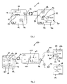
- a first embodiment of the invention provides a short reach passive optical network (PON) system 10 comprising an optical line terminal (OLT) 12, an optical network unit (ONU) 26 and an optical link 40, in the form of 25km single mode fibre, coupled between the OLT 12 and the ONU 26 and configured to transmit downstream and upstream data signals between them.
- the OLT 12 comprises a downlink optical transmitter 14 configured to generate an inverse-return-to-zero (IRZ) line coded downstream data signal, and an uplink optical receiver 16 configured to receive an upstream data signal.
- IRZ inverse-return-to-zero
- IRZ line coding comprises a two-level signal which comprises a light pulse (a continuous wave (CW) pulse) to represent a logical 0 and no pulse, e.g. no light, or at least substantially less light than the CW light level, (also known as a "dark pulse”) to represent a logical 1.
- the signal returns to zero (i.e. CW light) between pulses.
- the dark pulses have a 50% duty cycle, i.e. have a duration of one-half of a clock cycle.
- the dark pulses have a leading edge, being the transition from CW light to no light, and a trailing edge (the pulse "tail”), being the transition from no light to CW light, as shown in Figure 2(a) in relation to the second embodiment.
- the trailing edge being a transition portion, will thus comprise some light.
- the downlink optical transmitter 14 comprises an optical carrier signal source, in the form of a laser 18, operable to generate an optical carrier signal, an IRZ electronic data signal source 22 and an intensity modulator, which here takes the form of a Mach-Zehnder modulator 20.
- the IRZ data signal source 22 generates a 50% duty cycle IRZ data signal (50% IRZ) at 1.25 Gb/s.
- the 50% IRZ data signal drives the Mach-Zehnder modulator 20 to apply the IRZ data signal to the optical carrier signal, to generate a 1.25Gb/s 50% IRZ line coded downstream data signal.
- the downstream data signal is coupled into the optical link 40 via an optical circulator (OC) 24.
- Upstream data signals are coupled from the optical link 40 to the uplink optical received 16 via the optical circulator 24.
- the ONU 26 comprises a downlink optical receiver 28 configured to receive a first portion of a downstream data signal, and an uplink optical remodulator 30 configured to receive a second portion of the downstream data signal and to both remodulate and amplify it to generate a return-to-zero (RZ) line coded upstream data signal.
- RZ return-to-zero
- the ONU 26 further comprises a 3dB coupler 38 coupled on one side to the optical link 40 and on its other side to the downlink optical receiver 28 and to the remodulator 30.
- the 3db coupler 38 acts to split a received downstream data signal into two substantially equal power signals (a signal to be received by the downlink optical receiver 28 and an optical seed signal for the remodulator 30), and couples the signals to the downlink optical receiver 28 and the remodulator 30 respectively.
- the ONU 26 further comprises a local clock signal source associated with the downstream receiver 28.
- the uplink optical remodulator 30 comprises an electro-optic modulator in the form of a reflective semiconductor optical amplifier (R-SOA) 32, an RZ electronic data signal source 34 and signal synchronisation apparatus in the form of a variable optical delay line (ODL) 36.
- R-SOA reflective semiconductor optical amplifier
- ODL variable optical delay line
- the R-SOA 32 in this example comprises a commercially available device providing 21 dB of small signal gain at 50mA bias current, 2 dBm output saturation power, 1 dB polarization dependent gain and 8 db noise figure, and is biased at 70mA.
- the R-SOA 32 is operated outside of its saturation regime.
- the seed signal has a power of between -15dBm and -35dBm.
- the RZ data signal source generates a 7V peak-to-peak 1.25Gb/s RZ data signal.
- the optical delay line 36 acts to synchronize the upstream data signal (i.e. the RZ data signal) with the downstream data signal, in conjunction with the local clock source, so that the upstream data signal is interleaved by one-half bit with respect to the incoming downstream data signal.
- the RZ data signal is applied (i.e. the R-SOA remodulates and amplifies) only when the seed signal comprises a CW signal, as follows.
- the seed signal comprises the dark pulse tail, which is suppressed by the R-SOA 32 to form a logical 0 for the upstream data signal or is amplified by the R-SOA 32 to form a logical 1.
- the downstream data signal comprises a light pulse (a logical 0)
- the seed signal comprises a CW light pulse having a duration equal to the full clock cycle, one-half of the light pulse is suppressed by the R-SOA 32 to form a logical 1 or the whole pulse is suppressed by the R-SOA 32 to form a logical 0.
- optical link fibre 40 may be of a different length, and may in particular be a long reach fibre having a length of, for example, 80-100km, to form a long reach passive optical network system.
- a second embodiment of the invention provides a wavelength division multiplexed (WDM) passive optical network (PON) system 50 which is an extension of the passive optical network system 10 of the first embodiment.
- WDM wavelength division multiplexed
- PON passive optical network
- the OLT 52 comprises a downlink optical transmitter (Tx) array 54 configured to generate plurality of inverse-return-to-zero (IRZ) line coded downstream data signals, each at a different one of a plurality of optical carrier wavelengths, and an uplink optical receiver (Rx) array 60 configured to receive a plurality of upstream data signals at said carrier wavelengths.
- Tx downlink optical transmitter
- Rx uplink optical receiver
- the downlink Tx array 54 comprises a plurality of optical carrier signal sources in the form of lasers 56.
- the resulting plurality of IRZ line coded downstream data signals are multiplexed through an arrayed waveguide grating (AWG) 58 and coupled via the optical circulator (OC) 24 into a single mode feeder fibre 66, having a length of 20km, which forms the first part of the optical link.
- AWG arrayed waveguide grating
- OC optical circulator
- the uplink Rx array 60 comprises a corresponding plurality of photodiodes 62. Upstream data signals are coupled to the photodiodes 62 from the feeder fibre 66 through the circulator 24 and a demultiplexed in a second AWG 64.
- the WDM-PON 50 comprises a plurality of ONUs 26 (only two are shown for clarity).
- the optical link in this embodiment comprises the single mode feeder fibre 66, a plurality of distribution fibres 70 (only two, ⁇ L , ⁇ S , are shown for clarity) and a third AWG 68 coupled between the feeder fibre 66 and the distribution fibres 70.
- the distribution fibres are long reach distribution fibres each having a length of 60km.
- the third AWG 68 acts to demultiplex the plurality of downstream data signals and route each to their respective distribution fibre 70 and ONU 26, and acts to multiplex a plurality of upstream data signals received from the ONUs 26 into the feeder fibre 66 for transmission upstream to the OLT 52.
- the downlink optical receivers comprise a photodiode 28a and a digital receiver 28b.
- a third embodiment of the invention provides a hybrid WDM/Time Division Multiple Access (TDMA) PON 80, which is substantially the same as the WDM-PON 50 of the second embodiment, with the following modifications.
- TDMA Time Division Multiple Access
- one or more of the carrier signal wavelengths is used for a short reach TDMA sub-network 81 from the third AWG 68 (only 1, ⁇ S , is shown for clarity).
- the TDMA sub-network 81 comprises a short reach distribution fibre 82, a 1xN (in this example 1x6) optical power splitter 84 and six ONUs 26.
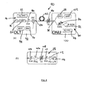
- Figure 4(a) shows a schematic representation of an experimental set-up of a passive optical network 90 according to the second embodiment of the invention.
- the same reference numbers are retained for corresponding features.
- the experimental set-up is tested using a single wavelength channel. It will be appreciated that the same results would be achieved for each of a plurality of wavelength channels in the WDM-PON 50 of Figure 2 .
- the downstream IRZ data signal was obtained by modulating an external cavity laser 18 operating at 1542 nm with a Mach-Zender Intensity modulator 20; it was driven by an electrical pseudo-random bit sequence (PRBS), 2 ⁇ 7-1 bits long encoded in an IRZ pattern at 1.25 Gb/s generated by a pulse pattern generator 22. This length of data is compatible with 8B10B coding.
- PRBS pseudo-random bit sequence
- the downstream transmitter 14 further comprised a Variable Optical Attenuator (VOA) 94, used to set the optical power level received at the ONU 100.
- VOA Variable Optical Attenuator
- the VOA 94 was placed at the transmitter 14 in order to evaluate the impairments due to back-reflections (Rayleigh and Fresnel scattering) on both the downstream and upstream channels.
- the AWG 68 of Figure 2 was emulated by means of a 0.8 nm tunable optical filter (TF) 96, having 3 dB insertion loss. Although the experiment was conducted on a single wavelength, this filter was needed to reject amplified spontaneous emission (ASE) noise generated by the R-SOA when operated out of the saturation regime.
- TF 0.8 nm tunable optical filter
- the ONU 100 comprised a 3 dB coupler 38, a receiver (Rx) 28 and an R-SOA 32.
- the R-SOA 32 was a commercially available device, providing 21 dB of small signal gain at 50mA bias current, 2 dBm output saturation power, 1 dB polarization dependent gain and 8 db noise figure.
- the R-SOA 32 was biased at 70mA and driven with a 7V peak-to-peak RZ encoded signal (a 2 ⁇ 7-1 long PRBS, at 1.25 Gb/s, as for the downstream data signal).
- An optical Delay Line (ODL) 36 was used to ensure proper synchronization between downstream and upstream data signals.
- the ONU receiver 28 comprises a PIN diode detector 112, which was optically pre-amplified in order to overcome the low responsivity of the available PIN diode detector 112 and allow Bit Error ratio (BER) measurement with low received power levels.
- the optical preamplification was performed by a double stage Erbium Doped Fiber Amplifier (EDFA) (PRE) 106 providing 45 dB gain with a 5 dB noise figure. It was followed by a tunable optical filter (TF) 108 having 0.2 nm full-width half-maximum (FWHM) linewidth for ASE noise removal.
- the EDFA preamplifier 106 was fed with an out-of-band CW optical signal in order to keep it properly working.
- a post-detection 4th-order Bessel low-pass filter (LPF) having a 1.87 GHz bandwidth was used to reject high frequency noise from the received signal.
- LPF Bessel low-pass filter
- a narrower post-detection filter would be preferred, but was not available.
- BER measurements were conducted by keeping a constant optical power to the photodiode (-6 dBm).
- the receiver 28 enabled BER measurement to be made with single channel input optical power as low as -50 dBm.
- the same receiver was used as the uplink receiver 16 at the OLT 92 to characterize the upstream signal transmission performance.
- an avalanche photodiode (APD) would be preferred as the receiver, at least at the ONU side of the PON 90.
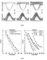
- FIG. 5 shows the eye diagrams of the downstream (DS) signal and the upstream (US) signal.
- the downstream eye-diagrams are shown back-to-back (a) and after transmission (b, c).
- the eye diagram of the downstream signal is only slightly affected by propagation across the PON 90.
- the upstream signal is applied (RSOA 32 turned on)
- the DS eye diagram shows an incremented noise on the "space" (dark pulse) level. This is due to Rayleigh backscattering generated by the upstream signal. The slight power penalty induced by this effect is detailed further below.
- the US eye diagrams shown were recorded at the RSOA output, and refer to three seed signal power levels: -25 dBm (d), -30 dBm (e) and - 35 dBm (f).
- the upstream eye diagrams are affected by a patterning effect, due to the remodulation process; the remodulated, upstream pulses have slightly different shapes depending on whether the R-SOA 32 is remodulating the seed signal to a 0 or a 1. As it can be seen, this patterning is not dependent on the power of the seed signal. Although this patterning causes some power penalty, the observed eye-diagrams are still wide open and clear for all of the seed signal powers considered.
- the BER measurements for the long reach, 80 km SMF feeder fibre 40 are shown in Figure 6 .
- the downstream signal acquires about 1.5 dB of power penalty after the 80 km SMF transmission. This power penalty is due in part to Rayleigh scattering generated inside the feeder fibre 40 by the upstream signal; when the R-SOA 32 is disconnected, the downlink power penalty is reduced by about 0.5 dB. This additional power penalty is observed only when the R-SOA 32 is highly saturated (i.e. when it is fed with optical power exceeding -15 dBm) thus providing around 0 dBm of remodulated power. In operating regimes in which the R-SOA 32 is operated far from saturation, the upstream remodulated power does not affect the downstream sensitivity.
- the upstream BER performance is shown in Figure 7 .
- the transmission power penalty of the upstream signal is essentially determined by the power of the seed signal delivered to the R-SOA 32.
- Three seed power levels at which the R-SOA 32 operated outside its saturation regime were investigated: -25, -30, and -35 dBm.
- the upstream transmission power penalty is 4.5dB and 5.5 dB for -25 and -30 dBm seed signal power levels respectively.
- the power penalty for these two seed signal power levels is mostly due to Rayleigh back scattering, which limits the Optical Signal to Noise Ratio (OSNR) of the upstream signal at the OLT to 15 dB.
- OSNR Optical Signal to Noise Ratio
- the performance of the PON 90 was also tested for a short reach environment, having a 26 km SMF feeder fibre 40, meaning that hybrid WDM/TDMA can be exploited.
- the extra power budget available at the R-SOA 32 may be used to increase the power splitting ratio of the coupler at the ONU, thus increasing the number of ONUs that can share the same wavelength.
- the downstream channel performance is practically unchanged: however, we note the same 0.5 dB power penalty due to Rayleigh back-reflection generated by the upstream channel.
- the upstream channel also shows comparable performance to the long reach test example. Due to the short reach feeder fibre 40 having a lower insertion loss of around 6dB, it is possible to seed the R-SOA 32 with seed signals having higher power levels, of up to -15dBm. By operating the R-SOA 32 at its maximum gain, it is possible to obtain a higher signal to reflected power ratio for the upstream channel (measured to the OLT 92) as compared to the long reach example. In particular, the upstream OSNR was higher than 20dB, which is a 10dB improvement compared to the long reach example. The highest power penalty was observed for seed signal power levels lower than -30dB (similarly to the long reach example), when the OSNR degradation due to the R-SOA 32 becomes significant.
- the OLT 92 It is common in passive optical networks for the OLT 92 to be able to transmit optical signals having power levels of 1mW per channel (0 dBm/ch) and to have total link losses in the order of 12dB per channel (4dB at each AWG, plus 6dB for the feeder fibre 40).
- the PON 90 at OdBm/ch, it is possible to have 18dB of loss in transmission across the PON 90 and be able to feed each ONU 26 with a seed signal having the minimum acceptable optical power level. This corresponds to a 1x64 power splitter, i.e. 64 ONUs 26 may be provided on a single PON 90.
- a 3dB coupler is used at the ONU input.
- the downstream receiver 28 would be replaced by an avalanche photodiode (APD) which has a sensitivity of around -40dBm at the bit-rate used.
- APD avalanche photodiode
- a fourth embodiment of the invention provides a passive optical network line coding method 100 which comprises generating an IRZ line coded downstream (DS) data signal 102, and receiving a portion of the DS signal 106 and remodulating it (114, 116, 118, 120, 122, 124) to generate a RZ line coded upstream (US) data signal.
- the method is suitable for use with any of the above described embodiments, and is described in relation to the PON architectures of the described embodiments.
- an IRZ line coded DS signal is generated 102, at the OLT of a passive optical network (PON) and is transmitted 104 across PON network link to an ONU.
- PON passive optical network
- the downstream signal is power split and one part is sent to the downlink receiver of the ONU, with the other part being sent, as a seed signal, to the upstream transmitter, which comprises an electro-optic modulator in the form of an R-SOA, of the ONU.
- the R-SOA is operated outside of its saturation regime.
- a delay is applied 108 to the seed signal, using an optical delay line, in order to synchronize the US and DS signals and interleave 108 the US signal by one-half bit with respect to the DS signal. Synchronization is also assisted by reference to a local clock signal provided at the ONU, associated with the downlink receiver.
- the seed signal is received at the R-SOA 110 and, for each bit in the downstream data signal, the bit is identified as a dark pulse or a light (CW) pulse 112. If the received bit is a dark pulse 114, the pulse is remodulated to form an upstream data bit as follows: the dark pulse tail is amplified 116 in order to generate a logical 1 for the upstream data signal or is suppressed 118 in order to generate a logical 0 for the upstream data signal.
- the pulse is remodulated to form an upstream data bit as follows: one half of the light pulse is suppressed122 to generate a logical 1 for the upstream data signal, or the whole pulse is suppressed 124 to generate a logical 0 for the upstream data signal.
- the remodulated US signal bit is then transmitted back across the network link to the OLT.
- the described embodiments provide various advantages, as follows.
- the described passive optical network systems and method relax the constraints due to power losses in WDM PONs based on colourless reflective ONUs, such as those described comprising R-SOAs.
- Using the described systems and method it is possible to extend the range of operation of R-SOAs.
- the described systems provide long reach PON systems which do not require any in-line amplification.
- the described systems can be used to implement short reach PONs based on a hybrid WDM/TDMA approach, serving up to 64 ONUs, which doubles the capacity of the G-PON standard.
- the described PON systems enable both long reach and short reach/TDMA to be implemented for different wavelengths, opening the possibility to the realization of more flexible passive optical networks.
- the described PONs offer error-free full downstream re-modulation by seeding the R-SOA with power levels as low as -35 dBm.
- the described systems and method dramatically increase the WDM-PON power budget, thus allowing implementation of, for example, hybrid WDM/TDMA short reach PONs. If operated at 1.25 Gb/s this coding technique is quite tolerant to chromatic dispersion impairments. It thus allows implementation of long reach PONs without requiring in-line amplifiers, hence maintaining a totally passive PON.
- the described systems enable bidirectional transmission over 80 km feeder fiber without any other source of optical amplification.
- the use of IRZ/RZ coding is completely transparent to the WDM-PON architecture: it can be implemented to allow for longer reaches or TDMA on selected wavelengths, thus providing an high degree of flexibility in design and deployment of next generation WDM-PONs.
- the R-SOA used at the ONU as the remodualator is operated outside the saturation regime. This allows the power budget constraints on the PON to be relaxed. Another important advantage is that there is no lower limitation on the extinction ratio of the downstream signal, because the portion of the downstream signal that forms the seed signal for the R-SOA is always remodulated at times where there is CW light. Another advantage of the described systems is that the same architecture as standard WDM-PONs may be used; the optical "front-end" of the ONU (receiver and R-SOA) is identical to the one used in WDM-PON based on NRZ remodulation. Thus it is possible to use the described method and implement the described systems to upgrade the reach of already installed WDM-PONs.
Landscapes
- Engineering & Computer Science (AREA)
- Computer Networks & Wireless Communication (AREA)
- Signal Processing (AREA)
- Physics & Mathematics (AREA)
- Electromagnetism (AREA)
- Optical Communication System (AREA)
- Eye Examination Apparatus (AREA)
Claims (26)
- Passives optisches Netzsystem (10, 50, 80, 90), umfassend:ein optisches Leitungsendgerät (12, 52, 92), umfassend: einen optischen Abwärtssender (14, 54), der so konfiguriert ist, dass er ein Inverse-Rückkehr-nach-Null-leitungscodiertes Abwärtsdatensignal erzeugt; und einen optischen Aufwärtsempfänger (16, 60), der so konfiguriert ist, dass er ein Aufwärtsdatensignal empfängt;eine optische Netzeinheit (26, 100), umfassend: einen optischen Abwärtsempfänger (28), der so konfiguriert ist, dass er einen ersten Abschnitt des Abwärtsdatensignals empfängt; und einen optischen Aufwärtsremodulator (30), der so konfiguriert ist, dass er einen zweiten Abschnitt des Abwärtsdatensignals empfängt und es remoduliert, um ein Rückkehr-nach-Null-leitungscodiertes Aufwärtsdatensignal zu erzeugen; undeine optische Strecke (40, 66, 70, 82), die zwischen das optische Leitungsendgerät und die optische Netzeinheit gekoppelt und so konfiguriert ist, dass sie Abwärts- und Aufwärtsdatensignale dazwischen überträgt.
- Passives optisches Netzsystem nach Anspruch 1, wobei das Inverse-Rückkehr-nach-Null-leitungscodierte Abwärtsdatensignal dunkle Impulse mit einem Tastverhältnis von ungefähr fünfzig Prozent umfasst.
- Passives optisches Netzsystem nach Anspruch 1 oder 2, wobei der optische Aufwärtsremodulator (30) einen elektrooptischen Modulator (32) umfasst, der so konfiguriert ist, dass er durch ein Rückkehr-nach-Null-codiertes, elektronisches Datensignal (34) angesteuert wird.
- Passives optisches Netzsystem nach einem der vorhergehenden Ansprüche, wobei der optische Aufwärtsremodulator (30) so konfiguriert ist, dass er den zweiten Abschnitt des Abwärtsdatensignals sowohl remoduliert als auch verstärkt, um ein Rückkehr-nach-Null-leitungscodiertes Aufwärtsdatensignal zu erzeugen.
- Passives optisches Netzsystem nach Anspruch 4, wobei der optische Aufwärtsremodulator (30) einen reflektiven optischen Halbleiterverstärker (32) umfasst, der so konfiguriert ist, dass er durch ein Rückkehr-nach-Null-codiertes, elektronisches Datensignal (34) angesteuert wird.
- Passives optisches Netzsystem nach Anspruch 5, wobei der reflektive optische Halbleiterverstärker (32) bei Empfang eines dunklen Impulses (72) mit einer vorderen Impulsflanke (72a) und einer hinteren Impulsflanke (72b) so betrieben werden kann, dass er die hintere Flanke des dunklen Impulses unterdrückt, um eine logische Null für das Aufwärtsdatensignal zu bilden, oder die hintere Flanke des dunklen Impulses verstärkt, um eine logische Eins zu bilden, und bei Empfang eines hellen Impulses so betrieben werden kann, dass er eine Hälfte des Impulses unterdrückt, um eine logische Eins zu bilden, oder den ganzen Impuls unterdrückt, um eine logische Null zu bilden.
- Passives optisches Netzsystem nach Anspruch 5 oder 6, wobei der reflektive optische Halbleiterverstärker (32) so konfiguriert ist, dass er außerhalb seines Sättigungsbetriebszustands für Eingangsleistungen auf dem Lichtleistungspegel des zweiten Abschnitts des Abwärtsdatensignals arbeitet.
- Passives optisches Netzsystem nach einem der vorhergehenden Ansprüche, wobei die optische Netzeinheit (26, 100) ferner eine Signalsynchronisationsvorrichtung (36) umfasst, die so konfiguriert ist, dass sie das Rückkehr-nach-Null-leitungscodierte Aufwärtsdatensignal in Bezug auf das eingehende Inverse-Rückkehr-nach-Null-leitungscodierte Abwärtsdatensignal um ein halbes Bit überlappt.
- Passives optisches Netzsystem nach Anspruch 8, wobei die Signalsynchronisationsvorrichtung eine optische Verzögerungsleitung (36) umfasst, die zwischen der optischen Strecke (40, 70, 82) und dem optischen Aufwärtsremodulator (30) vorgesehen ist.
- Passives optisches Netzsystem (50, 80) nach einem der vorhergehenden Ansprüche, wobei das passive optische Netzsystem eine Mehrzahl von optischen Netzeinheiten (26) umfasst, und die optische Strecke (66, 70, 82) zwischen das optische Leitungsendgerät (60) und jede der optischen Netzeinheiten gekoppelt ist.
- Optische Netzeinheit (26, 100), umfassend:einen optischen Abwärtsempfänger (28), der so konfiguriert ist, dass er einen ersten Abschnitt eines Inverse-Rückkehr-nach-Null-leitungscodierten Abwärtsdatensignals empfängt; undeinen optischen Aufwärtsremodulator (30), der so konfiguriert ist, dass er einen zweiten Abschnitt des Abwärtsdatensignals empfängt und es remoduliert, um ein Rückkehr-nach-Null-leitungscodiertes Aufwärtsdatensignal zu erzeugen.
- Optische Netzeinheit nach Anspruch 11, wobei der optische Aufwärtsremodulator (30) einen elektrooptischen Modulator (32) umfasst, der so konfiguriert ist, dass er durch ein Rückkehr-nach-Null-codiertes, elektronisches Datensignal (34) angesteuert wird.
- Optische Netzeinheit nach Anspruch 11 oder 12, wobei der optische Aufwärtsremodulator (30) so konfiguriert ist, dass er den zweiten Abschnitt des Abwärtsdatensignals sowohl remoduliert als auch verstärkt, um ein Rückkehr-nach-Null-leitungscodiertes Aufwärtsdatensignal zu erzeugen.
- Optische Netzeinheit nach Anspruch 13, wobei der optische Aufwärtsremodulator (30) einen reflektiven optischen Halbleiterverstärker (32) umfasst, der so konfiguriert ist, dass er durch ein Rückkehr-nach-Null-codiertes, elektronisches Datensignal (34) angesteuert wird.
- Optische Netzeinheit nach Anspruch 14, wobei der reflektive optische Halbleiterverstärker (32) bei Empfang eines dunklen Impulses (72) mit einer vorderen Impulsflanke (72a) und einer hinteren Impulsflanke (72b) so betrieben werden kann, dass er die hintere Flanke des dunklen Impulses unterdrückt, um eine logische Null für das Aufwärtsdatensignal zu bilden, oder die hintere Flanke des dunklen Impulses verstärkt, um eine logische Eins zu bilden, und bei Empfang eines hellen Impulses so betrieben werden kann, dass er eine Hälfte des Impulses unterdrückt, um eine logische Eins zu bilden, oder den ganzen Impuls unterdrückt, um eine logische Null zu bilden.
- Optische Netzeinheit nach Anspruch 14 oder 15, wobei der reflektive optische Halbleiterverstärker (32) so konfiguriert ist, dass er außerhalb seines Sättigungsbetriebszustands für Eingangsleistungen auf dem Lichtleistungspegel des zweiten Abschnitts des Abwärtsdatensignals arbeitet.
- Optische Netzeinheit nach einem der Ansprüche 11 bis 16, wobei die optische Netzeinheit (26) ferner eine Signalsynchronisationsvorrichtung (36) umfasst, die so konfiguriert ist, dass sie das Rückkehr-nach-Null-leitungscodierte Aufwärtsdatensignal in Bezug auf das eingehende Inverse-Rückkehr-nach-Null-leitungscodierte Abwärtsdatensignal um ein halbes Bit überlappt.
- Optische Netzeinheit nach Anspruch 17, wobei die Signalsynchronisationsvorrichtung eine optische Verzögerungsleitung (36) umfasst, die zwischen der optischen Strecke (40) und dem optischen Aufwärtsremodulator (30) vorgesehen ist.
- Leitungscodierungsverfahren (100) für ein passives optisches Netz, umfassend:Erzeugen eines Inverse-Rückkehr-nach-Null-leitungscodierten Abwärtsdatensignals (102); undEmpfangen eines Abschnitts des Abwärtsdatensignals (110) und Remodulieren desselben (114, 116, 118, 120, 122, 124), um ein Rückkehr-nach-Null-leitungscodiertes Aufwärtsdatensignal zu erzeugen.
- Leitungscodierungsverfahren für ein passives optisches Netz nach Anspruch 19, wobei das Inverse-Rückkehr-nach-Null-leitungscodierte Abwärtsdatensignal dunkle Impulse mit einem Tastverhältnis von ungefähr fünfzig Prozent umfasst.
- Leitungscodierungsverfahren für ein passives optisches Netz nach Anspruch 19 oder 20, wobei die Remodulation (114, 116, 118, 120, 122, 124) des Abschnitts des Abwärtsdatensignals durch Liefern des Abschnitts des Abwärtsdatensignals an einen elektrooptischen Modulator (32) und Ansteuern des elektrooptischen Modulators mit einem Rückkehr-nach-Null-codierten, elektronischen Datensignal (34) erfolgt.
- Leitungscodierungsverfahren für ein passives optisches Netz nach einem der Ansprüche 19 bis 21, wobei das Leitungscodierungsverfahren ein Remodulieren und Verstärken (114, 116, 118, 120, 122, 124) des Abschnitts des Abwärtsdatensignals umfasst, um ein Rückkehr-nach-Null-leitungscodiertes Aufwärtsdatensignal zu erzeugen.
- Leitungscodierungsverfahren für ein passives optisches Netz nach Anspruch 22, wobei die Remodulation und Verstärkung des Abschnitts des Abwärtsdatensignals durch Liefern des Abschnitts des Abwärtsdatensignals an einen reflektiven optischen Halbleiterverstärker (110) und Ansteuern des reflektiven optischen Halbleiterverstärkers mit einem Rückkehr-nach-Null-codierten, elektronischen Datensignal (114, 116, 118, 120, 122, 124) erfolgt.
- Leitungscodierungsverfahren für ein passives optisches Netz nach einem der Ansprüche 19 bis 23, wobei das remodulierte Aufwärtsdatensignal (126) dadurch erzeugt wird, dass bei Empfang eines dunklen Impulses (72, 112, 114) mit einer vorderen Impulsflanke (72a) und einer hinteren Impulsflanke (72b) die hintere Flanke des dunklen Impulses unterdrückt wird, um eine logische Null für das Aufwärtsdatensignal zu bilden (118), oder verstärkt wird (116), um eine logische Eins zu bilden, und bei Empfang eines hellen Impulses (112, 120) eine Hälfte des Impulses unterdrückt wird, um eine logische Eins zu bilden (122), oder der ganze Impuls unterdrückt wird, um eine logische Null zu bilden (124).
- Leitungscodierungsverfahren für ein passives optisches Netz nach einem der Ansprüche 19 bis 24, wobei das Leitungscodierungsverfahren ein Überlappen des Rückkehr-nach-Null-leitungscodierte Aufwärtsdatensignals in Bezug auf das eingehende Inverse-Rückkehr-nach-Null-leitungscodierte Abwärtsdatensignal um ein halbes Bit umfasst.
- Leitungscodierungsverfahren für ein passives optisches Netz nach Anspruch 25, wobei die Synchronisation der Abwärts- und Aufwärtsdatensignale zum Überlappen durch Einführen einer optischen Verzögerung in den Abschnitt des zu remodulierenden Abwärtsdatensignals erfolgt (108).
Applications Claiming Priority (1)
| Application Number | Priority Date | Filing Date | Title |
|---|---|---|---|
| PCT/EP2008/061671 WO2010025767A1 (en) | 2008-09-04 | 2008-09-04 | Passive optical networks |
Publications (2)
| Publication Number | Publication Date |
|---|---|
| EP2332276A1 EP2332276A1 (de) | 2011-06-15 |
| EP2332276B1 true EP2332276B1 (de) | 2012-01-25 |
Family
ID=40599624
Family Applications (1)
| Application Number | Title | Priority Date | Filing Date |
|---|---|---|---|
| EP08803641A Not-in-force EP2332276B1 (de) | 2008-09-04 | 2008-09-04 | Passive optische netzwerke |
Country Status (9)
| Country | Link |
|---|---|
| US (1) | US20110236021A1 (de) |
| EP (1) | EP2332276B1 (de) |
| CN (1) | CN102204137B (de) |
| AT (1) | ATE543279T1 (de) |
| AU (1) | AU2008361451B2 (de) |
| DK (1) | DK2332276T3 (de) |
| ES (1) | ES2381451T3 (de) |
| PT (1) | PT2332276E (de) |
| WO (1) | WO2010025767A1 (de) |
Families Citing this family (26)
| Publication number | Priority date | Publication date | Assignee | Title |
|---|---|---|---|---|
| US8909050B2 (en) * | 2010-04-30 | 2014-12-09 | Telefonaktiebolaget L M Ericsson (Publ) | Passive optical networks |
| WO2012087194A1 (en) | 2010-12-20 | 2012-06-28 | Telefonaktiebolaget L M Ericsson (Publ) | Method and arrangement for receiving an optical input signal and transmittning an optical output signal |
| US8687971B2 (en) * | 2011-01-31 | 2014-04-01 | Telefonaktiebolaget Lm Ericsson (Publ) | System, laser-on-CMOS chip, and method for setting a wavelength to be used by the laser-on-CMOS chip |
| WO2013007277A1 (en) * | 2011-07-08 | 2013-01-17 | Telefonaktiebolaget L M Ericsson (Publ) | Optical access network |
| WO2013007318A1 (en) | 2011-07-11 | 2013-01-17 | Telefonaktiebolaget L M Ericsson (Publ) | Apparatus and method for a passive optical network |
| US9088838B2 (en) * | 2011-07-18 | 2015-07-21 | Telefonaktiebolaget L M Ericsson (Publ) | OTM functionality in SOA based transceivers |
| JP5808859B2 (ja) * | 2011-07-29 | 2015-11-10 | テレフオンアクチーボラゲット エル エム エリクソン(パブル) | 光アクセスネットワーク |
| US8817589B2 (en) | 2011-09-16 | 2014-08-26 | Telefonaktiebolaget L M Ericsson (Publ) | Communications network apparatus and line coding method |
| US9184842B2 (en) | 2011-10-06 | 2015-11-10 | Telefonaktiebolaget L M Ericsson (Publ) | Apparatus for communicating a plurality of antenna signals at different optical wavelengths |
| US8923672B2 (en) | 2011-11-10 | 2014-12-30 | Alcatel Lucent | Wavelength router for a passive optical network |
| US9252912B2 (en) | 2012-04-09 | 2016-02-02 | Telefonaktiebolaget L M Ericsson (Publ) | Method for routing and spectrum assignment |
| US9002194B2 (en) | 2012-04-09 | 2015-04-07 | Telefonaktiebolaget L M Ericsson (Publ) | Optical-layer multipath protection for optical network |
| US8929738B2 (en) | 2012-05-30 | 2015-01-06 | Telefonaktiebolaget L M Ericsson (Publ) | Resilience in an access subnetwork ring |
| US9112635B2 (en) | 2012-06-13 | 2015-08-18 | Telefonaktiebolaget L M Ericsson (Publ) | Methods and apparatus for a passive access subnetwork |
| CN102946282B (zh) * | 2012-12-07 | 2016-01-13 | 烽火通信科技股份有限公司 | 光传输系统、光收发单元及其相干频率调整方法 |
| CN103327422B (zh) * | 2013-05-27 | 2015-11-25 | 浙江工业大学 | 一种用于视频监控的低成本无源光网络 |
| EP2830239B1 (de) * | 2013-07-23 | 2018-09-12 | ADVA Optical Networking SE | Verfahren, System und Sender-Empfängervorrichtung zum bidirektionalen Übertragen digitaler optischer Signale über einen optischen Übertragungslink |
| CN104469562B (zh) * | 2013-09-18 | 2018-12-04 | 上海诺基亚贝尔股份有限公司 | 支持onu间交互的onu和远程节点 |
| WO2015183364A2 (en) * | 2014-05-09 | 2015-12-03 | Sikorsky Aircraft Corporation | Method and apparatus for condition based maintenance of fiber networks on vehicles |
| US10135218B2 (en) * | 2015-10-02 | 2018-11-20 | Ayar Labs, Inc. | Multi-wavelength laser system for optical data communication links and associated methods |
| US10200121B2 (en) * | 2017-06-14 | 2019-02-05 | At&T Intellectual Property I, L.P. | Reachability determination in wavelength division multiplexing network based upon fiber loss measurements |
| CN108234056B (zh) * | 2018-01-17 | 2019-12-24 | 四川泰富地面北斗科技股份有限公司 | 采用同波长半双工方式的单纤双向时间传递方法与系统 |
| CN114070389B (zh) * | 2020-07-31 | 2025-04-29 | 中兴通讯股份有限公司 | 用于光模块的apd性能检测方法、装置、光网络及介质 |
| CN214101388U (zh) * | 2020-08-20 | 2021-08-31 | 华为技术有限公司 | 一种分光设备和分光系统 |
| EP4331177A4 (de) | 2021-04-28 | 2025-03-12 | Anametric, Inc. | Systeme und verfahren für hybride physikalische unklonbare funktionen |
| AU2023319999A1 (en) | 2022-08-05 | 2025-02-20 | Anametric, Inc. | Systems and methods for implementing structures for physical unclonable functions |
Family Cites Families (5)
| Publication number | Priority date | Publication date | Assignee | Title |
|---|---|---|---|---|
| USH2075H1 (en) * | 1998-10-13 | 2003-08-05 | At&T Corp. | Restorable architectures for fiber-based broadband local access networks |
| WO2004112264A2 (en) * | 2003-06-10 | 2004-12-23 | Ubi Systems, Inc. | System and method for performing high-speed communications over fiber optical networks |
| KR100842248B1 (ko) * | 2006-03-21 | 2008-06-30 | 한국전자통신연구원 | 맨체스터 코드화 신호의 재변조 방식을 갖는 광 통신시스템 및 방법 |
| CN1980098B (zh) * | 2006-11-01 | 2010-08-18 | 华为技术有限公司 | 一种波分复用光接入系统及其数据收发方法 |
| KR100870897B1 (ko) * | 2007-02-06 | 2008-11-28 | 한국과학기술원 | 전송품질이 개선된 반사형 반도체 광증폭기 기반광가입자망 시스템 |
-
2008
- 2008-09-04 DK DK08803641.3T patent/DK2332276T3/da active
- 2008-09-04 AU AU2008361451A patent/AU2008361451B2/en not_active Ceased
- 2008-09-04 CN CN200880131920.XA patent/CN102204137B/zh not_active Expired - Fee Related
- 2008-09-04 US US13/061,501 patent/US20110236021A1/en not_active Abandoned
- 2008-09-04 WO PCT/EP2008/061671 patent/WO2010025767A1/en not_active Ceased
- 2008-09-04 ES ES08803641T patent/ES2381451T3/es active Active
- 2008-09-04 AT AT08803641T patent/ATE543279T1/de active
- 2008-09-04 EP EP08803641A patent/EP2332276B1/de not_active Not-in-force
- 2008-09-04 PT PT08803641T patent/PT2332276E/pt unknown
Also Published As
| Publication number | Publication date |
|---|---|
| CN102204137A (zh) | 2011-09-28 |
| US20110236021A1 (en) | 2011-09-29 |
| AU2008361451A1 (en) | 2010-03-11 |
| CN102204137B (zh) | 2015-07-29 |
| WO2010025767A1 (en) | 2010-03-11 |
| ATE543279T1 (de) | 2012-02-15 |
| PT2332276E (pt) | 2012-03-28 |
| DK2332276T3 (da) | 2012-02-27 |
| AU2008361451B2 (en) | 2013-07-11 |
| ES2381451T3 (es) | 2012-05-28 |
| EP2332276A1 (de) | 2011-06-15 |
Similar Documents
| Publication | Publication Date | Title |
|---|---|---|
| AU2008361451B2 (en) | Passive optical networks | |
| KR100921797B1 (ko) | 파장분할 다중화 방식의 수동형 광가입자망 시스템 | |
| KR100870897B1 (ko) | 전송품질이 개선된 반사형 반도체 광증폭기 기반광가입자망 시스템 | |
| Akanbi et al. | A new scheme for bidirectional WDM-PON using upstream and downstream channels generated by optical carrier suppression and separation technique | |
| CN113169799B (zh) | 具有增强灵活性的光线路终端和光纤接入系统 | |
| US8478125B2 (en) | Optical PON network using passive DPSK demodulation | |
| Sundar et al. | Performance investigation of 16/32-channel DWDM PON and long-reach PON systems using an ASE noise source | |
| Martínez et al. | Novel WDM-PON architecture based on a spectrally efficient IM-FSK scheme using DMLs and RSOAs | |
| Calabretta et al. | A bidirectional WDM/TDM-PON using DPSK downstream signals and a narrowband AWG | |
| Koponen et al. | A duplex WDM passive optical network with 1: 16 power split using reflective SOA remodulator at ONU | |
| Cho et al. | Broadcast transmission in WDM-PON using a broadband light source | |
| Kottke et al. | Coherent subcarrier-WDM-PON system with SSB modulation and wavelength reuse | |
| Berrettini et al. | Colorless WDM-PON architecture for Rayleigh backscattering and path-loss degradation mitigation | |
| EP2260596B1 (de) | Verbesserungen in bezug auf optische netzwerke | |
| Spolitis et al. | Extended reach 32-channel dense spectrum-sliced optical access system | |
| Berrettini et al. | Colorless WDM-PON performance improvement exploiting a service-ONU for multiwavelength distribution | |
| Raharimanitra et al. | 40 Gb/s NG-PON system using low electrical bandwidth tunable receiver and emitter at 10 Gb/s | |
| Cavaliere et al. | Migration towards high speed optical access enabled by WDM techniques | |
| Berrettini et al. | Testbed for experimental analysis on seamless evolution architectures from GPON to high capacity WDM-PON | |
| HK1159346A (en) | Passive optical networks | |
| Imtiaz et al. | Power budget analysis of dual/single feeder fiber WDMPON | |
| Cheng et al. | A novel hybrid WDM/TDM-PON using downlink DPSK and uplink remodulated OOK signals based on a shared DI | |
| Bauwelinck et al. | Multi-operability and dynamic bandwidth allocation in PONs with electrically reconfigurable SOA/REAM-based ONUs | |
| Aundhekar et al. | Performance improvement of wavelength division multiplexing passive optical networks (WDM PONs) using AWG | |
| Ghanbarisabagh et al. | A Survey on High-Capacity OFDM-based Passive Optical Networks |
Legal Events
| Date | Code | Title | Description |
|---|---|---|---|
| PUAI | Public reference made under article 153(3) epc to a published international application that has entered the european phase |
Free format text: ORIGINAL CODE: 0009012 |
|
| 17P | Request for examination filed |
Effective date: 20110217 |
|
| AK | Designated contracting states |
Kind code of ref document: A1 Designated state(s): AT BE BG CH CY CZ DE DK EE ES FI FR GB GR HR HU IE IS IT LI LT LU LV MC MT NL NO PL PT RO SE SI SK TR |
|
| AX | Request for extension of the european patent |
Extension state: AL BA MK RS |
|
| GRAP | Despatch of communication of intention to grant a patent |
Free format text: ORIGINAL CODE: EPIDOSNIGR1 |
|
| DAX | Request for extension of the european patent (deleted) | ||
| GRAS | Grant fee paid |
Free format text: ORIGINAL CODE: EPIDOSNIGR3 |
|
| GRAA | (expected) grant |
Free format text: ORIGINAL CODE: 0009210 |
|
| AK | Designated contracting states |
Kind code of ref document: B1 Designated state(s): AT BE BG CH CY CZ DE DK EE ES FI FR GB GR HR HU IE IS IT LI LT LU LV MC MT NL NO PL PT RO SE SI SK TR |
|
| REG | Reference to a national code |
Ref country code: GB Ref legal event code: FG4D |
|
| REG | Reference to a national code |
Ref country code: CH Ref legal event code: EP |
|
| REG | Reference to a national code |
Ref country code: CH Ref legal event code: NV Representative=s name: ISLER & PEDRAZZINI AG Ref country code: AT Ref legal event code: REF Ref document number: 543279 Country of ref document: AT Kind code of ref document: T Effective date: 20120215 |
|
| REG | Reference to a national code |
Ref country code: DK Ref legal event code: T3 |
|
| REG | Reference to a national code |
Ref country code: IE Ref legal event code: FG4D |
|
| REG | Reference to a national code |
Ref country code: DE Ref legal event code: R096 Ref document number: 602008012934 Country of ref document: DE Effective date: 20120322 |
|
| REG | Reference to a national code |
Ref country code: PT Ref legal event code: SC4A Free format text: AVAILABILITY OF NATIONAL TRANSLATION Effective date: 20120315 |
|
| REG | Reference to a national code |
Ref country code: SE Ref legal event code: TRGR |
|
| REG | Reference to a national code |
Ref country code: NL Ref legal event code: T3 |
|
| REG | Reference to a national code |
Ref country code: ES Ref legal event code: FG2A Ref document number: 2381451 Country of ref document: ES Kind code of ref document: T3 Effective date: 20120528 |
|
| LTIE | Lt: invalidation of european patent or patent extension |
Effective date: 20120125 |
|
| PG25 | Lapsed in a contracting state [announced via postgrant information from national office to epo] |
Ref country code: BG Free format text: LAPSE BECAUSE OF FAILURE TO SUBMIT A TRANSLATION OF THE DESCRIPTION OR TO PAY THE FEE WITHIN THE PRESCRIBED TIME-LIMIT Effective date: 20120425 Ref country code: IS Free format text: LAPSE BECAUSE OF FAILURE TO SUBMIT A TRANSLATION OF THE DESCRIPTION OR TO PAY THE FEE WITHIN THE PRESCRIBED TIME-LIMIT Effective date: 20120525 Ref country code: LT Free format text: LAPSE BECAUSE OF FAILURE TO SUBMIT A TRANSLATION OF THE DESCRIPTION OR TO PAY THE FEE WITHIN THE PRESCRIBED TIME-LIMIT Effective date: 20120125 Ref country code: HR Free format text: LAPSE BECAUSE OF FAILURE TO SUBMIT A TRANSLATION OF THE DESCRIPTION OR TO PAY THE FEE WITHIN THE PRESCRIBED TIME-LIMIT Effective date: 20120125 Ref country code: NO Free format text: LAPSE BECAUSE OF FAILURE TO SUBMIT A TRANSLATION OF THE DESCRIPTION OR TO PAY THE FEE WITHIN THE PRESCRIBED TIME-LIMIT Effective date: 20120425 |
|
| PG25 | Lapsed in a contracting state [announced via postgrant information from national office to epo] |
Ref country code: LV Free format text: LAPSE BECAUSE OF FAILURE TO SUBMIT A TRANSLATION OF THE DESCRIPTION OR TO PAY THE FEE WITHIN THE PRESCRIBED TIME-LIMIT Effective date: 20120125 Ref country code: GR Free format text: LAPSE BECAUSE OF FAILURE TO SUBMIT A TRANSLATION OF THE DESCRIPTION OR TO PAY THE FEE WITHIN THE PRESCRIBED TIME-LIMIT Effective date: 20120426 Ref country code: FI Free format text: LAPSE BECAUSE OF FAILURE TO SUBMIT A TRANSLATION OF THE DESCRIPTION OR TO PAY THE FEE WITHIN THE PRESCRIBED TIME-LIMIT Effective date: 20120125 Ref country code: PL Free format text: LAPSE BECAUSE OF FAILURE TO SUBMIT A TRANSLATION OF THE DESCRIPTION OR TO PAY THE FEE WITHIN THE PRESCRIBED TIME-LIMIT Effective date: 20120125 |
|
| PG25 | Lapsed in a contracting state [announced via postgrant information from national office to epo] |
Ref country code: CY Free format text: LAPSE BECAUSE OF FAILURE TO SUBMIT A TRANSLATION OF THE DESCRIPTION OR TO PAY THE FEE WITHIN THE PRESCRIBED TIME-LIMIT Effective date: 20120125 |
|
| PG25 | Lapsed in a contracting state [announced via postgrant information from national office to epo] |
Ref country code: CZ Free format text: LAPSE BECAUSE OF FAILURE TO SUBMIT A TRANSLATION OF THE DESCRIPTION OR TO PAY THE FEE WITHIN THE PRESCRIBED TIME-LIMIT Effective date: 20120125 Ref country code: SI Free format text: LAPSE BECAUSE OF FAILURE TO SUBMIT A TRANSLATION OF THE DESCRIPTION OR TO PAY THE FEE WITHIN THE PRESCRIBED TIME-LIMIT Effective date: 20120125 Ref country code: RO Free format text: LAPSE BECAUSE OF FAILURE TO SUBMIT A TRANSLATION OF THE DESCRIPTION OR TO PAY THE FEE WITHIN THE PRESCRIBED TIME-LIMIT Effective date: 20120125 Ref country code: EE Free format text: LAPSE BECAUSE OF FAILURE TO SUBMIT A TRANSLATION OF THE DESCRIPTION OR TO PAY THE FEE WITHIN THE PRESCRIBED TIME-LIMIT Effective date: 20120125 |
|
| PG25 | Lapsed in a contracting state [announced via postgrant information from national office to epo] |
Ref country code: SK Free format text: LAPSE BECAUSE OF FAILURE TO SUBMIT A TRANSLATION OF THE DESCRIPTION OR TO PAY THE FEE WITHIN THE PRESCRIBED TIME-LIMIT Effective date: 20120125 |
|
| PLBE | No opposition filed within time limit |
Free format text: ORIGINAL CODE: 0009261 |
|
| STAA | Information on the status of an ep patent application or granted ep patent |
Free format text: STATUS: NO OPPOSITION FILED WITHIN TIME LIMIT |
|
| 26N | No opposition filed |
Effective date: 20121026 |
|
| REG | Reference to a national code |
Ref country code: DE Ref legal event code: R097 Ref document number: 602008012934 Country of ref document: DE Effective date: 20121026 |
|
| PG25 | Lapsed in a contracting state [announced via postgrant information from national office to epo] |
Ref country code: MC Free format text: LAPSE BECAUSE OF NON-PAYMENT OF DUE FEES Effective date: 20120930 |
|
| PGFP | Annual fee paid to national office [announced via postgrant information from national office to epo] |
Ref country code: SE Payment date: 20130927 Year of fee payment: 6 Ref country code: DK Payment date: 20130925 Year of fee payment: 6 Ref country code: PT Payment date: 20130304 Year of fee payment: 6 Ref country code: IE Payment date: 20130925 Year of fee payment: 6 Ref country code: AT Payment date: 20130821 Year of fee payment: 6 |
|
| PG25 | Lapsed in a contracting state [announced via postgrant information from national office to epo] |
Ref country code: MT Free format text: LAPSE BECAUSE OF FAILURE TO SUBMIT A TRANSLATION OF THE DESCRIPTION OR TO PAY THE FEE WITHIN THE PRESCRIBED TIME-LIMIT Effective date: 20120125 |
|
| PGFP | Annual fee paid to national office [announced via postgrant information from national office to epo] |
Ref country code: BE Payment date: 20130927 Year of fee payment: 6 Ref country code: CH Payment date: 20130927 Year of fee payment: 6 |
|
| PG25 | Lapsed in a contracting state [announced via postgrant information from national office to epo] |
Ref country code: TR Free format text: LAPSE BECAUSE OF FAILURE TO SUBMIT A TRANSLATION OF THE DESCRIPTION OR TO PAY THE FEE WITHIN THE PRESCRIBED TIME-LIMIT Effective date: 20120125 |
|
| PG25 | Lapsed in a contracting state [announced via postgrant information from national office to epo] |
Ref country code: LU Free format text: LAPSE BECAUSE OF NON-PAYMENT OF DUE FEES Effective date: 20120904 |
|
| PG25 | Lapsed in a contracting state [announced via postgrant information from national office to epo] |
Ref country code: HU Free format text: LAPSE BECAUSE OF FAILURE TO SUBMIT A TRANSLATION OF THE DESCRIPTION OR TO PAY THE FEE WITHIN THE PRESCRIBED TIME-LIMIT Effective date: 20080904 |
|
| REG | Reference to a national code |
Ref country code: PT Ref legal event code: MM4A Free format text: LAPSE DUE TO NON-PAYMENT OF FEES Effective date: 20150304 |
|
| REG | Reference to a national code |
Ref country code: DK Ref legal event code: EBP Effective date: 20140930 |
|
| PG25 | Lapsed in a contracting state [announced via postgrant information from national office to epo] |
Ref country code: PT Free format text: LAPSE BECAUSE OF NON-PAYMENT OF DUE FEES Effective date: 20150304 |
|
| REG | Reference to a national code |
Ref country code: CH Ref legal event code: PL |
|
| REG | Reference to a national code |
Ref country code: SE Ref legal event code: EUG |
|
| REG | Reference to a national code |
Ref country code: AT Ref legal event code: MM01 Ref document number: 543279 Country of ref document: AT Kind code of ref document: T Effective date: 20140904 |
|
| PG25 | Lapsed in a contracting state [announced via postgrant information from national office to epo] |
Ref country code: SE Free format text: LAPSE BECAUSE OF NON-PAYMENT OF DUE FEES Effective date: 20140905 |
|
| REG | Reference to a national code |
Ref country code: IE Ref legal event code: MM4A |
|
| PG25 | Lapsed in a contracting state [announced via postgrant information from national office to epo] |
Ref country code: BE Free format text: LAPSE BECAUSE OF NON-PAYMENT OF DUE FEES Effective date: 20140930 |
|
| PG25 | Lapsed in a contracting state [announced via postgrant information from national office to epo] |
Ref country code: CH Free format text: LAPSE BECAUSE OF NON-PAYMENT OF DUE FEES Effective date: 20140930 Ref country code: LI Free format text: LAPSE BECAUSE OF NON-PAYMENT OF DUE FEES Effective date: 20140930 |
|
| PG25 | Lapsed in a contracting state [announced via postgrant information from national office to epo] |
Ref country code: AT Free format text: LAPSE BECAUSE OF NON-PAYMENT OF DUE FEES Effective date: 20140904 Ref country code: IE Free format text: LAPSE BECAUSE OF NON-PAYMENT OF DUE FEES Effective date: 20140904 |
|
| REG | Reference to a national code |
Ref country code: FR Ref legal event code: PLFP Year of fee payment: 8 |
|
| PG25 | Lapsed in a contracting state [announced via postgrant information from national office to epo] |
Ref country code: DK Free format text: LAPSE BECAUSE OF NON-PAYMENT OF DUE FEES Effective date: 20140930 |
|
| PGFP | Annual fee paid to national office [announced via postgrant information from national office to epo] |
Ref country code: ES Payment date: 20150928 Year of fee payment: 8 Ref country code: GB Payment date: 20150928 Year of fee payment: 8 |
|
| PGFP | Annual fee paid to national office [announced via postgrant information from national office to epo] |
Ref country code: FR Payment date: 20150917 Year of fee payment: 8 |
|
| PGFP | Annual fee paid to national office [announced via postgrant information from national office to epo] |
Ref country code: IT Payment date: 20150923 Year of fee payment: 8 |
|
| PGFP | Annual fee paid to national office [announced via postgrant information from national office to epo] |
Ref country code: DE Payment date: 20150929 Year of fee payment: 8 |
|
| PGFP | Annual fee paid to national office [announced via postgrant information from national office to epo] |
Ref country code: NL Payment date: 20150926 Year of fee payment: 8 |
|
| REG | Reference to a national code |
Ref country code: DE Ref legal event code: R119 Ref document number: 602008012934 Country of ref document: DE |
|
| REG | Reference to a national code |
Ref country code: NL Ref legal event code: MM Effective date: 20161001 |
|
| GBPC | Gb: european patent ceased through non-payment of renewal fee |
Effective date: 20160904 |
|
| PG25 | Lapsed in a contracting state [announced via postgrant information from national office to epo] |
Ref country code: NL Free format text: LAPSE BECAUSE OF NON-PAYMENT OF DUE FEES Effective date: 20161001 |
|
| REG | Reference to a national code |
Ref country code: FR Ref legal event code: ST Effective date: 20170531 |
|
| PG25 | Lapsed in a contracting state [announced via postgrant information from national office to epo] |
Ref country code: FR Free format text: LAPSE BECAUSE OF NON-PAYMENT OF DUE FEES Effective date: 20160930 Ref country code: DE Free format text: LAPSE BECAUSE OF NON-PAYMENT OF DUE FEES Effective date: 20170401 Ref country code: GB Free format text: LAPSE BECAUSE OF NON-PAYMENT OF DUE FEES Effective date: 20160904 |
|
| PG25 | Lapsed in a contracting state [announced via postgrant information from national office to epo] |
Ref country code: IT Free format text: LAPSE BECAUSE OF NON-PAYMENT OF DUE FEES Effective date: 20160904 |
|
| PG25 | Lapsed in a contracting state [announced via postgrant information from national office to epo] |
Ref country code: ES Free format text: LAPSE BECAUSE OF NON-PAYMENT OF DUE FEES Effective date: 20160905 |
|
| REG | Reference to a national code |
Ref country code: ES Ref legal event code: FD2A Effective date: 20181127 |