EP2332395B1 - Verfahren zum senden eines signalpakets durch einen hf-sender einer fernbedienungs-benutzeroberfläche und fernbedienungseinheit für ein beleuchtungssystem mit einem hf-sender - Google Patents
Verfahren zum senden eines signalpakets durch einen hf-sender einer fernbedienungs-benutzeroberfläche und fernbedienungseinheit für ein beleuchtungssystem mit einem hf-sender Download PDFInfo
- Publication number
- EP2332395B1 EP2332395B1 EP09788152.8A EP09788152A EP2332395B1 EP 2332395 B1 EP2332395 B1 EP 2332395B1 EP 09788152 A EP09788152 A EP 09788152A EP 2332395 B1 EP2332395 B1 EP 2332395B1
- Authority
- EP
- European Patent Office
- Prior art keywords
- transmission
- time
- delay
- signal
- user interface
- Prior art date
- Legal status (The legal status is an assumption and is not a legal conclusion. Google has not performed a legal analysis and makes no representation as to the accuracy of the status listed.)
- Active
Links
Images

Classifications
-
- G—PHYSICS
- G08—SIGNALLING
- G08C—TRANSMISSION SYSTEMS FOR MEASURED VALUES, CONTROL OR SIMILAR SIGNALS
- G08C17/00—Arrangements for transmitting signals characterised by the use of a wireless electrical link
- G08C17/02—Arrangements for transmitting signals characterised by the use of a wireless electrical link using a radio link
-
- H—ELECTRICITY
- H05—ELECTRIC TECHNIQUES NOT OTHERWISE PROVIDED FOR
- H05B—ELECTRIC HEATING; ELECTRIC LIGHT SOURCES NOT OTHERWISE PROVIDED FOR; CIRCUIT ARRANGEMENTS FOR ELECTRIC LIGHT SOURCES, IN GENERAL
- H05B47/00—Circuit arrangements for operating light sources in general, i.e. where the type of light source is not relevant
- H05B47/10—Controlling the light source
- H05B47/175—Controlling the light source by remote control
- H05B47/196—Controlling the light source by remote control characterised by user interface arrangements
Definitions
- the present invention relates to an RF transmitter for use in a lighting system for controlling one or more light fixtures of the light system.
- Present lighting systems e.g. comprising a plurality of light fixtures such as halogen spots or LED (Light Emitting Diode) units may often be controlled by one or more user interfaces (e.g. remote control units) that apply RF transmission (either wireless or using Power Line Communication) for providing control signals to the light fixtures.
- a user interface (such as a remote control unit) of a lighting system is thus used to change / control an illumination parameter of the lighting system: It can e.g. be arranged to turn on/off one or more light fixtures, to dim the light of one or more of the light fixtures or to change the colour of one or more of the light fixtures of the system. The latter option can e.g.
- the user interface of such a lighting system may comprise an RF transmitter that transmits control signals comprising information on the required settings.
- the control signal (which is in general in the form of a signal packet) can e.g. be received by the light fixtures and processed in a control unit of the light fixtures such that the required user settings are realised.
- the response i.e. the adjustment of an illumination parameter
- the user may have the impression that the user interface did not acknowledge the input and operate the user interface again. As such, the user input may be processed twice resulting in an unwanted adjusted of the illumination parameter.
- the transmission of the RF signals may be limited due to regulations (see e.g. ETSI EN 300 220-1).
- ETSI EN 300 220-1 e.g. ETSI EN 300 220-1
- the patent document US-A1-5 905 442 discloses a remote controller (20, 40) for an electrical device, e.g. a lighting device.
- the remote controller (20, 40) may transmit in a RF band having a transmission time limitation.
- One remote control may function as master (20), and others as slaves or repeaters (40). It is mentioned that if a repeater (40) has already communicated, it cannot retransmit again in its next slot if it would be within 100 milliseconds of its previous transmission.
- a method of transmitting a signal packet by an RF transmitter of a remote control user interface in an RF band having a transmission time limitation comprising:
- the user-friendliness of e.g. a remote control user interface that applies RF in an RF band having a transmission time limitation can be improved.
- certain RF bands e.g. 868 MHz may not be applied continuously but that a transmission in said RF band is limited.
- the transmission time limitation can e.g. be expressed as an allowable duty cycle of e.g. 1% measured over a period of one hour or as a maximum transmission time over a period of one hour, meaning that within any period of one hour, the total transmission time should not exceed the allowable duty cycle or maximum transmission time. It may further be advised that the total transmission time may not be applied in a single transmission but should be distributed over a plurality of transmissions.
- the maximum on-time of a transmitter be limited to 3.6 sec whereas the allowable duty cycle over one hour is 1 %, i.e. 36 seconds.
- a message or signal packet e.g. a control signal to a light fixture or a group of light fixtures
- the next signal packet could, on average, only be transmitted 400 ms later (assuming a maximum duty cycle of 1% in the RF band applied) which is a comparatively long time.
- the user would need to transmit several signal packets (in order to make several adjustments to the system being controlled (e.g. a lighting system)), the user would thus experience that the user interface may respond rather slow to the commands.
- a user interface (such as a remote control unit) is enabled to transmit messages (or commands) temporarily with a higher duty cycle than the average allowable duty-cycle of the RF band.
- this is done by determining a time credit from an accumulated signal transmission time of the RF transmitter during a first period; The accumulated signal transmission time, in general, describing the actual transmission that was made during the first period.
- Such a time credit can e.g. be accumulated when the user interface is operated at a duty cycle that is lower than the allowable duty cycle.
- This time-credit can be applied to, temporarily, allow a higher duty cycle when required by the user. The time-credit can thus be spend when the user requires a higher duty cycle and can be accumulated again when the user interface is used at a lower than allowed duty cycle.
- time credit may also take the form of a time debit (or a negative time credit).
- an RF transmitter may be allowed to transmit signal packets with a higher duty cycle during a certain period of time, thereby accumulating a negative time credit. Based on this time credit, which may equally be determining from the accumulated signal transmission time of the RF transmitter during the first period, a delay can be determined to comply with the transmission time limitation.
- the delay as determined (which substantially corresponds to the period between the transmission of a signal packet and the transmission of a previous or a next packet) can be applied either before the transmission of the packet or after. It can further be noted that the delay determined functions as a period during which no additional signal packets can be transmitted (in order to comply with the transmission time limitation).
- the method according to the invention may advantageously be applied in a remote control user interface for a lighting system.
- a remote control user interface comprising an RF transmitter for transmitting a signal packet for controlling the lighting system, the transmitter being arranged to transmit in an RF band having a transmission time limitation, the remote control user interface further comprising a processing unit arranged to
- Determining the time credit and the delay for the transmission of the signal packet can be implemented in a processing unit such as a microcontroller or the like.
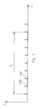
- Figure 1 schematically depicts the transmission T of several messages or signal packets 100 by a transmitter in a RF band having a transmission time limitation as a function of time t.
- the transmission time limitation can e.g. be expressed as a maximum transmission time (i.e. the accumulated time to transmit the signals 100) over a period TL.
- TL can e.g. be a period of 1 hour, during which hour the maximum transmission time is e.g. 1 %, or 36 sec.
- an average transmission delay can be determined from the transmission time limitation. In case signals of 4 ms are to be sent, the average transmission delay (i.e. the time between the transmission of two consecutive signals) should be 400 ms, in order to meet the transmission time limitation.
- a transmission with a shorter delay than the average transmission delay can be allowed when a time credit has been build up or when a negative time credit is build up.
- Such time credit can be build up during a period when the transmitter is not used or is used less than allowed, on average, by the transmission time limitation.
- a possible transmission schedule as can be realised with the present invention, is schematically shown in figure 2 .
- Figure 2 schematically depicts the transmission T of a plurality of signal packets 200 by an RF transmitter.
- Figure 2 also depicts the average transmission delay Ta as can be derived from the signal duration and the transmission time limitation (Ta e.g. being equal to 400 ms in case 4 ms signals are to be transmitted and an average transmission duty cycle of 1% being allowed).
- Ta e.g. being equal to 400 ms in case 4 ms signals are to be transmitted and an average transmission duty cycle of 1% being allowed.
- T1 e.g. being equal to 400 ms in case 4 ms signals are to be transmitted and an average transmission duty cycle of 1% being allowed.
- T1 e.g. being passed, during which, no transmission has occurred.
- a time credit has been build-up (e.g. in a linear manner). This can e.g. be realised in a processing unit of the user interface comprising the transmitter.
- the time credit is applied to allow signal packets being sent at a higher rate than allowed by the average transmission delay. This is done by determining a delay Td for the transmission of the signals based on the available time credit.
- a delay Td for the transmission of a signal can be set to Ta/2 as long as the available time credit is larger or equal to Ta/2.
- the delay Td can be set to a fixed value which is based on an average / normal response time of the user. Such a user response time can be determined based on experiments.
- a user response time can be predetermined and used as a fixed value for the delay, provided there is sufficient time credit.
- the delay Td can be set to 200 ms.
- Signal packets can be transmitter by the RF transmitter with a delay of 200 ms as long as a time credit larger than Ta-200 ms is available.
- the predetermined response time can be selected to correspond to a required response time corresponding to the delay between consecutive events, e.g. control signals from a separate control unit. In case such control unit may require the transmission of signal packets separated by a predetermined response time (this response time can e.g. be substantially smaller than normal user response time), such transmission can be possible when the required time credit is available.
- the transmission of two consecutive signals is to take place with a delay Td2 that can be longer than the average transmission delay, in order to comply with the transmission time limitation.
- Td2 a delay that can be longer than the average transmission delay
- the transmission delay as applied when no credit is available needs to be larger that the average transmission delay, in order not the exceed the average transmission delay Ta as allowed during the period TL.
- the required increase in transmission delay may easily be calculated from the time credit and the manner this time credit is applied to reduce the transmission delay.
- the time-credit should be limited.
- the time credit generation may e.g. be realised in a linear manner during a passed first period (e.g. 18 seconds) to a maximum time credit TCmax.
- the time credit may e.g. be reduced with a period equal to the average transmission delay for each signal packet transmitted.
- Figure 2 schematically depicts the build-up and reduction of the time credit corresponding to the transmission schedule of figure 2 (upper curve).
- a linear increase of the time credit has taken place when during the passed first period T1 no transmission was performed.
- the first period T1 need not be a fixed period in time but should preferable move along.
- the accumulated signal transmission time thus being determined over the latest first period that has passed.
- the transmission of a number of signal packets is required (e.g. by a user operating the user interface).
- the signal packets can be transmitted with a smaller than average transmission delay, as long as a sufficient amount of time credit is available (either positive or negative).
- the time credit is reduced (stepwise) with the appropriate amount (e.g. the average transmission delay minus the actual delay).
- the applied delay Td2 is determined to comply with the transmission time limitation. This may require a larger than average transmission delay, in order to meet the transmission time limitation.
- the accumulated transmission time over the passed period equal to TL can be used. From this accumulated transmission time and the maximum transmission time over a period TL, it can be determined whether or not a signal can be transmitted. When the application by the user of the user interface (i.e. the transmission of signals) is stopped prior to the time credit being equal to zero, the time credit can be increased again.
- the increase of the time credit can, as will be acknowledged by the skilled person, be implemented in various ways.
- the time credit can e.g. increase in a linear manner when no transmission is required.
- the time credit can be incremented with a certain value (e.g. the average transmission delay) each time a certain period (e.g. a fraction of the first period) has lapsed without a signal being transmitted.
- the time credit may also derived from a comparison of the actual transmission during the passed first period and the allowable transmission during such a first period assuming a uniform transmission schedule (as e.g. illustrated in figure 1 ).
- a time credit can be assigned based on the difference.
- the time credit may equally be implemented as a time debit (or negative time credit) allowing a user to transmit signal packets at a comparatively high duty cycle during a certain period, whereas the accumulated time debit needs to be compensated later on to comply with the transmission time limitation.
- the method according to the invention may advantageously be applied in a remote control user interface for a lighting system for controlling one or more light fixtures of the lighting system.
- Control of said light fixtures can e.g. include controlling the intensity of the light, or the colour.
- the lighting system may thus comprise a remote control user interface for providing control signals (as signal packets) to the light fixtures; the user interface thereto being equipped with an RF transmitter for transmitting the signal packets and the light fixtures being equipped with a receiver for receiving the signal packets.
- the remote control user interface may comprise a processing unit.
- the processing unit may further comprise a memory unit (preferably a non-volatile memory unit) for storing the time credit.
- the actual transmission pattern over the first period is stored in the memory unit. By doing so, the accumulated transmission during the first period may easily be monitored. It may be advantageous to keep the first period to a comparatively small value, e.g. 60 seconds or less, preferably 20 seconds. By doing so, the memory unit applied to store the actual transmission pattern can remain comparatively small.
- the processing unit may further be equipped with a timer or a counter for monitoring the actual transmission over the first period.
- the first period corresponds to the time that has lapsed since the last transmission. As soon as this period is larger than the average transmission delay, as can be determined from the transmission time limitation, the additional time can be stored as time credit. As soon as this credit is available, it can be applied to allow transmissions of signal packets with a delay that is smaller than the average transmission delay.
- the remote control user interface according to the invention can advantageously be applied in a lighting system according to the invention, the lighting system comprising a remote control user interface according to the invention and a light fixture comprising a receiver for receiving a control signal transmitted by the remote control user interface.
- the control signal can e.g. be transmitted by the remote control user interface in response to a user operation of the interface.
- the control signal can, as an example, comprise a set point or instruction for the light fixture (e.g. processed by control unit of the light fixture) to set or modify an illumination parameter (e.g. a colour or an intensity) of the light fixture.
- the light fixture comprises an LED unit comprising one or more LEDs, a power converter such as a switched mode power supply for providing power to the LED unit and a control unit arranged to receive the control signal from the receiver (e.g. via an input terminal), process the control signal and control the LED unit and/or the power converter in order to e.g. obtain the desired illumination parameter (e.g. by providing the processed control signal to the LED unit or power converter via an output terminal).
- the control unit is arranged to control the light fixture in accordance with the signal until a next signal is received.
- signals for controlling the LED units are often provided to the light fixtures in a substantially continuous manner.
- control unit of the light fixture as applied in an embodiment of the lighting system according to the invention does not require a continuous provision of a signal to control the light fixture. Instead, the control unit continues to apply the signal that was last received as an input to control the LED unit and/or power converter, until a next signal is received.
- a single processor, processing unit, control unit or other unit may fulfil the functions of several items recited in the claims.
Landscapes
- Engineering & Computer Science (AREA)
- Computer Networks & Wireless Communication (AREA)
- Physics & Mathematics (AREA)
- General Physics & Mathematics (AREA)
- Circuit Arrangement For Electric Light Sources In General (AREA)
Claims (15)
- Verfahren zum Senden eines Signalpaketes (100, 200) durch einen HF-Sender einer Fernsteuer-Benutzerschnittstelle in einem HF-Band, das eine Sendezeitbegrenzung hat, wobei das Verfahren gekennzeichnet ist durch:- Bestimmen eines Zeitguthabens aus einer akkumulierten Signalsendezeit des HF-Senders während einer ersten Periode (T1);- Bestimmen einer Verzögerung (Td) für die Sendung des Signalpaketes (100, 200) um der Sendezeitbegrenzung mit Hilfe des Zeitguthabens gerecht zu werden; und- Senden des Signalpaketes (100, 200) unter Berücksichtigung der Verzögerung (Td).
- Verfahren nach Anspruch 1, bei dem die Verzögerung (Td) aus einer durchschnittlichen Sendeverzögerung (Ta) in dem HF-Band und dem Zeitguthaben bestimmt wird.
- Verfahren nach Anspruch 2, bei dem die Verzögerung im wesentlichen einer vorbestimmten Antwortzeit entspricht, wenn das Zeitguthaben größer ist als die durchschnittliche Sendeverzögerung (Ta) minus der vorbestimmten Benutzerantwortzeit.
- Verfahren nach Anspruch 1 oder 2, bei dem die Sendezeitbegrenzung eine maximale Sendezeit während einer zweiten Periode umfasst.
- Verfahren nach einem der vorherigen Ansprüche, bei dem das Zeitguthaben aus einer akkumulierten Sendung während der ersten Periode (T1) bestimmt wird.
- Verfahren nach Anspruch 2, bei dem die Verzögerung (Td) größer ist als die durchschnittliche Sendeverzögerung (Ta), wenn das Zeitguthaben gleich null ist.
- Verfahren nach einem der vorhergehenden Ansprüche, bei dem das Zeitguthaben auf ein maximales Zeitguthaben beschränkt ist.
- Verfahren nach einem der vorhergehenden Ansprüche, bei dem die erste Periode (T1) geringer als 60 Sekunden ist.
- Verfahren nach Anspruch 4, bei dem die Verzögerung (Td) aus einer akkumulierten Sendezeit (Ta) während der vergangenen zweiten Periode bestimmt wird, wenn das Zeitguthaben gleich null ist.
- Fernsteuer-Benutzerschnittstelle für ein Beleuchtungssystem, wobei die Benutzerschnittstelle einen HF-Sender zum Senden eines Signalpaketes (100, 200) zum Steuern des Beleuchtungssystems umfasst und der Sender dazu eingerichtet ist, in einem HF-Band zu senden, das eine Sendezeitbegrenzung hat,
dadurch gekennzeichnet, dass die Benutzerschnittstelle eine Verarbeitungseinheit umfasst, die dazu eingerichtet ist:- ein Zeitguthaben aus einer Sendung des HF-Senders während einer vergangenen ersten Periode (T1) zu bestimmen;- eine Verzögerung (Td) für die Sendung des Signalpaketes (100, 200) zu bestimmen, um der Sendezeitbegrenzung mit Hilfe des Zeitguthabens gerecht zu werden, und- den HF-Sender derart zu steuern, dass er das Signalpaket (100, 200) unter Berücksichtigung der Zeitverzögerung (Td) sendet. - Fernsteuer-Benutzerschnittstelle nach Anspruch 10, bei der die Verzögerung (Td) aus einer durchschnittlichen Sendeverzögerung (Ta) in dem HF-Band und dem Zeitguthaben bestimmt wird.
- Fernsteuer-Benutzerschnittstelle nach Anspruch 10, bei der die Verzögerung (Td) im wesentlichen einer vorbestimmten Benutzerantwortzeit entspricht, wenn das Zeitguthaben größer ist als die durchschnittliche Sendeverzögerung (Ta) minus der vorbestimmten Benutzerantwortzeit.
- Beleuchtungssystem, umfassend eine Fernsteuer-Benutzerschnittstelle nach einem der Ansprüche 10 bis 12 und eine Beleuchtungseinrichtung, die dazu eingerichtet ist, das Signal (100, 200) von der Fernsteuer-Benutzerschnittstelle zu empfangen.
- Beleuchtungssystem nach Anspruch 13, bei dem die Beleuchtungseinrichtung umfasst:- einen Empfänger zum Empfangen des Signals (100, 200);- eine LED-Einheit, die wenigstens eine LED umfasst;- einen Stromwandler zum Versorgen der LED-Einheit mit Strom und- eine Steuereinheit, die einen Eingangsanschluss zum Empfangen des Signals (100, 200) von dem Empfänger umfasst, wobei die Steuereinheit dazu eingerichtet ist, das Signal zu einem Steuersignal zu verarbeiten und das Steuersignal über einen Ausgangsanschluss der LED-Einheit und/oder dem Stromwandler bereitzustellen, um die Beleuchtungseinrichtung gemäß dem Signal zu steuern.
- Beleuchtungssystem nach Anspruch 14, bei dem die Steuereinheit dazu eingerichtet ist, die Beleuchtungseinrichtung gemäß dem Signal (100, 200) zu steuern, bis ein nächstes Signal von der Fernsteuer-Benutzerschnittstelle empfangen wird.
Applications Claiming Priority (2)
| Application Number | Priority Date | Filing Date | Title |
|---|---|---|---|
| US9310208P | 2008-08-29 | 2008-08-29 | |
| PCT/NL2009/000166 WO2010024665A1 (en) | 2008-08-29 | 2009-08-27 | Method of transmitting a signal packet by an rf transmitter of a remote control user interface and a remote control unit for a lighting system comprising an rf transmitter |
Publications (2)
| Publication Number | Publication Date |
|---|---|
| EP2332395A1 EP2332395A1 (de) | 2011-06-15 |
| EP2332395B1 true EP2332395B1 (de) | 2014-06-25 |
Family
ID=41168540
Family Applications (1)
| Application Number | Title | Priority Date | Filing Date |
|---|---|---|---|
| EP09788152.8A Active EP2332395B1 (de) | 2008-08-29 | 2009-08-27 | Verfahren zum senden eines signalpakets durch einen hf-sender einer fernbedienungs-benutzeroberfläche und fernbedienungseinheit für ein beleuchtungssystem mit einem hf-sender |
Country Status (2)
| Country | Link |
|---|---|
| EP (1) | EP2332395B1 (de) |
| WO (1) | WO2010024665A1 (de) |
Families Citing this family (1)
| Publication number | Priority date | Publication date | Assignee | Title |
|---|---|---|---|---|
| JP6185562B2 (ja) * | 2012-04-27 | 2017-08-23 | フィリップス ライティング ホールディング ビー ヴィ | 無線ネットワークにおけるデューティサイクル制御 |
Family Cites Families (3)
| Publication number | Priority date | Publication date | Assignee | Title |
|---|---|---|---|---|
| US5905442A (en) * | 1996-02-07 | 1999-05-18 | Lutron Electronics Co., Inc. | Method and apparatus for controlling and determining the status of electrical devices from remote locations |
| US7536194B2 (en) * | 2005-09-30 | 2009-05-19 | Robert Bosch Gmbh | Method and system for providing an energy efficient exchange of information in wireless networks |
| US7573208B2 (en) * | 2007-03-05 | 2009-08-11 | Lutron Electronics Co., Inc. | Method of programming a lighting preset from a radio-frequency remote control |
-
2009
- 2009-08-27 EP EP09788152.8A patent/EP2332395B1/de active Active
- 2009-08-27 WO PCT/NL2009/000166 patent/WO2010024665A1/en not_active Ceased
Also Published As
| Publication number | Publication date |
|---|---|
| WO2010024665A1 (en) | 2010-03-04 |
| EP2332395A1 (de) | 2011-06-15 |
Similar Documents
| Publication | Publication Date | Title |
|---|---|---|
| JP5893409B2 (ja) | 照明システムを制御する方法 | |
| JP5956027B2 (ja) | 高出力led群の動作方法および装置 | |
| US8463454B2 (en) | Wireless ballast control unit | |
| JP6508597B2 (ja) | 照明コントローラ、及び照明器具の制御方法 | |
| EP2329687B1 (de) | Konfigurierbare lichtbefestigungsvorrichtung, konfigurierbares beleuchtungssystem und verfahren zum konfigurieren eines beleuchtungssystems | |
| JP5615916B2 (ja) | 半被同期ポインティングのためのプッシュビット | |
| US20090206983A1 (en) | Communication System for a Radio-Frequency Load Control System | |
| JP2007502529A (ja) | Rf制御式照明システム用システムブリッジ及びタイムクロック | |
| AU2005316790A1 (en) | Distributed intelligence ballast system and extended lighting control protocol | |
| CN102483879B (zh) | 远程控制器以及利用其从多个光源中选择光源的方法 | |
| US9304051B2 (en) | Smart sensor unit with memory metal antenna | |
| CN101958742B (zh) | 用于强电组件的中继转发控制系统及无线控制装置 | |
| EP2332395B1 (de) | Verfahren zum senden eines signalpakets durch einen hf-sender einer fernbedienungs-benutzeroberfläche und fernbedienungseinheit für ein beleuchtungssystem mit einem hf-sender | |
| EP2910089B1 (de) | Vorrichtung und verfahren zum interpretieren von empfangenen steuerbefehlen | |
| US20170055332A1 (en) | Illumination system | |
| JP2018110089A (ja) | 照明制御システム、照明制御方法、制御装置及び制御方法 | |
| KR101700441B1 (ko) | 복수의 디바이스의 원격 제어 | |
| WO2024083709A1 (en) | Networked lighting system | |
| US10652986B1 (en) | Dimmer system control | |
| EP3574714B1 (de) | Zur steuerung über ein drahtloses steuergerät angeordnete beleuchtungsvorrichtung | |
| JP5186261B2 (ja) | 無線式調光制御システム | |
| EP2466971A1 (de) | Router und Betriebsverfahren für den Router | |
| JP6985093B2 (ja) | 灯具制御装置 | |
| JP2019515418A (ja) | 少なくとも1つの発光体を動作させるための動作回路および方法 | |
| JP2000196526A (ja) | 赤外線送信装置 |
Legal Events
| Date | Code | Title | Description |
|---|---|---|---|
| PUAI | Public reference made under article 153(3) epc to a published international application that has entered the european phase |
Free format text: ORIGINAL CODE: 0009012 |
|
| 17P | Request for examination filed |
Effective date: 20110324 |
|
| AK | Designated contracting states |
Kind code of ref document: A1 Designated state(s): AT BE BG CH CY CZ DE DK EE ES FI FR GB GR HR HU IE IS IT LI LT LU LV MC MK MT NL NO PL PT RO SE SI SK SM TR |
|
| AX | Request for extension of the european patent |
Extension state: AL BA RS |
|
| DAX | Request for extension of the european patent (deleted) | ||
| GRAP | Despatch of communication of intention to grant a patent |
Free format text: ORIGINAL CODE: EPIDOSNIGR1 |
|
| INTG | Intention to grant announced |
Effective date: 20140228 |
|
| GRAS | Grant fee paid |
Free format text: ORIGINAL CODE: EPIDOSNIGR3 |
|
| GRAA | (expected) grant |
Free format text: ORIGINAL CODE: 0009210 |
|
| AK | Designated contracting states |
Kind code of ref document: B1 Designated state(s): AT BE BG CH CY CZ DE DK EE ES FI FR GB GR HR HU IE IS IT LI LT LU LV MC MK MT NL NO PL PT RO SE SI SK SM TR |
|
| REG | Reference to a national code |
Ref country code: GB Ref legal event code: FG4D |
|
| REG | Reference to a national code |
Ref country code: CH Ref legal event code: EP |
|
| REG | Reference to a national code |
Ref country code: AT Ref legal event code: REF Ref document number: 675352 Country of ref document: AT Kind code of ref document: T Effective date: 20140715 |
|
| REG | Reference to a national code |
Ref country code: IE Ref legal event code: FG4D |
|
| REG | Reference to a national code |
Ref country code: DE Ref legal event code: R096 Ref document number: 602009024959 Country of ref document: DE Effective date: 20140807 |
|
| REG | Reference to a national code |
Ref country code: NL Ref legal event code: T3 |
|
| PG25 | Lapsed in a contracting state [announced via postgrant information from national office to epo] |
Ref country code: LT Free format text: LAPSE BECAUSE OF FAILURE TO SUBMIT A TRANSLATION OF THE DESCRIPTION OR TO PAY THE FEE WITHIN THE PRESCRIBED TIME-LIMIT Effective date: 20140625 Ref country code: FI Free format text: LAPSE BECAUSE OF FAILURE TO SUBMIT A TRANSLATION OF THE DESCRIPTION OR TO PAY THE FEE WITHIN THE PRESCRIBED TIME-LIMIT Effective date: 20140625 Ref country code: NO Free format text: LAPSE BECAUSE OF FAILURE TO SUBMIT A TRANSLATION OF THE DESCRIPTION OR TO PAY THE FEE WITHIN THE PRESCRIBED TIME-LIMIT Effective date: 20140925 Ref country code: CY Free format text: LAPSE BECAUSE OF FAILURE TO SUBMIT A TRANSLATION OF THE DESCRIPTION OR TO PAY THE FEE WITHIN THE PRESCRIBED TIME-LIMIT Effective date: 20140625 Ref country code: GR Free format text: LAPSE BECAUSE OF FAILURE TO SUBMIT A TRANSLATION OF THE DESCRIPTION OR TO PAY THE FEE WITHIN THE PRESCRIBED TIME-LIMIT Effective date: 20140926 |
|
| REG | Reference to a national code |
Ref country code: AT Ref legal event code: MK05 Ref document number: 675352 Country of ref document: AT Kind code of ref document: T Effective date: 20140625 |
|
| REG | Reference to a national code |
Ref country code: LT Ref legal event code: MG4D |
|
| PG25 | Lapsed in a contracting state [announced via postgrant information from national office to epo] |
Ref country code: LV Free format text: LAPSE BECAUSE OF FAILURE TO SUBMIT A TRANSLATION OF THE DESCRIPTION OR TO PAY THE FEE WITHIN THE PRESCRIBED TIME-LIMIT Effective date: 20140625 Ref country code: SE Free format text: LAPSE BECAUSE OF FAILURE TO SUBMIT A TRANSLATION OF THE DESCRIPTION OR TO PAY THE FEE WITHIN THE PRESCRIBED TIME-LIMIT Effective date: 20140625 Ref country code: HR Free format text: LAPSE BECAUSE OF FAILURE TO SUBMIT A TRANSLATION OF THE DESCRIPTION OR TO PAY THE FEE WITHIN THE PRESCRIBED TIME-LIMIT Effective date: 20140625 |
|
| PG25 | Lapsed in a contracting state [announced via postgrant information from national office to epo] |
Ref country code: CZ Free format text: LAPSE BECAUSE OF FAILURE TO SUBMIT A TRANSLATION OF THE DESCRIPTION OR TO PAY THE FEE WITHIN THE PRESCRIBED TIME-LIMIT Effective date: 20140625 Ref country code: EE Free format text: LAPSE BECAUSE OF FAILURE TO SUBMIT A TRANSLATION OF THE DESCRIPTION OR TO PAY THE FEE WITHIN THE PRESCRIBED TIME-LIMIT Effective date: 20140625 Ref country code: SK Free format text: LAPSE BECAUSE OF FAILURE TO SUBMIT A TRANSLATION OF THE DESCRIPTION OR TO PAY THE FEE WITHIN THE PRESCRIBED TIME-LIMIT Effective date: 20140625 Ref country code: PT Free format text: LAPSE BECAUSE OF FAILURE TO SUBMIT A TRANSLATION OF THE DESCRIPTION OR TO PAY THE FEE WITHIN THE PRESCRIBED TIME-LIMIT Effective date: 20141027 Ref country code: RO Free format text: LAPSE BECAUSE OF FAILURE TO SUBMIT A TRANSLATION OF THE DESCRIPTION OR TO PAY THE FEE WITHIN THE PRESCRIBED TIME-LIMIT Effective date: 20140625 Ref country code: ES Free format text: LAPSE BECAUSE OF FAILURE TO SUBMIT A TRANSLATION OF THE DESCRIPTION OR TO PAY THE FEE WITHIN THE PRESCRIBED TIME-LIMIT Effective date: 20140625 |
|
| PG25 | Lapsed in a contracting state [announced via postgrant information from national office to epo] |
Ref country code: PL Free format text: LAPSE BECAUSE OF FAILURE TO SUBMIT A TRANSLATION OF THE DESCRIPTION OR TO PAY THE FEE WITHIN THE PRESCRIBED TIME-LIMIT Effective date: 20140625 Ref country code: AT Free format text: LAPSE BECAUSE OF FAILURE TO SUBMIT A TRANSLATION OF THE DESCRIPTION OR TO PAY THE FEE WITHIN THE PRESCRIBED TIME-LIMIT Effective date: 20140625 Ref country code: IS Free format text: LAPSE BECAUSE OF FAILURE TO SUBMIT A TRANSLATION OF THE DESCRIPTION OR TO PAY THE FEE WITHIN THE PRESCRIBED TIME-LIMIT Effective date: 20141025 |
|
| REG | Reference to a national code |
Ref country code: DE Ref legal event code: R097 Ref document number: 602009024959 Country of ref document: DE |
|
| PG25 | Lapsed in a contracting state [announced via postgrant information from national office to epo] |
Ref country code: LU Free format text: LAPSE BECAUSE OF FAILURE TO SUBMIT A TRANSLATION OF THE DESCRIPTION OR TO PAY THE FEE WITHIN THE PRESCRIBED TIME-LIMIT Effective date: 20140827 Ref country code: MC Free format text: LAPSE BECAUSE OF FAILURE TO SUBMIT A TRANSLATION OF THE DESCRIPTION OR TO PAY THE FEE WITHIN THE PRESCRIBED TIME-LIMIT Effective date: 20140625 |
|
| REG | Reference to a national code |
Ref country code: CH Ref legal event code: PL |
|
| PG25 | Lapsed in a contracting state [announced via postgrant information from national office to epo] |
Ref country code: LI Free format text: LAPSE BECAUSE OF NON-PAYMENT OF DUE FEES Effective date: 20140831 Ref country code: BE Free format text: LAPSE BECAUSE OF NON-PAYMENT OF DUE FEES Effective date: 20140831 Ref country code: DK Free format text: LAPSE BECAUSE OF FAILURE TO SUBMIT A TRANSLATION OF THE DESCRIPTION OR TO PAY THE FEE WITHIN THE PRESCRIBED TIME-LIMIT Effective date: 20140625 Ref country code: CH Free format text: LAPSE BECAUSE OF NON-PAYMENT OF DUE FEES Effective date: 20140831 Ref country code: IT Free format text: LAPSE BECAUSE OF FAILURE TO SUBMIT A TRANSLATION OF THE DESCRIPTION OR TO PAY THE FEE WITHIN THE PRESCRIBED TIME-LIMIT Effective date: 20140625 |
|
| PLBE | No opposition filed within time limit |
Free format text: ORIGINAL CODE: 0009261 |
|
| STAA | Information on the status of an ep patent application or granted ep patent |
Free format text: STATUS: NO OPPOSITION FILED WITHIN TIME LIMIT |
|
| REG | Reference to a national code |
Ref country code: IE Ref legal event code: MM4A |
|
| 26N | No opposition filed |
Effective date: 20150326 |
|
| PG25 | Lapsed in a contracting state [announced via postgrant information from national office to epo] |
Ref country code: BE Free format text: LAPSE BECAUSE OF FAILURE TO SUBMIT A TRANSLATION OF THE DESCRIPTION OR TO PAY THE FEE WITHIN THE PRESCRIBED TIME-LIMIT Effective date: 20140625 |
|
| PG25 | Lapsed in a contracting state [announced via postgrant information from national office to epo] |
Ref country code: IE Free format text: LAPSE BECAUSE OF NON-PAYMENT OF DUE FEES Effective date: 20140827 |
|
| PG25 | Lapsed in a contracting state [announced via postgrant information from national office to epo] |
Ref country code: SI Free format text: LAPSE BECAUSE OF FAILURE TO SUBMIT A TRANSLATION OF THE DESCRIPTION OR TO PAY THE FEE WITHIN THE PRESCRIBED TIME-LIMIT Effective date: 20140625 |
|
| PG25 | Lapsed in a contracting state [announced via postgrant information from national office to epo] |
Ref country code: SM Free format text: LAPSE BECAUSE OF FAILURE TO SUBMIT A TRANSLATION OF THE DESCRIPTION OR TO PAY THE FEE WITHIN THE PRESCRIBED TIME-LIMIT Effective date: 20140625 |
|
| PG25 | Lapsed in a contracting state [announced via postgrant information from national office to epo] |
Ref country code: MT Free format text: LAPSE BECAUSE OF FAILURE TO SUBMIT A TRANSLATION OF THE DESCRIPTION OR TO PAY THE FEE WITHIN THE PRESCRIBED TIME-LIMIT Effective date: 20140625 Ref country code: BG Free format text: LAPSE BECAUSE OF FAILURE TO SUBMIT A TRANSLATION OF THE DESCRIPTION OR TO PAY THE FEE WITHIN THE PRESCRIBED TIME-LIMIT Effective date: 20140625 |
|
| PG25 | Lapsed in a contracting state [announced via postgrant information from national office to epo] |
Ref country code: TR Free format text: LAPSE BECAUSE OF FAILURE TO SUBMIT A TRANSLATION OF THE DESCRIPTION OR TO PAY THE FEE WITHIN THE PRESCRIBED TIME-LIMIT Effective date: 20140625 Ref country code: HU Free format text: LAPSE BECAUSE OF FAILURE TO SUBMIT A TRANSLATION OF THE DESCRIPTION OR TO PAY THE FEE WITHIN THE PRESCRIBED TIME-LIMIT; INVALID AB INITIO Effective date: 20090827 |
|
| REG | Reference to a national code |
Ref country code: FR Ref legal event code: PLFP Year of fee payment: 8 |
|
| REG | Reference to a national code |
Ref country code: FR Ref legal event code: PLFP Year of fee payment: 9 |
|
| PG25 | Lapsed in a contracting state [announced via postgrant information from national office to epo] |
Ref country code: MK Free format text: LAPSE BECAUSE OF FAILURE TO SUBMIT A TRANSLATION OF THE DESCRIPTION OR TO PAY THE FEE WITHIN THE PRESCRIBED TIME-LIMIT Effective date: 20140625 |
|
| REG | Reference to a national code |
Ref country code: FR Ref legal event code: PLFP Year of fee payment: 10 |
|
| PGFP | Annual fee paid to national office [announced via postgrant information from national office to epo] |
Ref country code: NL Payment date: 20250825 Year of fee payment: 17 |
|
| PGFP | Annual fee paid to national office [announced via postgrant information from national office to epo] |
Ref country code: DE Payment date: 20250819 Year of fee payment: 17 |
|
| PGFP | Annual fee paid to national office [announced via postgrant information from national office to epo] |
Ref country code: GB Payment date: 20250822 Year of fee payment: 17 |
|
| PGFP | Annual fee paid to national office [announced via postgrant information from national office to epo] |
Ref country code: FR Payment date: 20250821 Year of fee payment: 17 |