EP2332501B1 - Instrument zum einsetzen von intraokularlinsen - Google Patents
Instrument zum einsetzen von intraokularlinsen Download PDFInfo
- Publication number
- EP2332501B1 EP2332501B1 EP09811445.7A EP09811445A EP2332501B1 EP 2332501 B1 EP2332501 B1 EP 2332501B1 EP 09811445 A EP09811445 A EP 09811445A EP 2332501 B1 EP2332501 B1 EP 2332501B1
- Authority
- EP
- European Patent Office
- Prior art keywords
- intraocular lens
- lens
- operation portion
- main body
- insertion device
- Prior art date
- Legal status (The legal status is an assumption and is not a legal conclusion. Google has not performed a legal analysis and makes no representation as to the accuracy of the status listed.)
- Active
Links
Images


Classifications
-
- A—HUMAN NECESSITIES
- A61—MEDICAL OR VETERINARY SCIENCE; HYGIENE
- A61F—FILTERS IMPLANTABLE INTO BLOOD VESSELS; PROSTHESES; DEVICES PROVIDING PATENCY TO, OR PREVENTING COLLAPSING OF, TUBULAR STRUCTURES OF THE BODY, e.g. STENTS; ORTHOPAEDIC, NURSING OR CONTRACEPTIVE DEVICES; FOMENTATION; TREATMENT OR PROTECTION OF EYES OR EARS; BANDAGES, DRESSINGS OR ABSORBENT PADS; FIRST-AID KITS
- A61F2/00—Filters implantable into blood vessels; Prostheses, i.e. artificial substitutes or replacements for parts of the body; Appliances for connecting them with the body; Devices providing patency to, or preventing collapsing of, tubular structures of the body, e.g. stents
- A61F2/02—Prostheses implantable into the body
- A61F2/14—Eye parts, e.g. lenses or corneal implants; Artificial eyes
- A61F2/16—Intraocular lenses
- A61F2/1662—Instruments for inserting intraocular lenses into the eye
- A61F2/1678—Instruments for inserting intraocular lenses into the eye with a separate cartridge or other lens setting part for storage of a lens, e.g. preloadable for shipping
-
- A—HUMAN NECESSITIES
- A61—MEDICAL OR VETERINARY SCIENCE; HYGIENE
- A61F—FILTERS IMPLANTABLE INTO BLOOD VESSELS; PROSTHESES; DEVICES PROVIDING PATENCY TO, OR PREVENTING COLLAPSING OF, TUBULAR STRUCTURES OF THE BODY, e.g. STENTS; ORTHOPAEDIC, NURSING OR CONTRACEPTIVE DEVICES; FOMENTATION; TREATMENT OR PROTECTION OF EYES OR EARS; BANDAGES, DRESSINGS OR ABSORBENT PADS; FIRST-AID KITS
- A61F2/00—Filters implantable into blood vessels; Prostheses, i.e. artificial substitutes or replacements for parts of the body; Appliances for connecting them with the body; Devices providing patency to, or preventing collapsing of, tubular structures of the body, e.g. stents
- A61F2/02—Prostheses implantable into the body
- A61F2/14—Eye parts, e.g. lenses or corneal implants; Artificial eyes
- A61F2/16—Intraocular lenses
- A61F2/1662—Instruments for inserting intraocular lenses into the eye
- A61F2/1672—Instruments for inserting intraocular lenses into the eye with a two-stage plunger, e.g. rotatable and pushable or rotatable at different speeds
-
- A—HUMAN NECESSITIES
- A61—MEDICAL OR VETERINARY SCIENCE; HYGIENE
- A61F—FILTERS IMPLANTABLE INTO BLOOD VESSELS; PROSTHESES; DEVICES PROVIDING PATENCY TO, OR PREVENTING COLLAPSING OF, TUBULAR STRUCTURES OF THE BODY, e.g. STENTS; ORTHOPAEDIC, NURSING OR CONTRACEPTIVE DEVICES; FOMENTATION; TREATMENT OR PROTECTION OF EYES OR EARS; BANDAGES, DRESSINGS OR ABSORBENT PADS; FIRST-AID KITS
- A61F2/00—Filters implantable into blood vessels; Prostheses, i.e. artificial substitutes or replacements for parts of the body; Appliances for connecting them with the body; Devices providing patency to, or preventing collapsing of, tubular structures of the body, e.g. stents
- A61F2/02—Prostheses implantable into the body
- A61F2/14—Eye parts, e.g. lenses or corneal implants; Artificial eyes
- A61F2/16—Intraocular lenses
- A61F2/1662—Instruments for inserting intraocular lenses into the eye
- A61F2/167—Instruments for inserting intraocular lenses into the eye with pushable plungers
Definitions
- the present invention relates to an intraocular lens insertion device for inserting an intraocular lens into an aphakic eye after cataract surgery or into a phakic eye at the time of refractive surgery.
- intraocular lens that can be inserted through a small incision has been available and often used in the clinical setting as phacoemulsification technology prevails, such intraocular lens being provided for alleviating post-surgical astigmatism and invasiveness of surgical procedures, and made of soft materials such as foldable silicon, acrylic resin, hydrogel or the like.
- intraocular lens insertion devices for inserting such foldable intraocular lens through a smaller incision on an eye ball.
- an intraocular lens folded small is allowed to be pushed out and into an eye through an insertion tube having a cylindrical shape, thus making it possible to insert the intraocular lens into the eye through a significantly smaller incision as compared to a conventional case requiring a pair of tweezers to be used for insertion.
- Insertion methods of the intraocular lens insertion devices are broadly divided into a group of screw-type (screw style) and a group of push-type.
- a push-type intraocular lens insertion device allows an operator to sensuously press an operation portion with his/her grip strength against resistance such as friction or the like between the intraocular lens and an inner wall of the insertion tube, and allows a pressure thus applied to be transmitted to the intraocular lens so as to push the same forward (e.g., see patent documents 1, 2, 3).
- an insertion operation of the intraocular lens is not only simple, but can be performed with one hand, thereby allowing the operator to use his/her free hand to perform other operations when performing the insertion operation.
- the intraocular lens needs to be moved forward while balancing the friction resistance between the intraocular lens and the inner wall of the insertion tube with the pressure applied to the operation portion, thus making it relatively difficult to control the pressure applied to the operation portion.
- a nozzle provided on a distal end of the intraocular lens insertion device is the narrowest portion in the insertion tube through which the intraocular lens passes. In this sense, a load generated as the intraocular lens passes through the nozzle becomes large, particularly when releasing an intraocular lens with high power therefrom and when an inner diameter of the nozzle is made small so as to match a smaller incision. Therefore, there is a possibility that the intraocular lens may be abruptly released into the eye, and that eye tissue may thus be damaged.
- a screw-type intraocular lens insertion device comprises a plunger and a main body that are screwed together like an external thread and an internal thread.
- Such screw-type intraocular lens insertion device allows the plunger and a rod for pushing the intraocular lens to move to a lens advancement direction when an operation portion on an end portion of the plunger is twisted (e.g., see patent document 4).
- it is easy to control moving amounts of the plunger and the rod.
- the intraocular lens can be prevented to some extent from being abruptly released into the eye, even when the load generated as the intraocular lens passes through the nozzle is large when releasing a thick intraocular lens and the inner diameter of the nozzle is made small.
- both hands are needed to perform the insertion operation, operation of the screw-type intraocular lens insertion device is relatively more troublesome than that of the push-type intraocular lens insertion device to a certain extent.
- US 2006/0085013 Al describes an intraocular lens inserter comprising predefined detent positions wherein the detent controls the motion of a mover.
- the intraocular lens is ejected from a cartridge into a patient's eye by using the predefined positions.
- EP 2 340 786 A1 describes an intraocular lens insertion device comprising a knock mechanism for moving an operation portion repeatedly forward and backward so that an intraocular lens placed in a cartridge can be pushed stepwise.
- the present invention relates to an intraocular lens insertion device as set forth in the appended claims.
- an object of the present invention to provide an intraocular lens insertion device capable of more reliably controlling the releasing of an intraocular lens into an eye.
- the invention according to a first aspect of the present invention is an intraocular lens insertion device for pushing out an intraocular lens by allowing an operation portion thereof to be pushed.
- This intraocular lens insertion device comprises: a lens contact portion for pushing out the intraocular lens; a transmitting portion for transmitting an external force applied to the operation portion to the lens contact portion; an insertion tube from which the intraocular lens is released to the outside after being pushed by the lens contact portion; and a stop means for temporarily stopping the lens contact portion as the intraocular lens passes through a vicinity of a distal end portion of the insertion tube.
- the invention according to a second aspect of the present invention is provided with a plurality of the operation portions, and is thus capable of pushing out the intraocular lens in a step-wise manner.
- the invention according to a third aspect of the present invention comprises a main body with the insertion tube fixed to a forward portion thereof, and the operation portion is provided on a backward portion thereof.
- the invention according to a fourth aspect of the present invention comprises the main body with the insertion tube fixed to the forward portion thereof, and at least one of the operation portions is provided on the backward portion thereof.
- the stop means causes the lens contact portion to be temporarily stopped at a location within 10mm from a distal end of the insertion tube.
- the stop means causes the lens contact portion to be temporarily stopped as the intraocular lens passes through a nozzle section provided on the distal end of the insertion tube.
- the stop means causes the lens contact portion to be temporarily stopped as the intraocular lens passes thorough the vicinity of the distal end portion of the insertion tube, thus allowing the lens contact portion to be stopped before the intraocular lens is released even when a large external force against a reaction force of the operation portion is applied. In this way, the intraocular lens is prevented from being abruptly released into the eye.
- the intraocular lens insertion device of the present invention is capable of releasing the intraocular lens with a small external force, thereby making it possible to more reliably control the releasing of the intraocular lens into the eye.
- the present invention is capable of lowering the possibility of abruptly releasing an intraocular lens into an eye by allowing a lens contact portion to be temporarily stopped in the vicinity of a distal end portion of an insertion tube, as compared to a case in which the lens contact portion is not stopped.
- the intraocular lens In a case in which most part of the intraocular lens has been released into the eye from a distal end of the insertion tube after temporarily stopping the lens contact portion, the intraocular lens, without being further pushed, may enter the eye on its own due to an elasticity of the distal end portion of the insertion tube portion. In this case, in order to place the intraocular lens at a predetermined location in the eye, a small force is further applied to an operation portion so as to cause the lens contact portion to move forward, thereby lowering the possibility of abruptly releasing the intraocular lens into the eye.
- the momentum of the lens contact portion moving forward can be stopped by temporarily stopping the lens contact portion, thus lowering the possibility of abruptly releasing the intraocular lens into the eye.
- the lens contact portion may be temporarily stopped at a location closer to the distal end of the insertion tube as compared to an intraocular lens insertion device in which no slit is provided on the distal end portion of the insertion tube.
- the lens contact portion may be temporarily stopped at somewhere between a location at which a pushing resistance of the operation portion reaches a maximum value and the distal end of the insertion tube.
- the location at which the lens contact portion is temporarily stopped may be determined based on a size of an optical portion of the intraocular lens. For example, when a diameter of the optical portion of the intraocular lens is 6mm, the lens contact portion is temporarily stopped beyond 6mm from the distal end of the insertion tube inwardly (from a bottom edge of a cut-out when a cut-out is formed on a nozzle section).
- a stop means for temporarily stopping the lens contact portion there can be employed a method for mechanically and forcibly stopping the lens contact portion, a means for forcibly stopping the lens contact portion through an interaction between the intraocular lens insertion device and hands or fingers operating the same, or the like.
- the operation portion may comprise a single portion pushed to temporarily stop the lens contact portion and further pushed thereafter.
- the operation portion may comprise a portion pushed to temporarily stop the lens contact portion and a portion further pushed thereafter.
- same lens contact portion is preferably used before and after being stopped.
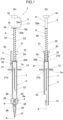
- An intraocular lens insertion device 1 shown in FIG.1 comprises a main body 2, a cartridge 4 attached to the main body 2 and an operation portion 5.
- a plunger 6 serving as a transmitting portion is connected to the operation portion 5.
- a rod 7 for pushing out an intraocular lens 8 is provided on a distal end of the plunger 6.
- the operation portion 5 is located away from one end 2a of the main body 2.
- the intraocular lens 8 placed in the cartridge 4 can be pushed out by the rod 7 as a whole as an operator pushes the operation portion 5.
- a type of disposable insertion tube that allows the operator or an assistant to place the intraocular lens 8 thereinside at the time of operation is generally called a cartridge.
- the intraocular lens insertion device 1 of the present embodiment comprises a stop means described later.
- Such stop means allows the rod 7 to first push the intraocular lens 8 by a predetermined distance and then be stopped temporarily before the intraocular lens 8 is released from the cartridge 4 toward the outside.
- a lens advancement direction (push-out direction) is referred to as a "forward direction”, while a direction opposite to this direction is referred to as a "backward direction.”
- the main body 2, the plunger 6 and the rod 7 are preferably formed by an injection-moldable synthetic resin, thus contributing to mass production thereof with low cost and favoring disposability (disposable).
- the intraocular lens 8 is made of a soft and foldable material such as silicon resin, acrylic resin, hydrogel or the like, and is unfolded after being released into an eyeball.
- the intraocular lens 8 shown in FIG. 1 is folded.
- the main body 2 is a cylindrical member.
- a restraint portion 10 serving as a stop means is provided on the one end 2a of the main body 2.
- the main body 2 has an engagement portion 11 for preventing the operation portion 5 from moving to the backward direction, an attachment groove 12 provided on an other end thereof for attaching the cartridge 4, and a finger rest 13.
- the operation portion 5 has a first operation portion 15 and a second operation portion 16.
- a spacing-keeping portion 17 is connected to proximal ends of both the first operation portion 15 and the second operation portion 16, and is provided for separating the two by a predetermined distance in the lens advancement direction.
- the operation portion 5 is formed into a tipped "U" shape by bending a substantially rectangular member, and is connected to the plunger 6 through the first operation portion 15 thereof.
- a surface located on one side of the first operation portion 15 is referred to as a first operation surface 15a.
- An engagement-receiving portion 18 is provided on a distal end of the first operation portion 15 to which the spacing-keeping portion 17 is not connected.
- the plunger 6 is capable of transmitting to the rod 7 an external force applied to the operation portion 5 in a direction of a lens advancement axis A. Further, the plunger 6 has a coil-spring-loaded rod 20 whose one end 20a is connected to an other side surface 15b of the first operation portion 15, and a movable rod 21 connected to an other end 20b of the coil-spring-loaded rod 20. The movable rod 21 is allowed to move either forward or backward inside the main body 2 in the direction of the lens advancement axis A. One end 21a of the movable rod 21 is connected to the other end 20b of the coil-spring-loaded rod 20, while an other end 21b thereof is connected to a proximal end 7a of the rod 7.
- the rod 7 is capable of pushing out the intraocular lens 8 by virtue of the external force transmitted by the plunger 6.
- a lens contact portion 22 is provided on a distal end of the rod 7.
- a heretofore known shape may be employed as the shape of the lens contact portion 22 provided on the distal end of the rod 7.
- a coil spring 23 is disposed on the coil-spring-loaded rod 20 in a manner such that while one end thereof abuts against the one end 2a of the main body 2, the other end thereof abuts against the other side surface 15b of the first operation portion 15.
- the operation portion 5 is thus biased to the backward direction due to a bias force of the coil spring 23.
- the movable rod 21 is caused to be held in a position in which it abuts against an inner wall of the one end 2a of the main body 2.
- the state in which the movable rod 21 abuts against the inner wall of the one end 2a of the main body 2 is referred to as a point of origin, for the sake of convenience in explanation.
- the cartridge 4 comprises a lens placement section 25, a transition section 26 and a nozzle section 27, all of which are successively provided along the lens advancement axis A in this order.
- the intraocular lens 8 placed in the lens placement section 25 is pushed by the rod 7 and is thus caused to move therefrom and then pass through the transition section 26.
- the intraocular lens 8 will be folded small and released as it is from the nozzle section 27 toward the outside, such nozzle section 27 having a substantially constant lumen diameter in the direction of the lens advancement axis A.
- a wing portion 28 is provided on both sides of the cartridge 4, such wing portion 28 protruding to a direction orthogonal to the lens advancement axis A.
- the wing portion 28 is so formed that it can be engaged with and fitted to the attachment groove 12 provided on the other end of the main body 2.
- a liquid such as a viscoelastic substance or the like allowing the intraocular lens 8 to move smoothly is generally injected into the cartridge 4 before attaching the same to the main body 2.
- the restraint portion 10 serves to restrain the operator's finger pushing the first operation portion 5 at a predetermined position, and the first operation portion 5 can be caused to enter the restraint portion 10. As shown in FIG.2 , one end of the restraint portion 10 is connected to the one end 2a of the main body 2, and the restraint portion 10 has an entrance groove 30 and a restraint surface 31 provided on an other end thereof.
- the restraint surface 31 is a surface orthogonal to the lens advancement axis A.
- the entrance groove 30 substantially cuts through the center of the restraint surface 31, linearly extends in a direction orthogonal to the lens advancement axis A, and is formed through the restraint portion 10 from the one end thereof to the other.
- An engagement projection 32 is formed on one end of the engagement portion 11, and is positioned on an outer edge portion where the entrance groove 30 and the restraint surface 31 intersect with one another.
- the engagement portion 11 is connected to the main body 2 through a connection plate 33 provided on an other end side of the engagement portion 11. Further, the engagement projection 32 is allowed to tilt about the connection plate 33 to a direction orthogonal to the lens advancement axis A.
- an external force in the forward direction is applied to the operation portion 5 by pushing the first operation surface 15a with fingers from a state of the point of origin of the operation portion 5 ( FIG.1 (a) ).
- the other side surface 15b of the first operation portion 15 is caused to contract the coil spring 23, thereby allowing the plunger 6 and the rod 7 to move to the forward direction.
- the first operation portion 15 arrives at the restraint portion 10, and further enters the entrance groove 30.
- an operator's finger pushing the first operation surface 15a is caused to abut against the restraint surface 31 as soon as the first operation surface 15a and the restraint surface 31 have been made flush with one another.
- the operator is no longer able to push the operation portion 5 to the forward direction any further by pushing the first operation surface 15a, thereby allowing the intraocular lens insertion device 1 to stop the lens contact portion 22 temporarily.
- the distal end of the first operation portion 15 abuts against the engagement projection 32 of the engagement portion 11. Further, the engagement portion 32 is caused to deform in a direction orthogonal to the lens advancement axis A by further pushing the first operation portion 15. Once the distal end of the first operation portion 15 has been engaged with the engagement portion 32, the engagement portion 11 will elastically return to its original shape. In this way, the engagement-receiving portion 18 of the first operation portion 15 is engaged with the engagement projection 32, thus preventing the operation portion 5 from moving to the backward direction.
- the lens contact portion 22 provided on the distal end of the rod 7 is caused to abut against a circumference of an optical portion 8a of the intraocular lens 8 placed in the cartridge 4, and push such intraocular lens 8 to the forward direction ( FIG.3 ).
- the operation portion 5 can no longer be pushed any further to the forward direction by pushing the first operation surface 15a once the first operation surface 15a and the restraint surface 31 have been made flush with one another.
- the intraocular lens insertion device 1 allows the lens contact portion 22 to be stopped temporarily as the intraocular lens 8 passes through the nozzle section 27.
- the intraocular lens 8 is allowed to be stopped at a predetermined location after moving from the lens placement section 25 to the transition section 26 and then to the nozzle section 27, successively.
- the predetermined location refers to a position where the intraocular lens 8 is about to be released from the nozzle section 27 of the cartridge 4.
- the intraocular lens 8 at such predetermined location can already be completely released toward the outside once subjected to a moderate amount of force.
- the operator applies to the operation portion 5 an external force in the forward direction by pushing the second operation portion 16.
- the first operation portion 15 is then allowed to move through the entrance groove 30 in the forward direction due to the external force applied to the operation portion 5 in the forward direction ( FIG.6 ).
- the other side surface 15b of the first operation portion 15 is caused to further contract the coil spring 23, thereby allowing the plunger 6 and the rod 7 to move to the forward direction.
- the second operation portion 16 is pushed in order to further push the operation portion 5 into the main body 2, thus allowing the lens contact portion 22 to release the intraocular lens 8 from the nozzle section 27 toward the outside ( FIG.5 ).
- the lens contact portion 22 is left protruding from the nozzle section 27, thereby making it possible to also adjust positions of supporting portions 8b and the optical portion 8a of the intraocular lens 8 released in the eye.
- the intraocular lens insertion device 1 of the present embodiment allows the lens contact portion 22 for pushing out the intraocular lens 8 to be stopped temporarily before releasing the intraocular lens 8 from the nozzle section 27.
- the lens contact portion 22 can be stopped before releasing the intraocular lens 8, even when a large external force against a reaction force of the operation portion 5 is applied, such reaction force of the operation portion 5 increasing as the intraocular lens 8 passes through the transition section 26 and arrives at the nozzle section 27.
- the intraocular lens 8 can be prevented from being abruptly released into the eye. Therefore, the intraocular lens insertion device 1 allows the intraocular lens 8 to be released with a smaller external force at the second stage of operation, thus allowing the intraocular lens 8 to be easily inserted into the eye.
- the position at which the lens contact portion 22 is temporarily stopped can be variously determined as described above.
- the lens contact portion 22 can be temporarily stopped at somewhere in a range between a point when the reaction force of the operation portion 5 has exceeded a maximum value and a point when the intraocular lens 8 is completely released.
- the intraocular lens 8 is allowed to be released with a smaller external force at the second stage of operation. In this way, the intraocular lens 8 can be further reliably prevented from being abruptly released, thus making it easy to insert the intraocular lens 8 into the eye.
- the engagement portion 11 prevents the operation portion 5 from moving to the backward direction, once the first operation surface 15a and the restraint surface 31 have been made flush with one another. Therefore, at the second stage of operation, the intraocular lens 8 can be reliably pushed out from a pushed-out position thereof resulting from the first stage of operation, thus allowing the lens contact portion 22 to further reliably capture the intraocular lens 8.
- the engagement portion 11 holds the operation portion 5 at a pushed position resulting from the first stage of operation, thereby making it possible to smoothly proceed to the second stage of operation by changing an operation direction of the intraocular lens insertion device 1, and thus allowing the intraocular lens 8 to be easily inserted into the eye.
- the lens contact portion is stopped temporarily as the operator's finger pushing the operation portion has come to abut against the stop means.
- the present embodiment differs from the first embodiment in that a lens contact portion is mechanically stopped temporarily by allowing an operation portion to abut against a stop means. Same reference numbers are used to describe the same parts as those in the aforementioned embodiment, thus omitting the descriptions of such parts for the sake of simplicity.
- An intraocular lens insertion device 41 shown in FIG.7 comprises a main body 42 and an operation portion 43.
- An insertion tube portion 44 in which an intraocular lens 8 has been placed in advance is attached to the main body 42.
- the intraocular lens insertion device 41 is a preload type intraocular lens insertion device fixed in a case not shown and packaged as well as shipped with the intraocular lens 8 placed thereinside.
- the insertion tube portion is equivalent to an insertion tube.
- the main body 42 is a cylindrical member.
- a first operation portion receiving surface 45 serving as a stop means is provided on one side across the lens advancement axis A at one end of the main body 42, while a second operation portion receiving surface 46 is provided on an other side across the lens advancement axis A at the one end of the main body 42.
- the second operation portion receiving surface 46 is located away from the first operation portion receiving surface 45 by a predetermined distance in the forward direction.
- the insertion tube portion 44 comprises a lens placement section 25, a transition section 26 and a nozzle section 27, all of which are successively provided along the lens advancement axis A in this order.
- the insertion tube portion 44 with the intraocular lens 8 placed therein in advance is integrated into the main body 42.
- the insertion tube portion 44 is integrated into the main body 42 by allowing a proximal end thereof to be attached to an attachment portion formed on an other end 42b of the main body 42.
- the operation portion 43 has a first operation portion 50 and a second operation portion 55.
- the first operation portion 50 and the second operation portion 55 are formed into two halves, and are allowed to move relative to one another in the lens advancement direction A.
- a plunger serving as a transmitting portion includes a first plunger and a second plunger, as described later.
- the first operation portion 50 comprises a first operation surface 50a formed on a surface of one side thereof, and a first plunger 51 provided on an other side surface 50b.
- the first plunger 51 has an engagement rib 52 provided on a half surface 47a and having a longitudinal direction identical to the direction of the lens advancement axis A. Further, a push-out surface 53 substantially orthogonal to the lens advancement axis A is formed on a distal end of the first plunger 51.
- the second operation portion 55 comprises a second operation surface 55a formed on a surface of one side thereof, and a second plunger 56 provided on an other side surface 55b. Further, a rod 7 is connected to a distal end of the second plunger 56. An engagement groove 57 whose longitudinal direction is identical to the direction of the lens advancement axis A is provided on a half surface 48a of the second operation portion 55. In addition, on the distal end of the second plunger 56, there is provided an abutting surface 58 to be abutted against by the push-out surface 53.
- the distal end of the first plunger 51 is inserted toward the second operation surface 55a in the forward direction along the lens advancement axis A, thereby allowing the engagement rib 52 to be engaged with the engagement groove 57 with the half surfaces 47a, 48a facing each other.
- the first operation portion 50 and the second operation portion 55 are allowed to be integrally combined with one another.
- the first operation portion 50 and the second operation portion 55 thus combined can slide relative to one another in the forward and backward directions, through the half surfaces 47a, 48a.
- the first operation surface 50a and the second operation surface 55a are made flush with one another when the push-out surface 53 has come to abut against the abutting surface 58.
- the operator pushes the first operation surface 50a in the beginning so as to apply to the first operation portion 50 an external force in the forward direction. Due to such external force applied to the first operation portion 50 in the forward direction, the push-out surface 53 of the first plunger 51 is caused to push out the abutting surface 58 of the second plunger 56, thereby allowing both the first operation portion 50 and the second operation portion 55 to move to the forward direction at the same time.
- the other side surface 50b of the first operation portion 50 is caused to abut against the first operation portion receiving surface 45 of the main body 42.
- the first operation portion 50 can no longer move to the forward direction any further even if the operator continues to push the first operation surface 50a to the forward direction. At that moment, the first operation surface 50a and the second operation surface 55a are still flush with one another.
- a lens contact portion 22 provided on a distal end of the rod 7 is caused to abut against a circumference of an optical portion 8a of the intraocular lens 8 placed in the insertion tube portion 44, and push such intraocular lens 8 to the forward direction.
- the intraocular lens insertion device 41 allows the lens contact portion 22 to be temporarily stopped as the intraocular lens 8 passes through the nozzle section 27. In this way, the intraocular lens 8 is allowed to move from the lens placement section 25 to the transition section 26 and then to the nozzle section 27, successively, and be stopped at a predetermined location.
- the operator pushes the second operation surface 55a so as to apply to the second operation portion 55 an external force in the forward direction. Since the second operation portion receiving surface 46 is located away from the first operation portion receiving surface 45 by the predetermined distance in the forward direction, the second operation portion 55 is allowed to move to the forward direction alone and independently from the first operation portion 50 due to the external force applied to the second operation portion 55 in the forward direction.
- the intraocular lens 8 is released from the nozzle section 27 toward the outside by means of the lens contact portion 22.
- the lens contact portion 22 is left protruding from the nozzle section 27, thereby making it possible to also adjust positions of supporting portions 8b and the optical portion 8a of the intraocular lens 8 released in the eye.
- the intraocular lens insertion device 41 of the present embodiment allows the lens contact portion 22 for pushing out the intraocular lens 8 to be stopped temporarily before releasing the intraocular lens 8 from the nozzle section 27, thereby achieving the same effect as that of the first embodiment.
- the second operation surface 55a and the first operation surface 50a are flush with one another when starting the second stage of operation, thereby making it possible to start the second stage of operation by only moving a finger pressing the first operation surface 50a to the second operation surface 55a.
- the intraocular lens insertion device 41 of the present embodiment does not require loading the intraocular lens 8 into the cartridge 4 at the time of operation or attaching such cartridge 4 to the main body 42, thus making it possible to reduce errors in handling.
- the intraocular lens insertion device 41 of the present embodiment is provided as a disposable system comprising the main body 42, the intraocular lens 8 and the insertion tube portion 44, all of which are designed for one-time use, thereby significantly reducing the risk of infection.
- the intraocular lens insertion device 41 of the present embodiment is so packaged that it is fixed in a case not shown, thus preventing the operation portion 43 from being unintentionally pushed to the forward direction at the time of storing and shipping.
- An intraocular lens insertion device 41a shown in FIG.10 differs from the second embodiment in that a stop means thereof is a slide hole 59 provided on a main body 42, such slide hole 59 being formed into a shape of oval parallel with the lens advancement axis A. Further, there is provided on a first plunger 51 a stop pin 60 protruding toward a direction orthogonal to the lens advancement axis A. The first plunger 51 is inserted into the main body 42 with the stop pin 60 thereof being inserted into the slide hole 59, and is allowed to perform piston action as the stop pin 60 moves to the forward and back directions within a range of the slide hole 59.
- a lens contact portion 22 can be stopped before an intraocular lens 8 is released from a nozzle section 27, by allowing the stop pin 60 to abut against a forward end 59a of the slide hole 59, thus achieving the same effect as that of the first embodiment.
- An intraocular lens insertion device of the present embodiment differs from the aforementioned first embodiment in that it comprises a knock mechanism.
- same reference numbers are used to describe the same parts as those in the aforementioned embodiments, thus omitting the descriptions of such parts for the sake of simplicity.
- An intraocular lens insertion device 61 shown in FIG. 11 comprises a main body 62, an operation portion 63, a knock mechanism 64 allowing the operation portion 63 to move to the forward and backward directions with respect to the main body 62 and a cartridge 65 attached to an other end 62b of the main body 62.
- the knock mechanism 64 repeatedly causes the operation portion 63 to move to the forward and backward directions, thereby allowing an intraocular lens 8 placed in the cartridge 65 to be pushed out in a step-wise manner.
- the knock mechanism 64 is capable of pushing the intraocular lens 8 by a predetermined distance as the operation portion 63 is pushed to the forward direction, and allowing the operation portion 63 thus pushed to the forward direction to automatically move to the backward direction.
- the knock mechanism 64 has a plunger 70 integrally formed on the operation portion 63 and serving as a transmitting portion, a rod 71, a coil spring 72 serving as a restoring member for biasing the plunger 70 to the backward direction, i.e., a moving-back direction, and later described engagement sections provided on an inner surface of the main body 62.
- the main body 62, the plunger 70 and the rod 71 are preferably formed by an injection-moldable synthetic resin, thus contributing to mass production thereof with low cost and favoring disposability (disposable).
- the plunger 70 restricts a range of movement of the operation portion 63 to a predetermined range, and functions as a pushing force transmitting portion for transmitting an external force applied to the operation portion 63 by the operator to a lens contact portion 82a provided on a distal end of a push-out axis 82 of the rod 71.
- the plunger 70 has an axis body 75 whose one end is provided with the operation portion 63, and a pair of push-out members 76, 76 formed on an other end of the axis body 75.
- the operation portion 63 is integrated with the axis body 75, and is formed into a shape of a disk by centrifugally expanding the one end of the axis body 75 in diameter.
- the axis body 75 is equipped with the coil spring 72, and is so formed that it can be movably inserted into the main body 62.
- the pair of the push-out members 76, 76 is provided on the other end of the axis body 75 through a narrow joining section 77. Further, there is provided on the conjunction portion 77 a stop pin 79 protruding toward a direction orthogonal to the lens advancement axis A.
- the pair of the push-out members 76, 76 is provided across the lens advancement axis A, and is formed into a branched shape on a distal end of the joining section 77, substantially parallel with the lens advancement axis A.
- This pair of the push-out members 76, 76 is allowed to elastically deform about proximal ends 76a, 76a connected to the joining section 77 and toward a direction orthogonal to the lens advancement axis A.
- convex portions 78 protruding outwardly are formed on distal ends 76b, 76b of the push-out members 76, respectively.
- the rod 71 is not integrated with the plunger 70, but provided independently therefrom.
- the rod 71 is capable of pushing out the intraocular lens 8 due to the external force transmitted thereto from the plunger 70.
- the rod 71 has a sliding body 80, a pair of engagement members 81, 81 provided on one end of the sliding body 80, and the push-out axis 82 provided on an other end of the sliding body 80.
- the sliding body 80 is a cylindrical member whose outer diameter is so large that the sliding body 80 is allowed to be movably inserted into the main body 62.
- the sliding body 80 is also capable of holding the push-out axis 82 on the lens advancement axis A.
- the sliding body 80 has a substantially flat abutting surface 83 provided on the one end thereof, such abutting surface 83 being orthogonal to the lens advancement axis A.
- the pair of the engagement members 81, 81 extends from a vicinity of an outer edge of the sliding body 80, and is formed across and substantially parallel with the lens advancement axis A.
- the engagement members 81, 81 are so formed that they become thinner from distal ends thereof toward proximal ends 81a connected to the sliding body 80.
- the engagement members 81, 81 are also allowed to elastically deform about such proximal ends 81a and toward a direction orthogonal to the lens advancement axis A.
- concave portions 84 with which the aforementioned convex portions 78 are to be engaged.
- projections 85 on outer sides of the distal ends of the engagement members 81, 81, there are respectively formed projections 85.
- a wing portion 95 capable of elastically deforming toward a direction orthogonal to the lens advancement axis A.
- An engagement projection 96 is respectively provided on an inner side of a rear end of each wing portion 95. The cartridge 65 is so formed that the rear end of the wing portion 95 is caused to elastically deform toward the outside once an external force has been applied to a distal end of the wing portion 95 from the outside to the inside.
- the main body 62 is a cylindrical member and has an oval slide hole 88 provided on a surface located on a side of one end 62a, such slide hole 88 serving as a stop means and being parallel with the lens advancement axis A. Further, on a surface located on a side of an other end 62b of the main body 62, there are respectively provided, across the lens advancement axis A, rectangular receiving holes 89, 89 with which the engagement projections 96 of the cartridge 65 are to be engaged.
- a fixation concave portion 90 for fixing the rod 71 and a restriction convex portion 91 for restricting the rod 71 from moving back to the backward direction, both of which serve as the aforementioned engagement sections.
- the plunger 70 equipped with the coil spring 72 is inserted toward the one end 62a of the main body 62, beginning with the push-out members 76.
- the push-out members 76 are caused to pass between the engagement members 81 of the rod 71, and the plunger 70 is kept being inserted into the main body 62 until the distal ends 76b of the push-out members 76 have come to abut against the abutting surface 83 ( FIG.13 ).
- the stop pin 79 provided on the joining section 77 of the plunger 70 is movably inserted into the slide hole 88 of the main body 62.
- the plunger 70 is allowed to move to the forward and backward directions within a range defined by the stop pin 79 abutting against one end 88a and an other end 88b of the slide hole 88.
- the operation portion 63 is allowed to move forward and backward in parallel with the lens advancement axis A.
- a location of the operation portion 63 (plunger 70) when the stop pin 79 abuts against the one end 88a of the slide hole 88 is referred to as a point of origin.
- a location of the operation portion 63 (plunger 70) when the stop pin 79 abuts against the other end 88b of the slide hole 88 is referred to as a push-out point.
- the coil spring 72 is disposed between the one end 62a of the main body 62 and the operation portion 63, and serves to bias the operation portion 63 to the backward direction.
- the coil spring 72 is capable of restoring the same to an operation enabling position.
- the operation enabling position refers to a position of the operation portion 63 when it can be further pushed to the forward direction, namely, a state in which the stop pin 79 is located away from the other end 88b of the slide hole 88 toward the one end 88a thereof in the present embodiment.
- the operation enabling position is not limited to a location of the operation portion 63 when the stop pin 79 abuts against the one end 88a of the slide hole 88.
- the cartridge 65 with the intraocular lens 8 placed therein is attached to the main body 62 having the knock mechanism 64.
- the rear end of the wing portion 95 is caused to elastically deform toward the outside once the external force has been applied to the distal end of the wing portion 95 from the outside to the inside, thereby allowing the cartridge 65 to be inserted into the other end 62b of the main body 62.
- the wing portion 95 will be elastically restored, thereby causing the engagement projections 96 to be engaged with the receiving holes 89, and thus allowing the cartridge 65 to be attached and fixed to the main body 62 ( FIG. 11 ).
- the intraocular lens insertion device 61 is obtained, such intraocular lens insertion device 61 allowing the intraocular lens 8 to be pushed out by means of the knock mechanism 64, and released from the cartridge 65 when it is folded small.
- the projections 85 will be disengaged from the fixation concave portion 90 of the main body 62 due to the external force applied to the operation portion 63 in the forward direction at the time of pushing the operation portion 63 into the main body 62 from the point of origin ( FIG. 11 ).
- the plunger 70 and the rod 71 are caused to move to the forward direction with contraction of the coil spring 72.
- the stop pin 79 provided on the plunger 70 is allowed to move from the one end 88a toward the other end 88b within the slide hole 88 provided on the main body 62, thereby allowing the plunger 70 and the rod 71 to freely perform piston action by a distance between the one end 88a and the other end 88b of the slide hole 88.
- the plunger 70 and the operation portion 63 will be mechanically stopped at the push-out point once the stop pin 79 of the plunger 70 has arrived at the other end 88b of the slide hole 88 of the main body 62. At that time, the plunger 70 and the operation portion 63 can no longer move to the forward direction.
- the engagement members 81, 81 are caused to elastically deform inwardly with respect to the lens advancement axis A as the rod 71 moves to the forward direction, thereby allowing the projections 85 to move across the restriction convex portion 91 of the main body 62.
- the plunger 70 will move to the backward direction due to a bias force of the coil spring 72.
- the stop pin 79 provided on the plunger 70 is allowed to move from the other end 88b (push-out point) toward the one end 88a within the slide hole 88.
- the push-out members 76 are caused to move in between the engagement members 81, 81 to the backward direction as the operation portion 63 moves from the push-out point toward the one end 88a.
- the projections 85 of the engagement members 81, 81 are engaged with the restriction convex portion 91 of the main body 62, thus stopping the rod 71 and restricting the same from moving to the backward direction.
- the convex portions 78 of the push-out members 76 are caused to be engaged with the concave portions 84 of the engagement members 81, 81. In this way, the plunger 70 and the operation portion 63 are restored to the operation enabling position.
- the lens contact portion 82a on the distal end of the push-out axis 82 is caused to abut against the circumference of the optical portion 8a of the intraocular lens 8 placed in the cartridge 65, thereby allowing the rod 71 to push the intraocular lens 8 to the forward direction.
- the intraocular lens insertion device 61 allows the lens contact portion 82a to be stopped temporarily as the intraocular lens 8 passes through the nozzle section 27. In this sense, the intraocular lens 8 moves from the lens placement section 25 to the transition section 26 and then to the nozzle section 27, and then, stops at a predetermined location.
- the stop pin 79 of the plunger 70 in the operation enabling position is also allowed to move therefrom toward the other end 88b within the slide hole 88 provided on the main body 62. In this way, the plunger 70 will be mechanically stopped at the push-out point once the stop pin 79 has arrived at the other end 88b of the slide hole 88.
- the push-out axis 82 is caused to release the intraocular lens 8 from the nozzle section 27 toward the outside by carrying out a second stage of operation in which the operation portion 63 restored to the operation enabling position is again pushed into the main body 62.
- the lens contact portion 82a of the push-out axis 82 is left protruding from the nozzle section 27, thereby making it possible to also adjust supporting portions 8b, 8b of the intraocular lens 8 released in the eye and the position of the intraocular lens 8.
- the intraocular lens insertion device 61 of the present embodiment comprises the knock mechanism 64 for automatically restoring the operation portion 63 to the operation enabling position, such operation portion 63 being pushed to push out the intraocular lens 8.
- the operator is not required to push out the intraocular lens 8 from a placement location thereof and then release the same with only one long stroke of pushing, thereby making it easy to control an operation pressure applied to the operation portion 63.
- the length of a stroke for each push-out action can be short even when operating with one hand, thus making one-handed operation easy.
- the intraocular lens insertion device 61 allows the intraocular lens 8 to be released to the outside by allowing the operation portion 63 to be pushed to the forward direction twice. In this way, a moving amount of the operation portion 63 can be reduced as compared to a conventional case in which the intraocular lens 8 is released to the outside with one-time action, thereby making it easy for the operator to adjust a moving amount of the intraocular lens 8.
- the intraocular lens insertion device 61 allows the intraocular lens 8 to be mechanically stopped at a location where the intraocular lens 8 is about to be released from the nozzle section 27 of the cartridge 65, thus requiring no expertise to prevent the intraocular lens 8 from being abruptly released into the eye.
- the intraocular lens 8 is already folded small when passing through the nozzle section 27, thus requiring the operation portion 63 to be strongly pushed to the forward direction in order to push out the intraocular lens 8.
- the lens contact portion 82a is allowed to be mechanically stopped at the location where the intraocular lens 8 is about to be released from the nozzle section 27, thereby preventing the intraocular lens 8 from being abruptly released even when a force pushing the operation portion 63 is strong, and thus releasing the intraocular lens 8 more safely.
- the intraocular lens insertion device 61 allows the operation portion 63 to be automatically restored to the operation enabling position, thereby allowing the operator to operate the operation portion 63 at the same operation enabling position as that of the first stage of operation, thus making it easier to insert the intraocular lens 8 into the eye.
- the operation portion 63 is located behind the main body 62, thereby making an insertion operation of the intraocular lens 8 easier and one-handed operation possible so that the operator may use his/her free hand to perform other operations even at the time of performing the insertion operation.
- the coil spring 72 serves to bias the operation portion 63 to the backward direction, thereby allowing the operation portion 63 to be more reliably restored to the operation enabling position.
- the knock mechanism 64 has the plunger 70 integrally formed on the operation portion 63, the rod 71, the coil spring 72 serving as a biasing member for biasing the plunger 70 to the backward direction, i.e., a moving-back direction, and the engagement sections provided on the inner surface of the main body 62.
- the present invention is not limited to such configuration.
- a knock mechanism for use in a so called mechanical pencil can be employed as the knock system as long as the operation portion can be automatically restored to the operation enabling position.
- a leaf spring, an elastic rubber or the like can be employed as the restoring member.
- the intraocular lens is released to the outside by pushing the operation portion into the main body twice.
- the present invention is not limited to such configuration.
- the operation portion can be pushed into the main body three, four or even more times as long as the operation portion can be automatically restored to the operation enabling position.
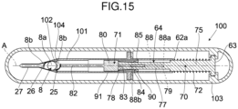
- An intraocular lens insertion device 100 shown in FIG.15 comprises a main body 101, an operation portion 63 and a knock system 64.
- An insertion tube portion 102 in which an intraocular lens 8 is placed in advance is attached to the main body 101.
- the intraocular lens insertion device 100 is a preload type intraocular lens insertion device fixed in a case 103 and packaged as well as shipped with the intraocular lens 8 placed thereinside. Instead of a rectangular receiving hole with which a cartridge is to be engaged, an attachment portion 104 for attaching the insertion tube portion 102 is provided on a distal end of the main body 101.
- the intraocular lens 8 is allowed to be released to the outside through two stages of operation just like the present embodiment. Further, the operation portion 63 is allowed to be automatically restored to an operation enabling position by means of the knock mechanism 64 at the time of operation.
- the intraocular lens insertion device 100 of the present embodiment comprises the knock system 64 for automatically restoring the operation portion 63 to the operation enabling position, such operation portion 63 being pushed to push out the intraocular lens 8.
- the knock system 64 for automatically restoring the operation portion 63 to the operation enabling position, such operation portion 63 being pushed to push out the intraocular lens 8.
- the intraocular lens insertion device 100 of the present embodiment is so packaged that it is actually fixed in the case 103, thus preventing the plunger 70 from being unintentionally pushed to the forward direction at the time of storing and shipping.
- the lens contact portion is left protruding from the nozzle section after releasing the intraocular lens to the outside.
- the present invention is not limited to such configuration.
- the lens contact portion may be configured to stay in the nozzle section, and the intraocular lens can be slowly released into the eye due to a shape recoverability thereof resulting from its elastic nature, even after the lens contact portion has stopped moving to the forward direction.
- the operation portion is allowed to move forward and backward in parallel with the lens advancement axis.
- the present invention is not limited to such configuration.
- the operation portion may be configured to move forward and backward in a direction orthogonal to the lens advancement axis.
- the operation portion is, for example, provided on a side surface of the main body, and the push-out point is located on an inner side direction (forward direction) of the main body, while the point of origin is located on an outer side direction (backward direction) thereof.
- the plunger serves as a transmitting portion.
- the present invention is not limited to such configuration.
- a link mechanism, a cam mechanism or the like can be employed as a transmitting portion by which the external force applied to the operation portion is transmitted to the lens contact portion.
- the insertion tube portion comprises the lens placement section.
- the present invention is not limited to such configuration.
- the insertion tube portion needs to comprise only the transition section and the nozzle section, and in such case, the lens placement section may be provided in the main body.
- the present invention can be applied to intraocular lens insertion devices of various embodiments such as those disclosed in Japanese Unexamined Patent Application Publication (Translation of PCT Application) No.2008-521535 , Japanese Unexamined Patent Application Publication (Translation of PCT Application) No.2001-502563 , Germany Patent No.4110278 , Japanese Unexamined Patent Application Publication No. Hei 4-212350 , and Japanese Unexamined Patent Application Publication No. Sho 63-197453 .
Landscapes
- Health & Medical Sciences (AREA)
- Ophthalmology & Optometry (AREA)
- Cardiology (AREA)
- Oral & Maxillofacial Surgery (AREA)
- Transplantation (AREA)
- Engineering & Computer Science (AREA)
- Biomedical Technology (AREA)
- Heart & Thoracic Surgery (AREA)
- Vascular Medicine (AREA)
- Life Sciences & Earth Sciences (AREA)
- Animal Behavior & Ethology (AREA)
- General Health & Medical Sciences (AREA)
- Public Health (AREA)
- Veterinary Medicine (AREA)
- Prostheses (AREA)
Claims (5)
- Vorrichtung zum Einsetzen einer intraokularen Linse, umfassend:einen Hauptkörper (2) mit einer sich durch ihn hindurch erstreckenden Linsenvorschubachse (A) und einem hinteren Ende (2a);einen Stab (7), der an seinem distalen Ende einen Linsenkontaktabschnitt (22) aufweist, der innerhalb des Hauptkörpers (2) in einer Vorwärtsrichtung entlang der Linsenvorschubachse (A) bewegbar ist, um eine intraokulare Linse zu schieben;einen Bedienungsabschnitt (5), der vom hinteren Ende (2a) des Hauptkörpers (2) entfernt ist;einen Stößel (6), der mit dem Stab (7) und dem Betätigungsabschnitt (5) verbunden ist und als Übertragungsabschnitt zum Übertragen einer auf den Betätigungsabschnitt (5) ausgeübten äußeren Kraft auf den Linsenkontaktabschnitt (22) zum Schieben der intraokularen Linse dient; undeinen Einführschlauch (4), der an einem vorderen Abschnitt des Hauptkörpers (2) befestigt ist und aus dem die Intraokularlinse nach außen freigegeben wird, nachdem sie durch den Linsenkontaktabschnitt (22) gedrückt wurde;dadurch gekennzeichnet, dassder Betätigungsabschnitt (5) einen ersten Betätigungsabschnitt (15) mit einer ersten Betätigungsfläche (15a) und einen zweiten Betätigungsabschnitt (16) umfasst, der mit dem ersten Betätigungsabschnitt (15) durch einen Abstandshalterabschnitt (17) derart verbunden ist, dass der zweite Betätigungsabschnitt (16) von dem ersten Betätigungsabschnitt (15) um einen vorgegebenen Abstand entlang der Linsenvorschubachse (A) getrennt ist; unddass die Intraokularlinsen-Einführvorrichtung ferner einen Rückhalteabschnitt (10) umfasst, der am hinteren Ende (2a) des Hauptkörpers (2) vorgesehen ist und als Anschlagmittel zum vorübergehenden Anhalten des Linsenkontaktabschnitts (22) dient, wenn die Intraokularlinse durch die Nähe eines distalen Endabschnitts des Einführungstubus (4) hindurchgeht, bevor die Intraokularlinse von dem Einführungstubus (4) freigegeben wird, wobeider Rückhalteabschnitt (10) eine Rückhaltefläche (31) umfasst, die orthogonal zur Linsenvorschubachse (A) ist und so konfiguriert ist, dass sie den Finger eines Bedieners, der den ersten Betätigungsabschnitt (15) in die Vorwärtsrichtung schiebt, an einer vorbestimmten Position zurückhält, an der die erste Betätigungsfläche (15a) mit der Rückhaltefläche (31) bündig ist.
- Intraokulare Linseneinsetzvorrichtung nach Anspruch 1, wobei
der Rückhalteabschnitt (10) so beschaffen ist, dass der zweite Betätigungsabschnitt (16) weiter in die Vorwärtsrichtung geschoben werden kann, sodass durch Drücken des zweiten Betätigungsabschnitts (16) der Linsenkontaktabschnitt (22) die Intraokularlinse von dem Einführtubus (4) löst. - Intraokulare Linseneinsetzvorrichtung nach Anspruch 1 oder Anspruch 2, wobei
die ersten und zweiten Betätigungsabschnitte (15, 16) zum schrittweisen Herausschieben der Intraokularlinse vorgesehen sind. - Intraokulare Linseneinsetzvorrichtung nach einem der Ansprüche 1 bis 3, wobei
der Rückhalteabschnitt (10) bewirkt, dass der Linsenkontaktabschnitt (22) vorübergehend an einer Stelle in einem Abstand von 10 mm von einem distalen Ende des Einführschlauchs (4) angehalten wird. - Intraokulare Linseneinsetzvorrichtung nach einem der Ansprüche 1 bis 3, wobei
der Rückhalteabschnitt (10) bewirkt, dass der Linsenkontaktabschnitt (22) vorübergehend angehalten wird, wenn die intraokulare Linse durch einen Düsenabschnitt (27) hindurchgeht, der am distalen Ende des Einführungsrohrs (4) vorgesehen ist.
Applications Claiming Priority (2)
| Application Number | Priority Date | Filing Date | Title |
|---|---|---|---|
| JP2008227641A JP5416379B2 (ja) | 2008-09-04 | 2008-09-04 | 眼内レンズ挿入器具 |
| PCT/JP2009/064976 WO2010026919A1 (ja) | 2008-09-04 | 2009-08-27 | 眼内レンズ挿入器具 |
Publications (3)
| Publication Number | Publication Date |
|---|---|
| EP2332501A1 EP2332501A1 (de) | 2011-06-15 |
| EP2332501A4 EP2332501A4 (de) | 2017-11-29 |
| EP2332501B1 true EP2332501B1 (de) | 2025-01-08 |
Family
ID=41797087
Family Applications (1)
| Application Number | Title | Priority Date | Filing Date |
|---|---|---|---|
| EP09811445.7A Active EP2332501B1 (de) | 2008-09-04 | 2009-08-27 | Instrument zum einsetzen von intraokularlinsen |
Country Status (4)
| Country | Link |
|---|---|
| US (1) | US8470032B2 (de) |
| EP (1) | EP2332501B1 (de) |
| JP (1) | JP5416379B2 (de) |
| WO (1) | WO2010026919A1 (de) |
Families Citing this family (49)
| Publication number | Priority date | Publication date | Assignee | Title |
|---|---|---|---|---|
| EP1832247B1 (de) | 2004-12-27 | 2015-06-24 | Hoya Corporation | Vorrichtung zur implantation einer intraokularlinse |
| US8545512B2 (en) | 2005-01-26 | 2013-10-01 | Hoya Corporation | Intraocular lens insertion device |
| JP4836046B2 (ja) | 2005-02-24 | 2011-12-14 | Hoya株式会社 | 眼内レンズ挿入器具 |
| WO2007037223A1 (ja) | 2005-09-28 | 2007-04-05 | Hoya Corporation | 眼内レンズ挿入用器具 |
| JP4877643B2 (ja) | 2005-12-08 | 2012-02-15 | Hoya株式会社 | 眼内レンズ挿入用器具 |
| JP5236637B2 (ja) | 2007-05-30 | 2013-07-17 | Hoya株式会社 | 眼内レンズ挿入器具及び眼内レンズ挿入装置 |
| WO2008149795A1 (ja) | 2007-05-30 | 2008-12-11 | Hoya Corporation | 眼内レンズ挿入器具 |
| JP5086713B2 (ja) | 2007-07-11 | 2012-11-28 | Hoya株式会社 | 眼内レンズ挿入器具 |
| JP5254669B2 (ja) | 2008-06-05 | 2013-08-07 | Hoya株式会社 | 眼内レンズ挿入器具及びカートリッジ |
| JP5470753B2 (ja) | 2008-06-17 | 2014-04-16 | Hoya株式会社 | 眼内レンズ挿入器具 |
| JP5323420B2 (ja) | 2008-08-21 | 2013-10-23 | Hoya株式会社 | 眼内レンズ挿入器具 |
| CN102307543B (zh) | 2009-01-07 | 2015-10-21 | Hoya株式会社 | 眼内透镜插入器具 |
| JP5570265B2 (ja) * | 2010-03-26 | 2014-08-13 | 株式会社ニデック | 眼内レンズ挿入器具 |
| JP5735531B2 (ja) | 2010-04-08 | 2015-06-17 | Hoya株式会社 | 眼内移植片挿入器具 |
| JP5511530B2 (ja) | 2010-06-10 | 2014-06-04 | Hoya株式会社 | 眼内レンズ挿入装置 |
| WO2012018006A1 (ja) * | 2010-08-03 | 2012-02-09 | Hoya株式会社 | 治療器具および付属器具 |
| WO2013021347A1 (en) * | 2011-08-11 | 2013-02-14 | Polymer Technologies International (Eou) | Intra-ocular lens injection cartridge |
| EP2806828B1 (de) | 2012-01-24 | 2021-07-21 | The Regents of The University of Colorado, A Body Corporate | Entwürfe und verfahren für modulare intraokularlinsen |
| US9314600B2 (en) * | 2012-04-15 | 2016-04-19 | Bioconnect Systems, Inc. | Delivery system for implantable flow connector |
| US9463089B2 (en) | 2012-05-21 | 2016-10-11 | Novartis Ag | Plunger system for intraocular lens surgery |
| CN104379092B (zh) | 2012-06-04 | 2016-12-14 | 爱尔康制药有限公司 | 眼内透镜插入器 |
| CA3078098C (en) | 2012-06-12 | 2022-03-15 | Alcon Inc. | Intraocular gas injector |
| AU2014226115B2 (en) * | 2013-03-05 | 2018-08-02 | Johnson & Johnson Surgical Vision, Inc. | Automated preloaded intraocular lens injector |
| US9504561B2 (en) * | 2013-03-07 | 2016-11-29 | Novartis Ag | Systems and processes for inserting an intraocular lens |
| AU2015219461B2 (en) | 2014-02-18 | 2019-10-31 | Alcon Inc. | Modular intraocular lens designs, tools and methods |
| CA2944513C (en) | 2014-04-04 | 2022-07-05 | Jack R. Auld | Intraocular lens inserter |
| EP3250152B1 (de) | 2015-01-30 | 2025-03-12 | Alcon Inc. | Inserter zum einführen einer basis und einer linse einer modularen intraokularlinse in ein auge |
| US10588780B2 (en) * | 2015-03-04 | 2020-03-17 | Alcon Inc. | Intraocular lens injector |
| JP6646987B2 (ja) | 2015-09-16 | 2020-02-14 | Hoya株式会社 | 眼内レンズ挿入器具 |
| AU2016324545A1 (en) | 2015-09-16 | 2018-04-12 | Hoya Corporation | Intraocular lens insertion tool |
| US10172706B2 (en) | 2015-10-31 | 2019-01-08 | Novartis Ag | Intraocular lens inserter |
| CN108348327B (zh) | 2015-11-04 | 2021-10-01 | 克拉维斯塔医疗有限公司 | 模块化人工晶状体设计、工具和方法 |
| WO2018003853A1 (ja) | 2016-06-28 | 2018-01-04 | Hoya株式会社 | 眼内レンズ挿入器 |
| US11033382B2 (en) | 2016-06-28 | 2021-06-15 | Hoya Corporation | Intraocular lens injector |
| US11000367B2 (en) | 2017-01-13 | 2021-05-11 | Alcon Inc. | Intraocular lens injector |
| US10568735B2 (en) | 2017-01-13 | 2020-02-25 | Alcon Inc. | Intraocular lens injector |
| US11382736B2 (en) | 2017-06-27 | 2022-07-12 | Alcon Inc. | Injector, intraocular lens system, and related methods |
| ES2962595T3 (es) | 2018-03-28 | 2024-03-20 | Bausch & Lomb Ireland Ltd | Ensamblaje de inyector que emplea gas comprimido y un freno mecánico para dispensar una lente intraocular a un paciente. |
| JP7162443B2 (ja) * | 2018-05-16 | 2022-10-28 | Hoya株式会社 | 容器付き眼内リング挿入器 |
| JP7162445B2 (ja) | 2018-05-25 | 2022-10-28 | Hoya株式会社 | 眼内レンズ挿入器 |
| US11224537B2 (en) | 2018-10-19 | 2022-01-18 | Alcon Inc. | Intraocular gas injector |
| US11324590B2 (en) * | 2018-12-19 | 2022-05-10 | Alcon Inc. | Collapsing push injector with hydraulic damping |
| US11096779B2 (en) * | 2018-12-19 | 2021-08-24 | Alcon Inc. | IOL injector having a spring-assisted IOL delivery mechanism |
| US11439500B2 (en) * | 2018-12-20 | 2022-09-13 | Alcon Inc. | IOL injector with automatic driver or assisted manual drive force |
| JP7327956B2 (ja) | 2019-03-13 | 2023-08-16 | Hoya株式会社 | 眼内レンズ挿入器具 |
| KR102391641B1 (ko) * | 2019-05-10 | 2022-04-29 | 정영택 | 관류액이 공급되는 안과 수술용 인공수정체 삽입 기구 |
| DE102021116615B3 (de) * | 2021-06-28 | 2022-07-14 | Carl Zeiss Meditec Ag | Injektor mit einem ersten Kolben und einem zweiten Kolben |
| JP2023051283A (ja) * | 2021-09-30 | 2023-04-11 | Hoya株式会社 | 眼内レンズ挿入器具 |
| KR102469016B1 (ko) * | 2022-01-24 | 2022-11-22 | 재영솔루텍 주식회사 | 안구내 캡슐러 텐션링 삽입기구 |
Family Cites Families (186)
| Publication number | Priority date | Publication date | Assignee | Title |
|---|---|---|---|---|
| US2761446A (en) | 1955-03-30 | 1956-09-04 | Chemical Specialties Co Inc | Implanter and cartridge |
| US4205747A (en) | 1978-09-05 | 1980-06-03 | Cilco, Inc. | Lens storage device |
| US4269307A (en) | 1979-08-09 | 1981-05-26 | Iolab Corporation | Intraocular lens storage assembly |
| US4573998A (en) | 1982-02-05 | 1986-03-04 | Staar Surgical Co. | Methods for implantation of deformable intraocular lenses |
| US4423809A (en) | 1982-02-05 | 1984-01-03 | Staar Surgical Company, Inc. | Packaging system for intraocular lens structures |
| US4702244A (en) | 1982-02-05 | 1987-10-27 | Staar Surgical Company | Surgical device for implantation of a deformable intraocular lens |
| US4608049A (en) | 1982-06-28 | 1986-08-26 | Kelman Charles D | Intraocular lens and method of inserting an intraocular lens into an eye |
| US4634423A (en) | 1984-04-30 | 1987-01-06 | Bailey Jr Paul F | Ophthalmological method and instrument for implantation of posterior chamber intraocular lens |
| US4787904A (en) | 1984-07-06 | 1988-11-29 | Severin Sanford L | Hydrophillic intraocular lens |
| US4699140A (en) | 1985-07-10 | 1987-10-13 | Iolab Corporation | Instrument for inserting an intraocular lens |
| US4681102A (en) | 1985-09-11 | 1987-07-21 | Bartell Michael T | Apparatus and method for insertion of an intra-ocular lens |
| US4715373A (en) * | 1985-09-27 | 1987-12-29 | Mazzocco Thomas R | Devices for implantation of deformable intraocular lens structures |
| US4750498A (en) | 1986-02-21 | 1988-06-14 | Coopervision, Inc. | Method and tool for inserting an intraocular lens |
| DE3610925C2 (de) | 1986-03-24 | 1994-11-03 | Michael Ulrich Prof D Dardenne | Vorrichtung zum Falten einer insbesondere mit zwei seitlichen Kunststoffhaptikplatten versehenen, implantierbaren Intraokularlinse und zum Einbringen der gefalteten Intraokularlinse in das Auge |
| US4697697A (en) | 1986-08-18 | 1987-10-06 | Coopervision, Inc. | Method and apparatus for packaging an intraocular lens |
| US4919130A (en) | 1986-11-07 | 1990-04-24 | Nestle S.A. | Tool for inserting compressible intraocular lenses into the eye and method |
| JPS63197453A (ja) | 1986-11-07 | 1988-08-16 | ザ・クーパー・カンパニー・インク | 圧縮性眼内レンズを眼に挿入する器具および方法 |
| US4747404A (en) | 1986-11-10 | 1988-05-31 | Kresge Eye Institute Of Wayne State University | Foldable intraocular lens inserter |
| US4763650A (en) | 1987-01-20 | 1988-08-16 | Hauser Stephen G | Instrument for inserting a deformable lens into the eye |
| US4994028A (en) | 1987-03-18 | 1991-02-19 | Endocon, Inc. | Injector for inplanting multiple pellet medicaments |
| US4819631A (en) | 1987-03-26 | 1989-04-11 | Poley Brooks J | Folded intraocular lens, method of implanting it, retainer, and apparatus for folding lens |
| US4769034A (en) | 1987-03-26 | 1988-09-06 | Poley Brooks J | Folded intraocular lens, method of implanting folded intraocular lens |
| US5176686A (en) | 1987-03-26 | 1993-01-05 | Poley Brooks J | Apparatus for packaging, folding, rigidifying and inserting an intraocular lens |
| US4988352A (en) | 1987-03-26 | 1991-01-29 | Poley Brooks J | Method and apparatus for folding, freezing and implanting intraocular lens |
| US4781719A (en) | 1987-07-28 | 1988-11-01 | Kelman Charles D | Method of inserting an intraocular lens into an eye |
| US4759359A (en) | 1987-08-31 | 1988-07-26 | Allergan, Inc. | Lens implantation instrument |
| US4834094A (en) | 1987-10-07 | 1989-05-30 | Patton Medical Technologies, Inc. | "Canoe" apparatus for inserting intra-ocular lens into the eye |
| US4765329A (en) | 1987-10-19 | 1988-08-23 | Cumming, Redwitz & Wilson, Inc. | Intraocular lens insertion instrument |
| US4934363A (en) | 1987-12-15 | 1990-06-19 | Iolab Corporation | Lens insertion instrument |
| US4880000A (en) | 1987-12-15 | 1989-11-14 | Iolab Corporation | Lens insertion instrument |
| US4836201A (en) | 1988-03-24 | 1989-06-06 | Patton Medical Technologies, Inc. | "Envelope" apparatus for inserting intra-ocular lens into the eye |
| US4862885A (en) | 1988-05-25 | 1989-09-05 | Cumming J Stuart | Instrument for inserting a deformable intraocular lens into the eye |
| AU623934B2 (en) | 1988-10-07 | 1992-05-28 | Ioptex Research Inc | Intraocular lens insertion instrument |
| US4976716A (en) | 1989-01-23 | 1990-12-11 | Cumming J Stuart | Intraocular lens insertion device |
| US5066297A (en) | 1989-01-23 | 1991-11-19 | Cumming J Stuart | Intraocular lens insertion device |
| US4955889A (en) | 1989-02-06 | 1990-09-11 | Allergan, Inc. | Apparatus for inserting a lens into an eye and method for using same |
| US5222972A (en) | 1989-04-12 | 1993-06-29 | Allergan, Inc. | Small incision intraocular lens insertion apparatus |
| US5098439A (en) | 1989-04-12 | 1992-03-24 | Allergan, Inc. | Small incision intraocular lens insertion apparatus |
| US5171241A (en) | 1989-06-09 | 1992-12-15 | Ioptex Research Inc. | Device for folding an intraocular lens and holding it in the folded state |
| DE4030492C1 (de) | 1990-09-26 | 1991-09-05 | Adatomed Pharmazeutische Und Medizintechnische Gesellschaft Mbh, 8000 Muenchen, De | |
| DE4039119C1 (de) | 1990-12-07 | 1991-09-05 | Dieter Dr.Med. 8904 Friedberg De Klaas | |
| DE4108303C2 (de) | 1991-03-14 | 1993-11-04 | Adatomed Pharma & Med | Verfahren und vorrichtung zum einbringen einer gummielastischen intraokularlinse in ein implantationswerkzeug |
| DE4110278A1 (de) | 1991-03-28 | 1992-10-01 | Geuder Hans Gmbh | Augenchirurgisches instrument zum implantieren von hinterkammer-weichlinsen |
| US5123905A (en) | 1991-06-07 | 1992-06-23 | Kelman Charles D | Intraocular lens injector |
| US5178622A (en) * | 1991-11-01 | 1993-01-12 | Lehner Ii Robert H | Instrument for implanting a soft intraocular lens |
| US5190552A (en) * | 1992-02-04 | 1993-03-02 | Kelman Charles D | Slotted tube injector for an intraocular lens |
| US5571113A (en) | 1992-05-18 | 1996-11-05 | Henry H. McDonald | Surgical probe with tips for plastic lens implantation in the eye |
| US5395378A (en) | 1992-05-18 | 1995-03-07 | Henry H. McDonald | Eye implantable lens haptics insertion and twist apparatus |
| US5242450A (en) | 1992-05-18 | 1993-09-07 | Henry H. McDonald | Eye implantable lens haptics twist apparatus |
| US5304182A (en) | 1992-09-23 | 1994-04-19 | Kabi Pharmacia Ophthalmics, Inc. | Apparatus and method for curling and inserting flexible intraocular lenses |
| US6022358A (en) | 1992-09-30 | 2000-02-08 | Staar Surgical Company, Inc. | Deformable intraocular lens injecting device |
| US6059791A (en) | 1992-09-30 | 2000-05-09 | Staar Surgical Company, Inc. | Deformable intraocular lens injection system, and method thereof |
| US5499987A (en) | 1992-09-30 | 1996-03-19 | Staar Surgical Company | Deformable intraocular lens cartridge |
| US6712848B1 (en) | 1992-09-30 | 2004-03-30 | Staar Surgical Company, Inc. | Deformable intraocular lens injecting apparatus with transverse hinged lens cartridge |
| US5860984A (en) | 1992-09-30 | 1999-01-19 | Staar Surgical Company, Inc. | Spring biased deformable intraocular injecting apparatus |
| PT723429E (pt) | 1992-09-30 | 2002-09-30 | Vladimir Feingold | Sistema de insercao de lentes intra-oculares |
| US6506195B2 (en) | 1992-09-30 | 2003-01-14 | Staar Surgical Company, Inc. | Deformable intraocular lens insertion system |
| US5728102A (en) | 1992-09-30 | 1998-03-17 | Staar Surgical Company, Inc. | Disposable intraocular lens insertion system |
| US6001107A (en) | 1992-09-30 | 1999-12-14 | Staar Surgical Company, Inc. | Deformable intraocular lens injecting apparatus |
| US5876440A (en) | 1992-09-30 | 1999-03-02 | Staar Surgical Company, Inc. | Methods of implantation of deformable intraocular lens |
| US5616148A (en) | 1992-09-30 | 1997-04-01 | Staar Surgical Company, Inc. | Transverse hinged deformable intraocular lens injecting apparatus |
| US6406481B2 (en) | 1992-09-30 | 2002-06-18 | Starr Surgical Company, Inc. | Method preloading a deformable intraocular lens into injecting apparatus for storage and/or shipment |
| US6056757A (en) | 1992-09-30 | 2000-05-02 | Staar Surgical Company, Inc. | Implantation device with deformable nozzle tip for implanting a deformable intraocular lens |
| US5620450A (en) | 1992-09-30 | 1997-04-15 | Staar Surgical Company, Inc. | Transverse hinged deformable intraocular lens injecting apparatus |
| US5928245A (en) | 1992-09-30 | 1999-07-27 | Staar Surgical Company, Inc. | Deformable intraocular lens injecting apparatus with transverse hinged lens cartridge |
| US5772666A (en) | 1992-09-30 | 1998-06-30 | Staar Surgical Company, Inc. | Deformable intraocular lens injecting apparatus with deformable tip plunger |
| US5941886A (en) | 1992-09-30 | 1999-08-24 | Staar Surgical Company, Inc. | Hingeless lens cartridges for insertion of deformable intraocular lens |
| US5807400A (en) | 1992-09-30 | 1998-09-15 | Staar Surgical Company, Inc. | Deformable intraocular lens insertion system |
| US5281227A (en) | 1992-11-09 | 1994-01-25 | Allergan, Inc. | Lens case with IOL folding device |
| US5275604A (en) | 1992-12-03 | 1994-01-04 | Kabi Pharmacia Ophthalmics, Inc. | Contoured duct apparatus and method for insertion of flexible intraocular lens |
| US5653715A (en) | 1993-03-09 | 1997-08-05 | Chiron Vision Corporation | Apparatus for preparing an intraocular lens for insertion |
| US5468246A (en) | 1993-07-02 | 1995-11-21 | Iovision, Inc. | Intraocular lens injector |
| US5425734A (en) | 1993-07-02 | 1995-06-20 | Iovision, Inc. | Intraocular lens injector |
| JP3459664B2 (ja) | 1993-07-15 | 2003-10-20 | キヤノンスター株式会社 | 変形可能な眼内レンズの挿入器具 |
| US5702402A (en) | 1994-04-29 | 1997-12-30 | Allergal | Method and apparatus for folding of intraocular lens |
| US5582613A (en) | 1993-11-18 | 1996-12-10 | Allergan | Apparatus and methods for controlled insertion of intraocular lenses |
| US5584304A (en) | 1993-11-18 | 1996-12-17 | Allergan, Inc. | Method of inserting an IOL using a forceps inside a folding tube |
| WO1995013766A1 (en) | 1993-11-18 | 1995-05-26 | Allergan, Inc. | Deformable lens insertion apparatus |
| AU1915595A (en) | 1994-02-09 | 1995-08-29 | Kabi Pharmacia Ophthalmics, Inc. | Rapid implantation of shape transformable optical lenses |
| US6174315B1 (en) | 1994-02-15 | 2001-01-16 | Staar Surgical Company, Inc. | Spring biased deformable intraocular injecting apparatus |
| US5578042A (en) | 1994-03-14 | 1996-11-26 | Cumming; J. Stuart | Ophthalmic kit and method for lens insertion |
| JP3412106B2 (ja) | 1994-07-07 | 2003-06-03 | キヤノンスター株式会社 | 変形可能な眼内レンズの挿入器具 |
| US5454818A (en) | 1994-07-26 | 1995-10-03 | Alcon Laboratories, Inc. | Intraocular lens folder |
| EP1338254B1 (de) | 1994-08-05 | 2008-12-03 | Bausch & Lomb Incorporated | Verfahren zum Verpacken einer Intraokularlinse |
| ATE245012T1 (de) | 1994-11-18 | 2003-08-15 | Vladimir Feingold | Einführungssystem für wegwerfbare intraokulare linsen |
| US5803925A (en) | 1995-01-17 | 1998-09-08 | Allergan | IOL insertion apparatus with covalently bonded lubricant |
| CN1185100A (zh) | 1995-03-14 | 1998-06-17 | 约翰·R·沃尔夫 | 柔性眼内晶状体注射系统 |
| CN1185098A (zh) | 1995-05-24 | 1998-06-17 | 托马斯·J·钱伯斯 | 柔性眼内晶状体注射系统和注射方法 |
| US5643276A (en) | 1995-10-10 | 1997-07-01 | Allergan | Apparatus and method for providing desired rotational orientation to an intraocular lens |
| US5776138A (en) | 1996-01-26 | 1998-07-07 | Allergan | Apparatus and methods for IOL insertion |
| US5735858A (en) | 1996-01-26 | 1998-04-07 | Allergan | IOL insertion apparatus and method for using same |
| US6083230A (en) | 1997-07-30 | 2000-07-04 | Allergan | Method for making IOL insertion apparatus |
| US5716364A (en) | 1996-07-10 | 1998-02-10 | Allergan | IOL insertion apparatus and method for making and using same |
| US6283975B1 (en) | 1996-07-10 | 2001-09-04 | Allergan Sales, Inc. | IOL insertion apparatus and method for making and using same |
| US5876406A (en) | 1996-08-02 | 1999-03-02 | Staar Surgical Company, Inc. | Deformable intraocular lens injecting apparatus with transverse hinged lens cartridge |
| US5766181A (en) | 1996-08-02 | 1998-06-16 | Staar Surgical Company, Inc. | Spring biased deformable intraocular injecting apparatus |
| US5944725A (en) | 1996-09-26 | 1999-08-31 | Bausch & Lomb Surgical, Inc. | Method and apparatus for inserting a flexible membrane into an eye |
| US5810834A (en) | 1996-10-07 | 1998-09-22 | Chiron Vision Corporation | Tip formation for inserting a flexible membrane into an eye |
| JP3226813B2 (ja) | 1996-12-13 | 2001-11-05 | トリンプ・インターナショナル・ジャパン株式会社 | 女性用衣類 |
| US5947975A (en) | 1997-03-07 | 1999-09-07 | Canon Staar Co., Inc. | Inserting device for deformable intraocular lens |
| US5919197A (en) | 1997-05-05 | 1999-07-06 | Surgical Concepts, Inc. | Insertion of multiple folded lens into the eye |
| US5947974A (en) | 1997-12-09 | 1999-09-07 | Allergan | Folding device and method for an intraocular lens |
| US5921989A (en) | 1998-02-12 | 1999-07-13 | Allergan | Lens protector for intraocular lens inserter |
| US6371960B2 (en) | 1998-05-19 | 2002-04-16 | Bausch & Lomb Surgical, Inc. | Device for inserting a flexible intraocular lens |
| US6010510A (en) | 1998-06-02 | 2000-01-04 | Alcon Laboratories, Inc. | Plunger |
| US6143001A (en) | 1998-06-02 | 2000-11-07 | Alcon Laboratories, Inc. | Asymmetric intraocular lens injection cartridge |
| US6447520B1 (en) | 2001-03-19 | 2002-09-10 | Advanced Medical Optics, Inc. | IOL insertion apparatus with IOL engagement structure and method for using same |
| DE19904220C2 (de) | 1999-02-03 | 2001-08-30 | Helmut Binder | Injektor zum Falten und Einbringen einer Intraokularlinse, und Behälter zum Lagern und Transportieren des Injektors |
| US6129733A (en) | 1999-04-15 | 2000-10-10 | Allergan Sales, Inc. | Apparatus for holding intraocular lenses and injectors, and methods for using same |
| US6386357B1 (en) | 1999-07-12 | 2002-05-14 | Hoya Healthcare Corporation | Soft intraocular lens-folding device and storage case |
| US6248111B1 (en) | 1999-08-06 | 2001-06-19 | Allergan Sales, Inc. | IOL insertion apparatus and methods for using same |
| JP3728155B2 (ja) | 1999-10-05 | 2005-12-21 | キヤノンスター株式会社 | 眼内挿入用レンズの挿入システム |
| JP3944555B2 (ja) | 1999-10-06 | 2007-07-11 | キヤノンスター株式会社 | 眼内挿入用レンズの挿入システム |
| US6387101B1 (en) | 1999-10-22 | 2002-05-14 | Staar Surgical Company, Inc. | Deformable intraocular lens injecting apparatus and method |
| US6312433B1 (en) | 1999-10-22 | 2001-11-06 | Staar Surgical Company, Inc. | Deformable intraocular lens injecting apparatus and method |
| US6251114B1 (en) | 1999-10-29 | 2001-06-26 | Allergan Sales, Inc. | Rotatable IOL insertion apparatus and method for using same |
| SE9904338D0 (sv) | 1999-11-30 | 1999-11-30 | Pharmacia & Upjohn Ab | Intraocular lens implanter |
| US6283976B1 (en) | 2000-05-05 | 2001-09-04 | Allergan Sales Inc. | Intraocular lens implanting instrument |
| GB0011507D0 (en) | 2000-05-13 | 2000-06-28 | Duckworth & Kent Ltd | Ophthalmic lens injectors |
| FR2814360B1 (fr) | 2000-09-28 | 2002-12-27 | Corneal Ind | Injecteur d'implant intraoculaire souple |
| US6500181B1 (en) | 2000-10-17 | 2002-12-31 | Valdemar Portney | Instrument for folding and inserting anterior chamber intraocular lenses |
| US6471708B2 (en) | 2000-12-21 | 2002-10-29 | Bausch & Lomb Incorporated | Intraocular lens and additive packaging system |
| US6554839B2 (en) | 2001-01-26 | 2003-04-29 | Advanced Medical Optics, Inc. | Stepped IOL insertion cartridge for inserting an intraocular lens in an eye |
| US6540754B2 (en) | 2001-01-26 | 2003-04-01 | Advanced Medical Optics, Inc. | Apparatus and method for multiply folding and inserting an intraocular lens in an eye |
| FR2822055B1 (fr) | 2001-03-16 | 2003-09-12 | Lab Contactologie Appl Lca | Injecteur pour lentille intraoculaire |
| US6786911B2 (en) | 2001-05-25 | 2004-09-07 | Hoya Healthcare Corporation | Storage case having soft intraocular lens folding function |
| JP2002355268A (ja) | 2001-06-01 | 2002-12-10 | Nidek Co Ltd | 眼内レンズ挿入器具 |
| US6537283B2 (en) | 2001-08-17 | 2003-03-25 | Alcon, Inc. | Intraocular lens shipping case and injection cartridge |
| EP1287791B1 (de) | 2001-08-23 | 2009-09-09 | Anton Meyer & Co. AG | Vorrichtung zur Einführung einer Linse in ein Auge |
| JP3861138B2 (ja) | 2001-09-04 | 2006-12-20 | キヤノンスター株式会社 | 眼内レンズの挿入器具 |
| US7037312B2 (en) | 2001-09-07 | 2006-05-02 | Canon-Staar Co., Inc. | Insertion device for deformable intraocular lens |
| FR2833154B1 (fr) | 2001-12-12 | 2004-11-19 | Ioltechnologie Production | Cassette et injecteur de lentille intraoculaire souple et procede d'injection de telles lentilles |
| JP3791421B2 (ja) | 2002-01-23 | 2006-06-28 | キヤノンスター株式会社 | 眼内レンズの挿入器具 |
| US6723104B2 (en) | 2002-03-13 | 2004-04-20 | Advanced Medical Optics, Inc. | IOL insertion apparatus and method for using same |
| US6733507B2 (en) | 2002-04-12 | 2004-05-11 | Advanced Medical Optics, Inc. | Intraocular lens insertion apparatus |
| JP3876284B2 (ja) | 2002-05-08 | 2007-01-31 | キヤノンスター株式会社 | 眼内挿入用レンズの挿入器具 |
| US7014641B2 (en) | 2002-05-08 | 2006-03-21 | Canon-Staar Co., Inc. | Insertion device for intraocular lens |
| JP2003325569A (ja) | 2002-05-08 | 2003-11-18 | Canon Star Kk | 眼内挿入用レンズの挿入システム |
| JP2003325572A (ja) | 2002-05-08 | 2003-11-18 | Canon Star Kk | 眼内挿入用レンズの挿入システム |
| JP2003325570A (ja) | 2002-05-08 | 2003-11-18 | Canon Star Kk | 眼内挿入用レンズの挿入システム |
| US7131976B2 (en) | 2002-05-08 | 2006-11-07 | Canon-Staar Co. Inc. | Insertion device for intraocular lens |
| US6923815B2 (en) | 2002-05-14 | 2005-08-02 | Advanced Medical Optics, Inc. | Intraocular lens insertion apparatus |
| AU2003246350B2 (en) | 2002-07-26 | 2009-12-10 | Amo Groningen B.V. | Method and device for manipulation of an intraocular lens |
| ES2305194T3 (es) | 2002-12-09 | 2008-11-01 | ANTON MEYER & CO. AG | Aguaj de embolo para un inyector de lentes intraocular. |
| US7074227B2 (en) | 2002-12-12 | 2006-07-11 | Valdemar Portney | IOL insertion tool with forceps |
| US20060293694A1 (en) | 2003-05-27 | 2006-12-28 | Hoya Corporation | Injector |
| US7156854B2 (en) * | 2003-05-28 | 2007-01-02 | Alcon, Inc. | Lens delivery system |
| US8403941B2 (en) | 2003-06-02 | 2013-03-26 | Abbott Medical Optics Inc. | Intraocular lens and cartridge packaging with lens-loading function |
| US7422604B2 (en) | 2003-08-28 | 2008-09-09 | Bausch & Lomb Incorporated | Preloaded IOL injector |
| US7429263B2 (en) | 2003-08-28 | 2008-09-30 | Bausch & Lomb Incorporated | Preloaded IOL injector |
| JP4590505B2 (ja) | 2003-10-01 | 2010-12-01 | スター・ジャパン株式会社 | 眼内レンズの挿入器具 |
| WO2005070341A1 (ja) | 2004-01-27 | 2005-08-04 | Hoya Corporation | 眼内レンズ挿入装置及びそのカートリッジ |
| US7645300B2 (en) | 2004-02-02 | 2010-01-12 | Visiogen, Inc. | Injector for intraocular lens system |
| WO2005084588A1 (en) | 2004-03-02 | 2005-09-15 | Advanced Medical Optics | Devices and methods for storing, loading, and delivering an intraocular lens |
| US7458976B2 (en) | 2005-03-02 | 2008-12-02 | Advanced Medical Optics, Inc. | Devices and methods for storing, loading, and delivering an intraocular lens |
| US7947049B2 (en) | 2004-03-31 | 2011-05-24 | Bausch & Lomb Incorporated | IOL injector |
| DE502004011274D1 (de) * | 2004-04-22 | 2010-07-22 | Advanced Vision Science Inc | Vorrichtung zum einsetzen verformbarer intraocularlinsen |
| US20060085013A1 (en) * | 2004-10-20 | 2006-04-20 | Vaclav Dusek | Intraocular lens inserter |
| AU2004325365B2 (en) | 2004-11-30 | 2011-02-10 | Bausch & Lomb Incorporated | Two stage plunger for intraocular lens injector |
| EP1832247B1 (de) | 2004-12-27 | 2015-06-24 | Hoya Corporation | Vorrichtung zur implantation einer intraokularlinse |
| JP4766442B2 (ja) | 2004-12-28 | 2011-09-07 | Hoya株式会社 | 眼内レンズ挿入用器具 |
| US20060167466A1 (en) | 2005-01-21 | 2006-07-27 | Vaclav Dusek | Intraocular lens inserter system components |
| US8545512B2 (en) | 2005-01-26 | 2013-10-01 | Hoya Corporation | Intraocular lens insertion device |
| US8435289B2 (en) | 2005-02-11 | 2013-05-07 | Abbott Medical Optics Inc. | Rapid exchange IOL insertion apparatus and methods of using |
| JP4836046B2 (ja) | 2005-02-24 | 2011-12-14 | Hoya株式会社 | 眼内レンズ挿入器具 |
| JP4481878B2 (ja) | 2005-05-31 | 2010-06-16 | 株式会社ニデック | 眼内レンズ挿入器具 |
| JP2006333981A (ja) | 2005-05-31 | 2006-12-14 | Canon Star Kk | 眼内挿入用レンズの挿入器具 |
| WO2007037223A1 (ja) * | 2005-09-28 | 2007-04-05 | Hoya Corporation | 眼内レンズ挿入用器具 |
| JP4877643B2 (ja) | 2005-12-08 | 2012-02-15 | Hoya株式会社 | 眼内レンズ挿入用器具 |
| JP5041322B2 (ja) | 2006-01-10 | 2012-10-03 | Hoya株式会社 | 眼内レンズ挿入器具 |
| EP1972306A4 (de) | 2006-01-13 | 2012-11-28 | Hoya Corp | Instrument zum einsetzen von intraokularlinsen |
| WO2007087641A2 (en) | 2006-01-26 | 2007-08-02 | Advanced Medical Optics, Inc. | Intraocular lens insertion apparatus and lens case |
| JP4947484B2 (ja) | 2006-02-22 | 2012-06-06 | Hoya株式会社 | 眼内レンズ挿入器具 |
| JP5103809B2 (ja) | 2006-06-30 | 2012-12-19 | ぺんてる株式会社 | ボールペン用油性インキ |
| JP5103808B2 (ja) | 2006-06-30 | 2012-12-19 | 凸版印刷株式会社 | 積層体 |
| US20080221584A1 (en) * | 2007-03-06 | 2008-09-11 | Downer David A | Lens Delivery System |
| JP5236637B2 (ja) | 2007-05-30 | 2013-07-17 | Hoya株式会社 | 眼内レンズ挿入器具及び眼内レンズ挿入装置 |
| WO2008149795A1 (ja) | 2007-05-30 | 2008-12-11 | Hoya Corporation | 眼内レンズ挿入器具 |
| JP5086713B2 (ja) | 2007-07-11 | 2012-11-28 | Hoya株式会社 | 眼内レンズ挿入器具 |
| US8105332B2 (en) | 2007-10-30 | 2012-01-31 | Novartis Ag | Lens delivery system |
| JP5254669B2 (ja) | 2008-06-05 | 2013-08-07 | Hoya株式会社 | 眼内レンズ挿入器具及びカートリッジ |
| JP5470753B2 (ja) | 2008-06-17 | 2014-04-16 | Hoya株式会社 | 眼内レンズ挿入器具 |
| JP5323420B2 (ja) | 2008-08-21 | 2013-10-23 | Hoya株式会社 | 眼内レンズ挿入器具 |
| CN102307543B (zh) | 2009-01-07 | 2015-10-21 | Hoya株式会社 | 眼内透镜插入器具 |
| JP5735531B2 (ja) | 2010-04-08 | 2015-06-17 | Hoya株式会社 | 眼内移植片挿入器具 |
| JP5511530B2 (ja) | 2010-06-10 | 2014-06-04 | Hoya株式会社 | 眼内レンズ挿入装置 |
-
2008
- 2008-09-04 JP JP2008227641A patent/JP5416379B2/ja active Active
-
2009
- 2009-08-27 US US13/061,143 patent/US8470032B2/en active Active
- 2009-08-27 EP EP09811445.7A patent/EP2332501B1/de active Active
- 2009-08-27 WO PCT/JP2009/064976 patent/WO2010026919A1/ja not_active Ceased
Also Published As
| Publication number | Publication date |
|---|---|
| US20110264101A1 (en) | 2011-10-27 |
| EP2332501A1 (de) | 2011-06-15 |
| JP5416379B2 (ja) | 2014-02-12 |
| WO2010026919A1 (ja) | 2010-03-11 |
| EP2332501A4 (de) | 2017-11-29 |
| JP2010057767A (ja) | 2010-03-18 |
| US8470032B2 (en) | 2013-06-25 |
Similar Documents
| Publication | Publication Date | Title |
|---|---|---|
| EP2332501B1 (de) | Instrument zum einsetzen von intraokularlinsen | |
| EP2340786B1 (de) | Instrument zur einführung einer intraokularlinse | |
| US8273122B2 (en) | Pre-loaded IOL insertion system | |
| JP6379421B2 (ja) | 眼内レンズ用インジェクタ | |
| US8574239B2 (en) | Intraocular lens insertion device | |
| EP0813400B1 (de) | Deformierbares intraokulares linsen insertions-system | |
| EP1961399B1 (de) | Instrument zum einführen einer intraokularlinse | |
| US10105258B2 (en) | Device for receiving an intraocular lens, and method for folding an intraocular lens | |
| WO2009154187A1 (ja) | 眼内レンズ挿入器具 | |
| US20060085013A1 (en) | Intraocular lens inserter | |
| EP1891911A1 (de) | Linseneinführsystem | |
| KR102431214B1 (ko) | 안내 렌즈 삽입기 | |
| MX2008003114A (es) | Sistema de entrega de lente. | |
| CN108024854A (zh) | 眼植入物容器 | |
| EP3372197A1 (de) | Intraokularlinseninjektor und verfahren zum betreiben eines intraokularlinseninjektors | |
| CN113194879B (zh) | Iol折叠装置 | |
| CN112469366B (zh) | 用于人工晶状体注入器的侧推按钮 | |
| EP3989879B1 (de) | Iol-basiskompressionsvorrichtung mit einem iol-schleppmechanismus |
Legal Events
| Date | Code | Title | Description |
|---|---|---|---|
| PUAI | Public reference made under article 153(3) epc to a published international application that has entered the european phase |
Free format text: ORIGINAL CODE: 0009012 |
|
| 17P | Request for examination filed |
Effective date: 20110404 |
|
| AK | Designated contracting states |
Kind code of ref document: A1 Designated state(s): AT BE BG CH CY CZ DE DK EE ES FI FR GB GR HR HU IE IS IT LI LT LU LV MC MK MT NL NO PL PT RO SE SI SK SM TR |
|
| AX | Request for extension of the european patent |
Extension state: AL BA RS |
|
| DAX | Request for extension of the european patent (deleted) | ||
| RA4 | Supplementary search report drawn up and despatched (corrected) |
Effective date: 20171027 |
|
| RIC1 | Information provided on ipc code assigned before grant |
Ipc: A61F 2/16 20060101AFI20171023BHEP |
|
| STAA | Information on the status of an ep patent application or granted ep patent |
Free format text: STATUS: EXAMINATION IS IN PROGRESS |
|
| 17Q | First examination report despatched |
Effective date: 20200317 |
|
| RAP1 | Party data changed (applicant data changed or rights of an application transferred) |
Owner name: HOYA CORPORATION |
|
| GRAP | Despatch of communication of intention to grant a patent |
Free format text: ORIGINAL CODE: EPIDOSNIGR1 |
|
| STAA | Information on the status of an ep patent application or granted ep patent |
Free format text: STATUS: GRANT OF PATENT IS INTENDED |
|
| INTG | Intention to grant announced |
Effective date: 20240801 |
|
| RAP3 | Party data changed (applicant data changed or rights of an application transferred) |
Owner name: HOYA CORPORATION |
|
| GRAS | Grant fee paid |
Free format text: ORIGINAL CODE: EPIDOSNIGR3 |
|
| GRAA | (expected) grant |
Free format text: ORIGINAL CODE: 0009210 |
|
| STAA | Information on the status of an ep patent application or granted ep patent |
Free format text: STATUS: THE PATENT HAS BEEN GRANTED |
|
| AK | Designated contracting states |
Kind code of ref document: B1 Designated state(s): AT BE BG CH CY CZ DE DK EE ES FI FR GB GR HR HU IE IS IT LI LT LU LV MC MK MT NL NO PL PT RO SE SI SK SM TR |
|
| REG | Reference to a national code |
Ref country code: GB Ref legal event code: FG4D |
|
| REG | Reference to a national code |
Ref country code: CH Ref legal event code: EP |
|
| P01 | Opt-out of the competence of the unified patent court (upc) registered |
Free format text: CASE NUMBER: APP_65583/2024 Effective date: 20241212 |
|
| REG | Reference to a national code |
Ref country code: DE Ref legal event code: R096 Ref document number: 602009065437 Country of ref document: DE |
|
| REG | Reference to a national code |
Ref country code: IE Ref legal event code: FG4D |
|
| RAP2 | Party data changed (patent owner data changed or rights of a patent transferred) |
Owner name: HOYA MEDICAL SINGAPORE PTE. LTD. |
|
| REG | Reference to a national code |
Ref country code: LT Ref legal event code: MG9D |
|
| REG | Reference to a national code |
Ref country code: AT Ref legal event code: MK05 Ref document number: 1757849 Country of ref document: AT Kind code of ref document: T Effective date: 20250108 |
|
| PG25 | Lapsed in a contracting state [announced via postgrant information from national office to epo] |
Ref country code: NL Free format text: LAPSE BECAUSE OF FAILURE TO SUBMIT A TRANSLATION OF THE DESCRIPTION OR TO PAY THE FEE WITHIN THE PRESCRIBED TIME-LIMIT Effective date: 20250108 |
|
| PG25 | Lapsed in a contracting state [announced via postgrant information from national office to epo] |
Ref country code: FI Free format text: LAPSE BECAUSE OF FAILURE TO SUBMIT A TRANSLATION OF THE DESCRIPTION OR TO PAY THE FEE WITHIN THE PRESCRIBED TIME-LIMIT Effective date: 20250108 |
|
| PG25 | Lapsed in a contracting state [announced via postgrant information from national office to epo] |
Ref country code: PL Free format text: LAPSE BECAUSE OF FAILURE TO SUBMIT A TRANSLATION OF THE DESCRIPTION OR TO PAY THE FEE WITHIN THE PRESCRIBED TIME-LIMIT Effective date: 20250108 |
|
| PG25 | Lapsed in a contracting state [announced via postgrant information from national office to epo] |
Ref country code: ES Free format text: LAPSE BECAUSE OF FAILURE TO SUBMIT A TRANSLATION OF THE DESCRIPTION OR TO PAY THE FEE WITHIN THE PRESCRIBED TIME-LIMIT Effective date: 20250108 |
|
| PG25 | Lapsed in a contracting state [announced via postgrant information from national office to epo] |
Ref country code: NO Free format text: LAPSE BECAUSE OF FAILURE TO SUBMIT A TRANSLATION OF THE DESCRIPTION OR TO PAY THE FEE WITHIN THE PRESCRIBED TIME-LIMIT Effective date: 20250408 Ref country code: IS Free format text: LAPSE BECAUSE OF FAILURE TO SUBMIT A TRANSLATION OF THE DESCRIPTION OR TO PAY THE FEE WITHIN THE PRESCRIBED TIME-LIMIT Effective date: 20250508 |
|
| PG25 | Lapsed in a contracting state [announced via postgrant information from national office to epo] |
Ref country code: HR Free format text: LAPSE BECAUSE OF FAILURE TO SUBMIT A TRANSLATION OF THE DESCRIPTION OR TO PAY THE FEE WITHIN THE PRESCRIBED TIME-LIMIT Effective date: 20250108 |
|
| PG25 | Lapsed in a contracting state [announced via postgrant information from national office to epo] |
Ref country code: LV Free format text: LAPSE BECAUSE OF FAILURE TO SUBMIT A TRANSLATION OF THE DESCRIPTION OR TO PAY THE FEE WITHIN THE PRESCRIBED TIME-LIMIT Effective date: 20250108 Ref country code: PT Free format text: LAPSE BECAUSE OF FAILURE TO SUBMIT A TRANSLATION OF THE DESCRIPTION OR TO PAY THE FEE WITHIN THE PRESCRIBED TIME-LIMIT Effective date: 20250508 |
|
| PG25 | Lapsed in a contracting state [announced via postgrant information from national office to epo] |
Ref country code: BG Free format text: LAPSE BECAUSE OF FAILURE TO SUBMIT A TRANSLATION OF THE DESCRIPTION OR TO PAY THE FEE WITHIN THE PRESCRIBED TIME-LIMIT Effective date: 20250108 Ref country code: GR Free format text: LAPSE BECAUSE OF FAILURE TO SUBMIT A TRANSLATION OF THE DESCRIPTION OR TO PAY THE FEE WITHIN THE PRESCRIBED TIME-LIMIT Effective date: 20250409 |
|
| PG25 | Lapsed in a contracting state [announced via postgrant information from national office to epo] |
Ref country code: AT Free format text: LAPSE BECAUSE OF FAILURE TO SUBMIT A TRANSLATION OF THE DESCRIPTION OR TO PAY THE FEE WITHIN THE PRESCRIBED TIME-LIMIT Effective date: 20250108 |
|
| PG25 | Lapsed in a contracting state [announced via postgrant information from national office to epo] |
Ref country code: SE Free format text: LAPSE BECAUSE OF FAILURE TO SUBMIT A TRANSLATION OF THE DESCRIPTION OR TO PAY THE FEE WITHIN THE PRESCRIBED TIME-LIMIT Effective date: 20250108 |
|
| REG | Reference to a national code |
Ref country code: DE Ref legal event code: R081 Ref document number: 602009065437 Country of ref document: DE Owner name: HOYA MEDICAL SINGAPORE PTE. LTD., SG Free format text: FORMER OWNER: HOYA CORPORATION, TOKYO, JP |
|
| PG25 | Lapsed in a contracting state [announced via postgrant information from national office to epo] |
Ref country code: SM Free format text: LAPSE BECAUSE OF FAILURE TO SUBMIT A TRANSLATION OF THE DESCRIPTION OR TO PAY THE FEE WITHIN THE PRESCRIBED TIME-LIMIT Effective date: 20250108 |
|
| REG | Reference to a national code |
Ref country code: GB Ref legal event code: 732E Free format text: REGISTERED BETWEEN 20250911 AND 20250917 |
|
| REG | Reference to a national code |
Ref country code: DE Ref legal event code: R097 Ref document number: 602009065437 Country of ref document: DE |
|
| PG25 | Lapsed in a contracting state [announced via postgrant information from national office to epo] |
Ref country code: DK Free format text: LAPSE BECAUSE OF FAILURE TO SUBMIT A TRANSLATION OF THE DESCRIPTION OR TO PAY THE FEE WITHIN THE PRESCRIBED TIME-LIMIT Effective date: 20250108 |
|
| PGFP | Annual fee paid to national office [announced via postgrant information from national office to epo] |
Ref country code: DE Payment date: 20250702 Year of fee payment: 17 |
|
| PGFP | Annual fee paid to national office [announced via postgrant information from national office to epo] |
Ref country code: GB Payment date: 20250703 Year of fee payment: 17 |
|
| PGFP | Annual fee paid to national office [announced via postgrant information from national office to epo] |
Ref country code: FR Payment date: 20250703 Year of fee payment: 17 |
|
| PG25 | Lapsed in a contracting state [announced via postgrant information from national office to epo] |
Ref country code: EE Free format text: LAPSE BECAUSE OF FAILURE TO SUBMIT A TRANSLATION OF THE DESCRIPTION OR TO PAY THE FEE WITHIN THE PRESCRIBED TIME-LIMIT Effective date: 20250108 Ref country code: CZ Free format text: LAPSE BECAUSE OF FAILURE TO SUBMIT A TRANSLATION OF THE DESCRIPTION OR TO PAY THE FEE WITHIN THE PRESCRIBED TIME-LIMIT Effective date: 20250108 |
|
| PG25 | Lapsed in a contracting state [announced via postgrant information from national office to epo] |
Ref country code: RO Free format text: LAPSE BECAUSE OF FAILURE TO SUBMIT A TRANSLATION OF THE DESCRIPTION OR TO PAY THE FEE WITHIN THE PRESCRIBED TIME-LIMIT Effective date: 20250108 |
|
| PG25 | Lapsed in a contracting state [announced via postgrant information from national office to epo] |
Ref country code: SK Free format text: LAPSE BECAUSE OF FAILURE TO SUBMIT A TRANSLATION OF THE DESCRIPTION OR TO PAY THE FEE WITHIN THE PRESCRIBED TIME-LIMIT Effective date: 20250108 |
|
| PLBE | No opposition filed within time limit |
Free format text: ORIGINAL CODE: 0009261 |
|
| STAA | Information on the status of an ep patent application or granted ep patent |
Free format text: STATUS: NO OPPOSITION FILED WITHIN TIME LIMIT |
|
| REG | Reference to a national code |
Ref country code: CH Ref legal event code: L10 Free format text: ST27 STATUS EVENT CODE: U-0-0-L10-L00 (AS PROVIDED BY THE NATIONAL OFFICE) Effective date: 20251119 |
|
| 26N | No opposition filed |
Effective date: 20251009 |
|
| PG25 | Lapsed in a contracting state [announced via postgrant information from national office to epo] |
Ref country code: IT Free format text: LAPSE BECAUSE OF FAILURE TO SUBMIT A TRANSLATION OF THE DESCRIPTION OR TO PAY THE FEE WITHIN THE PRESCRIBED TIME-LIMIT Effective date: 20250108 |
|
| REG | Reference to a national code |
Ref country code: CH Ref legal event code: H13 Free format text: ST27 STATUS EVENT CODE: U-0-0-H10-H13 (AS PROVIDED BY THE NATIONAL OFFICE) Effective date: 20260324 |
|
| PG25 | Lapsed in a contracting state [announced via postgrant information from national office to epo] |
Ref country code: MC Free format text: LAPSE BECAUSE OF FAILURE TO SUBMIT A TRANSLATION OF THE DESCRIPTION OR TO PAY THE FEE WITHIN THE PRESCRIBED TIME-LIMIT Effective date: 20250108 |
|
| PG25 | Lapsed in a contracting state [announced via postgrant information from national office to epo] |
Ref country code: LU Free format text: LAPSE BECAUSE OF NON-PAYMENT OF DUE FEES Effective date: 20250827 |
|
| PG25 | Lapsed in a contracting state [announced via postgrant information from national office to epo] |
Ref country code: CH Free format text: LAPSE BECAUSE OF NON-PAYMENT OF DUE FEES Effective date: 20250831 |