EP2332659A2 - Dispositif de montage destiné au montage d'une porte coulissante de gros oeuvre d'un véhicule automobile - Google Patents
Dispositif de montage destiné au montage d'une porte coulissante de gros oeuvre d'un véhicule automobile Download PDFInfo
- Publication number
- EP2332659A2 EP2332659A2 EP10014039A EP10014039A EP2332659A2 EP 2332659 A2 EP2332659 A2 EP 2332659A2 EP 10014039 A EP10014039 A EP 10014039A EP 10014039 A EP10014039 A EP 10014039A EP 2332659 A2 EP2332659 A2 EP 2332659A2
- Authority
- EP
- European Patent Office
- Prior art keywords
- sliding door
- shell
- door
- hinge
- connection
- Prior art date
- Legal status (The legal status is an assumption and is not a legal conclusion. Google has not performed a legal analysis and makes no representation as to the accuracy of the status listed.)
- Granted
Links
Images



Classifications
-
- B—PERFORMING OPERATIONS; TRANSPORTING
- B60—VEHICLES IN GENERAL
- B60J—WINDOWS, WINDSCREENS, NON-FIXED ROOFS, DOORS, OR SIMILAR DEVICES FOR VEHICLES; REMOVABLE EXTERNAL PROTECTIVE COVERINGS SPECIALLY ADAPTED FOR VEHICLES
- B60J5/00—Doors
- B60J5/04—Doors arranged at the vehicle sides
- B60J5/06—Doors arranged at the vehicle sides slidable; foldable
-
- B—PERFORMING OPERATIONS; TRANSPORTING
- B05—SPRAYING OR ATOMISING IN GENERAL; APPLYING FLUENT MATERIALS TO SURFACES, IN GENERAL
- B05B—SPRAYING APPARATUS; ATOMISING APPARATUS; NOZZLES
- B05B13/00—Machines or plants for applying liquids or other fluent materials to surfaces of objects or other work by spraying, not covered by groups B05B1/00 - B05B11/00
- B05B13/02—Means for supporting work; Arrangement or mounting of spray heads; Adaptation or arrangement of means for feeding work
- B05B13/0292—Means for supporting work; Arrangement or mounting of spray heads; Adaptation or arrangement of means for feeding work devices for holding several workpieces to be sprayed in a spaced relationship, e.g. vehicle doors spacers
-
- E—FIXED CONSTRUCTIONS
- E05—LOCKS; KEYS; WINDOW OR DOOR FITTINGS; SAFES
- E05D—HINGES OR SUSPENSION DEVICES FOR DOORS, WINDOWS OR WINGS
- E05D3/00—Hinges with pins
- E05D3/06—Hinges with pins with two or more pins
- E05D3/14—Hinges with pins with two or more pins with four parallel pins and two arms
- E05D3/145—Hinges with pins with two or more pins with four parallel pins and two arms specially adapted for vehicles
- E05D3/147—Hinges with pins with two or more pins with four parallel pins and two arms specially adapted for vehicles for vehicle doors
-
- E—FIXED CONSTRUCTIONS
- E05—LOCKS; KEYS; WINDOW OR DOOR FITTINGS; SAFES
- E05Y—INDEXING SCHEME ASSOCIATED WITH SUBCLASSES E05D AND E05F, RELATING TO CONSTRUCTION ELEMENTS, ELECTRIC CONTROL, POWER SUPPLY, POWER SIGNAL OR TRANSMISSION, USER INTERFACES, MOUNTING OR COUPLING, DETAILS, ACCESSORIES, AUXILIARY OPERATIONS NOT OTHERWISE PROVIDED FOR, APPLICATION THEREOF
- E05Y2900/00—Application of doors, windows, wings or fittings thereof
- E05Y2900/50—Application of doors, windows, wings or fittings thereof for vehicles
- E05Y2900/53—Type of wing
- E05Y2900/531—Doors
Definitions
- the invention relates to a mounting device for mounting a shell-sliding door to a shell body of a motor vehicle during a painting process and a method for painting a shell sliding door and a shell body of a motor vehicle.
- the sliding door which can be produced on the basis of the shell sliding door, preferably comprises a guide rail and a sliding carriage, which is mounted longitudinally displaceably on the guide rail and which is connected by a multi-joint with the vehicle body.
- the guide rail and the sliding carriage are initially not attached to the shell sliding doors to be painted, but they can be attached to the shell sliding door.
- a sliding door that can be produced with such a shell sliding door is from the DE 10 2008 016 650 B3 , to which expressly incorporated herein by reference, known.
- the multi-joint may comprise a hinge bracket which is rotatably mounted on the sliding carriage and on a body flange, and a control lever which is rotatably mounted on the sliding carriage and on one or the body flange.
- the previously known sliding door further comprises a first intermediate lever, which is rotatably mounted on the control lever, and a second intermediate lever, which is rotatably mounted on the first intermediate lever and on the sliding carriage.
- the sliding door is facing away from the hinge bracket End mounted rotatable and longitudinally displaceable. It is lockable there.
- the control lever has an extension, on which the first intermediate lever is rotatably mounted.
- a guide pin is provided, which is guided in a guide path provided on the sliding door.
- the guideway is inclined relative to the guide rail. In this case, the guide track extends in the direction of the hinge bracket away outwards.
- Another sliding door which can be produced from a shell sliding door according to the invention, is in the EP 2 008 846 A2 described, to which also expressly incorporated.
- a drive rod available, which is rotatably mounted on the control lever.
- the sliding door is rotatably mounted and longitudinally displaceable on the end facing away from the hinge bracket. It is lockable there.
- the drive rod is rotatably mounted on the guide rail.
- the control lever has a lever arm on which the drive rod is rotatably mounted.
- a guide pin is provided, which is guided in a provided on the sliding door guide track.
- German patent application 10 2008 026 137.8 which is also expressly referred to, is another sliding door, which is produced from a shell sliding door according to the invention, known.
- the control lever has a lever arm, on which a guide pin is provided, which is guided in a guide path provided on the sliding door.
- the guideway preferably slopes outwardly in the direction away from the hinge bracket.
- the painting of a shell sliding door of a motor vehicle and a body shell of a motor vehicle takes place in several steps.
- the bodyshell including the doors and flaps, undergoes one or more dipping baths, for example, a cleaning step, degreasing and / or phosphating.
- the bodyshell becomes rotated, so that it is necessary to fix the doors and flaps to the shell body, so they can not move uncontrollably.
- the bodyshell can go through a car wash. Thereafter, the wet coating takes place, which may consist of the steps of the primer, the topcoat and / or the clearcoat.
- the shell body passes through a drying stage in which it can be heated to, for example, 180 ° C or another temperature.
- the Rohbaute occupies a closed position or a position opposite the closed position slightly employed position in which the Rohbaute is fixed.
- the closed position is that position in which the shell door fills the associated opening in the carcass body, preferably in the same way as the finished door fills the opening of the finished body.
- a conventional shell swing door of a motor vehicle can be temporarily mounted for the painting process.
- the hinge for the pivoting of the swing gate is already present on the shell swing door and on the shell body, so that it can be used for the painting process.
- the guide rail, the sliding carriage and the multi-joint can be attached to the shell sliding door only after the painting process, as these parts would be damaged during the painting process.
- the surface of the guide rail must not be contaminated with paint parts.
- the joints of the multi-joint are generally sensitive to heat and therefore should not go through the drying stage.
- the object of the invention is to enable an improved painting process a shell sliding door and an associated bodyshell of a motor vehicle and to propose an improved method for painting a shell sliding door and an associated bodyshell of a motor vehicle.
- a mounting device for mounting a shell-sliding door on a body shell of a motor vehicle with the features of claim 1.
- the mounting device comprises a body attachment mountable to the body shell and a door attachment mountable to the shell sliding door.
- the body connection and the door connection are connected by a multi-joint.
- the object underlying the invention is achieved in that a body connection is mounted on the body shell and that a door connection, which is connected to the body connection by a multi-joint, to the shell Sliding door is mounted, the order of these steps is arbitrary.
- the door connection is mounted on the shell sliding door and then when the body connection is mounted on the shell body.
- the body connection is mounted on the bodyshell and then after the door connection is mounted on the shell sliding door.
- Fig. 1 . 2 and 3 show the sliding door 1 according to an embodiment of the DE 10 2008 016 650 B3 ,
- the sliding door 1 is the left rear door of a motor vehicle. It is located in the opening of the body between the B-pillar 2 and a rear body part 3, in the region of a body flange 4 is connected to the body.
- the rear body part 3 may be the C pillar or the A pillar.
- the sliding door 1 has on its inside a guide rail 5.
- a slide 6 is mounted longitudinally displaceable.
- the sliding door 1 further comprises a hinge bracket 7 and a control lever 11.
- the hinge bracket 7 is rotatably mounted on the sliding carriage 6 about a hinge 8 and on the body flange 4 about a hinge 9.
- the control lever 11 is rotatably mounted on the sliding carriage 6 about a hinge 12 and on the body flange 4 about a hinge 13.
- a first intermediate lever 10 is rotatably supported, about the axis of a hinge 17.
- a second intermediate lever 18 is rotatably supported, about the axis of a hinge 19.
- the hinge 19 is located in the outer region of the Sliding carriage 6. It lies in the region of the front end of the sliding carriage 6.
- the ends of the intermediate levers 10, 18 which are remote from the joints 17, 19 are connected to one another in a rotatable manner by a joint 20.
- the first intermediate lever 10 and the second intermediate lever 18 form a toggle. Since the connecting joint 20 of the intermediate levers 10, 18 with respect to the motor vehicle is located further inwardly than the joints 17, 19, the toggle formed by the intermediate levers 10, 18 with respect to the motor vehicle inward.
- a hinge plate 21 is fixed, which carries the joints 8, 12 and 19.
- the hinge bracket 7, the control lever 11, the slide 6 and the hinge plate 21 and the body flange 4 form with the joints 8, 9, 12 and 13 a multi-joint.
- a U-shaped receptacle 14 is provided on the sliding door 1, which is inclined to the vehicle longitudinal direction, namely in the vehicle direction forward inward. It is facing away from the hinge bracket 7, ie in the exemplary embodiment, the front inner end open.
- a hinge pin 16 is provided, which engages in the U-shaped receptacle 14. In the in Fig. 1 shown, fully closed position of Sliding door is the hinge pin 16 at the bottom of the U-shaped receptacle 14. He can be locked there (not shown in the drawing).
- the control lever 11 has an extension 22 which extends from the hinge 12 to the outside.
- the extension 22 extends the control lever 11 along the line connecting the hinge 13 to the hinge 12 beyond the hinge 12. In this case, the extension 22 bends slightly in relation to the connecting line between the joints 13 and 12, that is to say the longitudinal extension of the control lever 11, to the outside or rear.
- the hinge 17 is provided for the first intermediate lever 10 in the region of the outer end of the extension 22.
- a guide pin 23 is provided, which is guided in a guide track 24.
- the guideway 24 is provided on the sliding door 1. Accordingly, the guideway 24 is thus a door-resistant guideway. It is inclined relative to the guide rail 5 in the direction of the hinge bracket 7 away outwards.
- the guideway 24 is configured continuously linear. Their inclination is the same over their entire length.
- the hinge pin 16 is in the U-shaped receptacle 14, in the region of the end thereof.
- the guide pin 23 is located in the region of the rear, inner end of the guide track 24.
- the first intermediate lever 10 points from the hinge 17 forward and inward.
- the second intermediate lever 18 points from the hinge 19 backwards and inwards.
- a motor in particular an electric motor, for driving the guide rail 5 relative to the slide 6 may be present.
- a motor in particular, an electric motor to be present for driving the hinge bracket 7 and / or the control lever 11. It is advantageous if a motor for driving the hinge bracket 7 and / or the control lever 11 is present on the body flange 4 or another body part.
- the opening movement can be generated instead or additionally by hand.
- the guide rail 5 can be moved manually to the rear relative to the sliding carriage 6.
- a handle or a plurality of handles can be provided on the sliding door 1, by which or the sliding door 1 and with it the guide rail 5 can be moved relative to the sliding carriage 6.
- the handle may be provided at the inner front end of the sliding door 1 and / or at the outer front end of the sliding door 1 and / or at the outer rear end of the sliding door 1.
- the sliding door 1 can be opened by a force attack on each of these three places and closed again.
- guide pin 23 prevents this free displacement and sets the relative position of the slide 6 relative to the guide rail 5 and thus against the sliding door 1 fixed. This takes place in the sections of the guideway 24, which have a non-zero inclination relative to the guide rail 5, which therefore do not run parallel to the guide rail 5.
- the guideway 24 has the same non-zero inclination relative to the guide rail 5 over its entire length.
- the drive movement for the opening of the sliding door 1 can also be initiated in other ways, in particular by a motor and / or manual drive of the hinge bracket 7 and / or the control lever 11 and / or the first intermediate lever 10 and / or the second intermediate lever 18 to one or more of the joints 9, 8, 13, 12, 17, 20, 19.
- the fully open position of the sliding door 1 is in Fig. 3 shown.
- the first intermediate lever 10 has been pivoted about the extension 17 about the hinge 17 by about 90 ° clockwise.
- the guide pin 23 has reached the front, closed end of the guideway 24.
- the second intermediate lever 18 has been pivoted about the hinge 19 by about 45 ° clockwise relative to the sliding carriage 6 and the hinge plate 21.
- the opening angle of the intermediate levers 10, 18 on the joint 20 has been increased from about 30 ° to about 150 ° .
- the control lever 11 and the hinge bracket 7 were pivoted about the joints 13 and 9 at an angle of 120 ° counterclockwise.
- the closing movement of the sliding door 1 can be effected in that the guide rail 5 is moved by motor and / or manually relative to the sliding carriage 6 forward.
- the relative movement of the guide rail 5 is transmitted through the guide track 24 on the guide pin 23 and introduced from there via the first intermediate lever 10 in the multi-joint described.
- Fig. 1 . 2 and 3 the paths of the front end 25 and the rear end 26 of the outer door panel 27 are located.
- the front end 25 of the outer door panel 27 initially moves at an angle of about 30 ° relative to the vehicle longitudinal axis to the rear and outside.
- the inclination angle of the U-shaped receptacle 14 corresponds to this angle. It then describes an arc with a large radius, whose end 28 has a tangent parallel to the vehicle longitudinal axis.
- the rear end 26 of the outer door panel 27 initially moves approximately perpendicularly away from the body and then describes a narrowing arc to an end point 29 that is at substantially the same distance from the body of the vehicle as the end point 28 of the front end 25.
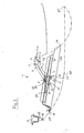
- Mounting device 41 shown for mounting a shell-sliding door 42 on a shell body of the motor vehicle during a painting process comprises a body connection 43 and a door connection 44.
- the body connection 43 comprises a mounting frame 45, which on the B-pillar 2 and on the C-pillar 3 of Body shell is mounted.
- the mounting frame 45 is provided at its front and rear ends with mounting brackets 46, 47.
- one leg of the mounting bracket 46, 47 abuts the B-pillar 2 and the C-pillar 3.
- the respective leg is detachably connected there to the B-pillar 2 and the C-pillar 3.
- the mounting brackets 46, 47 are bolted to the B-pillar 2 and the C-pillar 3.
- the door connection 44 includes a mounting frame 48 which is mounted on the shell sliding door 42.
- the mounting frame 48 at its ends mounting bracket 49, 50, of which one leg with the inner panel 51 of the shell sliding door 42 is releasably connected.
- the legs of the mounting brackets 49, 50 are bolted to the inner panel 51.
- the body connection 43 and the door connection 44 are connected to each other by a multi-joint 52.
- the multi-joint 52 comprises, similar to the multi-joint of the finished sliding door 1, a hinge bracket 7 ', which is pivotally mounted on the mounting frame 45 about a hinge 9' and on the mounting frame 48 about a hinge 8 ', and a control lever 11', the on the mounting frame 45 about a hinge 13 'and on the mounting frame 48 about a hinge 12' is pivotally mounted.
- the joint 13 ' is located substantially in the middle of the mounting frame 45 and in the vehicle transverse direction within the connecting line of the B-pillar 2 with the C-pillar 3.
- the joint 9' is located in the vehicle longitudinal direction in front of the joint 13 'and in the vehicle transverse direction within the Joint 13 '.
- the joint 8 ' is located in the vehicle longitudinal direction behind the B-pillar 2 and in front of the joints 13' and 9 '. It is located in the vehicle transverse direction outside of the joint 13 '.
- the joint 12 ' is located in the vehicle longitudinal direction behind the joint 8' and in front of the joint 9 '. It is located in the vehicle transverse direction outside of the joint 8 '.
- Fig. 4 shows the mounting device in the closed position.
- FIG. 5 shows the fully open position of the shell sliding door 42.
- the hinge bracket 7 ' has been about the hinge 9' and the control lever 11 'has been pivoted about the hinge 13' respectively counterclockwise.
- the mounting of the mounting device 41 can take place in the following steps: First, the body connection 43 and the door connection 44 are connected to each other by the multi-joint 52. Subsequently, the door connection 44 is mounted on the shell sliding door 42. The thus assembled unit, consisting of the mounting device 41 and the shell sliding door 42, is finally positioned on the shell body, so on the B-pillar 2 and the C-pillar 3, and the body connection 43 is on the shell body, so on the B-pillar 2 and the C-pillar 3, mounted.
- the mounting device 41 can be dismantled again. This is preferably done in reverse order. However, it is advantageous not to solve the connection of the body connection 43 and the door connection 44 through the multi-joint 52, but only to dismantle the door connection 44 of the shell sliding door 42 and the body connection 43 of the bodyshell, ie of the B-pillar. 2 and from the C-pillar 3, to dismantle.
- the mounting device 41 consisting of the body joint 43 connected by the multi-joint 52 and the door connection 44, can then be used for the next painting process of the next shell sliding door and the next shell body.
- a sliding door 1 or a different kind of sliding door can be produced after painting.
Landscapes
- Engineering & Computer Science (AREA)
- Mechanical Engineering (AREA)
- Automobile Manufacture Line, Endless Track Vehicle, Trailer (AREA)
- Wing Frames And Configurations (AREA)
- Spray Control Apparatus (AREA)
- Body Structure For Vehicles (AREA)
Applications Claiming Priority (1)
| Application Number | Priority Date | Filing Date | Title |
|---|---|---|---|
| DE102009057301A DE102009057301A1 (de) | 2009-12-07 | 2009-12-07 | Montagevorrichtung zum Montieren einer Rohbau-Schiebetüre eines Kraftfahrzeugs |
Publications (3)
| Publication Number | Publication Date |
|---|---|
| EP2332659A2 true EP2332659A2 (fr) | 2011-06-15 |
| EP2332659A3 EP2332659A3 (fr) | 2013-04-17 |
| EP2332659B1 EP2332659B1 (fr) | 2018-03-28 |
Family
ID=43447732
Family Applications (1)
| Application Number | Title | Priority Date | Filing Date |
|---|---|---|---|
| EP10014039.1A Not-in-force EP2332659B1 (fr) | 2009-12-07 | 2010-10-27 | Dispositif de montage destiné au montage d'une porte coulissante de gros oeuvre d'un véhicule automobile |
Country Status (4)
| Country | Link |
|---|---|
| US (1) | US8765227B2 (fr) |
| EP (1) | EP2332659B1 (fr) |
| CN (1) | CN102085889B (fr) |
| DE (1) | DE102009057301A1 (fr) |
Families Citing this family (7)
| Publication number | Priority date | Publication date | Assignee | Title |
|---|---|---|---|---|
| US10876341B2 (en) * | 2018-07-24 | 2020-12-29 | Brose Fahrzeugteile Gmbh & Co. Kommanditgesellschaft, Bamberg | Door drive system |
| GB2582549B (en) * | 2019-03-19 | 2023-09-13 | Jaguar Land Rover Ltd | Hinge apparatus |
| CN110170405B (zh) * | 2019-07-05 | 2024-12-17 | 安徽安凯汽车股份有限公司 | 一种用于乘客门油漆喷涂的夹紧工装 |
| US20220389743A1 (en) * | 2021-06-02 | 2022-12-08 | Magna BOCO GmbH | Power door linkage system for b-pillarless door system for motor vehicles |
| CN114454696B (zh) * | 2022-02-21 | 2024-03-08 | 重庆长安汽车股份有限公司 | 一种车辆的无轨侧滑门机械结构 |
| CN114522830B (zh) * | 2022-03-28 | 2025-11-25 | 广汽丰田汽车有限公司 | 用于辅助车辆车门涂装的工装 |
| CN119711853B (zh) * | 2025-01-20 | 2026-02-24 | 东风汽车股份有限公司 | 一种大开启角度自限位背门铰链 |
Citations (2)
| Publication number | Priority date | Publication date | Assignee | Title |
|---|---|---|---|---|
| EP2008846A2 (fr) | 2007-06-28 | 2008-12-31 | DURA Automotive Body and Glass Systems GmbH | Porte coulissante pour véhicule |
| DE102008016650B3 (de) | 2008-04-01 | 2009-05-14 | Dura Automotive Body & Glass Systems Gmbh | Schiebetüre für ein Fahrzeug |
Family Cites Families (9)
| Publication number | Priority date | Publication date | Assignee | Title |
|---|---|---|---|---|
| JP3517823B2 (ja) * | 1998-03-16 | 2004-04-12 | 本田技研工業株式会社 | 塗装用ドア治具を選定する方法およびそのための治具 |
| US6199849B1 (en) * | 1998-09-29 | 2001-03-13 | Chrysler Corporation | Device for momentarily mounting a sliding door to a vehicle body |
| FR2835233B1 (fr) * | 2002-01-28 | 2004-04-09 | Jefmag | Ecarteur pour porte de vehicule automobile |
| KR100527481B1 (ko) * | 2003-09-15 | 2005-11-09 | 현대자동차주식회사 | 차량 도어힌지 장착장치 |
| CN1640708A (zh) * | 2004-01-16 | 2005-07-20 | 台达电子工业股份有限公司 | 滑动式车门及其安全装置 |
| US20060068094A1 (en) * | 2004-09-29 | 2006-03-30 | Cole David J | Production paint shop design |
| WO2008154237A1 (fr) * | 2007-06-07 | 2008-12-18 | Utica Enterprises, Inc. | Montage de portière de véhicule |
| JP4914841B2 (ja) * | 2008-01-09 | 2012-04-11 | 本田技研工業株式会社 | 車両のスライドドア構造 |
| DE102008026137B4 (de) | 2008-05-30 | 2013-01-03 | Dura Automotive Body & Glass Systems Gmbh | Schiebetüre für ein Fahrzeug |
-
2009
- 2009-12-07 DE DE102009057301A patent/DE102009057301A1/de not_active Withdrawn
-
2010
- 2010-10-27 EP EP10014039.1A patent/EP2332659B1/fr not_active Not-in-force
- 2010-12-06 US US12/960,995 patent/US8765227B2/en not_active Expired - Fee Related
- 2010-12-07 CN CN201010585509.9A patent/CN102085889B/zh not_active Expired - Fee Related
Patent Citations (2)
| Publication number | Priority date | Publication date | Assignee | Title |
|---|---|---|---|---|
| EP2008846A2 (fr) | 2007-06-28 | 2008-12-31 | DURA Automotive Body and Glass Systems GmbH | Porte coulissante pour véhicule |
| DE102008016650B3 (de) | 2008-04-01 | 2009-05-14 | Dura Automotive Body & Glass Systems Gmbh | Schiebetüre für ein Fahrzeug |
Also Published As
| Publication number | Publication date |
|---|---|
| US20110135826A1 (en) | 2011-06-09 |
| EP2332659B1 (fr) | 2018-03-28 |
| EP2332659A3 (fr) | 2013-04-17 |
| CN102085889A (zh) | 2011-06-08 |
| DE102009057301A1 (de) | 2011-06-09 |
| US8765227B2 (en) | 2014-07-01 |
| CN102085889B (zh) | 2015-02-11 |
Similar Documents
| Publication | Publication Date | Title |
|---|---|---|
| EP2257443B1 (fr) | Portière coulissante pour un véhicule | |
| EP2008846B1 (fr) | Porte coulissante pour véhicule | |
| EP2332659B1 (fr) | Dispositif de montage destiné au montage d'une porte coulissante de gros oeuvre d'un véhicule automobile | |
| EP3216958B1 (fr) | Ferrure pour un battant coulissant | |
| EP2127928B1 (fr) | Porte coulissante pour véhicule | |
| EP2332759B1 (fr) | Véhicule doté d'une porte coulissante | |
| EP1688568A2 (fr) | Porte, en particulier pour véhicule automobile | |
| EP1310621A2 (fr) | Assemblage de porte pour véhicule | |
| EP2329975B1 (fr) | Porte coulissante pour véhicule | |
| EP2329976B1 (fr) | Porte coulissante pour véhicule | |
| DE102009058583B4 (de) | Schiebetüre für ein Fahrzeug | |
| DE102014003396A1 (de) | Halteanordnung zweier Seitentüren an einer Karosserie eines Personenkraftwagens | |
| EP3791035B1 (fr) | Ensemble formant ferrure pour une fenêtre coulissante ou une porte coulissante | |
| DE102007006518B4 (de) | Anlenkung für einen Heckdeckel | |
| EP1758752B1 (fr) | Voiture cabriolet | |
| DE10156011A1 (de) | Verstellbares Deckelelement in einem Fahrzeug | |
| EP1264718A1 (fr) | Porte de véhicule avec des biellettes pour ouverture en forme d'un parallélogramme | |
| DE102016205426A1 (de) | Scharniervorrichtung zur Verwendung in einem Kraftfahrzeug, Kraftfahrzeugtür mit einer solchen Scharniervorrichtung und hiermit ausgestattetes Kraftfahrzeug | |
| DE4446904C1 (de) | Kraftfahrzeug-Türgriff | |
| DE102005061978B3 (de) | Scharniervorrichtung | |
| DE102009058584B4 (de) | Schiebetüre für ein Fahrzeug | |
| WO2009000548A2 (fr) | Porte coulissante pour un véhicule | |
| DE102007006266A1 (de) | Führungseinrichtung für eine Schiebetür eines Kraftwagens | |
| DE102008036907A1 (de) | Faltverdeck für einen Personenkraftwagen | |
| DE102007056634A1 (de) | Cabriolet-Fahrzeug |
Legal Events
| Date | Code | Title | Description |
|---|---|---|---|
| PUAI | Public reference made under article 153(3) epc to a published international application that has entered the european phase |
Free format text: ORIGINAL CODE: 0009012 |
|
| AK | Designated contracting states |
Kind code of ref document: A2 Designated state(s): AL AT BE BG CH CY CZ DE DK EE ES FI FR GB GR HR HU IE IS IT LI LT LU LV MC MK MT NL NO PL PT RO RS SE SI SK SM TR |
|
| AX | Request for extension of the european patent |
Extension state: BA ME |
|
| PUAL | Search report despatched |
Free format text: ORIGINAL CODE: 0009013 |
|
| AK | Designated contracting states |
Kind code of ref document: A3 Designated state(s): AL AT BE BG CH CY CZ DE DK EE ES FI FR GB GR HR HU IE IS IT LI LT LU LV MC MK MT NL NO PL PT RO RS SE SI SK SM TR |
|
| AX | Request for extension of the european patent |
Extension state: BA ME |
|
| RIC1 | Information provided on ipc code assigned before grant |
Ipc: E05D 3/14 20060101ALN20130313BHEP Ipc: B60J 5/06 20060101ALI20130313BHEP Ipc: B05B 13/02 20060101AFI20130313BHEP Ipc: B60J 5/00 20060101ALI20130313BHEP |
|
| 17P | Request for examination filed |
Effective date: 20131017 |
|
| RBV | Designated contracting states (corrected) |
Designated state(s): AL AT BE BG CH CY CZ DE DK EE ES FI FR GB GR HR HU IE IS IT LI LT LU LV MC MK MT NL NO PL PT RO RS SE SI SK SM TR |
|
| 17Q | First examination report despatched |
Effective date: 20161124 |
|
| RAP1 | Party data changed (applicant data changed or rights of an application transferred) |
Owner name: DURA AUTOMOTIVE HOLDINGS U.K., LTD. |
|
| RIC1 | Information provided on ipc code assigned before grant |
Ipc: B60J 5/06 20060101ALI20170908BHEP Ipc: B05B 13/02 20060101AFI20170908BHEP Ipc: B60J 5/00 20060101ALI20170908BHEP Ipc: E05D 3/14 20060101ALN20170908BHEP |
|
| GRAP | Despatch of communication of intention to grant a patent |
Free format text: ORIGINAL CODE: EPIDOSNIGR1 |
|
| INTG | Intention to grant announced |
Effective date: 20171024 |
|
| GRAS | Grant fee paid |
Free format text: ORIGINAL CODE: EPIDOSNIGR3 |
|
| GRAA | (expected) grant |
Free format text: ORIGINAL CODE: 0009210 |
|
| AK | Designated contracting states |
Kind code of ref document: B1 Designated state(s): AL AT BE BG CH CY CZ DE DK EE ES FI FR GB GR HR HU IE IS IT LI LT LU LV MC MK MT NL NO PL PT RO RS SE SI SK SM TR |
|
| REG | Reference to a national code |
Ref country code: GB Ref legal event code: FG4D Free format text: NOT ENGLISH |
|
| REG | Reference to a national code |
Ref country code: CH Ref legal event code: EP |
|
| REG | Reference to a national code |
Ref country code: AT Ref legal event code: REF Ref document number: 982930 Country of ref document: AT Kind code of ref document: T Effective date: 20180415 |
|
| REG | Reference to a national code |
Ref country code: IE Ref legal event code: FG4D Free format text: LANGUAGE OF EP DOCUMENT: GERMAN |
|
| REG | Reference to a national code |
Ref country code: DE Ref legal event code: R096 Ref document number: 502010014795 Country of ref document: DE |
|
| PG25 | Lapsed in a contracting state [announced via postgrant information from national office to epo] |
Ref country code: HR Free format text: LAPSE BECAUSE OF FAILURE TO SUBMIT A TRANSLATION OF THE DESCRIPTION OR TO PAY THE FEE WITHIN THE PRESCRIBED TIME-LIMIT Effective date: 20180328 Ref country code: LT Free format text: LAPSE BECAUSE OF FAILURE TO SUBMIT A TRANSLATION OF THE DESCRIPTION OR TO PAY THE FEE WITHIN THE PRESCRIBED TIME-LIMIT Effective date: 20180328 Ref country code: NO Free format text: LAPSE BECAUSE OF FAILURE TO SUBMIT A TRANSLATION OF THE DESCRIPTION OR TO PAY THE FEE WITHIN THE PRESCRIBED TIME-LIMIT Effective date: 20180628 Ref country code: FI Free format text: LAPSE BECAUSE OF FAILURE TO SUBMIT A TRANSLATION OF THE DESCRIPTION OR TO PAY THE FEE WITHIN THE PRESCRIBED TIME-LIMIT Effective date: 20180328 |
|
| REG | Reference to a national code |
Ref country code: NL Ref legal event code: MP Effective date: 20180328 |
|
| REG | Reference to a national code |
Ref country code: LT Ref legal event code: MG4D |
|
| PG25 | Lapsed in a contracting state [announced via postgrant information from national office to epo] |
Ref country code: LV Free format text: LAPSE BECAUSE OF FAILURE TO SUBMIT A TRANSLATION OF THE DESCRIPTION OR TO PAY THE FEE WITHIN THE PRESCRIBED TIME-LIMIT Effective date: 20180328 Ref country code: SE Free format text: LAPSE BECAUSE OF FAILURE TO SUBMIT A TRANSLATION OF THE DESCRIPTION OR TO PAY THE FEE WITHIN THE PRESCRIBED TIME-LIMIT Effective date: 20180328 Ref country code: RS Free format text: LAPSE BECAUSE OF FAILURE TO SUBMIT A TRANSLATION OF THE DESCRIPTION OR TO PAY THE FEE WITHIN THE PRESCRIBED TIME-LIMIT Effective date: 20180328 Ref country code: BG Free format text: LAPSE BECAUSE OF FAILURE TO SUBMIT A TRANSLATION OF THE DESCRIPTION OR TO PAY THE FEE WITHIN THE PRESCRIBED TIME-LIMIT Effective date: 20180628 Ref country code: GR Free format text: LAPSE BECAUSE OF FAILURE TO SUBMIT A TRANSLATION OF THE DESCRIPTION OR TO PAY THE FEE WITHIN THE PRESCRIBED TIME-LIMIT Effective date: 20180629 |
|
| PG25 | Lapsed in a contracting state [announced via postgrant information from national office to epo] |
Ref country code: MT Free format text: LAPSE BECAUSE OF FAILURE TO SUBMIT A TRANSLATION OF THE DESCRIPTION OR TO PAY THE FEE WITHIN THE PRESCRIBED TIME-LIMIT Effective date: 20180328 |
|
| PG25 | Lapsed in a contracting state [announced via postgrant information from national office to epo] |
Ref country code: EE Free format text: LAPSE BECAUSE OF FAILURE TO SUBMIT A TRANSLATION OF THE DESCRIPTION OR TO PAY THE FEE WITHIN THE PRESCRIBED TIME-LIMIT Effective date: 20180328 Ref country code: RO Free format text: LAPSE BECAUSE OF FAILURE TO SUBMIT A TRANSLATION OF THE DESCRIPTION OR TO PAY THE FEE WITHIN THE PRESCRIBED TIME-LIMIT Effective date: 20180328 Ref country code: IT Free format text: LAPSE BECAUSE OF FAILURE TO SUBMIT A TRANSLATION OF THE DESCRIPTION OR TO PAY THE FEE WITHIN THE PRESCRIBED TIME-LIMIT Effective date: 20180328 Ref country code: ES Free format text: LAPSE BECAUSE OF FAILURE TO SUBMIT A TRANSLATION OF THE DESCRIPTION OR TO PAY THE FEE WITHIN THE PRESCRIBED TIME-LIMIT Effective date: 20180328 Ref country code: AL Free format text: LAPSE BECAUSE OF FAILURE TO SUBMIT A TRANSLATION OF THE DESCRIPTION OR TO PAY THE FEE WITHIN THE PRESCRIBED TIME-LIMIT Effective date: 20180328 Ref country code: NL Free format text: LAPSE BECAUSE OF FAILURE TO SUBMIT A TRANSLATION OF THE DESCRIPTION OR TO PAY THE FEE WITHIN THE PRESCRIBED TIME-LIMIT Effective date: 20180328 Ref country code: PL Free format text: LAPSE BECAUSE OF FAILURE TO SUBMIT A TRANSLATION OF THE DESCRIPTION OR TO PAY THE FEE WITHIN THE PRESCRIBED TIME-LIMIT Effective date: 20180328 |
|
| PG25 | Lapsed in a contracting state [announced via postgrant information from national office to epo] |
Ref country code: SK Free format text: LAPSE BECAUSE OF FAILURE TO SUBMIT A TRANSLATION OF THE DESCRIPTION OR TO PAY THE FEE WITHIN THE PRESCRIBED TIME-LIMIT Effective date: 20180328 Ref country code: SM Free format text: LAPSE BECAUSE OF FAILURE TO SUBMIT A TRANSLATION OF THE DESCRIPTION OR TO PAY THE FEE WITHIN THE PRESCRIBED TIME-LIMIT Effective date: 20180328 Ref country code: CZ Free format text: LAPSE BECAUSE OF FAILURE TO SUBMIT A TRANSLATION OF THE DESCRIPTION OR TO PAY THE FEE WITHIN THE PRESCRIBED TIME-LIMIT Effective date: 20180328 |
|
| PG25 | Lapsed in a contracting state [announced via postgrant information from national office to epo] |
Ref country code: PT Free format text: LAPSE BECAUSE OF FAILURE TO SUBMIT A TRANSLATION OF THE DESCRIPTION OR TO PAY THE FEE WITHIN THE PRESCRIBED TIME-LIMIT Effective date: 20180730 |
|
| REG | Reference to a national code |
Ref country code: DE Ref legal event code: R097 Ref document number: 502010014795 Country of ref document: DE |
|
| PG25 | Lapsed in a contracting state [announced via postgrant information from national office to epo] |
Ref country code: DK Free format text: LAPSE BECAUSE OF FAILURE TO SUBMIT A TRANSLATION OF THE DESCRIPTION OR TO PAY THE FEE WITHIN THE PRESCRIBED TIME-LIMIT Effective date: 20180328 |
|
| PGFP | Annual fee paid to national office [announced via postgrant information from national office to epo] |
Ref country code: DE Payment date: 20181128 Year of fee payment: 9 |
|
| PLBE | No opposition filed within time limit |
Free format text: ORIGINAL CODE: 0009261 |
|
| STAA | Information on the status of an ep patent application or granted ep patent |
Free format text: STATUS: NO OPPOSITION FILED WITHIN TIME LIMIT |
|
| PGFP | Annual fee paid to national office [announced via postgrant information from national office to epo] |
Ref country code: GB Payment date: 20181127 Year of fee payment: 9 Ref country code: FR Payment date: 20181127 Year of fee payment: 9 |
|
| 26N | No opposition filed |
Effective date: 20190103 |
|
| PG25 | Lapsed in a contracting state [announced via postgrant information from national office to epo] |
Ref country code: SI Free format text: LAPSE BECAUSE OF FAILURE TO SUBMIT A TRANSLATION OF THE DESCRIPTION OR TO PAY THE FEE WITHIN THE PRESCRIBED TIME-LIMIT Effective date: 20180328 |
|
| REG | Reference to a national code |
Ref country code: CH Ref legal event code: PL |
|
| REG | Reference to a national code |
Ref country code: BE Ref legal event code: MM Effective date: 20181031 |
|
| PG25 | Lapsed in a contracting state [announced via postgrant information from national office to epo] |
Ref country code: LU Free format text: LAPSE BECAUSE OF NON-PAYMENT OF DUE FEES Effective date: 20181027 Ref country code: MC Free format text: LAPSE BECAUSE OF FAILURE TO SUBMIT A TRANSLATION OF THE DESCRIPTION OR TO PAY THE FEE WITHIN THE PRESCRIBED TIME-LIMIT Effective date: 20180328 |
|
| REG | Reference to a national code |
Ref country code: IE Ref legal event code: MM4A |
|
| PG25 | Lapsed in a contracting state [announced via postgrant information from national office to epo] |
Ref country code: CH Free format text: LAPSE BECAUSE OF NON-PAYMENT OF DUE FEES Effective date: 20181031 Ref country code: BE Free format text: LAPSE BECAUSE OF NON-PAYMENT OF DUE FEES Effective date: 20181031 Ref country code: LI Free format text: LAPSE BECAUSE OF NON-PAYMENT OF DUE FEES Effective date: 20181031 |
|
| PG25 | Lapsed in a contracting state [announced via postgrant information from national office to epo] |
Ref country code: IE Free format text: LAPSE BECAUSE OF NON-PAYMENT OF DUE FEES Effective date: 20181027 |
|
| REG | Reference to a national code |
Ref country code: AT Ref legal event code: MM01 Ref document number: 982930 Country of ref document: AT Kind code of ref document: T Effective date: 20181027 |
|
| PG25 | Lapsed in a contracting state [announced via postgrant information from national office to epo] |
Ref country code: AT Free format text: LAPSE BECAUSE OF NON-PAYMENT OF DUE FEES Effective date: 20181027 |
|
| PG25 | Lapsed in a contracting state [announced via postgrant information from national office to epo] |
Ref country code: TR Free format text: LAPSE BECAUSE OF FAILURE TO SUBMIT A TRANSLATION OF THE DESCRIPTION OR TO PAY THE FEE WITHIN THE PRESCRIBED TIME-LIMIT Effective date: 20180328 |
|
| REG | Reference to a national code |
Ref country code: DE Ref legal event code: R119 Ref document number: 502010014795 Country of ref document: DE |
|
| PG25 | Lapsed in a contracting state [announced via postgrant information from national office to epo] |
Ref country code: MK Free format text: LAPSE BECAUSE OF NON-PAYMENT OF DUE FEES Effective date: 20180328 Ref country code: CY Free format text: LAPSE BECAUSE OF FAILURE TO SUBMIT A TRANSLATION OF THE DESCRIPTION OR TO PAY THE FEE WITHIN THE PRESCRIBED TIME-LIMIT Effective date: 20180328 Ref country code: HU Free format text: LAPSE BECAUSE OF FAILURE TO SUBMIT A TRANSLATION OF THE DESCRIPTION OR TO PAY THE FEE WITHIN THE PRESCRIBED TIME-LIMIT; INVALID AB INITIO Effective date: 20101027 |
|
| PG25 | Lapsed in a contracting state [announced via postgrant information from national office to epo] |
Ref country code: DE Free format text: LAPSE BECAUSE OF NON-PAYMENT OF DUE FEES Effective date: 20200501 Ref country code: IS Free format text: LAPSE BECAUSE OF FAILURE TO SUBMIT A TRANSLATION OF THE DESCRIPTION OR TO PAY THE FEE WITHIN THE PRESCRIBED TIME-LIMIT Effective date: 20180728 |
|
| GBPC | Gb: european patent ceased through non-payment of renewal fee |
Effective date: 20191027 |
|
| PG25 | Lapsed in a contracting state [announced via postgrant information from national office to epo] |
Ref country code: GB Free format text: LAPSE BECAUSE OF NON-PAYMENT OF DUE FEES Effective date: 20191027 Ref country code: FR Free format text: LAPSE BECAUSE OF NON-PAYMENT OF DUE FEES Effective date: 20191031 |