EP2332798B1 - Fahrzeug, fahrzeugsteuerungsverfahren und steuervorrichtung - Google Patents
Fahrzeug, fahrzeugsteuerungsverfahren und steuervorrichtung Download PDFInfo
- Publication number
- EP2332798B1 EP2332798B1 EP09811330.1A EP09811330A EP2332798B1 EP 2332798 B1 EP2332798 B1 EP 2332798B1 EP 09811330 A EP09811330 A EP 09811330A EP 2332798 B1 EP2332798 B1 EP 2332798B1
- Authority
- EP
- European Patent Office
- Prior art keywords
- battery
- electric power
- charge
- state
- vehicle
- Prior art date
- Legal status (The legal status is an assumption and is not a legal conclusion. Google has not performed a legal analysis and makes no representation as to the accuracy of the status listed.)
- Not-in-force
Links
Images


Classifications
-
- B—PERFORMING OPERATIONS; TRANSPORTING
- B60—VEHICLES IN GENERAL
- B60W—CONJOINT CONTROL OF VEHICLE SUB-UNITS OF DIFFERENT TYPE OR DIFFERENT FUNCTION; CONTROL SYSTEMS SPECIALLY ADAPTED FOR HYBRID VEHICLES; ROAD VEHICLE DRIVE CONTROL SYSTEMS FOR PURPOSES NOT RELATED TO THE CONTROL OF A PARTICULAR SUB-UNIT
- B60W20/00—Control systems specially adapted for hybrid vehicles
- B60W20/10—Controlling the power contribution of each of the prime movers to meet required power demand
- B60W20/13—Controlling the power contribution of each of the prime movers to meet required power demand in order to stay within battery power input or output limits; in order to prevent overcharging or battery depletion
-
- B—PERFORMING OPERATIONS; TRANSPORTING
- B60—VEHICLES IN GENERAL
- B60K—ARRANGEMENT OR MOUNTING OF PROPULSION UNITS OR OF TRANSMISSIONS IN VEHICLES; ARRANGEMENT OR MOUNTING OF PLURAL DIVERSE PRIME-MOVERS IN VEHICLES; AUXILIARY DRIVES FOR VEHICLES; INSTRUMENTATION OR DASHBOARDS FOR VEHICLES; ARRANGEMENTS IN CONNECTION WITH COOLING, AIR INTAKE, GAS EXHAUST OR FUEL SUPPLY OF PROPULSION UNITS IN VEHICLES
- B60K6/00—Arrangement or mounting of plural diverse prime-movers for mutual or common propulsion, e.g. hybrid propulsion systems comprising electric motors and internal combustion engines
- B60K6/20—Arrangement or mounting of plural diverse prime-movers for mutual or common propulsion, e.g. hybrid propulsion systems comprising electric motors and internal combustion engines the prime-movers consisting of electric motors and internal combustion engines, e.g. HEVs
- B60K6/22—Arrangement or mounting of plural diverse prime-movers for mutual or common propulsion, e.g. hybrid propulsion systems comprising electric motors and internal combustion engines the prime-movers consisting of electric motors and internal combustion engines, e.g. HEVs characterised by apparatus, components or means specially adapted for HEVs
- B60K6/28—Arrangement or mounting of plural diverse prime-movers for mutual or common propulsion, e.g. hybrid propulsion systems comprising electric motors and internal combustion engines the prime-movers consisting of electric motors and internal combustion engines, e.g. HEVs characterised by apparatus, components or means specially adapted for HEVs characterised by the electric energy storing means, e.g. batteries or capacitors
-
- B—PERFORMING OPERATIONS; TRANSPORTING
- B60—VEHICLES IN GENERAL
- B60K—ARRANGEMENT OR MOUNTING OF PROPULSION UNITS OR OF TRANSMISSIONS IN VEHICLES; ARRANGEMENT OR MOUNTING OF PLURAL DIVERSE PRIME-MOVERS IN VEHICLES; AUXILIARY DRIVES FOR VEHICLES; INSTRUMENTATION OR DASHBOARDS FOR VEHICLES; ARRANGEMENTS IN CONNECTION WITH COOLING, AIR INTAKE, GAS EXHAUST OR FUEL SUPPLY OF PROPULSION UNITS IN VEHICLES
- B60K6/00—Arrangement or mounting of plural diverse prime-movers for mutual or common propulsion, e.g. hybrid propulsion systems comprising electric motors and internal combustion engines
- B60K6/20—Arrangement or mounting of plural diverse prime-movers for mutual or common propulsion, e.g. hybrid propulsion systems comprising electric motors and internal combustion engines the prime-movers consisting of electric motors and internal combustion engines, e.g. HEVs
- B60K6/42—Arrangement or mounting of plural diverse prime-movers for mutual or common propulsion, e.g. hybrid propulsion systems comprising electric motors and internal combustion engines the prime-movers consisting of electric motors and internal combustion engines, e.g. HEVs characterised by the architecture of the hybrid electric vehicle
- B60K6/44—Series-parallel type
- B60K6/445—Differential gearing distribution type
-
- B—PERFORMING OPERATIONS; TRANSPORTING
- B60—VEHICLES IN GENERAL
- B60L—PROPULSION OF ELECTRICALLY-PROPELLED VEHICLES; SUPPLYING ELECTRIC POWER FOR AUXILIARY EQUIPMENT OF ELECTRICALLY-PROPELLED VEHICLES; ELECTRODYNAMIC BRAKE SYSTEMS FOR VEHICLES IN GENERAL; MAGNETIC SUSPENSION OR LEVITATION FOR VEHICLES; MONITORING OPERATING VARIABLES OF ELECTRICALLY-PROPELLED VEHICLES; ELECTRIC SAFETY DEVICES FOR ELECTRICALLY-PROPELLED VEHICLES
- B60L50/00—Electric propulsion with power supplied within the vehicle
- B60L50/10—Electric propulsion with power supplied within the vehicle using propulsion power supplied by engine-driven generators, e.g. generators driven by combustion engines
- B60L50/16—Electric propulsion with power supplied within the vehicle using propulsion power supplied by engine-driven generators, e.g. generators driven by combustion engines with provision for separate direct mechanical propulsion
-
- B—PERFORMING OPERATIONS; TRANSPORTING
- B60—VEHICLES IN GENERAL
- B60L—PROPULSION OF ELECTRICALLY-PROPELLED VEHICLES; SUPPLYING ELECTRIC POWER FOR AUXILIARY EQUIPMENT OF ELECTRICALLY-PROPELLED VEHICLES; ELECTRODYNAMIC BRAKE SYSTEMS FOR VEHICLES IN GENERAL; MAGNETIC SUSPENSION OR LEVITATION FOR VEHICLES; MONITORING OPERATING VARIABLES OF ELECTRICALLY-PROPELLED VEHICLES; ELECTRIC SAFETY DEVICES FOR ELECTRICALLY-PROPELLED VEHICLES
- B60L50/00—Electric propulsion with power supplied within the vehicle
- B60L50/50—Electric propulsion with power supplied within the vehicle using propulsion power supplied by batteries or fuel cells
- B60L50/60—Electric propulsion with power supplied within the vehicle using propulsion power supplied by batteries or fuel cells using power supplied by batteries
- B60L50/61—Electric propulsion with power supplied within the vehicle using propulsion power supplied by batteries or fuel cells using power supplied by batteries by batteries charged by engine-driven generators, e.g. series hybrid electric vehicles
-
- B—PERFORMING OPERATIONS; TRANSPORTING
- B60—VEHICLES IN GENERAL
- B60L—PROPULSION OF ELECTRICALLY-PROPELLED VEHICLES; SUPPLYING ELECTRIC POWER FOR AUXILIARY EQUIPMENT OF ELECTRICALLY-PROPELLED VEHICLES; ELECTRODYNAMIC BRAKE SYSTEMS FOR VEHICLES IN GENERAL; MAGNETIC SUSPENSION OR LEVITATION FOR VEHICLES; MONITORING OPERATING VARIABLES OF ELECTRICALLY-PROPELLED VEHICLES; ELECTRIC SAFETY DEVICES FOR ELECTRICALLY-PROPELLED VEHICLES
- B60L58/00—Methods or circuit arrangements for monitoring or controlling batteries or fuel cells, specially adapted for electric vehicles
- B60L58/10—Methods or circuit arrangements for monitoring or controlling batteries or fuel cells, specially adapted for electric vehicles for monitoring or controlling batteries
- B60L58/12—Methods or circuit arrangements for monitoring or controlling batteries or fuel cells, specially adapted for electric vehicles for monitoring or controlling batteries responding to state of charge [SoC]
-
- B—PERFORMING OPERATIONS; TRANSPORTING
- B60—VEHICLES IN GENERAL
- B60L—PROPULSION OF ELECTRICALLY-PROPELLED VEHICLES; SUPPLYING ELECTRIC POWER FOR AUXILIARY EQUIPMENT OF ELECTRICALLY-PROPELLED VEHICLES; ELECTRODYNAMIC BRAKE SYSTEMS FOR VEHICLES IN GENERAL; MAGNETIC SUSPENSION OR LEVITATION FOR VEHICLES; MONITORING OPERATING VARIABLES OF ELECTRICALLY-PROPELLED VEHICLES; ELECTRIC SAFETY DEVICES FOR ELECTRICALLY-PROPELLED VEHICLES
- B60L58/00—Methods or circuit arrangements for monitoring or controlling batteries or fuel cells, specially adapted for electric vehicles
- B60L58/10—Methods or circuit arrangements for monitoring or controlling batteries or fuel cells, specially adapted for electric vehicles for monitoring or controlling batteries
- B60L58/18—Methods or circuit arrangements for monitoring or controlling batteries or fuel cells, specially adapted for electric vehicles for monitoring or controlling batteries of two or more battery modules
- B60L58/19—Switching between serial connection and parallel connection of battery modules
-
- B—PERFORMING OPERATIONS; TRANSPORTING
- B60—VEHICLES IN GENERAL
- B60L—PROPULSION OF ELECTRICALLY-PROPELLED VEHICLES; SUPPLYING ELECTRIC POWER FOR AUXILIARY EQUIPMENT OF ELECTRICALLY-PROPELLED VEHICLES; ELECTRODYNAMIC BRAKE SYSTEMS FOR VEHICLES IN GENERAL; MAGNETIC SUSPENSION OR LEVITATION FOR VEHICLES; MONITORING OPERATING VARIABLES OF ELECTRICALLY-PROPELLED VEHICLES; ELECTRIC SAFETY DEVICES FOR ELECTRICALLY-PROPELLED VEHICLES
- B60L58/00—Methods or circuit arrangements for monitoring or controlling batteries or fuel cells, specially adapted for electric vehicles
- B60L58/10—Methods or circuit arrangements for monitoring or controlling batteries or fuel cells, specially adapted for electric vehicles for monitoring or controlling batteries
- B60L58/18—Methods or circuit arrangements for monitoring or controlling batteries or fuel cells, specially adapted for electric vehicles for monitoring or controlling batteries of two or more battery modules
- B60L58/21—Methods or circuit arrangements for monitoring or controlling batteries or fuel cells, specially adapted for electric vehicles for monitoring or controlling batteries of two or more battery modules having the same nominal voltage
-
- B—PERFORMING OPERATIONS; TRANSPORTING
- B60—VEHICLES IN GENERAL
- B60W—CONJOINT CONTROL OF VEHICLE SUB-UNITS OF DIFFERENT TYPE OR DIFFERENT FUNCTION; CONTROL SYSTEMS SPECIALLY ADAPTED FOR HYBRID VEHICLES; ROAD VEHICLE DRIVE CONTROL SYSTEMS FOR PURPOSES NOT RELATED TO THE CONTROL OF A PARTICULAR SUB-UNIT
- B60W10/00—Conjoint control of vehicle sub-units of different type or different function
- B60W10/04—Conjoint control of vehicle sub-units of different type or different function including control of propulsion units
- B60W10/06—Conjoint control of vehicle sub-units of different type or different function including control of propulsion units including control of combustion engines
-
- B—PERFORMING OPERATIONS; TRANSPORTING
- B60—VEHICLES IN GENERAL
- B60W—CONJOINT CONTROL OF VEHICLE SUB-UNITS OF DIFFERENT TYPE OR DIFFERENT FUNCTION; CONTROL SYSTEMS SPECIALLY ADAPTED FOR HYBRID VEHICLES; ROAD VEHICLE DRIVE CONTROL SYSTEMS FOR PURPOSES NOT RELATED TO THE CONTROL OF A PARTICULAR SUB-UNIT
- B60W10/00—Conjoint control of vehicle sub-units of different type or different function
- B60W10/04—Conjoint control of vehicle sub-units of different type or different function including control of propulsion units
- B60W10/08—Conjoint control of vehicle sub-units of different type or different function including control of propulsion units including control of electric propulsion units, e.g. motors or generators
-
- B—PERFORMING OPERATIONS; TRANSPORTING
- B60—VEHICLES IN GENERAL
- B60W—CONJOINT CONTROL OF VEHICLE SUB-UNITS OF DIFFERENT TYPE OR DIFFERENT FUNCTION; CONTROL SYSTEMS SPECIALLY ADAPTED FOR HYBRID VEHICLES; ROAD VEHICLE DRIVE CONTROL SYSTEMS FOR PURPOSES NOT RELATED TO THE CONTROL OF A PARTICULAR SUB-UNIT
- B60W10/00—Conjoint control of vehicle sub-units of different type or different function
- B60W10/24—Conjoint control of vehicle sub-units of different type or different function including control of energy storage means
- B60W10/26—Conjoint control of vehicle sub-units of different type or different function including control of energy storage means for electrical energy, e.g. batteries or capacitors
-
- B—PERFORMING OPERATIONS; TRANSPORTING
- B60—VEHICLES IN GENERAL
- B60W—CONJOINT CONTROL OF VEHICLE SUB-UNITS OF DIFFERENT TYPE OR DIFFERENT FUNCTION; CONTROL SYSTEMS SPECIALLY ADAPTED FOR HYBRID VEHICLES; ROAD VEHICLE DRIVE CONTROL SYSTEMS FOR PURPOSES NOT RELATED TO THE CONTROL OF A PARTICULAR SUB-UNIT
- B60W20/00—Control systems specially adapted for hybrid vehicles
-
- B—PERFORMING OPERATIONS; TRANSPORTING
- B60—VEHICLES IN GENERAL
- B60K—ARRANGEMENT OR MOUNTING OF PROPULSION UNITS OR OF TRANSMISSIONS IN VEHICLES; ARRANGEMENT OR MOUNTING OF PLURAL DIVERSE PRIME-MOVERS IN VEHICLES; AUXILIARY DRIVES FOR VEHICLES; INSTRUMENTATION OR DASHBOARDS FOR VEHICLES; ARRANGEMENTS IN CONNECTION WITH COOLING, AIR INTAKE, GAS EXHAUST OR FUEL SUPPLY OF PROPULSION UNITS IN VEHICLES
- B60K1/00—Arrangement or mounting of electrical propulsion units
- B60K2001/008—Arrangement or mounting of electrical propulsion units with means for heating the electrical propulsion units
-
- B—PERFORMING OPERATIONS; TRANSPORTING
- B60—VEHICLES IN GENERAL
- B60L—PROPULSION OF ELECTRICALLY-PROPELLED VEHICLES; SUPPLYING ELECTRIC POWER FOR AUXILIARY EQUIPMENT OF ELECTRICALLY-PROPELLED VEHICLES; ELECTRODYNAMIC BRAKE SYSTEMS FOR VEHICLES IN GENERAL; MAGNETIC SUSPENSION OR LEVITATION FOR VEHICLES; MONITORING OPERATING VARIABLES OF ELECTRICALLY-PROPELLED VEHICLES; ELECTRIC SAFETY DEVICES FOR ELECTRICALLY-PROPELLED VEHICLES
- B60L2240/00—Control parameters of input or output; Target parameters
- B60L2240/60—Navigation input
- B60L2240/62—Vehicle position
-
- B—PERFORMING OPERATIONS; TRANSPORTING
- B60—VEHICLES IN GENERAL
- B60W—CONJOINT CONTROL OF VEHICLE SUB-UNITS OF DIFFERENT TYPE OR DIFFERENT FUNCTION; CONTROL SYSTEMS SPECIALLY ADAPTED FOR HYBRID VEHICLES; ROAD VEHICLE DRIVE CONTROL SYSTEMS FOR PURPOSES NOT RELATED TO THE CONTROL OF A PARTICULAR SUB-UNIT
- B60W2510/00—Input parameters relating to a particular sub-units
- B60W2510/24—Energy storage means
- B60W2510/242—Energy storage means for electrical energy
- B60W2510/244—Charge state
-
- B—PERFORMING OPERATIONS; TRANSPORTING
- B60—VEHICLES IN GENERAL
- B60W—CONJOINT CONTROL OF VEHICLE SUB-UNITS OF DIFFERENT TYPE OR DIFFERENT FUNCTION; CONTROL SYSTEMS SPECIALLY ADAPTED FOR HYBRID VEHICLES; ROAD VEHICLE DRIVE CONTROL SYSTEMS FOR PURPOSES NOT RELATED TO THE CONTROL OF A PARTICULAR SUB-UNIT
- B60W2556/00—Input parameters relating to data
- B60W2556/45—External transmission of data to or from the vehicle
- B60W2556/50—External transmission of data to or from the vehicle of positioning data, e.g. GPS [Global Positioning System] data
-
- B—PERFORMING OPERATIONS; TRANSPORTING
- B60—VEHICLES IN GENERAL
- B60W—CONJOINT CONTROL OF VEHICLE SUB-UNITS OF DIFFERENT TYPE OR DIFFERENT FUNCTION; CONTROL SYSTEMS SPECIALLY ADAPTED FOR HYBRID VEHICLES; ROAD VEHICLE DRIVE CONTROL SYSTEMS FOR PURPOSES NOT RELATED TO THE CONTROL OF A PARTICULAR SUB-UNIT
- B60W2710/00—Output or target parameters relating to a particular sub-units
- B60W2710/24—Energy storage means
- B60W2710/242—Energy storage means for electrical energy
- B60W2710/244—Charge state
-
- B—PERFORMING OPERATIONS; TRANSPORTING
- B60—VEHICLES IN GENERAL
- B60Y—INDEXING SCHEME RELATING TO ASPECTS CROSS-CUTTING VEHICLE TECHNOLOGY
- B60Y2300/00—Purposes or special features of road vehicle drive control systems
- B60Y2300/91—Battery charging
-
- B—PERFORMING OPERATIONS; TRANSPORTING
- B60—VEHICLES IN GENERAL
- B60Y—INDEXING SCHEME RELATING TO ASPECTS CROSS-CUTTING VEHICLE TECHNOLOGY
- B60Y2400/00—Special features of vehicle units
- B60Y2400/21—External power supplies
- B60Y2400/214—External power supplies by power from domestic supply, e.g. plug in supplies
-
- Y—GENERAL TAGGING OF NEW TECHNOLOGICAL DEVELOPMENTS; GENERAL TAGGING OF CROSS-SECTIONAL TECHNOLOGIES SPANNING OVER SEVERAL SECTIONS OF THE IPC; TECHNICAL SUBJECTS COVERED BY FORMER USPC CROSS-REFERENCE ART COLLECTIONS [XRACs] AND DIGESTS
- Y02—TECHNOLOGIES OR APPLICATIONS FOR MITIGATION OR ADAPTATION AGAINST CLIMATE CHANGE
- Y02T—CLIMATE CHANGE MITIGATION TECHNOLOGIES RELATED TO TRANSPORTATION
- Y02T10/00—Road transport of goods or passengers
- Y02T10/60—Other road transportation technologies with climate change mitigation effect
- Y02T10/62—Hybrid vehicles
-
- Y—GENERAL TAGGING OF NEW TECHNOLOGICAL DEVELOPMENTS; GENERAL TAGGING OF CROSS-SECTIONAL TECHNOLOGIES SPANNING OVER SEVERAL SECTIONS OF THE IPC; TECHNICAL SUBJECTS COVERED BY FORMER USPC CROSS-REFERENCE ART COLLECTIONS [XRACs] AND DIGESTS
- Y02—TECHNOLOGIES OR APPLICATIONS FOR MITIGATION OR ADAPTATION AGAINST CLIMATE CHANGE
- Y02T—CLIMATE CHANGE MITIGATION TECHNOLOGIES RELATED TO TRANSPORTATION
- Y02T10/00—Road transport of goods or passengers
- Y02T10/60—Other road transportation technologies with climate change mitigation effect
- Y02T10/70—Energy storage systems for electromobility, e.g. batteries
-
- Y—GENERAL TAGGING OF NEW TECHNOLOGICAL DEVELOPMENTS; GENERAL TAGGING OF CROSS-SECTIONAL TECHNOLOGIES SPANNING OVER SEVERAL SECTIONS OF THE IPC; TECHNICAL SUBJECTS COVERED BY FORMER USPC CROSS-REFERENCE ART COLLECTIONS [XRACs] AND DIGESTS
- Y02—TECHNOLOGIES OR APPLICATIONS FOR MITIGATION OR ADAPTATION AGAINST CLIMATE CHANGE
- Y02T—CLIMATE CHANGE MITIGATION TECHNOLOGIES RELATED TO TRANSPORTATION
- Y02T10/00—Road transport of goods or passengers
- Y02T10/60—Other road transportation technologies with climate change mitigation effect
- Y02T10/7072—Electromobility specific charging systems or methods for batteries, ultracapacitors, supercapacitors or double-layer capacitors
-
- Y—GENERAL TAGGING OF NEW TECHNOLOGICAL DEVELOPMENTS; GENERAL TAGGING OF CROSS-SECTIONAL TECHNOLOGIES SPANNING OVER SEVERAL SECTIONS OF THE IPC; TECHNICAL SUBJECTS COVERED BY FORMER USPC CROSS-REFERENCE ART COLLECTIONS [XRACs] AND DIGESTS
- Y02—TECHNOLOGIES OR APPLICATIONS FOR MITIGATION OR ADAPTATION AGAINST CLIMATE CHANGE
- Y02T—CLIMATE CHANGE MITIGATION TECHNOLOGIES RELATED TO TRANSPORTATION
- Y02T10/00—Road transport of goods or passengers
- Y02T10/60—Other road transportation technologies with climate change mitigation effect
- Y02T10/72—Electric energy management in electromobility
-
- Y—GENERAL TAGGING OF NEW TECHNOLOGICAL DEVELOPMENTS; GENERAL TAGGING OF CROSS-SECTIONAL TECHNOLOGIES SPANNING OVER SEVERAL SECTIONS OF THE IPC; TECHNICAL SUBJECTS COVERED BY FORMER USPC CROSS-REFERENCE ART COLLECTIONS [XRACs] AND DIGESTS
- Y02—TECHNOLOGIES OR APPLICATIONS FOR MITIGATION OR ADAPTATION AGAINST CLIMATE CHANGE
- Y02T—CLIMATE CHANGE MITIGATION TECHNOLOGIES RELATED TO TRANSPORTATION
- Y02T90/00—Enabling technologies or technologies with a potential or indirect contribution to GHG emissions mitigation
- Y02T90/10—Technologies relating to charging of electric vehicles
- Y02T90/16—Information or communication technologies improving the operation of electric vehicles
Definitions
- the present invention relates to a vehicle and a control method and a control device for a vehicle, and in particular to a technique of controlling state of charge of a first battery and a second battery that are connected in parallel so as to store electric power supplied from a source external to the vehicle, and supply the stored electric power to a rotating electric machine serving as a driving source.
- vehicles equipped with a rotating electric machine as a driving source such as hybrid vehicles, electric automobiles, and fuel cell electric vehicles are known.
- a vehicle is equipped with a battery or the like for storing electric power to be supplied to an electric motor.
- the battery stores electric power generated at the time of regenerative braking or electric power generated by a generator equipped on the vehicle.
- a vehicle that is charged by supplying electric power to a battery equipped on the vehicle from a electric power source external to the vehicle such as a electric power source in a house.
- a socket provided in a house and an inlet provided in the vehicle with a cable
- electric power is supplied to the battery of the vehicle from the electric power source in the house.
- a plug-in vehicle a vehicle that charges a battery equipped on the vehicle by a electric power source disposed external to the vehicle.
- a plug-in vehicle for further reducing the cost required for charging of the battery, it is supposed to charge the battery in the middle of night when the electric power rate is generally set low.
- the battery is managed so that a certain state of charge (SOC) that allows traveling by the rotating electric machine is constantly ensured. Therefore, the charging amount of the battery in the middle of night is limited.
- SOC state of charge
- Patent Document 1 discloses a hybrid car including a chargeable/dischargeable electric power storage device for supplying electric power to a rotating electric machine, a electric power input unit for receiving the electric power supplied from a source external to the vehicle to charge the electric power storage device, a generator for generating electric power using output from an internal combustion engine and supplying the generated electric power to the electric power storage device, a controller for controlling a charging state of the electric power storage device to a predetermined control range or control target value, and an input device for switching the predetermined control range or control target value.
- the electric power storage device can be charged by receiving the electric power externally given to the electric power input unit of the vehicle. Also, when the SOC of the electric power storage device decreases during traveling, the electric power storage device can be charged by driving the internal combustion engine and the generator. On the other hand, the SOC of the electric power storage device is controlled to a predetermined control range or control target value. Specifically, when the SOC of the electric power storage device decreases, the controller drives the internal combustion engine and the generator to change the electric power storage device.
- the predetermined control range or control target value can be switched by the input device, when the vehicle is to arrive at a location where charging is possible (for example, home where charging equipment is installed) in a time zone where electric power rate is low (for example, midnight electric power time zone), the predetermined control range or control target value can be set lower than usual by the input device.
- the electric power charged in the electric power storage device is actively used during the traveling until the vehicle arrives at the chargeable location, and a charging amount from the external electric power source at the chargeable location can be increased, with the result that more low-price electric power can be applied for charging.
- Patent Document 1 Japanese Patent Laying-Open No. 2007-62638
- a vehicle includes an internal combustion engine as a driving source, a rotating electric machine as a driving source, a generator for generating electric power by a driving force of the internal combustion engine, a first battery for storing electric power supplied from a source external to a vehicle and electric power generated by the generator and supplying the stored electric power to the rotating electric machine, a second battery connected in parallel with the first battery, for storing electric power supplied from the source external to the vehicle and electric power generated by the generator and supplying the stored electric power to the rotating electric machine, and a control unit.
- the control unit controls a state of charge of each of the batteries according to at least either one of a target range and a target value of the state of charge of each of the batteries, sets at least either one of the target range and the target value of the state of charge of each of the batteries so that the state of charge of the second battery is lower than the state of charge of the first battery, and controls the internal combustion engine and the rotating electric machine so that the vehicle travels by a driving force of at least either one of the internal combustion engine and the rotating electric machine after the state of charge of the second battery becomes lower than the state of charge of the first battery.
- the state of charge of the first battery is controlled depending on at least either one of the target range or target value of the state of charge of the first battery.
- the state of charge of the second battery is controlled depending on at least either one of the target range or target value of the state of charge of the second battery.
- the target range or target value of the state of charge of each battery is set so that the state of charge of the second battery is lower than the state of charge of the first battery.
- the internal combustion engine and the rotating electric machine are controlled so that the vehicle travels by a driving force of at least either one of the internal combustion engine and the rotating electric machine.
- the control unit sets at least either one of the target range and the target value of the state of charge of each battery in such a manner that the state of charge of the second battery becomes lower than the state of charge of the first battery by causing, when a predetermined condition is satisfied, the state of charge of the first battery to be equal to or more than the state of charge of the first battery of the case where the condition is not satisfied and the state of charge of the second battery to be lower than the state of charge of the second battery of the case where the condition is not satisfied.
- the state of charge of the second battery is controlled to be lower than the state of charge of the second battery of the case where the condition is not satisfied.
- the second battery can be charged with the electric power supplied from the external electric power source after decreasing the state of charge of the second battery. Therefore, it is possible to increase the charging amount of the second battery by the electric power supplied from the external electric power source.
- the state of charge of the first battery is controlled to be equal to or more than the state of charge of the first battery of the case where the condition is not satisfied.
- the condition is a condition that execution of charging with electric power supplied from the source external to the vehicle is predicted.
- the condition that execution of charging with electric power supplied from the source external to the vehicle is predicted is a condition that time at which the vehicle is predicted to arrive at a location where it is defined that charging with electric power supplied from the source external to the vehicle is possible is included in a time zone where electric power rate is set to be lower than that in other time zones.
- the state of charge of the second battery may be decreased in advance. As a result, it is possible to charge the second battery with a larger amount of electric power with a lower cost.
- control unit controls the state of charge of the second battery to decrease to a lower limit value.
- a capacity of the first battery and a capacity of the second battery are equivalent.
- a plug-in hybrid vehicle equipped with a control device will be described.
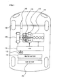
- the vehicle is equipped with an engine 100, a first MG (Motor Generator) 110, a second MG 120, a power split device 130, a reduction gear 140, a master battery 150, and a sub battery 152.
- MG Motor Generator
- ECU 170 Electronic Control Unit 170
- Engine 100, first MG 110, second MG 120, master battery 150, and sub battery 152 are controlled by an ECU (Electronic Control Unit) 170.
- ECU 170 may be split into a plurality of ECUs.
- This vehicle travels by a driving force from at least either one of engine 100 and second MG 120. More specifically, the plug-in hybrid vehicle travels while switching a HV travel mode and an EV travel mode automatically or manually.
- the vehicle travels while automatically switching at least either one or both of engine 100 and second MG 120 as a driving source depending on the operating state.
- the vehicle travels using only second MG 120 as a driving source.
- engine 100 may operate for electric power generation and the like.
- Engine 100, first MG 110, and second MG 120 are connected via power split device 130.
- the power generated by engine 100 is split into two routes by power split device 130.
- One route drives front wheels 160 via reduction gear 140.
- the other route drives first MG 110 to generate electric power.
- First MG 110 is a three-phase AC rotating electric machine having a U-phase coil, a V-phase coil, and a W-phase coil.
- First MG 110 generates electric power by the power of engine 100 split by power split device 130.
- the electric power generated by first MG 110 is appropriately used depending on the travel state of the vehicle, and states of SOCs of master battery 150 and sub battery 152. For example, during normal traveling, the electric power generated by first MG 110 directly drives second MG 120.
- the SOC of master battery 150 or sub battery 152 is lower than a predetermined value, the electric power generated by first MG 110 is converted from alternating current to direct current by an inverter as will be described later. Then it is stored in master battery 150 or sub battery 152 after adjustment of voltage by a converter as will be described later.
- first MG 110 When first MG 110 operates as a generator, first MG 110 generates a negative torque.
- the negative torque refers to such a torque that will be a load on engine 100.
- first MG 110 When first MG 110 operates as a motor while it is supplied with electric power, first MG 110 generates a positive torque.
- the positive torque refers to such a torque that will not be a load on engine 100, namely, a torque that assists rotation of engine 100. The same also applies to second MG 120.
- Second MG 120 is a three-phase AC rotating electric machine having a U-phase coil, a V-phase coil, and a W-phase coil. Second MG 120 is driven by the electric power of at least either of electric power stored in master battery 150 and sub battery 152 and the electric power generated by first MG 110.
- the driving force of second MG 120 is transmitted to front wheels 160 via reduction gear 140.
- second MG 120 assists engine 100 and makes the vehicle travel by the driving force from second MG 120.
- rear wheels may be driven.
- second MG 120 is driven by front wheels 160 via reduction gear 140, and second MG 120 operates as a generator. As a result, second MG 120 operates as a regenerative brake that converts the breaking energy to the electric power.
- the electric power generated by second MG 120 is stored in master battery 150 or sub battery 152.
- Power split device 130 is implemented by a planetary gear including a sun gear, a pinion gear, a carrier, and a ring gear.
- the pinion gear meshes with the sun gear and the ring gear.
- the carrier supports the pinion gear to be able to rotate.
- the sun gear is connected to a rotation axis of first MG 110.
- the carrier is connected to a crank shaft of engine 100.
- the ring gear is connected to a rotation axis of second MG 120 and reduction gear 140.
- master battery 150 and sub battery 152 are realized by an assembled battery formed by serially connecting a plurality of battery modules each including integrated plural battery cells. Voltages of master battery 150 and sub battery 152 are, for example, about 200V. Master battery 150 and sub battery 152 are charged with electric power supplied from a electric power source external to the vehicle, as well as from first MG 110 and second MG 120.
- Capacities of master battery 150 and sub battery 152 are identical or substantially identical.
- the plug-in hybrid vehicle in the present embodiment is further equipped with a navigation device 172.
- Navigation device 172 has a function of predicting the arrival time to the destination inputted by an operator base on, for example, the current position of the plug-in hybrid vehicle, the vehicle speed, and map data including a distance.
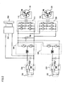
- the plug-in hybrid vehicle is provided with a master converter 200, a sub converter 202, a first inverter 210, a second inverter 220, a master SMR (System Main Relay) 230, a sub SMR 232, a charger 240, and an inlet 250.
- a master converter 200 a sub converter 202
- a first inverter 210 a second inverter 220
- a master SMR (System Main Relay) 230 a sub SMR 232
- charger 240 a charger 240
- Master converter 200 and sub converter 202 include a reactor, two npn transistors, and two diodes.
- the reactor is connected at its one end with a positive electrode side of each battery and connected at its other end with a connection point between the two npn transistors.
- the two npn transistors are connected in series.
- the npn transistor is controlled by ECU 170.
- a diode is connected between a collector and an emitter of each npn transistor so that the current flows from the emitter side to the collector side.
- npn transistor for example, IGBT (Insulated Gate Bipolar Transistor) may be used.
- a power switching device such as power MOSFET (Metal Oxide Semiconductor Field-Effect Transistor) may be used.
- sub converter 202 when the electric power discharged from sub battery 152 is supplied to first MG 110 or second MG 120, the voltage is boosted by sub converter 202. Contrarily, when sub battery 152 is charged with the electric power generated by first MG 110 or second MG 120, the voltage is decreased by sub converter 202.
- a system voltage VH between each converter and each inverter is detected by a voltage sensor 180.
- a detection result of voltage sensor 180 is transmitted to ECU 170.
- First inverter 210 includes a U-phase arm, a V-phase arm, and a W-phase arm.
- the U-phase arm, the V-phase arm, and the W-phase arm are connected in parallel.
- Each of the U-phase arm, the V-phase arm, and the W-phase arm has two npn transistors that are connected in series. Between a collector and an emitter of each npn transistor, a diode for making a current flow from the emitter side to the collector side is connected.
- a connection point of each npn transistor in each arm is connected to an end part different from a neutral point 112 of each coil of first MG 110.
- First inverter 210 converts a direct current supplied from master battery 150 or sub battery 152 to an alternating current and supplies it to first MG 110. First inverter 210 converts an alternating current generated by first MG 110 to a direct current.
- Second inverter 220 includes a U-phase arm, a V-phase arm, and a W-phase arm.
- the U-phase arm, the V-phase arm, and the W-phase arm are connected in parallel.
- Each of the U-phase arm, the V-phase arm, and the W-phase arm has two npn transistors that are connected in series. Between a collector and an emitter of each npn transistor, a diode for making a current flow from the emitter side to the collector side is connected.
- a connection point of each npn transistor in each arm is connected to an end part different from a neutral point 122 of each coil of second MG 120.
- Second inverter 220 converts a direct current supplied from master battery 150 or sub battery 152 to an alternating current, and supplies it to second MG 120. Second inverter 220 converts an alternating current generated by second MG 120 to a direct current.
- Master converter 200, sub converter 202, first inverter 210, and second inverter 220 are controlled by ECU 170.
- Master SMR 230 is provided between master battery 150 and charger 240. Master SMR 230 is a relay for switching the connected state and the disconnected state between master battery 150 and the electric system. When master SMR 230 is in an opened state, master battery 150 is disconnected from the electric system. When master SMR 230 is in a closed state, master battery 150 is connected to the electric system.
- master SMR 230 when master SMR 230 is in the opened state, master battery 150 is electrically disconnected from master converter 200, charger 240 and the like.
- master SMR 230 When master SMR 230 is in the closed state, master battery 150 is electrically connected with master converter 200, charger 240 and the like.
- Sub SMR 232 is provided between sub battery 152 and sub converter 202.
- Sub SMR 232 is a relay for switching a connected state and a disconnected state between sub battery 152 and the electric system.
- When sub SMR 232 is in an opened state sub battery 152 is disconnected from the electric system.
- When sub SMR 232 is in a closed state sub battery 152 is connected to the electric system.
- sub SMR 232 when sub SMR 232 is in the opened state, sub battery 152 is electrically disconnected from sub converter 202, charger 240 and the like.
- sub SMR 232 When sub SMR 232 is in the closed state, sub battery 152 is electrically connected with sub converter 202, charger 240 and the like.
- States of master SMR 230 and sub SMR 232 are controlled by ECU 170. For example, when ECU 170 starts up, master SMR 230 and sub SMR 232 are closed. When ECU 170 stops, master SMR 230 and sub SMR 232 are opened.
- Charger 240 is connected between master battery 150 and master converter 200. As shown in Fig. 3 , charger 240 includes an AC/DC converter circuit 242, a DC/AC converter circuit 244, an insulation transformer 246, and a rectifier circuit 248.
- AC/DC converter circuit 242 is implemented by a single-phase bridge circuit.
- AC/DC converter circuit 242 converts AC electric power to DC electric power based on a driving signal from ECU 170.
- AC/DC converter circuit 242 also functions as a boost chopper circuit that boosts the voltage by using a coil as a reactor.
- DC/AC converter circuit 244 is implemented by a single-phase bridge circuit. DC/AC converter circuit 244 converts DC electric power to high frequency AC electric power based on a driving signal from ECU 170 and outputs it to insulation transformer 246.
- Insulation transformer 246 includes a core formed of a magnetic material, and a primary coil and a secondary coil wound around the core. The primary coil and the secondary coil are electrically insulated, and are connected to DC/AC converter circuit 244 and rectifier circuit 248, respectively. Insulation transformer 246 converts the high frequency AC electric power received from DC/AC converter circuit 244 to a voltage level corresponding to a winding number ratio between the primary coil and the secondary coil, and outputs it to rectifier circuit 248. Rectifier circuit 248 rectifies AC electric power outputted from insulation transformer 246 to DC electric power.
- a voltage across AC/DC converter circuit 242 and DC/AC converter circuit 244 (terminal-to-terminal voltage of smoothing capacitor) is detected by voltage sensor 182, and a signal representing the detection result is inputted to ECU 170.
- An output current of charger 240 is detected by a current sensor 184, and a signal representing the detection result is inputted to ECU 170.
- temperature of charger 240 is detected by a temperature sensor 186, and a signal representing the detection result is inputted to ECU 170.
- ECU 170 generates a driving signal for driving charger 240 and outputs it to charger 240 when master battery 150 or sub battery 152 is charged from a electric power source external to the vehicle.
- ECU 170 has a function of detecting a fail of charger 240, as well as a function of controlling charger 240.
- a fail of charger 240 is detected.
- Inlet 250 is provided, for example, in a lateral part of the plug-in hybrid vehicle. To inlet 250, a connector 310 of a charging cable 300 that connects the plug-in hybrid vehicle and an external electric power source 402 is connected.
- Charging cable 300 that connects the plug-in hybrid vehicle and external electric power source 402 includes connector 310, a plug 320, and a CCID (Charging Circuit Interrupt Device) 330.
- CCID Charging Circuit Interrupt Device
- Connector 310 of charging cable 300 is connected to inlet 250 provided in the plug-in hybrid vehicle.
- Connector 310 is provided with a switch 312.
- switch 312 When switch 312 is closed in the condition that connector 310 of charging cable 300 is connected to inlet 250 provided in the plug-in hybrid vehicle, a connector signal CNCT indicating that connector 310 of charging cable 300 is being connected with inlet 250 provided in the plug-in hybrid vehicle is inputted to ECU 170.
- Switch 312 opens/closes in cooperation with a latch that latches connector 310 of charging cable 300 to inlet 250 of the hybrid vehicle.
- the latch oscillates as an operator presses a button provided in connector 310.
- switch 312 closes.
- latch 316 and inlet 250 are released from engagement, and switch 312 opens.
- the method for opening or closing switch 312 is not limited to this.
- plug 320 of charging cable 300 is connected to a socket 400 provided in a house.
- Socket 400 is supplied with AC electric power from external electric power source 402 of the plug-in hybrid vehicle.
- CCID 330 has a relay 332 and a control pilot circuit 334.
- relay 332 In the state that relay 332 is open, the route for supplying electric power from external electric power source 402 of the plug-in hybrid vehicle to the plug-in hybrid vehicle is blocked.
- relay 332 In the state that relay 332 is closed, electric power supply from external electric power source 402 of the plug-in hybrid vehicle to the plug-in hybrid vehicle is allowed.
- the state of relay 332 is controlled by ECU 170 in the condition that connector 310 of charging cable 300 is connected to inlet 250 of the plug-in hybrid vehicle.
- Control pilot circuit 334 sends a pilot signal (square wave signal) CPLT to a control pilot line in the condition that plug 320 of charging cable 300 is connected to socket 400, namely to external electric power source 402, and connector 310 is connected to inlet 250 provided in the plug-in hybrid vehicle.
- the pilot signal is oscillated by an oscillator provided in control pilot circuit 334.
- Control pilot circuit 334 is able to output a constant pilot signal CPLT when plug 320 of charging cable 300 is connected to socket 400 even if connector 310 is removed from inlet 250 provided in the plug-in hybrid vehicle.
- ECU 170 is unable to detect a pilot signal CPLT outputted in the condition that connector 310 is removed from inlet 250 provided in the plug-in hybrid vehicle.
- control pilot circuit 334 oscillates a pilot signal CPLT having a predetermined pulse width (duty cycle).
- the plug-in hybrid vehicle is notified of a current capacity that can be supplied by a pulse width of pilot signal CPLT.
- the plug-in hybrid vehicle is notified of a current capacity of charging cable 300.
- the pulse width of pilot signal CPLT is constant irrespective of the voltage and the current of external electric power source 402.
- the pulse width of pilot signal CPLT can vary with the kind of the charging cable that is used. To be more specific, the pulse width of pilot signal CPLT can be determined for each kind of charging cable.
- master battery 150 or sub battery 152 is charged with the electric power supplied from external electric power source 402.
- relay 332 in master SMR 230, sub SMR 232, and CCID 330 is closed.
- An AC voltage VAC of external electric power source 402 is detected by a voltage sensor 188 provided inside the plug-in hybrid vehicle.
- the detected voltage VAC is transmitted to ECU 170.
- ECU 170 a function of ECU 170 will be further described.
- the function described below may be implemented by software, or by hardware.
- ECU 170 has a first control unit 500, a setting unit 510, a second control unit 520, and a third control unit 530.
- First control unit 500 controls the SOCs of master battery 150 and sub battery 152 so that the SOC varies within the range from a predetermined upper limit value and lower limit value in the HV travel mode as shown in Fig. 6 .
- the SOCs of master battery 150 and sub battery 152 are indirectly controlled by controlling engine 100, first MG 110, and second MG 120.
- Fig. 6 shows an upper limit value and a lower limit value of SOC in a normal mode.
- the control may be conducted such that the SOCs of master battery 150 and sub battery 152 are equal to predetermined target values.
- setting unit 510 includes a first setting unit 511 and a second setting unit 512.
- First setting unit 511 sets an upper limit value and a lower limit value of SOC of master battery 150 for an EV priority mode when the condition that execution of charging with the electric power supplied from the source external to the plug-in hybrid vehicle is predicted is satisfied.
- the EV priority mode means a mode capable of executing travel in the EV travel mode preferentially.
- the upper limit value and the lower limit value of the SOC of master battery 150 are set to be higher than those in the normal mode as shown in Fig. 7 .
- the upper limit value and the lower limit value of the SOC of master battery 150 are set so that the SOC of master battery 150 is higher than the SOC of the case where the condition is not satisfied.
- the condition that execution of charging with the electric power supplied from the source external to the plug-in hybrid vehicle is predicted is, for example, a condition that time at which the plug-in hybrid vehicle is predicted to arrive at the location (for example, home) where it is defined that charging with the electric power supplied from the source external to the plug-in hybrid vehicle is possible is included in a time zone where the electric power rate is set to be lower than that in other time zones.
- the setting is made so that the upper limit value and the lower limit value of the SOC of master battery 150 are high.
- other condition than the aforementioned condition such as a condition that the expected arrival time is in the night may be employed.
- Either one of the upper limit value and the lower limit value may be set to be high. Also the setting may be made so that the upper limit value and the lower limit value are identical between the case where the condition is satisfied and the case where the condition is not satisfied. Further, the setting may be made so that the target value of the SOC of master battery 150 is high when the condition is satisfied, or the setting may be made so that the target values are identical between the case where the condition is satisfied and the case where the condition is not satisfied.
- Second setting unit 512 sets a lower limit value of the SOC of sub battery 152 for EV priority mode so that the SOC of sub battery 152 is low when the condition that execution of charging with the electric power supplied from the source external to the plug-in hybrid vehicle is predicted is satisfied.
- the setting is made so that the lower limit value of the SOC of sub battery 152 is lower than that in the normal mode as shown in Fig. 8 . That is, when the condition that execution of charging with the electric power supplied from the source external to the plug-in hybrid vehicle is predicted is satisfied, the lower limit value of the SOC of sub battery 152 is made low so that the SOC of sub battery 152 is lower than the SOC of the case where the condition is not satisfied. As a result, it is possible to make the SOC of sub battery 152 in the EV priority mode lower than the SOC in the normal mode.
- the setting may be made so that only the upper limit value is low, or both the upper limit value and the lower limit value are low. Also the setting may be made so that the target value of the SOC of master battery 150 is low when the condition is satisfied.
- the SOC of sub battery 152 becomes lower than the SOC of master battery 150 by causing the SOC of master battery 150 to be higher than the SOC of the case where the condition is not satisfied and the SOC of sub battery 152 to be lower than the SOC of the case where the condition is not satisfied.
- setting unit 510 sets the upper limit values and the lower limit values of the SOC of master battery 150 and the SOC of sub battery 152 so that the SOC of sub battery 152 is lower than the SOC of master battery 150 as shown in Fig. 9 , by causing the SOC of master battery 150 to be higher than the SOC of the case where the condition is not satisfied and the SOC of sub battery 152 to be lower than the SOC of the case where the condition is not satisfied.
- the target values of the SOC of master battery 150 and the SOC of sub battery 152 may be set so that the SOC of sub battery 152 is lower than the SOC of master battery 150.
- Second control unit 520 controls the SOC of sub battery 152 in the HV travel mode to decrease to the lower limit value as shown in Fig. 8 and Fig. 9 when the condition that execution of charging with the electric power supplied from the source external to the plug-in hybrid vehicle is predicted is satisfied.
- the plug-in hybrid vehicle travels preferentially in the EV travel mode until the SOC of sub battery 152 decreases to the lower limit value as shown in Fig. 8 and Fig. 9 .
- Third control unit 530 controls the vehicle to travel in the HV travel mode after the SOC of sub battery 152 becomes lower than the SOC of master battery 150, namely, after the SOC of sub battery 152 decreases to the lower limit value, as shown in Fig. 8 and Fig. 9 .
- step (hereinafter, step is abbreviated as S) 100 ECU 170 predicts the time at which the plug-in hybrid vehicle arrives at the location (for example, home) where it is defined that charging with the electric power supplied from the source external to the plug-in hybrid vehicle is possible.
- ECU 170 determines whether time at which the plug-in hybrid vehicle arrives at the location where it is defined that charging with the electric power supplied from the source external to the plug-in hybrid vehicle is possible is included in a time zone where electric power rate is set lower than that in other time zones.
- ECU 170 sets upper limit values and lower limit values of the SOC of master battery 150 and sub battery 152 in the normal mode.
- ECU 170 controls the SOCs of master battery 150 and sub battery 152 so that the SOCs vary within the range between the defined upper limit value and lower limit value.
- ECU 170 sets the upper limit value and the lower limit value of the SOC of master battery 150 for the EV priority mode so that they are higher than those in the normal mode.
- ECU 170 sets the lower limit value of the SOC of sub battery 152 for the EV priority mode so that it is lower than that in the normal mode.
- ECU 170 controls the SOC of master battery 150 so that the SOC varies within the range between the defined upper limit value and lower limit value, and controls the SOC of sub battery 152 so that it decreases to the lower limit value.
- ECU 170 controls the vehicle to travel in the HV travel mode.
- the time at which the plug-in hybrid vehicle arrives at the location (for example, home) where it is defined that charging with the electric power supplied from the source external to the plug-in hybrid vehicle is possible is predicted by using the navigation device (S100).
- the upper limit values and the lower limit values of the SOCs of master battery 150 and sub battery 152 in the normal mode are set (S104).
- the SOCs master battery 150 and sub battery 152 are controlled so that the SOCs vary within the range between the defined upper limit value and lower limit value (S106).
- the upper limit value and the lower limit value of the SOC of master battery 150 are set to be higher than those in the normal mode (S108).
- the lower limit value of the SOC of sub battery 152 is set to be lower than that in the normal mode (S 110).
- the SOC of master battery 150 is controlled so that the SOC varies within the range between the defined upper limit value and lower limit value and the SOC of sub battery 152 is controlled so that it decreases to the lower limit value (S 112). Then the vehicle is controlled so that it travels in the HV travel mode (S 114).
- 100 engine 110 first MG, 120 second MG, 130 power split device, 140 reduction gear, 150 master battery, 152 sub battery, 160 front wheel, 170 ECU, 172 navigation device, 200 master converter, 202 sub converter, 210 first inverter, 220 second inverter, 230 master SMR, 232 sub SMR, 240 charger, 242 AC/DC converter circuit, 244 DC/AC converter circuit, 246 insulation transformer, 248 rectifier circuit, 250 inlet, 300 charging cable, 310 connector, 312 switch, 314 button, 316 latch, 320 plug, 332 relay, 334 control pilot circuit, 400 socket, 402 electric power supply, 500 first control unit, 511 first setting unit, 512 second setting unit, 520 second control unit, 530 third control unit.
Landscapes
- Engineering & Computer Science (AREA)
- Mechanical Engineering (AREA)
- Transportation (AREA)
- Combustion & Propulsion (AREA)
- Chemical & Material Sciences (AREA)
- Power Engineering (AREA)
- Sustainable Energy (AREA)
- Life Sciences & Earth Sciences (AREA)
- Sustainable Development (AREA)
- Automation & Control Theory (AREA)
- Electric Propulsion And Braking For Vehicles (AREA)
- Hybrid Electric Vehicles (AREA)
- Control Of Vehicle Engines Or Engines For Specific Uses (AREA)
Claims (7)
- Fahrzeug, umfassend:einen Verbrennungsmotor (100) als eine Antriebsquelle,eine elektrische Drehstrommaschine (120), als eine Antriebsquelle,einen Generator (110) zum Erzeugen elektrischer Energie aus einer Antriebskraft des Verbrennungsmotors (100),einen ersten Akkumulator (150) zum Speichern elektrischer Energie, die von einer Quelle außerhalb eines Fahrzeugs geliefert wird, und elektrischer Energie, die von dem Generator (110) erzeugt wird, und zum Liefern der gespeicherten elektrischen Energie zu der elektrischen Drehstrommaschine (120),einen zweiten Akkumulator (152), der mit dem ersten Akkumulator (150) parallel geschaltet ist, zum Speichern elektrischer Energie, die von der Quelle außerhalb des Fahrzeugs und elektrischer Energie, die von dem Generator (110) erzeugt wird, und zum Liefern der gespeicherten elektrischen Energie zu der elektrischen Drehstrommaschine (120), undeine Steuereinheit (170), wobeidie Steuereinheit (170)einen Ladezustand jedes der Akkumulatoren (150, 152) gemäß einem Zielbereich und/oder einem Zielwert des Ladezustands jedes der Akkumulatoren (150, 152) steuert,den Zielbereich und/oder den Zielwert des Ladezustands jedes der Akkumulatoren (150, 152) derart einstellt, dass der Ladezustand des zweiten Akkumulators (152) niedriger ist als der Ladezustand des ersten Akkumulators (150) indem, wenn eine Bedingung, dass die Ausführung des Ladens mit elektrischer Energie, die von der Quelle außerhalb des Fahrzeugs geliefert wird, vorhergesagt ist, erfüllt ist, veranlasst wird, dass der Ladezustand des ersten Akkumulators (150) gleich oder größer ist als der Ladezustand des ersten Akkumulators (150) in dem Fall, in dem die Bedingung nicht erfüllt ist, und der Ladezustand des zweiten Akkumulators (152) niedriger ist als der Ladezustand des zweiten Akkumulators (152) in dem Fall, in dem die Bedingung nicht erfüllt ist, undden Verbrennungsmotor (100) und die elektrische Drehstrommaschine (120) derart steuert, dass das Fahrzeug durch eine Antriebskraft des Verbrennungsmotors (100) und/oder der elektrischen Drehstrommaschine (120) fährt, nachdem der Ladezustand des zweiten Akkumulators (152) niedriger geworden ist als der Ladezustand des ersten Akkumulators (150).
- Fahrzeug nach Anspruch 1, wobei
die Bedingung, dass das Ausführen des Ladens mit elektrischer Energie, die von der Quelle außerhalb des Fahrzeugs geliefert wird, vorhergesagt wird, eine Bedingung ist, dass die Zeit, bei der das Ankommen des Fahrzeugs an einem Ort vorhergesagt ist, an dem definiert ist, dass das Laden mit elektrischer Energie, die von der Quelle außerhalb des Fahrzeugs geliefert wird, möglich ist, in einer Zeitzone, in der die elektrische Energierate eingestellt ist, um niedriger zu sein als in den anderen Zeitzonen, enthalten ist. - Fahrzeug nach Anspruch 1, wobei
die Steuereinheit (170) den Ladezustand des zweiten Akkumulators (152) steuert, um auf einen niedrigeren Grenzwert zu sinken. - Steuerverfahren für ein Fahrzeug, das mit einem Verbrennungsmotor (100) als einer Antriebsquelle, einer elektrischen Drehstrommaschine (120) als einer Antriebsquelle, einem Generator (110) zum Erzeugen elektrischer Energie durch eine Antriebskraft des Verbrennungsmotors (100), einem ersten Akkumulator (150) zum Speichern elektrischer Energie, die von einer Quelle außerhalb eines Fahrzeugs geliefert wird, und elektrischer Energie, die von dem Generator (110) erzeugt wird, und zum Liefern der gespeicherten elektrischen Energie zu der elektrischen Drehstrommaschine (120), und einem zweiten Akkumulator (152), der mit dem ersten Akkumulator (150) parallel geschaltet ist, zum Speichern elektrischer Energie, die von der Quelle außerhalb des Fahrzeugs und der elektrischen Energie, die von dem Generator (110) erzeugt wird, und zum Liefern der gespeicherten elektrischen Energie zu der elektrischen Drehstrommaschine (120), ausgestattet ist, wobei das Verfahren die folgenden Schritte aufweist:Steuern eines Ladezustands der Akkumulatoren (150, 152) gemäß einem Zielbereich und/oder einem Zielwert des Ladezustands jedes der Akkumulatoren (150, 152),Einstellen des Zielbereichs und/oder des Zielwerts eines Ladezustand der zwei Akkumulatoren (150, 152) derart, dass der Ladezustand des zweiten Akkumulators (152) niedriger ist als der Ladezustand des ersten Akkumulators (150) indem, wenn eine Bedingung, dass die Ausführung des Aufladens mit elektrischer Energie, die von der Quelle außerhalb des Fahrzeugs geliefert wird, vorhergesagt ist, erfüllt ist, veranlasst wird, dass der Ladezustand des ersten Akkumulators (150) gleich oder größer ist als der Ladezustand des ersten Akkumulators (150) in dem Fall, in dem die Bedingung nicht erfüllt ist, und der Ladezustand des zweiten Akkumulators (152) niedriger ist als der Ladezustand des zweiten Akkumulators (152) in dem Fall, in dem die Bedingung nicht erfüllt ist, undSteuern des Verbrennungsmotors (100) und der elektrischen Drehstrommaschine (120) derart, dass das Fahrzeug durch eine Antriebskraft des Verbrennungsmotors (100) und/oder der elektrischen Drehstrommaschine (120) gefahren wird, nachdem der Ladezustand des zweiten Akkumulators (152) niedriger geworden ist als der Ladezustand des ersten Akkumulators (150).
- Steuerverfahren für ein Fahrzeug nach Anspruch 4, wobei
die Bedingung, dass die Ausführung des Ladens mit der elektrischen Energie, die von der Quelle außerhalb des Fahrzeugs geliefert wird, vorhergesagt ist, eine Bedingung ist, dass die Zeit, bei der die Ankunft des Fahrzeugs an einem Ort vorhergesagt ist, an dem definiert ist, dass das Laden mit elektrischer Energie, die von der Quelle außerhalb des Fahrzeugs geliefert wird, möglich ist, in einer Zeitzone, in der die elektrische Energierate eingestellt ist, um niedriger zu sein als in anderen Zeitzonen, enthalten ist. - Steuerverfahren für ein Fahrzeug nach Anspruch 4, das ferner
den Schritt des Steuerns des Ladezustands des zweiten Akkumulators (152) zum Sinken auf einen niedrigeren Grenzwert aufweist. - Steuervorrichtung für ein Fahrzeug, das mit einem Verbrennungsmotor (100) als einer Antriebsquelle, einer elektrischen Drehstrommaschine (120) als einer Antriebsquelle, einem Generator (110) zum Erzeugen elektrischer Energie durch eine Antriebskraft des Verbrennungsmotors (100), einem ersten Akkumulator (150) zum Speichern elektrischer Energie, die von einer Quelle außerhalb eines Fahrzeugs geliefert wird und elektrischer Energie, die von dem Generator (110) erzeugt wird, und zum Liefern der elektrischen Energie zu der elektrischen Drehstrommaschine (120), und einem zweiten Akkumulator (152), der mit dem ersten Akkumulator (150) parallel geschaltet ist, zum Speichern elektrischer Energie, die von der Quelle außerhalb des Fahrzeugs geliefert wird und elektrischer Energie, die von dem Generator (110) geliefert wird, und zum Liefern der gespeicherten elektrischen Energie zu der elektrischen Drehstrommaschine (120) ausgestattet ist, wobei die Steuervorrichtung für ein Fahrzeug Folgendes aufweist:Mittel (500) zum Steuern eines Ladezustands der Akkumulatoren (150, 152) gemäß einem Zielbereich und/oder einem Zielwert des Ladezustands jedes der Akkumulatoren (150, 152),Mittel (510) zum Einstellen des Zielbereichs und/oder des Zielwerts des Ladezustands jedes der Akkumulatoren (150, 152) derart, dass der Ladezustand der zweiten Batterie (152) niedriger ist als ein Ladezustand der ersten Batterie (150), indem, wenn eine Bedingung, dass die Ausführung des Ladens mit elektrischer Energie, die von der Quelle außerhalb des Fahrzeugs geliefert wird, vorhergesagt ist, erfüllt ist, veranlasst wird, dass der Ladezustand des ersten Akkumulators (150) gleich oder größer ist als der Ladezustand des ersten Akkumulators (150) in dem Fall, in dem die Bedingung nicht erfüllt ist, und der Ladezustand des zweiten Akkumulators (152) niedriger ist als der Ladezustand des zweiten Akkumulators (152) in dem Fall, in dem die Bedingung nicht erfüllt ist, undMittel (530) zum Steuern des Verbrennungsmotors (100) und der elektrischen Drehstrommaschine (120) derart, dass das Fahrzeug durch eine Antriebskraft des Verbrennungsmotors (100) und/oder der elektrischen Drehstrommaschine (120) gefahren wird, nachdem der Ladezustand des zweiten Akkumulators (152) niedriger geworden ist als der Ladezustand des ersten Akkumulators (150).
Applications Claiming Priority (2)
| Application Number | Priority Date | Filing Date | Title |
|---|---|---|---|
| JP2008226009A JP4466772B2 (ja) | 2008-09-03 | 2008-09-03 | 車両の制御装置 |
| PCT/JP2009/058899 WO2010026801A1 (ja) | 2008-09-03 | 2009-05-13 | 車両、車両の制御方法および制御装置 |
Publications (3)
| Publication Number | Publication Date |
|---|---|
| EP2332798A1 EP2332798A1 (de) | 2011-06-15 |
| EP2332798A4 EP2332798A4 (de) | 2013-03-13 |
| EP2332798B1 true EP2332798B1 (de) | 2014-08-27 |
Family
ID=41796976
Family Applications (1)
| Application Number | Title | Priority Date | Filing Date |
|---|---|---|---|
| EP09811330.1A Not-in-force EP2332798B1 (de) | 2008-09-03 | 2009-05-13 | Fahrzeug, fahrzeugsteuerungsverfahren und steuervorrichtung |
Country Status (5)
| Country | Link |
|---|---|
| US (1) | US8469857B2 (de) |
| EP (1) | EP2332798B1 (de) |
| JP (1) | JP4466772B2 (de) |
| CN (1) | CN102143873B (de) |
| WO (1) | WO2010026801A1 (de) |
Families Citing this family (38)
| Publication number | Priority date | Publication date | Assignee | Title |
|---|---|---|---|---|
| JP4179351B2 (ja) * | 2006-07-07 | 2008-11-12 | トヨタ自動車株式会社 | 電源システムおよびそれを備えた車両、電源システムの制御方法、ならびに電源システムの制御をコンピュータに実行させるためのプログラムを記録したコンピュータ読取可能な記録媒体 |
| JP5184718B2 (ja) * | 2010-07-28 | 2013-04-17 | パナソニック株式会社 | 電力供給システム、電力供給システムの制御装置、電力供給システムの運転方法、及び電力供給システムの制御方法 |
| TWI413340B (zh) * | 2010-11-17 | 2013-10-21 | 財團法人工業技術研究院 | 延長插電式混合動力車電池壽命之裝置與方法 |
| US9090174B2 (en) * | 2010-12-17 | 2015-07-28 | Panasonic intellectual property Management co., Ltd | Power supply device and power supply method |
| JP5605436B2 (ja) * | 2010-12-20 | 2014-10-15 | トヨタ自動車株式会社 | 電動車両およびその制御方法 |
| JP5747988B2 (ja) * | 2011-08-25 | 2015-07-15 | トヨタ自動車株式会社 | 車両、および、車両の制御方法ならびに制御装置 |
| EP2570284B1 (de) * | 2011-09-14 | 2016-10-26 | V2 Plug-in Hybrid Vehicle Partnership Handelsbolag | Steckdosenelektrohybridfahrzeug |
| US8838385B2 (en) * | 2011-12-20 | 2014-09-16 | Ford Global Technologies, Llc | Method and apparatus for vehicle routing |
| JP2013146129A (ja) * | 2012-01-13 | 2013-07-25 | Iyo Matsuyama Hitech Kk | 蓄発電システム |
| WO2013154093A1 (ja) * | 2012-04-09 | 2013-10-17 | 日産自動車株式会社 | ハイブリッド車両の制御装置、ハイブリッド車両の管理システム、及びハイブリッド車両の管理方法 |
| WO2013168491A1 (ja) * | 2012-05-11 | 2013-11-14 | 富士電機株式会社 | モータ駆動装置 |
| DE112012006375T5 (de) * | 2012-05-15 | 2015-02-19 | Toyota Jidosha Kabushiki Kaisha | Fahrzeugfahrtsteuerungsunterstützungsvorrichtung |
| US9441599B2 (en) | 2012-07-17 | 2016-09-13 | Altigreen Propulsion Labs Private Limited | Induction motor-permanent magnet generator tandem configuration starter-generator for hybrid vehicles |
| US9580065B2 (en) | 2012-07-17 | 2017-02-28 | Altigreen Propulsion Labs Private Limited | Dual-structured electric drive and power system for hybrid vehicles |
| GB2517470B (en) * | 2013-08-21 | 2016-07-20 | Jaguar Land Rover Ltd | Hybrid electric vehicle controller and method |
| JP5920306B2 (ja) * | 2013-10-02 | 2016-05-18 | トヨタ自動車株式会社 | ハイブリッド車両およびハイブリッド車両の制御方法 |
| FR3015411B1 (fr) * | 2013-12-19 | 2016-01-22 | Peugeot Citroen Automobiles Sa | Procede de calcul de consigne de couple pour une machine electrique couplee a un moteur thermique d'un vehicule hybride |
| KR20150121919A (ko) * | 2014-04-22 | 2015-10-30 | 현대모비스 주식회사 | 배터리 충전 장치 및 그 방법 |
| KR102263726B1 (ko) * | 2014-10-08 | 2021-06-11 | 현대모비스 주식회사 | 하이브리드 차량의 전력 공급 장치 및 방법 |
| US9649944B2 (en) * | 2015-04-21 | 2017-05-16 | Atieva, Inc. | Method of providing constant driving range in an electric vehicle |
| JP6432534B2 (ja) * | 2016-01-18 | 2018-12-05 | スズキ株式会社 | ハイブリッド車両 |
| JP2017204407A (ja) * | 2016-05-12 | 2017-11-16 | トヨタ自動車株式会社 | 燃料電池システム及びその制御方法 |
| EP3497437B1 (de) | 2016-08-15 | 2023-03-01 | Royal Melbourne Institute Of Technology | Gassensorkapsel |
| CN107782325A (zh) * | 2016-08-30 | 2018-03-09 | 中兴通讯股份有限公司 | 一种传输导航信息的方法和装置 |
| JP2018103747A (ja) * | 2016-12-26 | 2018-07-05 | スズキ株式会社 | ハイブリッド車両 |
| JP6930306B2 (ja) * | 2017-09-05 | 2021-09-01 | トヨタ自動車株式会社 | 電動車両 |
| JP6897528B2 (ja) * | 2017-12-05 | 2021-06-30 | トヨタ自動車株式会社 | ハイブリッド車両の制御装置 |
| JP7059761B2 (ja) * | 2018-04-03 | 2022-04-26 | トヨタ自動車株式会社 | 車両の充放電制御装置 |
| JP7086184B2 (ja) * | 2018-05-22 | 2022-06-17 | 本田技研工業株式会社 | 電動車両および電動車両制御方法 |
| JP7056385B2 (ja) * | 2018-05-31 | 2022-04-19 | トヨタ自動車株式会社 | 電動車両 |
| CN109435762B (zh) * | 2018-11-08 | 2022-08-05 | 南京华威智能汽车系统有限公司 | 甲醇增程式电动汽车电池管理方法、装置、设备及介质 |
| JP2020145850A (ja) * | 2019-03-06 | 2020-09-10 | トヨタ自動車株式会社 | 車両用電源システム |
| JP7143823B2 (ja) * | 2019-07-25 | 2022-09-29 | トヨタ自動車株式会社 | 車両の制御装置 |
| KR102821240B1 (ko) * | 2020-07-06 | 2025-06-18 | 현대자동차주식회사 | 차량 및 그 제어 방법 |
| CN114683826A (zh) * | 2020-12-25 | 2022-07-01 | 深圳臻宇新能源动力科技有限公司 | 混合动力车辆及其动力系统和充电控制方法 |
| JP7675669B2 (ja) * | 2022-02-03 | 2025-05-13 | 株式会社クボタ | 電動作業車 |
| JP2023122897A (ja) * | 2022-02-24 | 2023-09-05 | パナソニックIpマネジメント株式会社 | 画像合成装置 |
| JP2025064236A (ja) * | 2023-10-05 | 2025-04-17 | 株式会社Subaru | 車載バッテリの充電制御システム |
Family Cites Families (13)
| Publication number | Priority date | Publication date | Assignee | Title |
|---|---|---|---|---|
| JP3385657B2 (ja) * | 1993-08-10 | 2003-03-10 | トヨタ自動車株式会社 | 車載用ナビゲーション装置 |
| JPH08154307A (ja) * | 1994-11-29 | 1996-06-11 | Mitsubishi Motors Corp | 燃料使用制限式ハイブリッド電気自動車 |
| JP2001069612A (ja) * | 1999-08-27 | 2001-03-16 | Yamaha Motor Co Ltd | ハイブリッド駆動装置 |
| US6701880B1 (en) * | 2002-04-12 | 2004-03-09 | Ford Motor Company | Method and apparatus for starting a motor vehicle |
| JP2004178965A (ja) * | 2002-11-27 | 2004-06-24 | Nissan Motor Co Ltd | 車両の制御装置 |
| JP4281725B2 (ja) | 2005-09-01 | 2009-06-17 | トヨタ自動車株式会社 | ハイブリッド自動車 |
| JP4525613B2 (ja) * | 2006-02-28 | 2010-08-18 | トヨタ自動車株式会社 | 車両用動力伝達装置の制御装置 |
| JP4413888B2 (ja) * | 2006-06-13 | 2010-02-10 | 株式会社東芝 | 蓄電池システム、車載電源システム、車両、および蓄電池システムの充電方法 |
| JP4905300B2 (ja) * | 2006-09-28 | 2012-03-28 | トヨタ自動車株式会社 | 電源システムおよびそれを備えた車両、電源システムの制御方法ならびにその制御方法をコンピュータに実行させるためのプログラムを記録したコンピュータ読取可能な記録媒体 |
| JP2008087516A (ja) * | 2006-09-29 | 2008-04-17 | Toyota Motor Corp | ハイブリッド車両およびハイブリッド車両の走行制御方法 |
| JP4321576B2 (ja) * | 2006-10-24 | 2009-08-26 | トヨタ自動車株式会社 | 電源装置およびそれを備える車両 |
| JP4513812B2 (ja) * | 2007-01-04 | 2010-07-28 | トヨタ自動車株式会社 | 車両の電源装置および車両 |
| US8271173B2 (en) * | 2007-11-07 | 2012-09-18 | GM Global Technology Operations LLC | Method and apparatus for controlling a hybrid powertrain system |
-
2008
- 2008-09-03 JP JP2008226009A patent/JP4466772B2/ja not_active Expired - Fee Related
-
2009
- 2009-05-13 CN CN2009801343167A patent/CN102143873B/zh not_active Expired - Fee Related
- 2009-05-13 WO PCT/JP2009/058899 patent/WO2010026801A1/ja not_active Ceased
- 2009-05-13 EP EP09811330.1A patent/EP2332798B1/de not_active Not-in-force
- 2009-05-13 US US13/061,610 patent/US8469857B2/en not_active Expired - Fee Related
Also Published As
| Publication number | Publication date |
|---|---|
| EP2332798A4 (de) | 2013-03-13 |
| CN102143873B (zh) | 2013-11-13 |
| EP2332798A1 (de) | 2011-06-15 |
| JP4466772B2 (ja) | 2010-05-26 |
| JP2010058640A (ja) | 2010-03-18 |
| US8469857B2 (en) | 2013-06-25 |
| WO2010026801A1 (ja) | 2010-03-11 |
| US20110160019A1 (en) | 2011-06-30 |
| CN102143873A (zh) | 2011-08-03 |
Similar Documents
| Publication | Publication Date | Title |
|---|---|---|
| EP2332798B1 (de) | Fahrzeug, fahrzeugsteuerungsverfahren und steuervorrichtung | |
| US8186465B2 (en) | Hybrid vehicle and controlling method thereof | |
| KR101036040B1 (ko) | 하이브리드 차량 | |
| US8538616B2 (en) | Power supply system for electrically powered vehicle, electrically powered vehicle, and method for controlling the same | |
| US8659182B2 (en) | Power supply system and electric powered vehicle including power supply system, and method for controlling power supply system | |
| US8952564B2 (en) | Power source system for electric powered vehicle | |
| US8681457B2 (en) | Power source system for electric powered vehicle and control method therefor | |
| CN102458907B (zh) | 电动车辆的电源系统及其控制方法 | |
| JP5716694B2 (ja) | 電動車両 | |
| EP2700529A1 (de) | Stromversorgungsvorrichtung für ein elektrisch angetriebenes fahrzeug und steuerverfahren dafür | |
| JP5104898B2 (ja) | 電気システムの電力制限装置 | |
| US20100204860A1 (en) | Control apparatus and control method for vehicle | |
| JP2010098844A (ja) | 車両の電源システム | |
| CN101682202A (zh) | 车辆的电源装置 | |
| JP5015858B2 (ja) | 電動車両の電源システムおよびその制御方法 | |
| JP2010226869A (ja) | 電動車両 | |
| JP2009278706A (ja) | 電動車両の充電装置 | |
| JP2012249455A (ja) | 車両の電気システム | |
| JP5741385B2 (ja) | バッテリの充電システム | |
| JP2010115050A (ja) | 車両の電源システム | |
| JP5621264B2 (ja) | 車両の電気システム | |
| JP2013059164A (ja) | 電動車両の電源制御装置 |
Legal Events
| Date | Code | Title | Description |
|---|---|---|---|
| PUAI | Public reference made under article 153(3) epc to a published international application that has entered the european phase |
Free format text: ORIGINAL CODE: 0009012 |
|
| 17P | Request for examination filed |
Effective date: 20110401 |
|
| AK | Designated contracting states |
Kind code of ref document: A1 Designated state(s): AT BE BG CH CY CZ DE DK EE ES FI FR GB GR HR HU IE IS IT LI LT LU LV MC MK MT NL NO PL PT RO SE SI SK TR |
|
| AX | Request for extension of the european patent |
Extension state: AL BA RS |
|
| DAX | Request for extension of the european patent (deleted) | ||
| RAP1 | Party data changed (applicant data changed or rights of an application transferred) |
Owner name: TOYOTA JIDOSHA KABUSHIKI KAISHA |
|
| A4 | Supplementary search report drawn up and despatched |
Effective date: 20130211 |
|
| RIC1 | Information provided on ipc code assigned before grant |
Ipc: F02D 29/02 20060101ALI20130205BHEP Ipc: B60K 6/445 20071001ALI20130205BHEP Ipc: B60W 10/06 20060101ALI20130205BHEP Ipc: B60W 10/26 20060101AFI20130205BHEP Ipc: B60W 10/08 20060101ALI20130205BHEP Ipc: B60W 20/00 20060101ALI20130205BHEP |
|
| GRAP | Despatch of communication of intention to grant a patent |
Free format text: ORIGINAL CODE: EPIDOSNIGR1 |
|
| INTG | Intention to grant announced |
Effective date: 20140317 |
|
| RIN1 | Information on inventor provided before grant (corrected) |
Inventor name: HARADA, HIRONORI |
|
| GRAS | Grant fee paid |
Free format text: ORIGINAL CODE: EPIDOSNIGR3 |
|
| GRAA | (expected) grant |
Free format text: ORIGINAL CODE: 0009210 |
|
| AK | Designated contracting states |
Kind code of ref document: B1 Designated state(s): AT BE BG CH CY CZ DE DK EE ES FI FR GB GR HR HU IE IS IT LI LT LU LV MC MK MT NL NO PL PT RO SE SI SK TR |
|
| REG | Reference to a national code |
Ref country code: GB Ref legal event code: FG4D |
|
| REG | Reference to a national code |
Ref country code: CH Ref legal event code: EP |
|
| REG | Reference to a national code |
Ref country code: AT Ref legal event code: REF Ref document number: 684368 Country of ref document: AT Kind code of ref document: T Effective date: 20140915 |
|
| REG | Reference to a national code |
Ref country code: IE Ref legal event code: FG4D |
|
| REG | Reference to a national code |
Ref country code: DE Ref legal event code: R096 Ref document number: 602009026337 Country of ref document: DE Effective date: 20141009 |
|
| REG | Reference to a national code |
Ref country code: AT Ref legal event code: MK05 Ref document number: 684368 Country of ref document: AT Kind code of ref document: T Effective date: 20140827 |
|
| REG | Reference to a national code |
Ref country code: LT Ref legal event code: MG4D |
|
| REG | Reference to a national code |
Ref country code: NL Ref legal event code: VDEP Effective date: 20140827 |
|
| PG25 | Lapsed in a contracting state [announced via postgrant information from national office to epo] |
Ref country code: SE Free format text: LAPSE BECAUSE OF FAILURE TO SUBMIT A TRANSLATION OF THE DESCRIPTION OR TO PAY THE FEE WITHIN THE PRESCRIBED TIME-LIMIT Effective date: 20140827 Ref country code: PT Free format text: LAPSE BECAUSE OF FAILURE TO SUBMIT A TRANSLATION OF THE DESCRIPTION OR TO PAY THE FEE WITHIN THE PRESCRIBED TIME-LIMIT Effective date: 20141229 Ref country code: BG Free format text: LAPSE BECAUSE OF FAILURE TO SUBMIT A TRANSLATION OF THE DESCRIPTION OR TO PAY THE FEE WITHIN THE PRESCRIBED TIME-LIMIT Effective date: 20141127 Ref country code: GR Free format text: LAPSE BECAUSE OF FAILURE TO SUBMIT A TRANSLATION OF THE DESCRIPTION OR TO PAY THE FEE WITHIN THE PRESCRIBED TIME-LIMIT Effective date: 20141128 Ref country code: FI Free format text: LAPSE BECAUSE OF FAILURE TO SUBMIT A TRANSLATION OF THE DESCRIPTION OR TO PAY THE FEE WITHIN THE PRESCRIBED TIME-LIMIT Effective date: 20140827 Ref country code: LT Free format text: LAPSE BECAUSE OF FAILURE TO SUBMIT A TRANSLATION OF THE DESCRIPTION OR TO PAY THE FEE WITHIN THE PRESCRIBED TIME-LIMIT Effective date: 20140827 Ref country code: ES Free format text: LAPSE BECAUSE OF FAILURE TO SUBMIT A TRANSLATION OF THE DESCRIPTION OR TO PAY THE FEE WITHIN THE PRESCRIBED TIME-LIMIT Effective date: 20140827 Ref country code: NO Free format text: LAPSE BECAUSE OF FAILURE TO SUBMIT A TRANSLATION OF THE DESCRIPTION OR TO PAY THE FEE WITHIN THE PRESCRIBED TIME-LIMIT Effective date: 20141127 |
|
| REG | Reference to a national code |
Ref country code: DE Ref legal event code: R084 Ref document number: 602009026337 Country of ref document: DE |
|
| PG25 | Lapsed in a contracting state [announced via postgrant information from national office to epo] |
Ref country code: IS Free format text: LAPSE BECAUSE OF FAILURE TO SUBMIT A TRANSLATION OF THE DESCRIPTION OR TO PAY THE FEE WITHIN THE PRESCRIBED TIME-LIMIT Effective date: 20141227 Ref country code: AT Free format text: LAPSE BECAUSE OF FAILURE TO SUBMIT A TRANSLATION OF THE DESCRIPTION OR TO PAY THE FEE WITHIN THE PRESCRIBED TIME-LIMIT Effective date: 20140827 Ref country code: CY Free format text: LAPSE BECAUSE OF FAILURE TO SUBMIT A TRANSLATION OF THE DESCRIPTION OR TO PAY THE FEE WITHIN THE PRESCRIBED TIME-LIMIT Effective date: 20140827 Ref country code: LV Free format text: LAPSE BECAUSE OF FAILURE TO SUBMIT A TRANSLATION OF THE DESCRIPTION OR TO PAY THE FEE WITHIN THE PRESCRIBED TIME-LIMIT Effective date: 20140827 Ref country code: HR Free format text: LAPSE BECAUSE OF FAILURE TO SUBMIT A TRANSLATION OF THE DESCRIPTION OR TO PAY THE FEE WITHIN THE PRESCRIBED TIME-LIMIT Effective date: 20140827 |
|
| REG | Reference to a national code |
Ref country code: GB Ref legal event code: 746 Effective date: 20150226 |
|
| PG25 | Lapsed in a contracting state [announced via postgrant information from national office to epo] |
Ref country code: NL Free format text: LAPSE BECAUSE OF FAILURE TO SUBMIT A TRANSLATION OF THE DESCRIPTION OR TO PAY THE FEE WITHIN THE PRESCRIBED TIME-LIMIT Effective date: 20140827 |
|
| REG | Reference to a national code |
Ref country code: DE Ref legal event code: R084 Ref document number: 602009026337 Country of ref document: DE Effective date: 20150223 |
|
| PG25 | Lapsed in a contracting state [announced via postgrant information from national office to epo] |
Ref country code: IT Free format text: LAPSE BECAUSE OF FAILURE TO SUBMIT A TRANSLATION OF THE DESCRIPTION OR TO PAY THE FEE WITHIN THE PRESCRIBED TIME-LIMIT Effective date: 20140827 Ref country code: DK Free format text: LAPSE BECAUSE OF FAILURE TO SUBMIT A TRANSLATION OF THE DESCRIPTION OR TO PAY THE FEE WITHIN THE PRESCRIBED TIME-LIMIT Effective date: 20140827 Ref country code: EE Free format text: LAPSE BECAUSE OF FAILURE TO SUBMIT A TRANSLATION OF THE DESCRIPTION OR TO PAY THE FEE WITHIN THE PRESCRIBED TIME-LIMIT Effective date: 20140827 Ref country code: SK Free format text: LAPSE BECAUSE OF FAILURE TO SUBMIT A TRANSLATION OF THE DESCRIPTION OR TO PAY THE FEE WITHIN THE PRESCRIBED TIME-LIMIT Effective date: 20140827 Ref country code: RO Free format text: LAPSE BECAUSE OF FAILURE TO SUBMIT A TRANSLATION OF THE DESCRIPTION OR TO PAY THE FEE WITHIN THE PRESCRIBED TIME-LIMIT Effective date: 20140827 Ref country code: CZ Free format text: LAPSE BECAUSE OF FAILURE TO SUBMIT A TRANSLATION OF THE DESCRIPTION OR TO PAY THE FEE WITHIN THE PRESCRIBED TIME-LIMIT Effective date: 20140827 |
|
| REG | Reference to a national code |
Ref country code: DE Ref legal event code: R097 Ref document number: 602009026337 Country of ref document: DE |
|
| PG25 | Lapsed in a contracting state [announced via postgrant information from national office to epo] |
Ref country code: PL Free format text: LAPSE BECAUSE OF FAILURE TO SUBMIT A TRANSLATION OF THE DESCRIPTION OR TO PAY THE FEE WITHIN THE PRESCRIBED TIME-LIMIT Effective date: 20140827 |
|
| PLBE | No opposition filed within time limit |
Free format text: ORIGINAL CODE: 0009261 |
|
| STAA | Information on the status of an ep patent application or granted ep patent |
Free format text: STATUS: NO OPPOSITION FILED WITHIN TIME LIMIT |
|
| 26N | No opposition filed |
Effective date: 20150528 |
|
| PG25 | Lapsed in a contracting state [announced via postgrant information from national office to epo] |
Ref country code: SI Free format text: LAPSE BECAUSE OF FAILURE TO SUBMIT A TRANSLATION OF THE DESCRIPTION OR TO PAY THE FEE WITHIN THE PRESCRIBED TIME-LIMIT Effective date: 20140827 |
|
| REG | Reference to a national code |
Ref country code: CH Ref legal event code: PL |
|
| PG25 | Lapsed in a contracting state [announced via postgrant information from national office to epo] |
Ref country code: CH Free format text: LAPSE BECAUSE OF NON-PAYMENT OF DUE FEES Effective date: 20150531 Ref country code: MC Free format text: LAPSE BECAUSE OF FAILURE TO SUBMIT A TRANSLATION OF THE DESCRIPTION OR TO PAY THE FEE WITHIN THE PRESCRIBED TIME-LIMIT Effective date: 20140827 Ref country code: LU Free format text: LAPSE BECAUSE OF FAILURE TO SUBMIT A TRANSLATION OF THE DESCRIPTION OR TO PAY THE FEE WITHIN THE PRESCRIBED TIME-LIMIT Effective date: 20150513 Ref country code: LI Free format text: LAPSE BECAUSE OF NON-PAYMENT OF DUE FEES Effective date: 20150531 |
|
| REG | Reference to a national code |
Ref country code: IE Ref legal event code: MM4A |
|
| REG | Reference to a national code |
Ref country code: FR Ref legal event code: PLFP Year of fee payment: 8 |
|
| PG25 | Lapsed in a contracting state [announced via postgrant information from national office to epo] |
Ref country code: IE Free format text: LAPSE BECAUSE OF NON-PAYMENT OF DUE FEES Effective date: 20150513 |
|
| PG25 | Lapsed in a contracting state [announced via postgrant information from national office to epo] |
Ref country code: BE Free format text: LAPSE BECAUSE OF FAILURE TO SUBMIT A TRANSLATION OF THE DESCRIPTION OR TO PAY THE FEE WITHIN THE PRESCRIBED TIME-LIMIT Effective date: 20140827 |
|
| PG25 | Lapsed in a contracting state [announced via postgrant information from national office to epo] |
Ref country code: MT Free format text: LAPSE BECAUSE OF FAILURE TO SUBMIT A TRANSLATION OF THE DESCRIPTION OR TO PAY THE FEE WITHIN THE PRESCRIBED TIME-LIMIT Effective date: 20140827 |
|
| REG | Reference to a national code |
Ref country code: FR Ref legal event code: PLFP Year of fee payment: 9 |
|
| PG25 | Lapsed in a contracting state [announced via postgrant information from national office to epo] |
Ref country code: HU Free format text: LAPSE BECAUSE OF FAILURE TO SUBMIT A TRANSLATION OF THE DESCRIPTION OR TO PAY THE FEE WITHIN THE PRESCRIBED TIME-LIMIT; INVALID AB INITIO Effective date: 20090513 |
|
| PG25 | Lapsed in a contracting state [announced via postgrant information from national office to epo] |
Ref country code: TR Free format text: LAPSE BECAUSE OF FAILURE TO SUBMIT A TRANSLATION OF THE DESCRIPTION OR TO PAY THE FEE WITHIN THE PRESCRIBED TIME-LIMIT Effective date: 20140827 |
|
| REG | Reference to a national code |
Ref country code: FR Ref legal event code: PLFP Year of fee payment: 10 |
|
| PGFP | Annual fee paid to national office [announced via postgrant information from national office to epo] |
Ref country code: GB Payment date: 20180329 Year of fee payment: 10 |
|
| PG25 | Lapsed in a contracting state [announced via postgrant information from national office to epo] |
Ref country code: MK Free format text: LAPSE BECAUSE OF FAILURE TO SUBMIT A TRANSLATION OF THE DESCRIPTION OR TO PAY THE FEE WITHIN THE PRESCRIBED TIME-LIMIT Effective date: 20140827 |
|
| PGFP | Annual fee paid to national office [announced via postgrant information from national office to epo] |
Ref country code: DE Payment date: 20180502 Year of fee payment: 10 |
|
| PGFP | Annual fee paid to national office [announced via postgrant information from national office to epo] |
Ref country code: FR Payment date: 20180411 Year of fee payment: 10 |
|
| RIC2 | Information provided on ipc code assigned after grant |
Ipc: B60W 20/00 20160101ALI20130205BHEP Ipc: B60W 10/26 20060101AFI20130205BHEP Ipc: B60W 10/08 20060101ALI20130205BHEP Ipc: B60K 6/445 20071001ALI20130205BHEP Ipc: F02D 29/02 20060101ALI20130205BHEP Ipc: B60W 10/06 20060101ALI20130205BHEP |
|
| REG | Reference to a national code |
Ref country code: DE Ref legal event code: R119 Ref document number: 602009026337 Country of ref document: DE |
|
| GBPC | Gb: european patent ceased through non-payment of renewal fee |
Effective date: 20190513 |
|
| PG25 | Lapsed in a contracting state [announced via postgrant information from national office to epo] |
Ref country code: GB Free format text: LAPSE BECAUSE OF NON-PAYMENT OF DUE FEES Effective date: 20190513 Ref country code: DE Free format text: LAPSE BECAUSE OF NON-PAYMENT OF DUE FEES Effective date: 20191203 |
|
| PG25 | Lapsed in a contracting state [announced via postgrant information from national office to epo] |
Ref country code: FR Free format text: LAPSE BECAUSE OF NON-PAYMENT OF DUE FEES Effective date: 20190531 |