EP2332854B1 - Structure d étanchéité pour récipient d aérosol, récipient d aérosol, et procédé de fabrication de récipient d aérosol - Google Patents
Structure d étanchéité pour récipient d aérosol, récipient d aérosol, et procédé de fabrication de récipient d aérosol Download PDFInfo
- Publication number
- EP2332854B1 EP2332854B1 EP09819243.8A EP09819243A EP2332854B1 EP 2332854 B1 EP2332854 B1 EP 2332854B1 EP 09819243 A EP09819243 A EP 09819243A EP 2332854 B1 EP2332854 B1 EP 2332854B1
- Authority
- EP
- European Patent Office
- Prior art keywords
- step portion
- container body
- housing
- sealing structure
- contact
- Prior art date
- Legal status (The legal status is an assumption and is not a legal conclusion. Google has not performed a legal analysis and makes no representation as to the accuracy of the status listed.)
- Active
Links
Images



Classifications
-
- B—PERFORMING OPERATIONS; TRANSPORTING
- B05—SPRAYING OR ATOMISING IN GENERAL; APPLYING FLUENT MATERIALS TO SURFACES, IN GENERAL
- B05B—SPRAYING APPARATUS; ATOMISING APPARATUS; NOZZLES
- B05B11/00—Single-unit hand-held apparatus in which flow of contents is produced by the muscular force of the operator at the moment of use
- B05B11/0005—Components or details
- B05B11/0008—Sealing or attachment arrangements between sprayer and container
- B05B11/0013—Attachment arrangements comprising means cooperating with the inner surface of the container
-
- B—PERFORMING OPERATIONS; TRANSPORTING
- B05—SPRAYING OR ATOMISING IN GENERAL; APPLYING FLUENT MATERIALS TO SURFACES, IN GENERAL
- B05B—SPRAYING APPARATUS; ATOMISING APPARATUS; NOZZLES
- B05B11/00—Single-unit hand-held apparatus in which flow of contents is produced by the muscular force of the operator at the moment of use
- B05B11/01—Single-unit hand-held apparatus in which flow of contents is produced by the muscular force of the operator at the moment of use characterised by the means producing the flow
- B05B11/10—Pump arrangements for transferring the contents from the container to a pump chamber by a sucking effect and forcing the contents out through the dispensing nozzle
- B05B11/1042—Components or details
- B05B11/1043—Sealing or attachment arrangements between pump and container
- B05B11/1049—Attachment arrangements comprising a deformable or resilient ferrule clamped or locked onto the neck of the container by displacing, e.g. sliding, a sleeve surrounding the ferrule
-
- B—PERFORMING OPERATIONS; TRANSPORTING
- B65—CONVEYING; PACKING; STORING; HANDLING THIN OR FILAMENTARY MATERIAL
- B65D—CONTAINERS FOR STORAGE OR TRANSPORT OF ARTICLES OR MATERIALS, e.g. BAGS, BARRELS, BOTTLES, BOXES, CANS, CARTONS, CRATES, DRUMS, JARS, TANKS, HOPPERS, FORWARDING CONTAINERS; ACCESSORIES, CLOSURES, OR FITTINGS THEREFOR; PACKAGING ELEMENTS; PACKAGES
- B65D83/00—Containers or packages with special means for dispensing contents
- B65D83/14—Containers for dispensing liquid or semi-liquid contents by internal gaseous pressure, i.e. aerosol containers comprising propellant
- B65D83/38—Details of the container body
-
- B—PERFORMING OPERATIONS; TRANSPORTING
- B65—CONVEYING; PACKING; STORING; HANDLING THIN OR FILAMENTARY MATERIAL
- B65D—CONTAINERS FOR STORAGE OR TRANSPORT OF ARTICLES OR MATERIALS, e.g. BAGS, BARRELS, BOTTLES, BOXES, CANS, CARTONS, CRATES, DRUMS, JARS, TANKS, HOPPERS, FORWARDING CONTAINERS; ACCESSORIES, CLOSURES, OR FITTINGS THEREFOR; PACKAGING ELEMENTS; PACKAGES
- B65D83/00—Containers or packages with special means for dispensing contents
- B65D83/14—Containers for dispensing liquid or semi-liquid contents by internal gaseous pressure, i.e. aerosol containers comprising propellant
- B65D83/44—Valves specially adapted for the discharge of contents; Regulating devices
- B65D83/48—Lift valves, e.g. operated by push action
-
- Y—GENERAL TAGGING OF NEW TECHNOLOGICAL DEVELOPMENTS; GENERAL TAGGING OF CROSS-SECTIONAL TECHNOLOGIES SPANNING OVER SEVERAL SECTIONS OF THE IPC; TECHNICAL SUBJECTS COVERED BY FORMER USPC CROSS-REFERENCE ART COLLECTIONS [XRACs] AND DIGESTS
- Y10—TECHNICAL SUBJECTS COVERED BY FORMER USPC
- Y10T—TECHNICAL SUBJECTS COVERED BY FORMER US CLASSIFICATION
- Y10T29/00—Metal working
- Y10T29/49—Method of mechanical manufacture
- Y10T29/49808—Shaping container end to encapsulate material
Definitions
- the present invention relates to the sealing structure of an aerosol container, an aerosol container equipped with the sealing structure, and a method for manufacturing the aerosol container.
- Patent Document 1 Japanese Patent NO. 3951045
- aerosol containers for filling the concentrate solution such as commonly used hair cosmetics, skin-care cosmetics, and antiperspirants, and propellants such as liquefied gas, compressed gas are known.
- the aerosol containers used for various applications have recently increased the chance of being carried not only when being at home but also when being away from home.
- the miniaturization of aerosol containers is desired ardently from such a status.
- the aerosol container comprises generally a container body having pressure tightness and an aerosol valve attached to the opening thereof, there are various problems to miniaturize it.
- the aerosol container since the aerosol container is filled with a content having a pressure higher than atmospheric pressure, it needs a technology of sealing to prevent leaking of the content outside. In order to obtain a sealing property, it is necessary to adjust and manage a seal portion in units of 0.1mm. If each component is miniaturized, the manufacture of each component, the assembling thereof, and further the inspection thereof becomes difficult.
- WO2007/074274 describes a ring for an aerosol dispenser valve.
- the ring comprises an outer part having a deformable axial wall portion, which is elastically deformable inwards in a radial direction.
- the applicant of the present invention has developed a compact aerosol container as shown in Patent Document 1.
- the sealing of the container body and the aerosol valve is formed by providing a sealing member made of synthetic rubber etc. on the upper end of the container body.
- the seal member between the container body and the aerosol valve thus provided easily allows the obtaining of the sealing property, but there may be cases that the seal member is swelled by the contents, or that a plasticizing agent is extracted causing the deterioration of contents. Particularly, it has been found that the problem becomes significant when the amount of contents becomes small.
- the present invention is targeted to solve such problems, and to provide an aerosol container which is equipped with a sealing structure which seals the container without providing a seal member between a container body and an aerosol valve, and a method for manufacturing the aerosol container.
- the sealing structure of an aerosol container of the present invention comprises a container body having a cylindrically shaped opening, a tubular housing fixed to the opening, and a cup-shaped cover cap fixed to the container body covering the housing.
- the housing has an annular step portion
- the cover cap has a deformed portion which is inwardly plastically deformed
- the container body has a first portion which comes into contact with the step portion.
- the sealing structure has a circular seal portion formed between the first portion and the step portion which is formed by deforming the corner portion of the step portion by pressing the first portion, when forming the deformed portion while pushing the cover cap downwardly against the housing.
- the corner portion of the step portion is deformed into a curved surface shape which makes an area contact with the first portion from a square shape which makes line contact with the first portion.
- the housing has a flange portion engaging with an upper end portion of the container body constituting the opening, and the flange portion constituting an upper holding structure clamped between the upper end portion and the inner bottom face of the cover cap.
- the lower face of the flange portion is preferable to be inclined downwardly toward outside.
- the housing has a second step portion situated below the step portion, the container body has a second portion which comes in contact with the second step portion, and the contact of the second step portion and the second portion constitutes a lower holding structure.
- the second step portion has a smaller diameter than the step portion, and that the second portion of the container body comes in contact with the surface of the second step portion.
- a rib is preferable to be provided annularly on the surface of the second step portion, where the second portion deforms the rib by pressing.
- the second step portion is preferable to be a plurality of longitudinal ribs provided annually, where the second portion deforms the longitudinal rib by pressing.
- the second portion is preferable to come in contact with the corner portion of the second step portion. And further, the second portion is preferable to deform the corner portion of the second step portion.
- a tongue piece extending downward and formed on the inner side than the corner portion of the step portion is preferably provided in the lower surface of the step portion where the corner portion and the tongue piece are deformed by coming in contact with the container body.
- a tongue piece extending downward from the corner portion of the step portion is preferably provided, where the tongue piece is deformed by coming in contact with the container body.
- a contact line coming in contact with the housing by at least two points is preferable to be constituted so as not to include the step portion.
- the contact line means a straight line which does not intersect with other than a portion and a point or a line of the housing 21.
- the housing has the flange portion engaging with the upper end portion of the container body constituting the opening, and that a side surface of the housing has a protrusion protruding outwardly in a radial direction, where the protrusion constitute a contact line with a lower end periphery of the flange portion.
- the sealing structure of the present invention is preferable to be provided with a synthetic resin layer at least on the inside face of the opening of the container body, and the housing is preferable to be made of polyolefin.
- the aerosol container of the present invention equipped with the sealing structure of the present invention comprises, the container body and an aerosol valve fixed to the opening thereof.
- the aerosol valve has the housing, a stem housed in the housing with free vertical movement, a spring which always energizes the stem upward, a stem rubber which plugs the stem hole of the stem, and the cover cap.
- the method for manufacturing the aerosol container of the present invention comprises the steps of deforming the corner of the step portion into a curved surface shape from a square shape, by applying a force annually to the step portion from a convex surface by plastically deforming the lower part of the cover cap and a part of the container body while pushing the cover cap downwardly.
- the housing has an annular second step portion beneath the step portion, and comprises the step of forming the lower holding structure between the second portion and the second step portion of the container body, simultaneously with the plastic deformation of the step portion.
- the housing has an annular step portion
- the cover cap has a deformed portion which is plastically deformed inwardly
- the container body has a first portion which comes into contact with the step portion
- the above described sealing structure is formed by press-deforming the step portion with the first portion, when forming the deformed portion while the cover cap is pushed downward against the housing. Therefore, it is possible to seal contents having an inner pressure without using a seal member.
- the step portion of the housing is made to deform daringly when fixing a valve to the container body, it is possible to seal surely, even if some deformations occur in the shape of plastic deformation and in the position of the plastic deformation, which serves as a manufacturable configuration in a production process.
- the contact of the first portion and the step portion has also a holding action of the housing in a radial direction and in a vertical direction.
- the corner portion of the step portion is press-deformed into a curved surface shape making an area contact with the first portion of the container body from a square shape, the deformation of the step portion can be securely performed also in the production process.
- the housing since the housing has a flange portion engaging with an upper end portion of the container body constituting the opening, and the flange portion constituting an upper holding structure clamped between the upper end portion and the inner bottom face of the cover cap, the housing is clamped in a vertical direction from above and below of the cover cap and the container body, being stable with regard to the vertical direction.
- the housing even if an accidental external force etc. such as a shock is applied to the aerosol container by dropping down, or being hit against some thing, the housing will not move and become out of alignment, and the seal portion will not become out of alignment.
- a seal member used in conventional aerosol containers not only seals between the aerosol container, but also acts to absorb external forces applied to the housing, and that if the seal member is omitted, the housing becomes out of alignment by the external force, and the sealing property can be easily deteriorated.
- the upper holding structure has a sealing property by the contact of the upper end of the container and the lower face of the housing (upper seal portion). Since this configuration has two seal places of a seal portion and an upper seal portion, and further has the upper holding structure, the sealing property and the stability of the sealing are high.
- the container body has a second portion which comes in contact with the second step portion, the contact of the second step portion and the second portion constitutes a lower holding structure, so the alignment of the housing is even harder to break up, since the support in a plane direction is improved by the lower holding structure, even if the housing receives an external force.
- the second step portion is of smaller diameter than the step portion, and the second portion of the container body comes in contact with the surface of the second step portion, the side face of the housing comes in contact with the container body at two places, which increases the stability of the housing.
- the diameter of the second step portion is smaller than that of the step portion, and that the second step portion of the container body comes in contact with the surface of the second step portion, it becomes easy to form the step portion into a predetermined shape, because the second step portion works as a supporting pedestal of a jig such as a clamping claw, a roller when forming the deformed portion.
- the second step portion is a plurality of longitudinal ribs annularly provided, and that the second portion press-deforms the longitudinal rib, the step portion can be securely deformed into a predetermined shape, because the front edge of a clamping claw and a roller can be moved to a predetermined position when in the plastic deformation. Further, the longitudinal rib can absorbs the force applied during the strong contact of the clamping claw and the roller while forming the deformation portion, which avoid the contraction of the housing body and prevents the stem to become out of action.
- the housing further becomes out of alignment, since the housing is held not only in the horizontal direction but also in the vertical direction. Further, in the case that the second portion press-deforms the corner portion of the second step portion, the sealing property can be obtained between the second portion and the second step portion (lower seal portion). And the whole sealing property is further improved and the housing is fixed stably, since at least two seal portions are equipped between the container body and the housing.
- a tongue piece extending downward and formed on an inner side than the corner portion of the step portion is provided, and that the corner portion and the tongue piece are deformed by coming in contact with the container body, the sealing effect is obtained between the container body and the corner portion, and between the container body and the tongue piece.
- the tongue piece extending downward from the corner portion of the step portion is provided, and that the tongue piece is deformed by coming in contact with the container body, a high sealing property can be obtained, since the tongue piece comes in contact with container body at a broad area from the side face of the step portion to the tongue piece.
- the contact line coming in contact with the housing by at least two points is constituted so as not to include the step portion, even if the housing rolls over in delivery etc., the step portion will not contact to the floor etc., and the shape of the step portion can be protected.
- the step portion can be protected regardless of the shape of the aerosol container.
- the sealing property can be obtained between the synthetic resin layer and the housing.
- the synthetic resin layer it is possible to make the inner face to be a uniform face, maintaining a high sealing property.
- the housing is made of polyolefin, since it is softer compared with polyamide (nylon), polyoxymethylene (DURAKON), polybutylene terephthalate, which are conventionally used, further high sealing property can be obtained between the step portion of the housing and a part of the container body.
- An aerosol container of the present invention comprises the container body and an aerosol valve fixed to the opening thereof, in which the aerosol valve comprises the housing, a stem housed in the housing with free vertical movement, a spring which always energizes the stem upward, a stem rubber which plugs the stem hole of the stem, and the cover cap, it is possible to supply a stable product without providing the seal member, since being it is equipped with the sealing structure of the present invention. Particularly, it is preferable as a small or compact aerosol container.
- the cover cap while the cover cap is pushed downward, the lower part of the cover cap and a part of the container body are plastic deformed inward, simultaneously a force is applied annularly to the step portion by a convex surface, deforming the corner of the step portion into a curved surface shape from a square shape, thereby the seal effect can be applied securely between the step portion and a part of the container body.
- the housing has an annular second step portion beneath the step portion, and that simultaneously with the plastic deformation, the lower holding structure is formed between the second portion and the second step portion of the container body, a further stable aerosol container can be manufactured.
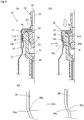
- the aerosol container 10 comprises a tubular bottomed container body 11 and an aerosol valve 12 firmly fixed to the opening of the container body.
- the seal between the aerosol container body 11 and the aerosol valve 12 is formed by a valve support portion 14 of the container body and a step portion 28 of the aerosol valve.
- a conventionally used elastic material such as synthetic rubber for sealing between the container body 11 and the aerosol valve 12 is not equipped.
- the container body 11 has pressure resistance comprising a bottom portion (not shown in the figure), a barrel portion 11a, a shoulder portion 11b, and a neck portion 11c, in which the upper end 11d of the neck portion forms the opening. Moreover, in the neck portion 11c, a valve support portion 14 protruding inward to support the valve is annularly formed.
- This container body 11 is an integrated body in which a tubular body is formed by impact forming from a metal plate such as aluminum. After that, the shoulder portion and the neck portion are formed by applying necking processing to the upper portion thereof. Moreover, a synthetic resin layer of polyamide-imide, epoxyphenol etc. is provided in the inner surface of the container body. Particularly, a synthetic resin layer of the thickness 3-30 ⁇ m, preferably 5 -25 ⁇ m is formed at least in the inner surface of the opening.
- the size of the container 11 is 10-25 mm in the diameter of the barrel portion 11a, preferably 12-20 mm, and is 8-20 mm in the diameter of the neck portion 11c, preferably 10-18 mm.
- the thickness of the container body is 0.3-1.0 mm, preferably, 0.5-0.9 mm.
- the aerosol valve 12 comprises a tubular housing 21, a stem 22 housed in the housing in a state being freely movable vertically, a spring 23 energizing the stem upward always, a stem rubber 24 plugging the stem hole of the stem, and a cup-like cover cap 25 which covers the upper portion of the housing 21 and is fixed to the container body 11. And, a dip tube 26 is attached to the lower end of the housing 21 of the aerosol valve.
- an annular flange portion 27 is formed in an upper periphery, an annular step portion 28 becoming smaller in diameter downward is formed beneath thereof, and a tube attaching portion 29 is formed in a bottom outside face, as shown in Figure 2a .
- the tube attaching portion 29 is tubular portion protruding from a lower face of the bottom of the housing 21.
- a stem rubber holding portion 30 recessed inward is formed, and a communicating hole 31 which communicates with the tube attaching portion 29 is formed in the bottom center.
- polyamide nylon
- polyacetal DRAKON
- polybutylene terephthalate etc.
- polyolefin particularly, polyethylene, polypropylene may be used.
- the stem 22 is a tubular member, which comprises an upper portion of which has a spout 33 equipped with the opening in the upper end, which has a stem hole 34 formed in the side face, which has an internal path 35 communicating with the spout 33 and the stem hole 34, and a lower portion where a spring engaging portion 36 to engage with the upper end of the spring 23 is formed.
- the spring 23 is held by the spring engaging portion 36 of the stem 22 and the bottom of the housing, energizing the stem 22 upward.
- the stem rubber 24 is that which is ring-like, housed in a stem rubber holding portion 30, and held between the stem rubber holding portion 30 and the inside of an upper bottom portion of the cover cap. In the center hole, the stem 22 is inserted. The up/down movement of the stem opens and closes the stem hole 34.
- the cover cap 25 comprises an upper bottom portion 38 and a side wall portion 39 extending downward from the periphery of the upper bottom portion, and a center hole to pass the stem 22 is formed in the upper bottom portion 38.
- the whole of the aerosol container 12 is firmly fixed to the container body 11 by deforming (plastic deforming) the lower portion 39a (deformed portion) of the side wall portion 39 with a crimping claw or a roller in the direction of the container body.
- the aerosol container 10 is manufactured as follows. First, as shown in Figure 2a , the aerosol valve 12 is inserted into the opening of the aerosol container 11. On this occasion, the step portion 28 of the housing comes in contact with the inside face of the valve support portion 14 of the container body, and supports the aerosol valve 12. More specifically, the upper end 11d of neck portion of the container body slightly comes in contact with the flange portion 27 of the housing, or the flange portion 27 is located slightly upper than the upper end 11d of neck portion. After that, as shown in Figure 2b , the cover cap 25 is pressed downward (arrow head direction). Simultaneously, the lower portion 39a of the cover cap 25 is deformed (plastically deformed) toward the container body side (arrow head direction) by the crimping claw etc.
- an upper inclined plane 14a (the first portion) of the inside face of the valve support portion 14 of the container body presses a corner portion 28a of the step portion 28, and deforms the corner portion 28a of the step portion 28 into a curved surface shape.
- the valve support portion 14 of the container body plastically deforms slightly together with the plastic deformation of the lower portion 39a of the cover cap.
- the cover cap 25 is plastically deformed by being strongly pressed downward, the upper end 11d of the neck portion of the container body and the flange portion 27 of the housing strongly come in contact.
- the contact portion of the corner portion 28a and the valve support portion 14 become a plane from a line.
- a strong seal is annularly formed between the corner portion 28a of the step portion 28 and the upper inclined plane 14a of the valve support portion 14.
- the aerosol container 10 can seal up a content (aerosol composition) having a vapor pressure of 0.2-0.8 MPa, even if a conventional seal member is omitted.
- the corner portion 28a can somewhat deforms downwardly, which prevents the step portion 28 from cracking caused by a force applied.
- the step portion 28 may be made into a curved surface shape from the beginning, if it can be deformed in the process to plastic deform of the cover cap (valve attaching process). But it is preferable to be a cornered shape from the point that it is easily deformed according to the front edge shape of a crimp claw and a roller, and that it is easy to obtain a high sealing property.
- an upper seal portion is formed annularly between the upper end 11d of the neck portion of the container body and the flange portion 27 of the housing.
- This upper seal portion is not as strong as the seal between the step portion 28 and the valve support portion 14.
- the length from the valve support portion 14 of the container body to the upper end 11d of the neck portion is somewhat longer than the length from the flange portion 27 of the housing to the corner portion 28a, in a state of the manufactured aerosol container 10, they contact strongly.
- an annular line seal structure can be obtained between the upper end 11d of the neck portion and the flange portion 27.
- the upper end 11d of the neck portion cuts into the flange portion 27 forming a seal.
- the portion of the container body from the valve supporting 14 to the upper end 11d of the neck portion somewhat deforms elastically outward. Therefore the state where the upper end 11d of the neck portion strongly pushes the flange portion 27 is form and enhances a sealing force by the contact.
- the housing 21 is sandwichedly pressed from upper and lower directions of the inner face of the upper bottom portion of the cover cap and the upper end 11d of the neck portion at the annular flange portion 27, interdependently with an elastic sandwiching pressure by the curved portion.
- the housing 21 is stably fixed with regard to the upper and lower directions (upper holding structure). Hence, the seal is maintained although an upward force is applied to the housing by an inner pressure.
- the alignment of the housing 21 from the opening of the container body The fear of becoming out of alignment of the housing 21 from the opening of the container body is small, although the aerosol container 10 receives a force from outside.
- the housing 21 is constituted so that the corner portion 28a is not included more outside than the contact line connecting the two points of the housing.
- the contact line means a straight line not intersecting with other than a point or a line of the portion of the housing 21.
- the corner portion 28a in the circled portion of Figure 3a is arranged more inside than a contact line connecting the lower end periphery of the flange portion 27 of the housing, the lower end periphery 32 of the housing, and the lower end periphery 29a of the tube attaching portion.
- a plurality of ribs 27a extending vertically on the step portion 28 may be laid side by side annularly.
- the contact line becomes a line connecting the lower end periphery of the flange portion 27 and the lower end of the rib 27a, and the corner portion 28a of the step portion 28 in the circled portion of Figure 3b will be arranged inside of the contact line.
- the step portion 28 is thus arranged more inside than the contact line which makes the lower end periphery of the flange portion 27 to be one point, the step portion 28 will not contact the floor etc., and the shape of the corner portion 28a of the step portion 28a will be protected, even if the housing 12 happens to turn over during transportation.
- FIG. 4a An aerosol container 40 in accordance with the present invention is shown in Figure 4a .
- the aerosol container 40 of Figure 4a is provided with a lower step portion 46 (second step portion) below the step portion 28 of the housing.
- the lower face 41a of the flange portion 41 of the housing inclines downward in an outward direction.
- the top face 14c (the second portion of the container body) of the valve support portion and the outer surface 47 of the lower step portion 46 comes in contact, by plastic deforming the lower portion 39a of the cover cap.
- the housing 12 is fixed (lower holding structure) not only by being pressed from the vertical direction pressure of the cover cap 25 and the upper neck portion 11d of the container body by the upper holding structure, but also from the side face (lower holding structure), it is further stably fixed.
- a sealing effect can be also expected according to the degree of plastic deformation of the valve support portion 14.
- the low step portion 46 may be shaped into a plurality of longitudinal ribs annularly provided.
- the low step portion 46 is easy to be deformed by the plastic deformation of the valve support portion.
- the sealing property cannot be obtained, since the second step portion deforms together with the plastic deformation of valve support portion, the housing can be further stably fixed. This is because, if the distance of the radial direction between the step portion 28 and the lower step portion 46 is short, there is a fear that the crimp claw receives a counteracting force from the lower step portion 46, which causes an insufficient crimping.
- the lower step portion 46 will deform making it easy for the crimp claw to reach a predetermined position. Thereby, the deforming of the corner portion 28a of the step portion will be secured, and the sealing property will be stabilized.
- An aerosol container 50 of Figure 5a is that in which a small step portion 51 (second step portion) coming in contact with the valve support portion 14 is provided below the step portion 28 of the housing.
- the small step portion 51 is provided so that its position comes in contact with the upper inclined plane 14a of the valve support portion 14.
- it means that the first portion and the second portion of the container body are equipped in the upper inclined plane 14a.
- the different portion (the first portion and the second portion) of the upper inclined plane 14a of the inside of the valve support portion 14 of the container body depresses the step portion 28 and the small step portion 51 and deform the corner portion 28a of the step portion 28 and the corner portion 51a of the small step portion 51 into a curved surface shape, when plastic deforming the lower portion 39a of the cover cap.
- a surface contact (seal portion and lower seal portion) with the valve support portion 14 of the container body can be obtained, which further enhances the sealing property.
- at least two points of the step portion 28 and the small step portion 51 contact with the container body, enhancing the stability.
- Figure 5c, d, e show the shape of the small step portion of the housing before manufacturing the aerosol container 50.
- the small step portion 51 of Figure 5c is an enlarged view of a part of Figure 5b , in which the corner portion 51a is substantially a right angle so as to form a stairway shape with the step portion 28 and the small step portion 51.
- the small step portion 51 of Figure 5d is equipped with an inclined plane 51b so as to be along the upper inclined plane 14a of the valve support portion of the container body.
- the small step portion 51c of Figure 5e is equipped with a bended portion 51b which is bended not having the corner portion.
- the corner portion 51a, the inclined plane 51b, the bended portion 51c and the valve support portion forms the surface contact constituting the sealing structure, when in plastic deformation of the lower portion 39a of the cover cap.
- An aerosol container 55 of Figure 6a, 6b is equipped with an annular protruding portion 56 (the second step portion) having an upward step portion 56a and a downward step portion 56b below the step portion 28.
- this aerosol container 55 is constituted so that a substantially top or top face of the valve support portion 14 comes to the annular groove portion formed between the step portion 28 and the protruding portion 56, as shown in Figure 6b . Therefore, when the lower portion 39a of the cover cap is plastic deformed toward the container body side, the corner portion 28a of the step portion 28 surface-contacts with the upper inclined plane 14a (the first portion), and the upper step portion 56a of the protruding portion surface-contacts with the lower inclined plane 14b (the second portion) of the valve support portion. In other words, the corner portion 28a of the step portion 28 and the corner portion 56c of the upper step portion 56a are deformed.
- sealing portion and lower seal portion are formed with the valve support portion 14, enhancing the whole sealing property, by plastic deforming thus the lower portion 39a of the cover cap.
- this sealing structure becomes a shape in which a wedge is provided in the outer periphery of barrel portion of the housing, the container body serves as a structure to hold the housing vertically and horizontally, preventing the housing from becoming out of alignment when shocks are applied to the aerosol container.
- An aerosol container 60 of Figure 7a, b is that in which an annular rib 61 is formed on the surface 47 of the lower step portion 46 of the aerosol container 40 of Figure 4a .
- the top face 14c (the second portion) of the valve support portion 14 and the rib 61 contact strongly, forming the lower seal portion, by deforming the lower portion 39a of the cover cap inward.
- the housing 21 does not become out of alignment when receiving external forces, since the housing 21 is fixed being pressed from above and below (upper support structure) and from a side face (lower support structure).
- An aerosol container 65 of Figure 8a, b is that in which a container body 66 is not equipped with the valve support portion 14 before the aerosol container is manufactured.
- the cover cap 25 is fixed to the container body 66, in a state that the flange portion of the housing is supported by the upper end 11d of neck portion.
- the lower portion 39a of the cover cap 25 is plastic deformed, while the valve portion 14 is formed in the container body 66.
- aerosol container which is substantially same as the aerosol container 10 of Figure 1 is manufactured.
- one of the manufacturing processes of the container body before manufacturing the aerosol container can be omitted, admitting cost reduction.
- the distance from the valve support portion 14 to the top face of the cover cap 25 is not necessary to be managed.
- An aerosol container 70 of Figure 9a, b has a tongue piece 71 which annually protrude downwardly and inside from the corner portion 28a is equipped in the lower face of the step portion 28.
- Figure 9d is that in which a tongue piece 72 is formed on the corner portion of the step portion.
- a surface contact between the tongue piece 72 and the upper inclined plane 14a is formed constituting a sealing structure can be obtained, since the tongue piece 72 is elastically deformed along the upper inclined plane 14a, by plastic deforming the lower portion 39a of the cover cap. In this case, the contact area becomes large giving a high sealing property.
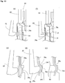
- the reference numeral 81 in the figure is a crimp claw
- the reference numeral 82 is a support rod.
- the crimp claw 81 plastically deforms the lower portion 39a of the cover cap, and simultaneously deforms the corner portion 28a of the step portion 28.
- Plurality of the crimp claw 81 is arranged annularly at an equal interval, so the corner portions 28a and the valve support portions 14 can form an annular seal.
- the support rod 82 presses the cover cap 25 downward, and a plurality of the support rod 82 is arranged cylindrically or annularly at an equal interval.
- the crimp claw 81 is set so that when it deforms the lower portion 39a of the cover cap, its radial inward force faces more upward than horizontal as large as an angle ⁇ .
- the front edge shape of the crimp claw is a convex surface shape.
- Figure 10c, d show a process to manufacture the aerosol container 55 of Figure 6 using a crimp claw 85.
- the seals are constituted between the upper inclined plane 14a of the valve support portion and the corner portion 28a of the step portion 28, and between the lower inclined plane 14b of the valve support portion and a corner portion 56c of an upper step portion 56a, by plastic deforming the lower portion 39a of the cover cap.
- the front edge of a claw portion 86 is dimensioned so as to be insertable between the step portion 28 and a protruding portion 56, and set so that the radial inward force of the upper portion of the front edge faces more upward than horizontal as large as an angle ⁇ , and the lower portion of the front edge composes an inclined plane so as to expand downward. Since being constituted thus, the front edge deforms the corner portion 28a of the step portion 28 and the corner portion 56c of the upper step portion 56a (refer to Figure 10d ).
- Figure 10e is an outline drawing of manufacturing the aerosol container 55 of Figure 6a , b.
Landscapes
- Chemical & Material Sciences (AREA)
- Dispersion Chemistry (AREA)
- Engineering & Computer Science (AREA)
- Mechanical Engineering (AREA)
- Containers And Packaging Bodies Having A Special Means To Remove Contents (AREA)
- Nozzles (AREA)
Claims (17)
- Structure d'étanchéité d'un récipient d'aérosol (40, 50, 55, 60), comprenant :un corps de récipient (11) présentant une ouverture de forme cylindrique ;un logement tubulaire (21) fixé sur l'ouverture ; etun capuchon en forme de coupelle (25) fixé sur le corps de récipient (11) et recouvrant le logement (21),le logement (21) présentant une partie d'épaulement annulaire (28), le capuchon (25) présentant une partie déformée (39a) sur une portion inférieure, la partie déformée (39a) étant déformée de manière plastique vers l'intérieur, etle corps de récipient (11) présentant une première partie (14a) qui vient au contact de la partie d'épaulement (28),où une partie d'étanchéité circulaire est formée entre la première partie (14a) et la partie d'épaulement (28), et la partie d'étanchéité est formée en déformant une partie de coin (28a) de la partie d'épaulement (28) en comprimant la première partie (14a) au moment de la formation de la partie déformée (39a) tout en poussant le capuchon (25) vers le bas contre le logement (21)caractérisée en ce queune deuxième partie d'épaulement (46, 51, 56) est située sous la partie d'épaulement (28),le corps de récipient présente une deuxième partie (14c) qui vient au contact de la deuxième partie d'épaulement (46, 51, 56), etle contact de la deuxième partie d'épaulement (46, 51, 56) et de la deuxième partie (14c) constitue une structure de maintien inférieure.
- Structure d'étanchéité selon la revendication 1,
dans laquelle la partie de coin (28a) de la partie d'épaulement (28) est déformée en une forme à surface courbe laquelle constitue un contact surfacique avec la première partie (14a) à partir d'une forme carrée laquelle constitue un contact linéaire avec la première partie (14a). - Structure d'étanchéité selon la revendication 1 ou la revendication 2,
dans laquelle le logement (21) présente une partie de bride (41) s'engageant avec une partie d'extrémité supérieure (11d) du corps de récipient (11) constituant l'ouverture,
et la partie de bride (41) constitue une structure de maintien supérieure bloquée entre la partie d'extrémité supérieure (11d) du corps de récipient (11) et une face inférieure intérieure du capuchon (25). - Structure d'étanchéité selon la revendication 3,
dans laquelle une face inférieure de la partie de bride (41) est inclinée vers le bas en direction de l'extérieur. - Structure d'étanchéité selon la revendication 1,
dans laquelle la deuxième partie d'épaulement (46, 51, 56) présente un plus petit diamètre que la partie d'épaulement (28),
et la deuxième partie (14c) du corps de récipient (11) vient au contact de la surface de la deuxième partie d'épaulement (46, 51, 56). - Structure d'étanchéité selon la revendication 5,
dans laquelle une nervure est prévue de manière annulaire sur une surface de la deuxième partie d'épaulement (46, 51, 56) et la deuxième partie (14c) déforme la nervure par compression. - Structure d'étanchéité selon la revendication 5,
dans laquelle la deuxième partie d'épaulement (46, 51, 56) est une pluralité de nervures longitudinales prévues de manière annulaire,
la deuxième partie (14c) déforme la nervure longitudinale par compression. - Structure d'étanchéité selon la revendication 1,
dans laquelle la deuxième partie (14c) vient au contact de la partie de coin de la deuxième partie d'épaulement (46, 51, 56). - Structure d'étanchéité selon la revendication 8,
dans laquelle la deuxième partie (14c) déforme la partie de coin de la deuxième partie d'épaulement (46, 51, 56). - Structure d'étanchéité selon la revendication 1,
dans laquelle un élément de languette (71) s'étendant vers le bas et formé sur un coté intérieur par rapport à la partie de coin (28a) de la partie d'épaulement (28) est prévu sur la surface inférieure de la partie d'épaulement (28),
et la partie de coin (28a) et l'élément de languette (71) sont déformés en venant au contact du corps de récipient (11). - Structure d'étanchéité selon la revendication 1,
dans laquelle une ligne de contact venant au contact du logement (21) en au moins deux points n'inclut pas la partie d'épaulement (28). - Structure d'étanchéité selon la revendication 11,
dans laquelle le logement (21) présente une partie de bride (41) s'engageant avec la partie d'extrémité supérieure (11d) du corps de récipient (11) constituant l'ouverture,
et une surface latérale du logement présente une protubérance faisant saillie vers l'extérieur dans une direction radiale, la protubérance constituant une ligne de contact avec un pourtour d'extrémité inférieure de la partie de bride (41). - Structure d'étanchéité selon l'une quelconque des revendications précédentes,
dans laquelle une couche de résine synthétique est prévue au moins sur une face intérieure de l'ouverture du corps de récipient (11). - Structure d'étanchéité selon l'une quelconque des revendications précédentes,
dans laquelle le logement est constitué de polyoléfine. - Récipient d'aérosol (40, 50, 55, 60) équipé de la structure d'étanchéité selon l'une quelconque des revendications 1 à 14, comprenant :le corps de récipient (11) et une valve de distribution d'aérosol (12) fixée sur l'ouverture du corps de récipient (11),où la valve de distribution d'aérosol (12) comprend le logement (21), une tige (22) logée dans le logement (21) de sorte à pouvoir se déplacer librement de manière verticale, un ressort (23) lequel exerce toujours une poussée vers le haut sur la tige (22), un caoutchouc de tige (24) lequel obture le trou de la tige (22), et le capuchon (25).
- Procédé de fabrication du récipient d'aérosol (40, 50, 55, 60) selon la revendication 15, comprenant l'étape consistant à déformer le coin (28a) de la partie d'épaulement (28) en une forme à surface courbe à partir d'une forme carrée, en appliquant une pression de manière annulaire sur la partie d'épaulement (28) à partir d'une surface convexe en déformant de manière plastique la portion inférieure du capuchon (25) et une portion du corps de récipient (11) tout en poussant le capuchon (25) vers le bas.
- Procédé de fabrication du récipient d'aérosol (40, 50, 55, 60) selon la revendication 16, comprenant en outre l'étape consistant à former la structure de maintien inférieure entre la deuxième partie (14c) et la deuxième partie d'épaulement (46, 51, 56) du corps de récipient, en même temps que la déformation plastique de la partie d'épaulement (28).
Applications Claiming Priority (2)
| Application Number | Priority Date | Filing Date | Title |
|---|---|---|---|
| JP2008263292 | 2008-10-09 | ||
| PCT/JP2009/067542 WO2010041709A1 (fr) | 2008-10-09 | 2009-10-08 | Structure d’étanchéité pour récipient d’aérosol, récipient d’aérosol, et procédé de fabrication de récipient d’aérosol |
Publications (3)
| Publication Number | Publication Date |
|---|---|
| EP2332854A1 EP2332854A1 (fr) | 2011-06-15 |
| EP2332854A4 EP2332854A4 (fr) | 2012-05-16 |
| EP2332854B1 true EP2332854B1 (fr) | 2018-05-23 |
Family
ID=42100657
Family Applications (1)
| Application Number | Title | Priority Date | Filing Date |
|---|---|---|---|
| EP09819243.8A Active EP2332854B1 (fr) | 2008-10-09 | 2009-10-08 | Structure d étanchéité pour récipient d aérosol, récipient d aérosol, et procédé de fabrication de récipient d aérosol |
Country Status (5)
| Country | Link |
|---|---|
| US (1) | US8746512B2 (fr) |
| EP (1) | EP2332854B1 (fr) |
| JP (1) | JP5380457B2 (fr) |
| CN (1) | CN102224087B (fr) |
| WO (1) | WO2010041709A1 (fr) |
Families Citing this family (10)
| Publication number | Priority date | Publication date | Assignee | Title |
|---|---|---|---|---|
| US7677420B1 (en) | 2004-07-02 | 2010-03-16 | Homax Products, Inc. | Aerosol spray texture apparatus for a particulate containing material |
| US7487893B1 (en) | 2004-10-08 | 2009-02-10 | Homax Products, Inc. | Aerosol systems and methods for dispensing texture material |
| FR2981054B1 (fr) * | 2011-10-05 | 2015-01-16 | Valois Sas | Element de fixation d'un organe de distribution sur le col d'un recipient et dispositif de distribution de produit fluide comportant un tel element de fixation. |
| US9435120B2 (en) | 2013-03-13 | 2016-09-06 | Homax Products, Inc. | Acoustic ceiling popcorn texture materials, systems, and methods |
| CA2859537C (fr) | 2013-08-19 | 2019-10-29 | Homax Products, Inc. | Materiaux, systemes et procedes de texture pour plafond |
| FR3019535B1 (fr) * | 2014-04-02 | 2016-03-25 | Rexam Healthcare La Verpillier | Ensemble de distribution d'un aerosol comportant une zone de contact perfectionnee avec un col de reservoir |
| USD787326S1 (en) | 2014-12-09 | 2017-05-23 | Ppg Architectural Finishes, Inc. | Cap with actuator |
| FR3051180B1 (fr) * | 2016-05-13 | 2019-07-26 | Aptar France Sas | Bague pour dispositif de distribution de produit fluide. |
| WO2020041792A1 (fr) | 2018-08-24 | 2020-02-27 | Clayton Corporation | Coupelle de montage en plastique et soupape pour récipient sous pression |
| CN110068420B (zh) * | 2019-04-28 | 2024-05-14 | 河南省计量测试科学研究院 | 一种预紧式自密封压力表接头 |
Family Cites Families (12)
| Publication number | Priority date | Publication date | Assignee | Title |
|---|---|---|---|---|
| DE9013730U1 (de) * | 1990-10-02 | 1992-02-06 | Hago-Chemotechnik GmbH & Co. KG, 8000 München | Einweg-Druckbehälter, insbesondere als Nachfüllbehälter für Kälte- und Klima-Anlagen |
| IT1254628B (it) * | 1992-02-21 | 1995-09-28 | Bomboletta spruzzatrice con valvola erogatrice preassemblata per l'erogazione di fluidi in genere. | |
| US5400920A (en) * | 1993-07-29 | 1995-03-28 | Minnesota Mining And Manufacturing Company | One-time fill aerosol valve |
| DE19632664B4 (de) * | 1996-08-14 | 2004-09-23 | Schott Glas | Glasfläschchen mit einem umspritzten Kunststoffüberzug, Verfahren zu seiner Herstellung und Vorrichtung zur Durchführung des Verfahrens |
| JPH10157750A (ja) * | 1996-10-02 | 1998-06-16 | Taisei Kako Kk | 金属製押出チューブ及びエアゾール缶、及び金属製押出チューブの製造方法 |
| JP3951045B2 (ja) | 2001-03-30 | 2007-08-01 | 株式会社ダイゾー | 小型圧力容器 |
| JP4148770B2 (ja) * | 2002-12-26 | 2008-09-10 | 花王株式会社 | エアゾール容器用バルブ機構 |
| SE0402434D0 (sv) * | 2004-10-08 | 2004-10-08 | Astrazeneca Ab | Inhaler valve |
| DE102005002444A1 (de) * | 2005-01-19 | 2006-07-27 | Wella Ag | Behälter mit einem Ventil |
| FR2885889B1 (fr) * | 2005-05-20 | 2007-10-19 | Valois Sas | Valve de distribution de produit fluide |
| FR2895374B1 (fr) * | 2005-12-27 | 2010-08-27 | Valois Sas | Bague pour valve aerosol. |
| FR2918044B1 (fr) * | 2007-06-28 | 2012-01-20 | Valois Sas | Bague pour valve de distribution de produit fluide. |
-
2009
- 2009-10-08 EP EP09819243.8A patent/EP2332854B1/fr active Active
- 2009-10-08 WO PCT/JP2009/067542 patent/WO2010041709A1/fr not_active Ceased
- 2009-10-08 CN CN2009801469413A patent/CN102224087B/zh active Active
- 2009-10-08 JP JP2010532953A patent/JP5380457B2/ja active Active
- 2009-10-08 US US13/123,193 patent/US8746512B2/en active Active
Non-Patent Citations (1)
| Title |
|---|
| None * |
Also Published As
| Publication number | Publication date |
|---|---|
| US8746512B2 (en) | 2014-06-10 |
| EP2332854A1 (fr) | 2011-06-15 |
| WO2010041709A1 (fr) | 2010-04-15 |
| JPWO2010041709A1 (ja) | 2012-03-08 |
| US20110240682A1 (en) | 2011-10-06 |
| EP2332854A4 (fr) | 2012-05-16 |
| CN102224087B (zh) | 2013-03-27 |
| CN102224087A (zh) | 2011-10-19 |
| JP5380457B2 (ja) | 2014-01-08 |
Similar Documents
| Publication | Publication Date | Title |
|---|---|---|
| EP2332854B1 (fr) | Structure d étanchéité pour récipient d aérosol, récipient d aérosol, et procédé de fabrication de récipient d aérosol | |
| US11000983B2 (en) | Plural nested preform assembly and method of manufacture | |
| US20090014679A1 (en) | Plastic aerosol valve and method of assembly, mounting and retention | |
| EP3169609B1 (fr) | Coupelle de montage de vanne pour un récipient sous pression | |
| KR102691763B1 (ko) | 유체 매체를 분사하기 위한 분사 시스템의 조립 방법 | |
| CN109689528B (zh) | 紧凑型气溶胶容器 | |
| JP5244173B2 (ja) | 流体ディスペンサ装置 | |
| CN104797508B (zh) | 排放容器以及排放容器的制造方法 | |
| CN102448852A (zh) | 分配多种液体用的气溶胶装置 | |
| US20180043603A1 (en) | Pressurized plural nested preform assembly and method of manufacture | |
| US11892084B2 (en) | Valve assembly for dispensers | |
| KR102385639B1 (ko) | 화장품 용기 | |
| US11835042B2 (en) | Pump for spraying liquid | |
| US11674615B2 (en) | Valve assembly for dispensers | |
| US11117736B2 (en) | Valve assembly for dispensers | |
| KR20210124889A (ko) | 액체 분사 펌프 | |
| JP5560035B2 (ja) | 内袋およびそれを用いた二重エアゾール製品 | |
| US7165701B2 (en) | Droplet nozzle for use in eye drop container | |
| US11703130B2 (en) | Valve assembly for dispensers | |
| US11674601B2 (en) | Valve assembly for dispensers | |
| KR20210136235A (ko) | 가변 배출 펌프 | |
| JP2008110807A (ja) | 二重エアゾール容器用の内袋および二重エアゾール容器ならびに二重エアゾール製品の製造法 | |
| US8505764B2 (en) | Structure of clinch portion of mounting cup | |
| US20230406576A1 (en) | Cap | |
| JP2006512185A (ja) | プラグ形状のポンプ |
Legal Events
| Date | Code | Title | Description |
|---|---|---|---|
| PUAI | Public reference made under article 153(3) epc to a published international application that has entered the european phase |
Free format text: ORIGINAL CODE: 0009012 |
|
| 17P | Request for examination filed |
Effective date: 20110406 |
|
| AK | Designated contracting states |
Kind code of ref document: A1 Designated state(s): AT BE BG CH CY CZ DE DK EE ES FI FR GB GR HR HU IE IS IT LI LT LU LV MC MK MT NL NO PL PT RO SE SI SK SM TR |
|
| AX | Request for extension of the european patent |
Extension state: AL BA RS |
|
| DAX | Request for extension of the european patent (deleted) | ||
| A4 | Supplementary search report drawn up and despatched |
Effective date: 20120418 |
|
| RIC1 | Information provided on ipc code assigned before grant |
Ipc: B05B 11/00 20060101ALI20120412BHEP Ipc: B65D 83/38 20060101AFI20120412BHEP |
|
| STAA | Information on the status of an ep patent application or granted ep patent |
Free format text: STATUS: EXAMINATION IS IN PROGRESS |
|
| 17Q | First examination report despatched |
Effective date: 20170517 |
|
| REG | Reference to a national code |
Ref country code: DE Ref legal event code: R079 Ref document number: 602009052459 Country of ref document: DE Free format text: PREVIOUS MAIN CLASS: B65D0083400000 Ipc: B65D0083380000 |
|
| GRAP | Despatch of communication of intention to grant a patent |
Free format text: ORIGINAL CODE: EPIDOSNIGR1 |
|
| STAA | Information on the status of an ep patent application or granted ep patent |
Free format text: STATUS: GRANT OF PATENT IS INTENDED |
|
| RIC1 | Information provided on ipc code assigned before grant |
Ipc: B65D 83/48 20060101ALN20180104BHEP Ipc: B65D 83/38 20060101AFI20180104BHEP Ipc: B05B 11/00 20060101ALI20180104BHEP |
|
| INTG | Intention to grant announced |
Effective date: 20180205 |
|
| GRAS | Grant fee paid |
Free format text: ORIGINAL CODE: EPIDOSNIGR3 |
|
| GRAA | (expected) grant |
Free format text: ORIGINAL CODE: 0009210 |
|
| STAA | Information on the status of an ep patent application or granted ep patent |
Free format text: STATUS: THE PATENT HAS BEEN GRANTED |
|
| AK | Designated contracting states |
Kind code of ref document: B1 Designated state(s): AT BE BG CH CY CZ DE DK EE ES FI FR GB GR HR HU IE IS IT LI LT LU LV MC MK MT NL NO PL PT RO SE SI SK SM TR |
|
| REG | Reference to a national code |
Ref country code: GB Ref legal event code: FG4D |
|
| REG | Reference to a national code |
Ref country code: CH Ref legal event code: EP |
|
| REG | Reference to a national code |
Ref country code: IE Ref legal event code: FG4D |
|
| REG | Reference to a national code |
Ref country code: AT Ref legal event code: REF Ref document number: 1001346 Country of ref document: AT Kind code of ref document: T Effective date: 20180615 |
|
| REG | Reference to a national code |
Ref country code: DE Ref legal event code: R096 Ref document number: 602009052459 Country of ref document: DE |
|
| REG | Reference to a national code |
Ref country code: NL Ref legal event code: MP Effective date: 20180523 |
|
| REG | Reference to a national code |
Ref country code: LT Ref legal event code: MG4D |
|
| REG | Reference to a national code |
Ref country code: FR Ref legal event code: PLFP Year of fee payment: 10 |
|
| PG25 | Lapsed in a contracting state [announced via postgrant information from national office to epo] |
Ref country code: LT Free format text: LAPSE BECAUSE OF FAILURE TO SUBMIT A TRANSLATION OF THE DESCRIPTION OR TO PAY THE FEE WITHIN THE PRESCRIBED TIME-LIMIT Effective date: 20180523 Ref country code: ES Free format text: LAPSE BECAUSE OF FAILURE TO SUBMIT A TRANSLATION OF THE DESCRIPTION OR TO PAY THE FEE WITHIN THE PRESCRIBED TIME-LIMIT Effective date: 20180523 Ref country code: NO Free format text: LAPSE BECAUSE OF FAILURE TO SUBMIT A TRANSLATION OF THE DESCRIPTION OR TO PAY THE FEE WITHIN THE PRESCRIBED TIME-LIMIT Effective date: 20180823 Ref country code: BG Free format text: LAPSE BECAUSE OF FAILURE TO SUBMIT A TRANSLATION OF THE DESCRIPTION OR TO PAY THE FEE WITHIN THE PRESCRIBED TIME-LIMIT Effective date: 20180823 Ref country code: SE Free format text: LAPSE BECAUSE OF FAILURE TO SUBMIT A TRANSLATION OF THE DESCRIPTION OR TO PAY THE FEE WITHIN THE PRESCRIBED TIME-LIMIT Effective date: 20180523 Ref country code: FI Free format text: LAPSE BECAUSE OF FAILURE TO SUBMIT A TRANSLATION OF THE DESCRIPTION OR TO PAY THE FEE WITHIN THE PRESCRIBED TIME-LIMIT Effective date: 20180523 |
|
| PG25 | Lapsed in a contracting state [announced via postgrant information from national office to epo] |
Ref country code: GR Free format text: LAPSE BECAUSE OF FAILURE TO SUBMIT A TRANSLATION OF THE DESCRIPTION OR TO PAY THE FEE WITHIN THE PRESCRIBED TIME-LIMIT Effective date: 20180824 Ref country code: LV Free format text: LAPSE BECAUSE OF FAILURE TO SUBMIT A TRANSLATION OF THE DESCRIPTION OR TO PAY THE FEE WITHIN THE PRESCRIBED TIME-LIMIT Effective date: 20180523 Ref country code: HR Free format text: LAPSE BECAUSE OF FAILURE TO SUBMIT A TRANSLATION OF THE DESCRIPTION OR TO PAY THE FEE WITHIN THE PRESCRIBED TIME-LIMIT Effective date: 20180523 Ref country code: NL Free format text: LAPSE BECAUSE OF FAILURE TO SUBMIT A TRANSLATION OF THE DESCRIPTION OR TO PAY THE FEE WITHIN THE PRESCRIBED TIME-LIMIT Effective date: 20180523 |
|
| REG | Reference to a national code |
Ref country code: AT Ref legal event code: MK05 Ref document number: 1001346 Country of ref document: AT Kind code of ref document: T Effective date: 20180523 |
|
| PG25 | Lapsed in a contracting state [announced via postgrant information from national office to epo] |
Ref country code: CZ Free format text: LAPSE BECAUSE OF FAILURE TO SUBMIT A TRANSLATION OF THE DESCRIPTION OR TO PAY THE FEE WITHIN THE PRESCRIBED TIME-LIMIT Effective date: 20180523 Ref country code: SK Free format text: LAPSE BECAUSE OF FAILURE TO SUBMIT A TRANSLATION OF THE DESCRIPTION OR TO PAY THE FEE WITHIN THE PRESCRIBED TIME-LIMIT Effective date: 20180523 Ref country code: PL Free format text: LAPSE BECAUSE OF FAILURE TO SUBMIT A TRANSLATION OF THE DESCRIPTION OR TO PAY THE FEE WITHIN THE PRESCRIBED TIME-LIMIT Effective date: 20180523 Ref country code: AT Free format text: LAPSE BECAUSE OF FAILURE TO SUBMIT A TRANSLATION OF THE DESCRIPTION OR TO PAY THE FEE WITHIN THE PRESCRIBED TIME-LIMIT Effective date: 20180523 Ref country code: EE Free format text: LAPSE BECAUSE OF FAILURE TO SUBMIT A TRANSLATION OF THE DESCRIPTION OR TO PAY THE FEE WITHIN THE PRESCRIBED TIME-LIMIT Effective date: 20180523 Ref country code: DK Free format text: LAPSE BECAUSE OF FAILURE TO SUBMIT A TRANSLATION OF THE DESCRIPTION OR TO PAY THE FEE WITHIN THE PRESCRIBED TIME-LIMIT Effective date: 20180523 Ref country code: RO Free format text: LAPSE BECAUSE OF FAILURE TO SUBMIT A TRANSLATION OF THE DESCRIPTION OR TO PAY THE FEE WITHIN THE PRESCRIBED TIME-LIMIT Effective date: 20180523 |
|
| REG | Reference to a national code |
Ref country code: DE Ref legal event code: R097 Ref document number: 602009052459 Country of ref document: DE |
|
| PG25 | Lapsed in a contracting state [announced via postgrant information from national office to epo] |
Ref country code: IT Free format text: LAPSE BECAUSE OF FAILURE TO SUBMIT A TRANSLATION OF THE DESCRIPTION OR TO PAY THE FEE WITHIN THE PRESCRIBED TIME-LIMIT Effective date: 20180523 Ref country code: SM Free format text: LAPSE BECAUSE OF FAILURE TO SUBMIT A TRANSLATION OF THE DESCRIPTION OR TO PAY THE FEE WITHIN THE PRESCRIBED TIME-LIMIT Effective date: 20180523 |
|
| PLBE | No opposition filed within time limit |
Free format text: ORIGINAL CODE: 0009261 |
|
| STAA | Information on the status of an ep patent application or granted ep patent |
Free format text: STATUS: NO OPPOSITION FILED WITHIN TIME LIMIT |
|
| 26N | No opposition filed |
Effective date: 20190226 |
|
| PG25 | Lapsed in a contracting state [announced via postgrant information from national office to epo] |
Ref country code: SI Free format text: LAPSE BECAUSE OF FAILURE TO SUBMIT A TRANSLATION OF THE DESCRIPTION OR TO PAY THE FEE WITHIN THE PRESCRIBED TIME-LIMIT Effective date: 20180523 |
|
| REG | Reference to a national code |
Ref country code: CH Ref legal event code: PL |
|
| REG | Reference to a national code |
Ref country code: BE Ref legal event code: MM Effective date: 20181031 |
|
| PG25 | Lapsed in a contracting state [announced via postgrant information from national office to epo] |
Ref country code: LU Free format text: LAPSE BECAUSE OF NON-PAYMENT OF DUE FEES Effective date: 20181008 Ref country code: MC Free format text: LAPSE BECAUSE OF FAILURE TO SUBMIT A TRANSLATION OF THE DESCRIPTION OR TO PAY THE FEE WITHIN THE PRESCRIBED TIME-LIMIT Effective date: 20180523 |
|
| REG | Reference to a national code |
Ref country code: IE Ref legal event code: MM4A |
|
| PG25 | Lapsed in a contracting state [announced via postgrant information from national office to epo] |
Ref country code: BE Free format text: LAPSE BECAUSE OF NON-PAYMENT OF DUE FEES Effective date: 20181031 Ref country code: CH Free format text: LAPSE BECAUSE OF NON-PAYMENT OF DUE FEES Effective date: 20181031 Ref country code: LI Free format text: LAPSE BECAUSE OF NON-PAYMENT OF DUE FEES Effective date: 20181031 |
|
| PG25 | Lapsed in a contracting state [announced via postgrant information from national office to epo] |
Ref country code: IE Free format text: LAPSE BECAUSE OF NON-PAYMENT OF DUE FEES Effective date: 20181008 |
|
| PG25 | Lapsed in a contracting state [announced via postgrant information from national office to epo] |
Ref country code: MT Free format text: LAPSE BECAUSE OF NON-PAYMENT OF DUE FEES Effective date: 20181008 |
|
| PG25 | Lapsed in a contracting state [announced via postgrant information from national office to epo] |
Ref country code: TR Free format text: LAPSE BECAUSE OF FAILURE TO SUBMIT A TRANSLATION OF THE DESCRIPTION OR TO PAY THE FEE WITHIN THE PRESCRIBED TIME-LIMIT Effective date: 20180523 |
|
| PG25 | Lapsed in a contracting state [announced via postgrant information from national office to epo] |
Ref country code: PT Free format text: LAPSE BECAUSE OF FAILURE TO SUBMIT A TRANSLATION OF THE DESCRIPTION OR TO PAY THE FEE WITHIN THE PRESCRIBED TIME-LIMIT Effective date: 20180523 |
|
| PG25 | Lapsed in a contracting state [announced via postgrant information from national office to epo] |
Ref country code: HU Free format text: LAPSE BECAUSE OF FAILURE TO SUBMIT A TRANSLATION OF THE DESCRIPTION OR TO PAY THE FEE WITHIN THE PRESCRIBED TIME-LIMIT; INVALID AB INITIO Effective date: 20091008 Ref country code: CY Free format text: LAPSE BECAUSE OF FAILURE TO SUBMIT A TRANSLATION OF THE DESCRIPTION OR TO PAY THE FEE WITHIN THE PRESCRIBED TIME-LIMIT Effective date: 20180523 Ref country code: MK Free format text: LAPSE BECAUSE OF NON-PAYMENT OF DUE FEES Effective date: 20180523 |
|
| PG25 | Lapsed in a contracting state [announced via postgrant information from national office to epo] |
Ref country code: IS Free format text: LAPSE BECAUSE OF FAILURE TO SUBMIT A TRANSLATION OF THE DESCRIPTION OR TO PAY THE FEE WITHIN THE PRESCRIBED TIME-LIMIT Effective date: 20180923 |
|
| PGFP | Annual fee paid to national office [announced via postgrant information from national office to epo] |
Ref country code: DE Payment date: 20211020 Year of fee payment: 13 |
|
| REG | Reference to a national code |
Ref country code: DE Ref legal event code: R119 Ref document number: 602009052459 Country of ref document: DE |
|
| PG25 | Lapsed in a contracting state [announced via postgrant information from national office to epo] |
Ref country code: DE Free format text: LAPSE BECAUSE OF NON-PAYMENT OF DUE FEES Effective date: 20230503 |
|
| PGFP | Annual fee paid to national office [announced via postgrant information from national office to epo] |
Ref country code: GB Payment date: 20241017 Year of fee payment: 16 |
|
| PGFP | Annual fee paid to national office [announced via postgrant information from national office to epo] |
Ref country code: FR Payment date: 20241021 Year of fee payment: 16 |