EP2332877A1 - Agencement pour détecter la propriété d'une charge manipulée par des supports de levage - Google Patents
Agencement pour détecter la propriété d'une charge manipulée par des supports de levage Download PDFInfo
- Publication number
- EP2332877A1 EP2332877A1 EP09178267A EP09178267A EP2332877A1 EP 2332877 A1 EP2332877 A1 EP 2332877A1 EP 09178267 A EP09178267 A EP 09178267A EP 09178267 A EP09178267 A EP 09178267A EP 2332877 A1 EP2332877 A1 EP 2332877A1
- Authority
- EP
- European Patent Office
- Prior art keywords
- boom
- load
- sensor
- signal
- arrangement according
- Prior art date
- Legal status (The legal status is an assumption and is not a legal conclusion. Google has not performed a legal analysis and makes no representation as to the accuracy of the status listed.)
- Granted
Links
Images

Classifications
-
- B—PERFORMING OPERATIONS; TRANSPORTING
- B66—HOISTING; LIFTING; HAULING
- B66C—CRANES; LOAD-ENGAGING ELEMENTS OR DEVICES FOR CRANES, CAPSTANS, WINCHES, OR TACKLES
- B66C13/00—Other constructional features or details
- B66C13/16—Applications of indicating, registering, or weighing devices
-
- G—PHYSICS
- G01—MEASURING; TESTING
- G01G—WEIGHING
- G01G19/00—Weighing apparatus or methods adapted for special purposes not provided for in the preceding groups
- G01G19/14—Weighing apparatus or methods adapted for special purposes not provided for in the preceding groups for weighing suspended loads
- G01G19/18—Weighing apparatus or methods adapted for special purposes not provided for in the preceding groups for weighing suspended loads having electrical weight-sensitive devices
-
- G—PHYSICS
- G01—MEASURING; TESTING
- G01G—WEIGHING
- G01G23/00—Auxiliary devices for weighing apparatus
- G01G23/18—Indicating devices, e.g. for remote indication; Recording devices; Scales, e.g. graduated
- G01G23/36—Indicating the weight by electrical means, e.g. using photoelectric cells
- G01G23/37—Indicating the weight by electrical means, e.g. using photoelectric cells involving digital counting
- G01G23/3728—Indicating the weight by electrical means, e.g. using photoelectric cells involving digital counting with wireless means
- G01G23/3735—Indicating the weight by electrical means, e.g. using photoelectric cells involving digital counting with wireless means using a digital network
Definitions
- This invention relates generally to an arrangement for detecting a property of load manipulated by lifting means.
- the present invention van be applied e.g. in a weighing arrangement, which is used for weighing material being lifted with a crane of a material transfer vehicle, for example.
- the material transfer vehicle may be e.g. a timber truck, a forwarder or a harvester.
- Cranes often include a weighing arrangement for weighing the material being lifted.
- a crane with a prior art weighing arrangement is disclosed in a patent document FI84759 and illustrated in Figure 1 .
- the crane includes movable boom which has several beams with articulated joints.
- rotator 5 coupled to the boom.
- material actuating means 6 such as a grapple head for catching timber.
- sensor element 1 between the boom and the rotator for measuring the weight of the load.
- the sensor element 1 is attached between the boom and the rotator with joints 8, 9.
- the signal from the sensor is lead through a signal cable 2 to amplifier 3, and the amplified signal is further led with a cable to a measurement/control unit 4 which includes a user interface.
- a measurement/control unit 4 which includes a user interface.
- a hydraulic measurement there is a hydraulic cylinder at the sensor element 1, and a hydraulic hose 2 is led from the measurement point 1 to a unit 3 including a pressure sensor and amplifier.
- the signal is further led via an electric cable to the measurement/control unit 4.
- the objective of the present invention is to avoid or at least alleviate the aforesaid defects of prior art solutions and to achieve a solution by which a more reliable functionality is achieved.
- the object of the invention is met by a solution, wherein there is an electronic or hydraulic sensor, preferably installed between the boom and the rotating part of the rotator of the lifting means, and a signal from the sensor is lead by an electric or hydraulic cable to an electronics unit which is located at the boom of the lifting means.
- the electronics unit has means for wireless data transfer and an energy source for signal processing means and data transfer means.
- the arrangement comprises:
- the senor is an electrical sensor, such as a strain gauge for weighing the load.
- the sensor associated electronics such as an amplifier and/or analog-to-digital converter is integrated to a same housing with the sensor.
- the sensor associated electronics such as an amplifier and/or analog-to-digital converter is located in the electronics unit.
- the senor is a hydraulic sensor, such as a hydraulic cylinder, which is connected to the electronics unit with a hydraulic hose.
- the hydraulic cylinder may thus be a part of a hanger.
- the electronics unit includes a pressure sensor for converting the hydraulic pressure into an electric signal.
- the hydraulic sensor is preferably used for weighing the load.
- the pressure sensor is located by the hydraulic cylinder, and there is a signal cable between the pressure sensor and the electronics unit.
- the sensor may also read/measure some other property of the load than weight. It may be e.g. a reader for an RFID tag which is attached to the load.
- the RFID tag may include information about the load such as quality, owner or transport destination of the load etc.
- the sensor may also measure either properties of the load than weight, such as width of the load. Such a sensor may be based on mechanical or optical measurement, for example.
- the energy source of the electronics unit may preferably be a loadable battery. There may also be a solar cell or a generator which produces electrical energy from movement of the lifting means. Such means can be used as the primary energy source or they can be used for loading a battery.
- the senor can be a small, simple and compact component, which is easy install between the boom and the rotating part of the rotator, such as into a hanger between the boom end and the rotator.
- the electronics unit for transmission electronics and battery can be installed inside the boom, whereby the risk for direct physical impacts to the unit is very small. It is also possible to use a large space for the electronics unit, whereby it is possible to use a battery with large capacity, or other kinds of energy sources.
- the "material transfer vehicle” refers at least to all kinds of vehicles having lifting means and manipulating means for lifting/transferring material loads.
- the transfer vehicle may be e.g. a timber truck, a forwarder or a harvester.
- the lifted/transferred material may be e.g. timber or other longitudinal material, rocks, other piece material, etc.
- rotating part means the part of a rotator, which is arranged to rotate in relation to the boom of the lifting means.
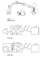
- FIG. 2a illustrates a block diagram for an arrangement according to an embodiment of the invention.
- a sensor 21 which gives an electrical signal including information on a property of the load.
- the sensor may be e.g. a strain gauge, whereby the signal is proportional to the weight of the load.
- the sensor 21 is installed between the boom and the rotating part of the rotator of the lifting means.
- the sensor may be installed in a hanger or in a a non-rotating part of the rotator, for example.
- the signal from the sensor is led through a cable 22 into an electronics unit 25, which is installed at the boom of the lifting means.
- the electronics unit may preferably be installed inside the boom, but it alternatively also be installed partly or in whole outside the actual boom structure at its side.
- the electronics unit 25 includes signal processing means 28, which amplifies the signal received from the sensor, and converts the signal into digital mode.
- the digital sensor signal is then led to data transfer means 27, which transmit the data in a wireless way through an antenna 29.
- the electronics unit also includes an energy source 26, such as a loadable battery, for supplying electricity to the signal processing means and the data transfer means. There may also or alternatively be a solar cell, or a transducer for converting movement of the boom into electrical energy.
- the transmitted signal is received at the antenna 23 of the measurement/control unit 24, wherein the signal is converted into displayed information, such as weight information.
- the measurement/control unit may be located at the cabin of the material transfer vehicle.
- the wireless data transmission may be based on radio modem channels, Bluetooth, WLAN (Wireless Local Area Network), mobile phone networks, such as GPRS, or it may be based on some other wireless communication method.
- FIG. 2b illustrates a block diagram for an arrangement according to a second embodiment of the invention.
- a sensor 21 which gives an electrical signal including information on a property of the load.
- the sensor may thus be e.g. a strain gauge, whereby the signal is proportional to the weight of the load.
- the signal processing means 28 is integrated with the sensor 21 into an integrated component.
- This sensor component is installed between the boom and the rotating part of the rotator of the lifting means.
- the sensor and signal processing component may be installed in a hanger or in a non-rotating part of the rotator, for example..
- the processed signal is led through a cable 22 into an electronics unit 25, which is installed at the boom of the lifting means.
- the electronics unit may preferably be installed inside the boom, but it alternatively also be installed partly or in whole outside the actual boom structure at its side.
- the electronics unit 25 includes data transfer means 27, which transmit the data in a wireless way through an antenna 29.
- the electronics unit also includes an energy source 26, such as a loadable battery, for supplying electricity to the signal processing means 28 and the data transfer means 27. There may also or alternatively be a solar cell, or a transducer for converting movement of the boom into electrical energy.
- the cable 22 also includes wires for supplying voltage to the signal processing means which are located between the boom and the rotating part of the rotator in this embodiment.
- the transmitted signal is received at the antenna 23 of the measurement/control unit 24, wherein the signal is converted into displayed information, such as weight information.
- the signal on the cable 22 has higher amplitude, and is therefore less sensitive to interference.
- FIG. 2c illustrates a block diagram for an arrangement according to a third embodiment of the invention.
- a hydraulic cylinder 21a as a sensor, which is installed between the boom and the rotating part of the rotator of the lifting means.
- the hydraulic cylinder may be installed in a hanger thus forming a part of the hanger, or in a non-rotating part of the rotator.
- the pressure from the hydraulic cylinder is led through a hydraulic hose 22 into an electronics unit 25, which is installed at the boom of the lifting means.
- the electronics unit 25 includes a pressure sensor 21b, which converts the hydraulic pressure into an electrical signal.
- the pressure sensor 21b is integrated with the hydraulic cylinder 21a and thus located between the boom end and the rotating part of the rotator.
- the arrangement comprises an electric cable 22 from the pressure sensor to the electronics unit 25, instead of a hydraulic hose.
- the electronics unit includes signal processing means 28, which amplifies the signal received from the sensor, and converts the signal into digital mode.
- the signal processing means is integrated with the hydraulic cylinder and the pressure sensor, which all locate between the boom end and the rotating part of the rotator.
- the digital sensor signal is led to data transfer means 27, which transmit the data in a wireless way through an antenna 29.
- the electronics unit also includes an energy source 26, such as a loadable battery, for supplying electricity to the signal processing means and the data transfer means. There may also or alternatively be a solar cell, or a transducer for converting movement of the boom into electrical energy.
- the transmitted signal is received at the antenna 23 of the measurement/control unit 24, wherein the signal is converted into displayed information, such as weight information.
- the measurement/control unit may be located at the cabin of the material transfer vehicle.
- the measurement/control unit preferably includes both input and output user interface, such as a keyboard, push buttons, a display and/or a touch screen, for example for example, the weighing equipment may perform the weighing of the load during the load is lifted to the loading space of the vehicle, and display the weighing results at the display of the measurement/control unit.
- the user may indicate that the measurement result is saved by pressing a corresponding push button, for example, whereby the arrangement is adapted to register the detected weight of the load.
- the registering is activated when the boom's position is within certain limits, such as when the boom is turned between the studs of a timber truck or a forwarder to which the boom is articulated.
- It is also possible to calculate a standard deviation of a continuous detection of the load weight whereby the measurement result is registered when the standard deviation value is within a certain limit. It is also possible to provide some other triggering signal for the detection of the measurement.
- the senor may also read/measure some other property of the load than weight. It may be e.g. a reader for an RFID tag which is attached to the load.
- the RFID tag may include information about the load such as quality, owner or transport destination of the load etc.
- the sensor may also measure either properties of the load than weight, such as width of the load. Such a sensor may be based on mechanical or optical measurement, for example.
Landscapes
- Physics & Mathematics (AREA)
- General Physics & Mathematics (AREA)
- Engineering & Computer Science (AREA)
- Mechanical Engineering (AREA)
- Computer Networks & Wireless Communication (AREA)
- Arrangements For Transmission Of Measured Signals (AREA)
Priority Applications (2)
| Application Number | Priority Date | Filing Date | Title |
|---|---|---|---|
| PL09178267T PL2332877T3 (pl) | 2009-12-08 | 2009-12-08 | Układ do wykrywania właściwości ładunku obsługiwanego przez elementy dźwigowe |
| EP09178267A EP2332877B1 (fr) | 2009-12-08 | 2009-12-08 | Agencement pour détecter la propriété d'une charge manipulée par des supports de levage |
Applications Claiming Priority (1)
| Application Number | Priority Date | Filing Date | Title |
|---|---|---|---|
| EP09178267A EP2332877B1 (fr) | 2009-12-08 | 2009-12-08 | Agencement pour détecter la propriété d'une charge manipulée par des supports de levage |
Publications (2)
| Publication Number | Publication Date |
|---|---|
| EP2332877A1 true EP2332877A1 (fr) | 2011-06-15 |
| EP2332877B1 EP2332877B1 (fr) | 2012-08-08 |
Family
ID=42126339
Family Applications (1)
| Application Number | Title | Priority Date | Filing Date |
|---|---|---|---|
| EP09178267A Active EP2332877B1 (fr) | 2009-12-08 | 2009-12-08 | Agencement pour détecter la propriété d'une charge manipulée par des supports de levage |
Country Status (2)
| Country | Link |
|---|---|
| EP (1) | EP2332877B1 (fr) |
| PL (1) | PL2332877T3 (fr) |
Cited By (7)
| Publication number | Priority date | Publication date | Assignee | Title |
|---|---|---|---|---|
| CN102785990A (zh) * | 2012-07-24 | 2012-11-21 | 中国矿业大学 | 一种具有滑触线的矿井罐笼系统及其升降控制方法 |
| WO2013030269A1 (fr) * | 2011-08-31 | 2013-03-07 | Hirschmann Automation And Control Gmbh | Mesure de charge sur l'organe porte-charge d'engins de levage |
| WO2014081378A1 (fr) * | 2012-11-20 | 2014-05-30 | Komatsu Forest Ab | Système de pesée pour charges manipulées par un équipement de levage |
| JP2017036583A (ja) * | 2015-08-10 | 2017-02-16 | 日本車輌製造株式会社 | 建設機械 |
| EP3219661A3 (fr) * | 2016-03-14 | 2017-11-08 | Goodrich Corporation | Systèmes de détection des charges de levage de sauvetage |
| RU184415U1 (ru) * | 2017-05-10 | 2018-10-24 | Федеральное государственное бюджетное образовательное учреждение высшего образования "Уральский государственный лесотехнический университет" | Весоизмерительное устройство лесовозного автомобиля с гидроманипулятором |
| CN110921511A (zh) * | 2019-11-29 | 2020-03-27 | 中联重科股份有限公司 | 应用于起重机吊臂的信号传输系统、方法以及起重机 |
Citations (5)
| Publication number | Priority date | Publication date | Assignee | Title |
|---|---|---|---|---|
| WO1997040352A1 (fr) * | 1996-04-24 | 1997-10-30 | Hardy Instruments, Inc. | Systeme et procede de pesage de dechets |
| US20030102170A1 (en) * | 2001-11-30 | 2003-06-05 | Simons Gerald S. | Standard attachment fittings for wire rope and chain enhanced to also perform load weighing functions |
| WO2004005180A1 (fr) * | 2002-07-02 | 2004-01-15 | Plustech Oy | Systeme de pesage de charges dans un appareil de levage et de transfert |
| JP2006250582A (ja) * | 2005-03-08 | 2006-09-21 | Hitachi Plant Technologies Ltd | 荷重センサ付きrfidタグ |
| US20070013199A1 (en) * | 2005-07-12 | 2007-01-18 | Novatek International, Inc. | Clamping assembly |
-
2009
- 2009-12-08 EP EP09178267A patent/EP2332877B1/fr active Active
- 2009-12-08 PL PL09178267T patent/PL2332877T3/pl unknown
Patent Citations (5)
| Publication number | Priority date | Publication date | Assignee | Title |
|---|---|---|---|---|
| WO1997040352A1 (fr) * | 1996-04-24 | 1997-10-30 | Hardy Instruments, Inc. | Systeme et procede de pesage de dechets |
| US20030102170A1 (en) * | 2001-11-30 | 2003-06-05 | Simons Gerald S. | Standard attachment fittings for wire rope and chain enhanced to also perform load weighing functions |
| WO2004005180A1 (fr) * | 2002-07-02 | 2004-01-15 | Plustech Oy | Systeme de pesage de charges dans un appareil de levage et de transfert |
| JP2006250582A (ja) * | 2005-03-08 | 2006-09-21 | Hitachi Plant Technologies Ltd | 荷重センサ付きrfidタグ |
| US20070013199A1 (en) * | 2005-07-12 | 2007-01-18 | Novatek International, Inc. | Clamping assembly |
Cited By (13)
| Publication number | Priority date | Publication date | Assignee | Title |
|---|---|---|---|---|
| US9274011B2 (en) | 2011-08-31 | 2016-03-01 | Hirschmann Automation And Control Gmbh | Load measurement of the load receiver of hoisting devices |
| WO2013030269A1 (fr) * | 2011-08-31 | 2013-03-07 | Hirschmann Automation And Control Gmbh | Mesure de charge sur l'organe porte-charge d'engins de levage |
| CN103764539A (zh) * | 2011-08-31 | 2014-04-30 | 赫思曼自动化控制有限公司 | 起重机的负载承受器上的负载测量 |
| US20140216171A1 (en) * | 2011-08-31 | 2014-08-07 | Helmuth Kettenbach | Load measurement of the load receiver of hoisting devices |
| CN102785990B (zh) * | 2012-07-24 | 2013-12-25 | 中国矿业大学 | 一种具有滑触线的矿井罐笼系统及其升降控制方法 |
| CN102785990A (zh) * | 2012-07-24 | 2012-11-21 | 中国矿业大学 | 一种具有滑触线的矿井罐笼系统及其升降控制方法 |
| WO2014081378A1 (fr) * | 2012-11-20 | 2014-05-30 | Komatsu Forest Ab | Système de pesée pour charges manipulées par un équipement de levage |
| US9708165B2 (en) | 2012-11-20 | 2017-07-18 | Komatsu Forest Ab | Weighing system for loads manipulated by lifting equipment |
| JP2017036583A (ja) * | 2015-08-10 | 2017-02-16 | 日本車輌製造株式会社 | 建設機械 |
| EP3219661A3 (fr) * | 2016-03-14 | 2017-11-08 | Goodrich Corporation | Systèmes de détection des charges de levage de sauvetage |
| RU184415U1 (ru) * | 2017-05-10 | 2018-10-24 | Федеральное государственное бюджетное образовательное учреждение высшего образования "Уральский государственный лесотехнический университет" | Весоизмерительное устройство лесовозного автомобиля с гидроманипулятором |
| RU184415U9 (ru) * | 2017-05-10 | 2018-12-07 | Федеральное государственное бюджетное образовательное учреждение высшего образования "Уральский государственный лесотехнический университет" | Весоизмерительное устройство лесовозного автомобиля с гидроманипулятором |
| CN110921511A (zh) * | 2019-11-29 | 2020-03-27 | 中联重科股份有限公司 | 应用于起重机吊臂的信号传输系统、方法以及起重机 |
Also Published As
| Publication number | Publication date |
|---|---|
| PL2332877T3 (pl) | 2012-12-31 |
| EP2332877B1 (fr) | 2012-08-08 |
Similar Documents
| Publication | Publication Date | Title |
|---|---|---|
| EP2332877B1 (fr) | Agencement pour détecter la propriété d'une charge manipulée par des supports de levage | |
| CN105980821B (zh) | 用于确定支承力的测量系统 | |
| CN101799314B (zh) | 集装箱超偏载检测称重系统装置 | |
| EP2511678B1 (fr) | Système de mesure pour véhicule de transfert de matériel | |
| US5160055A (en) | Load moment indicator system | |
| US9274011B2 (en) | Load measurement of the load receiver of hoisting devices | |
| US20120312767A1 (en) | Method of monitoring crane safety during the setup procedure, as well as crane and crane control | |
| US10358322B2 (en) | Load weighing at the lifting hook | |
| EP3409635B1 (fr) | Système de pesage pour un dispositif de levage | |
| CN201594007U (zh) | 集装箱超偏载检测称重系统装置 | |
| CN2892799Y (zh) | 无线数传起重机安全综合保护装置 | |
| KR20160043875A (ko) | 크레인 모니터링 장치 | |
| CN203772457U (zh) | 用于确定在支承结构的支承元件上的支承力的测量系统 | |
| KR101121689B1 (ko) | 크레인 하중센서 | |
| CN205993818U (zh) | 一种智能行李箱 | |
| KR100533338B1 (ko) | 블루투스를 이용한 로드셀 인디케이터 표시 시스템 | |
| CN210505279U (zh) | 一种集装箱起重机钮锁寿命管理系统 | |
| CN212769495U (zh) | 一种起重机超载重量监测装置 | |
| RU2445252C1 (ru) | Ограничитель нагрузки грузоподъемного крана | |
| CN114413964A (zh) | 一种多传感器采集系统 | |
| CN104071697A (zh) | 起重机及其远程称量装置 | |
| GB2487608A (en) | Clevis pin strain sensor for vehicle payload weighing | |
| EP2240748A1 (fr) | Systeme indicateur de charge | |
| JP2021031268A (ja) | 産業車両管理システム | |
| CN221720332U (zh) | 一种岸桥称重装置 |
Legal Events
| Date | Code | Title | Description |
|---|---|---|---|
| PUAI | Public reference made under article 153(3) epc to a published international application that has entered the european phase |
Free format text: ORIGINAL CODE: 0009012 |
|
| AK | Designated contracting states |
Kind code of ref document: A1 Designated state(s): AT BE BG CH CY CZ DE DK EE ES FI FR GB GR HR HU IE IS IT LI LT LU LV MC MK MT NL NO PL PT RO SE SI SK SM TR |
|
| AX | Request for extension of the european patent |
Extension state: AL BA RS |
|
| 17P | Request for examination filed |
Effective date: 20111214 |
|
| GRAP | Despatch of communication of intention to grant a patent |
Free format text: ORIGINAL CODE: EPIDOSNIGR1 |
|
| RIC1 | Information provided on ipc code assigned before grant |
Ipc: G01G 19/18 20060101ALI20120124BHEP Ipc: G01G 23/37 20060101ALI20120124BHEP Ipc: B66C 13/16 20060101AFI20120124BHEP |
|
| GRAS | Grant fee paid |
Free format text: ORIGINAL CODE: EPIDOSNIGR3 |
|
| GRAA | (expected) grant |
Free format text: ORIGINAL CODE: 0009210 |
|
| AK | Designated contracting states |
Kind code of ref document: B1 Designated state(s): AT BE BG CH CY CZ DE DK EE ES FI FR GB GR HR HU IE IS IT LI LT LU LV MC MK MT NL NO PL PT RO SE SI SK SM TR |
|
| REG | Reference to a national code |
Ref country code: GB Ref legal event code: FG4D |
|
| REG | Reference to a national code |
Ref country code: CH Ref legal event code: EP Ref country code: AT Ref legal event code: REF Ref document number: 569647 Country of ref document: AT Kind code of ref document: T Effective date: 20120815 |
|
| REG | Reference to a national code |
Ref country code: IE Ref legal event code: FG4D |
|
| REG | Reference to a national code |
Ref country code: DE Ref legal event code: R096 Ref document number: 602009008787 Country of ref document: DE Effective date: 20121004 |
|
| REG | Reference to a national code |
Ref country code: SE Ref legal event code: TRGR |
|
| REG | Reference to a national code |
Ref country code: NL Ref legal event code: VDEP Effective date: 20120808 |
|
| REG | Reference to a national code |
Ref country code: AT Ref legal event code: MK05 Ref document number: 569647 Country of ref document: AT Kind code of ref document: T Effective date: 20120808 |
|
| REG | Reference to a national code |
Ref country code: PL Ref legal event code: T3 |
|
| REG | Reference to a national code |
Ref country code: LT Ref legal event code: MG4D Effective date: 20120808 |
|
| PG25 | Lapsed in a contracting state [announced via postgrant information from national office to epo] |
Ref country code: HR Free format text: LAPSE BECAUSE OF FAILURE TO SUBMIT A TRANSLATION OF THE DESCRIPTION OR TO PAY THE FEE WITHIN THE PRESCRIBED TIME-LIMIT Effective date: 20120808 Ref country code: IS Free format text: LAPSE BECAUSE OF FAILURE TO SUBMIT A TRANSLATION OF THE DESCRIPTION OR TO PAY THE FEE WITHIN THE PRESCRIBED TIME-LIMIT Effective date: 20121208 Ref country code: CY Free format text: LAPSE BECAUSE OF FAILURE TO SUBMIT A TRANSLATION OF THE DESCRIPTION OR TO PAY THE FEE WITHIN THE PRESCRIBED TIME-LIMIT Effective date: 20120808 Ref country code: AT Free format text: LAPSE BECAUSE OF FAILURE TO SUBMIT A TRANSLATION OF THE DESCRIPTION OR TO PAY THE FEE WITHIN THE PRESCRIBED TIME-LIMIT Effective date: 20120808 Ref country code: NO Free format text: LAPSE BECAUSE OF FAILURE TO SUBMIT A TRANSLATION OF THE DESCRIPTION OR TO PAY THE FEE WITHIN THE PRESCRIBED TIME-LIMIT Effective date: 20121108 Ref country code: LT Free format text: LAPSE BECAUSE OF FAILURE TO SUBMIT A TRANSLATION OF THE DESCRIPTION OR TO PAY THE FEE WITHIN THE PRESCRIBED TIME-LIMIT Effective date: 20120808 |
|
| REG | Reference to a national code |
Ref country code: SK Ref legal event code: T3 Ref document number: E 12864 Country of ref document: SK |
|
| PG25 | Lapsed in a contracting state [announced via postgrant information from national office to epo] |
Ref country code: SI Free format text: LAPSE BECAUSE OF FAILURE TO SUBMIT A TRANSLATION OF THE DESCRIPTION OR TO PAY THE FEE WITHIN THE PRESCRIBED TIME-LIMIT Effective date: 20120808 Ref country code: PT Free format text: LAPSE BECAUSE OF FAILURE TO SUBMIT A TRANSLATION OF THE DESCRIPTION OR TO PAY THE FEE WITHIN THE PRESCRIBED TIME-LIMIT Effective date: 20121210 Ref country code: GR Free format text: LAPSE BECAUSE OF FAILURE TO SUBMIT A TRANSLATION OF THE DESCRIPTION OR TO PAY THE FEE WITHIN THE PRESCRIBED TIME-LIMIT Effective date: 20121109 Ref country code: BE Free format text: LAPSE BECAUSE OF FAILURE TO SUBMIT A TRANSLATION OF THE DESCRIPTION OR TO PAY THE FEE WITHIN THE PRESCRIBED TIME-LIMIT Effective date: 20120808 Ref country code: LV Free format text: LAPSE BECAUSE OF FAILURE TO SUBMIT A TRANSLATION OF THE DESCRIPTION OR TO PAY THE FEE WITHIN THE PRESCRIBED TIME-LIMIT Effective date: 20120808 |
|
| PG25 | Lapsed in a contracting state [announced via postgrant information from national office to epo] |
Ref country code: NL Free format text: LAPSE BECAUSE OF FAILURE TO SUBMIT A TRANSLATION OF THE DESCRIPTION OR TO PAY THE FEE WITHIN THE PRESCRIBED TIME-LIMIT Effective date: 20120808 |
|
| PG25 | Lapsed in a contracting state [announced via postgrant information from national office to epo] |
Ref country code: ES Free format text: LAPSE BECAUSE OF FAILURE TO SUBMIT A TRANSLATION OF THE DESCRIPTION OR TO PAY THE FEE WITHIN THE PRESCRIBED TIME-LIMIT Effective date: 20121119 Ref country code: DK Free format text: LAPSE BECAUSE OF FAILURE TO SUBMIT A TRANSLATION OF THE DESCRIPTION OR TO PAY THE FEE WITHIN THE PRESCRIBED TIME-LIMIT Effective date: 20120808 Ref country code: RO Free format text: LAPSE BECAUSE OF FAILURE TO SUBMIT A TRANSLATION OF THE DESCRIPTION OR TO PAY THE FEE WITHIN THE PRESCRIBED TIME-LIMIT Effective date: 20120808 Ref country code: EE Free format text: LAPSE BECAUSE OF FAILURE TO SUBMIT A TRANSLATION OF THE DESCRIPTION OR TO PAY THE FEE WITHIN THE PRESCRIBED TIME-LIMIT Effective date: 20120808 |
|
| PG25 | Lapsed in a contracting state [announced via postgrant information from national office to epo] |
Ref country code: IT Free format text: LAPSE BECAUSE OF FAILURE TO SUBMIT A TRANSLATION OF THE DESCRIPTION OR TO PAY THE FEE WITHIN THE PRESCRIBED TIME-LIMIT Effective date: 20120808 |
|
| PLBE | No opposition filed within time limit |
Free format text: ORIGINAL CODE: 0009261 |
|
| STAA | Information on the status of an ep patent application or granted ep patent |
Free format text: STATUS: NO OPPOSITION FILED WITHIN TIME LIMIT |
|
| 26N | No opposition filed |
Effective date: 20130510 |
|
| PG25 | Lapsed in a contracting state [announced via postgrant information from national office to epo] |
Ref country code: MC Free format text: LAPSE BECAUSE OF NON-PAYMENT OF DUE FEES Effective date: 20121231 Ref country code: BG Free format text: LAPSE BECAUSE OF FAILURE TO SUBMIT A TRANSLATION OF THE DESCRIPTION OR TO PAY THE FEE WITHIN THE PRESCRIBED TIME-LIMIT Effective date: 20121108 |
|
| REG | Reference to a national code |
Ref country code: DE Ref legal event code: R097 Ref document number: 602009008787 Country of ref document: DE Effective date: 20130510 |
|
| REG | Reference to a national code |
Ref country code: IE Ref legal event code: MM4A |
|
| REG | Reference to a national code |
Ref country code: FR Ref legal event code: ST Effective date: 20130830 |
|
| PG25 | Lapsed in a contracting state [announced via postgrant information from national office to epo] |
Ref country code: IE Free format text: LAPSE BECAUSE OF NON-PAYMENT OF DUE FEES Effective date: 20121208 |
|
| PG25 | Lapsed in a contracting state [announced via postgrant information from national office to epo] |
Ref country code: FR Free format text: LAPSE BECAUSE OF NON-PAYMENT OF DUE FEES Effective date: 20130102 Ref country code: MT Free format text: LAPSE BECAUSE OF FAILURE TO SUBMIT A TRANSLATION OF THE DESCRIPTION OR TO PAY THE FEE WITHIN THE PRESCRIBED TIME-LIMIT Effective date: 20120808 |
|
| PG25 | Lapsed in a contracting state [announced via postgrant information from national office to epo] |
Ref country code: TR Free format text: LAPSE BECAUSE OF FAILURE TO SUBMIT A TRANSLATION OF THE DESCRIPTION OR TO PAY THE FEE WITHIN THE PRESCRIBED TIME-LIMIT Effective date: 20120808 |
|
| PG25 | Lapsed in a contracting state [announced via postgrant information from national office to epo] |
Ref country code: LU Free format text: LAPSE BECAUSE OF NON-PAYMENT OF DUE FEES Effective date: 20121208 Ref country code: SM Free format text: LAPSE BECAUSE OF FAILURE TO SUBMIT A TRANSLATION OF THE DESCRIPTION OR TO PAY THE FEE WITHIN THE PRESCRIBED TIME-LIMIT Effective date: 20120808 |
|
| PG25 | Lapsed in a contracting state [announced via postgrant information from national office to epo] |
Ref country code: HU Free format text: LAPSE BECAUSE OF FAILURE TO SUBMIT A TRANSLATION OF THE DESCRIPTION OR TO PAY THE FEE WITHIN THE PRESCRIBED TIME-LIMIT Effective date: 20091208 |
|
| REG | Reference to a national code |
Ref country code: CH Ref legal event code: PL |
|
| GBPC | Gb: european patent ceased through non-payment of renewal fee |
Effective date: 20131208 |
|
| PG25 | Lapsed in a contracting state [announced via postgrant information from national office to epo] |
Ref country code: LI Free format text: LAPSE BECAUSE OF NON-PAYMENT OF DUE FEES Effective date: 20131231 Ref country code: CH Free format text: LAPSE BECAUSE OF NON-PAYMENT OF DUE FEES Effective date: 20131231 |
|
| PG25 | Lapsed in a contracting state [announced via postgrant information from national office to epo] |
Ref country code: GB Free format text: LAPSE BECAUSE OF NON-PAYMENT OF DUE FEES Effective date: 20131208 |
|
| PG25 | Lapsed in a contracting state [announced via postgrant information from national office to epo] |
Ref country code: MK Free format text: LAPSE BECAUSE OF FAILURE TO SUBMIT A TRANSLATION OF THE DESCRIPTION OR TO PAY THE FEE WITHIN THE PRESCRIBED TIME-LIMIT Effective date: 20120808 |
|
| PGFP | Annual fee paid to national office [announced via postgrant information from national office to epo] |
Ref country code: SK Payment date: 20201110 Year of fee payment: 12 |
|
| REG | Reference to a national code |
Ref country code: SK Ref legal event code: MM4A Ref document number: E 12864 Country of ref document: SK Effective date: 20211208 |
|
| PG25 | Lapsed in a contracting state [announced via postgrant information from national office to epo] |
Ref country code: SK Free format text: LAPSE BECAUSE OF NON-PAYMENT OF DUE FEES Effective date: 20211208 |
|
| PGFP | Annual fee paid to national office [announced via postgrant information from national office to epo] |
Ref country code: FI Payment date: 20251216 Year of fee payment: 17 |
|
| PGFP | Annual fee paid to national office [announced via postgrant information from national office to epo] |
Ref country code: SE Payment date: 20251219 Year of fee payment: 17 |
|
| PGFP | Annual fee paid to national office [announced via postgrant information from national office to epo] |
Ref country code: CZ Payment date: 20251112 Year of fee payment: 17 |
|
| PGFP | Annual fee paid to national office [announced via postgrant information from national office to epo] |
Ref country code: PL Payment date: 20251112 Year of fee payment: 17 |
|
| PGFP | Annual fee paid to national office [announced via postgrant information from national office to epo] |
Ref country code: DE Payment date: 20251222 Year of fee payment: 17 |