EP2333245A1 - Ensemble de rotor pour turbine à vapeur avec réchauffement - Google Patents
Ensemble de rotor pour turbine à vapeur avec réchauffement Download PDFInfo
- Publication number
- EP2333245A1 EP2333245A1 EP09014911A EP09014911A EP2333245A1 EP 2333245 A1 EP2333245 A1 EP 2333245A1 EP 09014911 A EP09014911 A EP 09014911A EP 09014911 A EP09014911 A EP 09014911A EP 2333245 A1 EP2333245 A1 EP 2333245A1
- Authority
- EP
- European Patent Office
- Prior art keywords
- rotor
- high pressure
- common wall
- low pressure
- rotor assembly
- Prior art date
- Legal status (The legal status is an assumption and is not a legal conclusion. Google has not performed a legal analysis and makes no representation as to the accuracy of the status listed.)
- Withdrawn
Links
- 238000007789 sealing Methods 0.000 claims description 49
- 238000000034 method Methods 0.000 claims description 14
- 238000004519 manufacturing process Methods 0.000 claims description 8
- 210000003027 ear inner Anatomy 0.000 description 3
- 239000002028 Biomass Substances 0.000 description 2
- 238000010438 heat treatment Methods 0.000 description 2
- 238000002955 isolation Methods 0.000 description 2
- 239000010813 municipal solid waste Substances 0.000 description 2
- 238000010248 power generation Methods 0.000 description 2
- 230000009466 transformation Effects 0.000 description 2
- 239000002154 agricultural waste Substances 0.000 description 1
- 238000010276 construction Methods 0.000 description 1
- 230000001419 dependent effect Effects 0.000 description 1
- 230000000694 effects Effects 0.000 description 1
- 230000005611 electricity Effects 0.000 description 1
- 230000002708 enhancing effect Effects 0.000 description 1
- 239000002803 fossil fuel Substances 0.000 description 1
- 239000000446 fuel Substances 0.000 description 1
- 238000003825 pressing Methods 0.000 description 1
- 238000011084 recovery Methods 0.000 description 1
- 238000000926 separation method Methods 0.000 description 1
- XLYOFNOQVPJJNP-UHFFFAOYSA-N water Substances O XLYOFNOQVPJJNP-UHFFFAOYSA-N 0.000 description 1
- 239000002023 wood Substances 0.000 description 1
Images


Classifications
-
- F—MECHANICAL ENGINEERING; LIGHTING; HEATING; WEAPONS; BLASTING
- F01—MACHINES OR ENGINES IN GENERAL; ENGINE PLANTS IN GENERAL; STEAM ENGINES
- F01D—NON-POSITIVE DISPLACEMENT MACHINES OR ENGINES, e.g. STEAM TURBINES
- F01D25/00—Component parts, details, or accessories, not provided for in, or of interest apart from, other groups
- F01D25/24—Casings; Casing parts, e.g. diaphragms, casing fastenings
- F01D25/246—Fastening of diaphragms or stator-rings
-
- F—MECHANICAL ENGINEERING; LIGHTING; HEATING; WEAPONS; BLASTING
- F01—MACHINES OR ENGINES IN GENERAL; ENGINE PLANTS IN GENERAL; STEAM ENGINES
- F01D—NON-POSITIVE DISPLACEMENT MACHINES OR ENGINES, e.g. STEAM TURBINES
- F01D11/00—Preventing or minimising internal leakage of working-fluid, e.g. between stages
- F01D11/003—Preventing or minimising internal leakage of working-fluid, e.g. between stages by packing rings; Mechanical seals
-
- F—MECHANICAL ENGINEERING; LIGHTING; HEATING; WEAPONS; BLASTING
- F01—MACHINES OR ENGINES IN GENERAL; ENGINE PLANTS IN GENERAL; STEAM ENGINES
- F01D—NON-POSITIVE DISPLACEMENT MACHINES OR ENGINES, e.g. STEAM TURBINES
- F01D11/00—Preventing or minimising internal leakage of working-fluid, e.g. between stages
- F01D11/02—Preventing or minimising internal leakage of working-fluid, e.g. between stages by non-contact sealings, e.g. of labyrinth type
-
- F—MECHANICAL ENGINEERING; LIGHTING; HEATING; WEAPONS; BLASTING
- F01—MACHINES OR ENGINES IN GENERAL; ENGINE PLANTS IN GENERAL; STEAM ENGINES
- F01K—STEAM ENGINE PLANTS; STEAM ACCUMULATORS; ENGINE PLANTS NOT OTHERWISE PROVIDED FOR; ENGINES USING SPECIAL WORKING FLUIDS OR CYCLES
- F01K7/00—Steam engine plants characterised by the use of specific types of engine; Plants or engines characterised by their use of special steam systems, cycles or processes; Control means specially adapted for such systems, cycles or processes; Use of withdrawn or exhaust steam for feed-water heating
- F01K7/16—Steam engine plants characterised by the use of specific types of engine; Plants or engines characterised by their use of special steam systems, cycles or processes; Control means specially adapted for such systems, cycles or processes; Use of withdrawn or exhaust steam for feed-water heating the engines being only of turbine type
- F01K7/22—Steam engine plants characterised by the use of specific types of engine; Plants or engines characterised by their use of special steam systems, cycles or processes; Control means specially adapted for such systems, cycles or processes; Use of withdrawn or exhaust steam for feed-water heating the engines being only of turbine type the turbines having inter-stage steam heating
-
- Y—GENERAL TAGGING OF NEW TECHNOLOGICAL DEVELOPMENTS; GENERAL TAGGING OF CROSS-SECTIONAL TECHNOLOGIES SPANNING OVER SEVERAL SECTIONS OF THE IPC; TECHNICAL SUBJECTS COVERED BY FORMER USPC CROSS-REFERENCE ART COLLECTIONS [XRACs] AND DIGESTS
- Y10—TECHNICAL SUBJECTS COVERED BY FORMER USPC
- Y10T—TECHNICAL SUBJECTS COVERED BY FORMER US CLASSIFICATION
- Y10T29/00—Metal working
- Y10T29/49—Method of mechanical manufacture
- Y10T29/49316—Impeller making
- Y10T29/4932—Turbomachine making
- Y10T29/49321—Assembling individual fluid flow interacting members, e.g., blades, vanes, buckets, on rotary support member
Definitions
- the present invention relates to the field of reheat steam turbines, and more particularly to a caseless rotor assembly for a reheat steam turbine.
- the invention relates further to a reheat steam turbine as well as to a method for fabrication of a caseless rotor assembly for a reheat steam turbine.
- Waste-to-energy is a process by which forestry and agricultural waste (biomass) and municipal solid waste (garbage) is incinerated at high temperatures producing high temperature gas to produce steam, which then passes under high pressure through a steam turbine to create electricity.
- a typical boiler fired with fresh wood generates high steam parameter values, mainly high temperatures (480 - 540°C) of the steam.
- Reheat solutions may be using the above described boiler.
- the reheat concept is based on live steam running through a high pressure (HP) turbine. Before entering a low pressure (LP) turbine, the steam is returned to the steam generator to increase its temperature to the live steam parameters (basically, pressure remains as is).
- the general reheat process works as follows: A heat recovery steam generator behind the boiler produces superheated steam at high temperature and high pressure. The exact parameters vary, depending on the type of plant in which the process is used.
- the steam is admitted into the HP turbine. In the turbine, there are several stages with rotating blades where the steam will expand as the steam pressure reduces after each stage. In each stage, the high pressure steam streams against rotating high pressure rotor blades and forces the rotor to move. In-between the rotor blades there may be high pressure diaphragms provided in order to guide the stream between different rotor blades.
- the steam is taken back into the steam generator for re-heating in order to raise the temperature of the low pressure steam back to the original temperature.
- the reheat steam is now admitted into a separate low pressure (LP) turbine to generate further power in a set of stages.
- LP low pressure
- the steam enters into a vacuum condenser were the remaining steam is condensed.
- the residing water is pumped back into the steam generator to generate the steam used in the closed loop process.
- the two turbine modules HP, LP
- the two turbine modules are connected to an electrical generator providing power to consumers via a power grid.
- a compactness of the turbine design is typically a compactness of the turbine design.
- a barrel design In order to achieve compactness using a barrel design, at least two modules (e.g. HP-LP, HP-IP or IP-LP) are combined in one casing.
- modules e.g. HP-LP, HP-IP or IP-LP
- HP-LP high pressure
- IP intermediate pressure
- LP low pressure
- a wall within a casing separates the two modules.
- a split plane is used that is attached and supported by casing parts of the high and the low pressure module.
- Reheat steam turbines may be manufactured in a joint casing design, composed of several casing parts, reducing the cost of the turbine itself. Plant construction costs may be reduced because of reduced turbine size and shortened delivery times.
- the advantage of a joint-casing is particularly notable on the single-shaft design in reducing total shaft length, improving shaft system reliability due to the reduced number of rotors and enhancing operability and maintainability.
- a caseless rotor assembly comprising a rotor shaft, a high pressure portion with a high pressure rotor blade, a low pressure portion with a low pressure rotor blade, and a common wall between the high pressure portion and the low pressure portion.
- the common wall extends radially from the rotor shaft.
- the common wall itself comprises a shaft end oriented towards the rotor shaft and an outer end on the other side, oriented radially outwards.
- the common wall surrounds circularly the rotor shaft.
- the common wall may optionally be composed of two or more individual parts, particularly each extending axially. Also alternatively, the common wall may be composed of several individual parts, each for a specific circle segment.
- a reheat steam turbine which comprises a rotor assembly, as described above, and a stator assembly, comprising a casing surrounding the caseless rotor assembly.
- the casing comprises a high pressure chamber and a low pressure chamber, wherein the common wall separates the high pressure chamber and the low pressure chamber.
- the two sealings, in particular the rotor sealing and the casing sealing, together with the common wall may isolate the high pressure chamber and the low pressure chamber of the reheat steam turbine.
- a method provided for the fabrication of a caseless rotor assembly as described above comprising the steps of providing a rotor shaft with a high pressure section and a low pressure section, mounting a high pressure rotor blade, in particular a plurality of high pressure rotor blades, onto the high pressure section of the rotor shaft, providing or mounting a common wall that extends radially from the rotor shaft, and mounting a low pressure rotor blade, in particular a plurality of low pressure rotor blades, onto the low pressure section of the rotor shaft.
- a rotor assembly, fabricated as just described may easily be fitted into a casing for a reheat steam turbine. The fabrication process may be made easier and more cost-effective because a separating wall - or walls - between different modules is not to be mounted separately from the rotor assembly to the casing.
- caseless rotor assembly may denote that the rotor assembly is caseless, i.e., that no casing is positioned around the rotor assembly, however it already comprises all necessary rotor blades for the high pressure portion and the lower pressure portion. Furthermore, such a caseless rotor assembly comprises already a common wall that builds a separating wall between a high pressure chamber and a lower pressure chamber if the caseless rotor assembly is positioned inside a casing. This is in contrast to a conventional design, wherein a rotor assembly comprising on the high pressure rotor blade(s) is firstly positioned in a casing. After this step, a closing wall closes the high pressure module.
- a lower pressure module closing wall is necessary basically facing the high pressure closing wall. After the providing of the lower pressure module closing wall the lower pressure rotor blades are fixed to the respective rotor shaft portion. At the end, two separate casing closing wall and two casing parts - one for the high pressure module and another one for the lower pressure module - are required in the conventional casing design.
- a rotor shaft may be equipped with a high pressure rotor blade, in particular with a plurality of high pressure rotor blades, with a common wall, and additionally, with a low pressure rotor blade, in particular with a plurality of low pressure rotor blades.
- the common wall may be mounted on the rotor shaft between the one or more high pressure rotor blades and the one or more low pressure rotor blades.
- the high pressure rotor blade may be mounted onto a high pressure section of the rotor shaft.
- the low pressure rotor blade may be mounted onto the low pressure section of the rotor shaft.
- Such a complete rotor assembly may then be mounted into a single casing for a HP module and a lower pressure module (e.g., IP or LP).
- a lower pressure module e.g., IP or LP.
- This design approach may help reducing the effort for a manufacturing of a reheat steam turbine because the caseless rotor assembly, together with the common wall, may be mounted into the single casing, wherein the common wall separates a high pressure chamber (or module) and a low pressure chamber (or module) from each other.
- the common wall may be composed out of at least two or four parts covering a circle segment each, such that the common wall may be mounted easily in a way to completely surround the shaft. This way the common wall does not need to be pushed over the shaft in one piece and be positioned in its destination portion of the shaft.
- the common wall and the rotor shaft may be rotatable against each other. That means that the common wall may freely rotate around the rotor shaft if not fixed elsewhere. In this way, the common wall - once inserted into the casing as part of the rotor assembly - may be fixed to the casing. Even if such a fixation is done, the rotor shaft may still rotate freely inside the casing.
- a high pressure diaphragm in particular a plurality of high pressure diaphragms may be provided in the high pressure portion of the caseless rotor assembly.
- a diaphragm may guide the steam to the high pressure rotor blade for better efficiency of a turbine.
- high pressure diaphragms may be positioned between the rotor blades.
- a low pressure diaphragm is provided in the low pressure portion of the rotor assembly having equivalent characteristics as the high pressure diaphragms in the high pressure portion of the caseless rotor assembly.
- the high pressure diaphragm, the low pressure diaphragm and the common wall are fixed against each other by a diaphragm carrier as part of the caseless rotor assembly.
- a diaphragm carrier as part of the caseless rotor assembly.
- Such a complete assembly of the diaphragms and the common wall may be part of a stator of a turbine as it may be fixed to the casing so that it does not rotate, but only the rotor together with the rotor blade rotates inside the casing.
- the common wall is L-shaped with two legs. One leg may extend axially relative to the rotor shaft along the shaft end of the common wall and the other leg may extend radially from the shaft end of the common wall towards the outer or opposite end of the common wall. It may help to guide steam from a low pressure intake into the low pressure chamber, if the L-shape is directed towards the low pressure chamber.
- Such a design may also help guiding expanded steam in the high pressure chamber towards a high pressure outlet of the high pressure module, if the L-shape is directed towards the high pressure chamber.
- a second L-shaped element may be directed towards the low pressure chamber guiding incoming steam from a low pressure intake into the direction of the low pressure rotor blades.
- the two L-shaped elements, in particular the common wall and the L-shaped element of the low pressure module, may be attached back-to-back to the leg of the common wall that extends towards the outer end of the common wall.
- the rotor assembly may comprise a rotor sealing between the rotor shaft and the shaft end of the common wall. Despite the rotating rotor shaft and a non-rotating common wall relative to a casing, into which the rotor assembly may be mounted, the rotor sealing may tighten the high pressure chamber or module against the low pressure chamber or module in an adjacent area between the rotor shaft and the common wall.
- the rotor sealing may be a common sealing strip, in particular a plurality of common sealing strips.
- the one or more common sealing strips may guarantee a good separation of the high pressure chamber and the low pressure chamber. This may be advantageous for a high efficiency of the reheat steam turbine because the rotor shaft may freely rotate within the common wall, and the high pressure chamber and the low pressure chamber are effectively tightened or sealed against each other.
- the common wall may have grooves at the shaft end oriented perpendicular to the axis of the shaft comprising sealing elements. In the same area of the rotor shaft there may be brush-like elements fixed to the shaft that engage with grooves of the sealing element of the common wall.
- the brush-like elements do not touch the bottom of the grooves of the sealing element of the common wall but leave a space, for example a space in the range of about 0.1 to 0.2 mm through which a low fraction of steam from one side of the common wall may stream to the other side of the common wall.
- the low pressure chamber is characterized by a lower operating steam pressure compared to the high pressure chamber.
- the second stage after the high pressure module may be an intermediate pressure module.
- the expression low pressure module should not be restricted to the module of the lowest pressure, but only point out the circumstance that the module operates at a lower pressure compared to a higher pressure module.
- the outer end of the common wall may comprise a casing sealing.
- a casing sealing may tighten a gap between the common wall and the casing.
- Such a casing sealing may be a means for tightening the high pressure chamber against the low pressure chamber in the above discussed sense.
- the high pressure chamber, as well as the low pressure chamber may be basically formed by the casing and the common wall, which may be on one end tightened towards the rotor shaft by the rotor sealing, i.e., a sealing strip, and on the other end towards the casing by the casing sealing.
- the casing sealing may be a piston ring, in particular a plurality of piston rings.
- the use of piston rings may have the advantage that the rotor assembly can easily be fitted into and fixed at the casing.
- In the area or region of a correctly positioned rotor assembly including the common wall there may be a projection formed on the inner circumference or periphery of the casing. This way, the piston ring may be positioned between the outer end of the common wall and the casing.
- the piston ring(s) may press against the projection of the casing on an inner circumference of the casing, thereby tightening or sealing a gap between the common wall and the casing. This may advantageously separate the high pressure chamber from the low pressure chamber. In this case, the sealing may be completely tight in contrast to the sealing at the shaft end of the common wall.
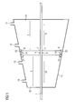
- Fig. 1 shows an abstract model of a reheat steam turbine. Centrally, a rotor shaft 1 is shown. A casing of the reheat steam turbine is basically separated into a left and a right compartment or module. The left compartment represents a high pressure chamber 12, and is building - together with all other components belonging to a high pressure chamber of a reheat steam turbine - the high pressure module.
- the right compartment represents a low pressure chamber 13, and may form - together with all other components belonging to a low pressure chamber of a reheat steam turbine - the low pressure module.
- the high pressure chamber 12 and the low pressure chamber 13 are separated by a common wall 6. Part of the high pressure chamber 12 is a high pressure inlet 14 through which superheated live steam at high temperature and high pressure from the boiler is led into the high pressure chamber 12.
- the high pressure portion 2 of the rotor assembly in a high pressure section 18 of the rotor shaft 1 there may be at least one high pressure rotor blade provided (not shown in figure 1 ).
- Superheated live steam makes thus the high pressure rotor blades 4 together with the rotor shaft 1 rotate. Thereby, the superheated live steam is expanding and losing temperature.
- the somewhat cooled down and expanded steam leaves the high pressure chamber 12 via high pressure outlet 15 or high pressure exhaust. From the high pressure exhaust the steam is led back into a reheat unit for re-heating and raising the temperature of the relative low pressure steam back to the original temperature.
- the reheated steam is then admitted into the low pressure chamber 13 through a low pressure inlet 16.
- a high pressure diaphragm may be provided between the two high pressure rotor blades. If more than two rotor blades stages are provided also more high pressure diaphragms could be provided between the rotor blades stages. It should be noted that none of the mentioned diaphragms are shown in Fig. 1 .
- the low pressure portion 2 of the rotor assembly in a low pressure section 19 of the rotor shaft 1 there may be at least one low pressure rotor blade provided (not shown in figure 1 ).
- the high pressure module there may be more than one low pressure rotor blade stage and one or more low pressure diaphragms provided.
- the high pressure chamber 12 and the low pressure chamber 13 are separated by a common wall 6.
- the common wall 6 extends radially from the rotor shaft 1 outwards. The common wall is thus facing the high pressure chamber 12 as well as the low pressure chamber 13, separating the two chambers or modules of the reheat steam turbine.
- the common wall 6 has also a shaft end 7 facing the rotor shaft 1 as well as an outer end facing a projection 20 of the casing 11 in a barrel design.
- the projection 20 extends from the inner side of the casing 11 surrounding the complete circumference of the casing 11.
- a rotor sealing 9 provided in the form of a common sealing strip, in particular a plurality of common sealing strips (not shown in Fig 1 ). It should be noted that there is no contact between the rotor shaft 1 and the rotor sealing 9 in order to allow a free rotatability of the rotor assembly.
- the rotor sealing 9 may also be carried out as a labyrinth or labyrinth sealing.
- a casing sealing 10 On the other end 8 of the common wall 6 there may be a casing sealing 10 provided. It may be provided in a groove of the common wall.
- This casing sealing 10 may be a piston ring, particularly a plurality of piston rings (not shown in Fig. 1 ), surrounding the complete common wall 6.
- the casing sealing 10 as well as the rotor sealing 9 are instrumental to separate - together with the common wall - the high pressure chamber 12 from the low pressure chamber 13. Because the casing 11 builds a common casing for the high pressure chamber 12 and the low pressure chamber 13, the common wall 6 separates at the same time the high pressure module from the low pressure module.
- the low pressure chamber / module may indeed be an intermediate-pressure chamber.
- an additional low pressure chamber may be coupled to the reheat steam turbine in a known manner.
- a gearbox for adjusting the rotational speed of the reheat steam turbine to a required rotational speed of a generator shaft of an electrical generator.
- a stopper 21 provided to which the common wall 6 may be attached.
- a stopper may be provided in the form of a diaphragm carrier.
- the diaphragm carrier may couple all available diaphragms and the common wall together.
- Such an assembly of all diaphragms and the common wall - together with a casing - may form a stator of the turbine.
- Fig. 2 shows an embodiment of the rotor assembly as well as a more detailed reheat steam turbine.
- the high pressure inlet 14, the high pressure outlet 15, the low pressure inlet, and the low pressure outlet 17 are shown.
- the low pressure inlet 16 is shown on the bottom of figure 2 .
- a casing 11 surrounds the high pressure chamber 12 and the low pressure chamber 13 in a barrel design. Recognizable are also high pressure rotor blades 4, low pressure rotor blades 5, the common wall 6, the rotor shaft 1 as well as diaphragms 22.
- Fig. 3 shows a magnification of a central part of Fig. 2 highlighting details of the common wall 6.
- the rotor shaft 1 is shown.
- the common wall is shown to have an L-shape.
- One leg of the L-shaped common wall 6 extends along the rotor shaft 1.
- three rotor sealings 9 in the form of common rotor stripes are shown. They are provided along the complete circumference of the rotor shaft 1 as well as inside a groove of a central hole of the common wall 6 through which the rotor shaft 1 is extending.
- the other leg of the L-shaped common wall 6 extends radially towards a projection 20 of the casing 11.
- a casing sealing 10, in particular a plurality of casing sealings 10, in the form of a piston ring are shown.
- the piston ring 10 extends throughout the complete circumference of the common wall 6 in a groove of the common wall 6 facing radially outwards.
- the leg of the common wall 6, extending radially, may comprise one or more separate common wall elements that may be fitted together in a known manner. It can clearly be seen that the rotor shaft 1, the rotor sealing 9, the common wall 6, and the casing sealing 10 together with the projection 20 of the casing 11, separate the high pressure chamber 12 and the low pressure chamber 13 of the reheat steam turbine.
- the live steam may enter the high pressure chamber 12 of the reheat steam turbine with a temperature in the range of about 380-460 °C, a pressure in the range of about 90-105 bar, and a volume in the range of about up to 1.7 m3/s for 50MW application.
- Other ranges should not be excluded, e.g., steam of about 500°C at the inlet of the high pressure inlet.
- the steam may leave the high pressure chamber 12 with a temperature in the range of about 300°C, a pressure in the range of a about 32 bar, and a volume in the range of about 4.2 m3/s.
- the reheated steam may enter the low pressure chamber 13 with a temperature in the range of about 400°C, a pressure in the range of about 30 bar, and a volume of about 5.3 m3/s. It should be noted again that these value are not limiting - they may in other embodiments vary to a wide extend.
Landscapes
- Engineering & Computer Science (AREA)
- Mechanical Engineering (AREA)
- General Engineering & Computer Science (AREA)
- Chemical & Material Sciences (AREA)
- Combustion & Propulsion (AREA)
- Turbine Rotor Nozzle Sealing (AREA)
Priority Applications (4)
| Application Number | Priority Date | Filing Date | Title |
|---|---|---|---|
| EP09014911A EP2333245A1 (fr) | 2009-12-01 | 2009-12-01 | Ensemble de rotor pour turbine à vapeur avec réchauffement |
| US12/956,038 US20110129335A1 (en) | 2009-12-01 | 2010-11-30 | Rotor Assembly for a Reheat Steam Turbine |
| BRPI1004690-9A BRPI1004690A2 (pt) | 2009-12-01 | 2010-11-30 | montagem de rotor para uma turbina a vapor de reaquecimento |
| CN2010105678573A CN102080574A (zh) | 2009-12-01 | 2010-12-01 | 用于再热式汽轮机的转子组件 |
Applications Claiming Priority (1)
| Application Number | Priority Date | Filing Date | Title |
|---|---|---|---|
| EP09014911A EP2333245A1 (fr) | 2009-12-01 | 2009-12-01 | Ensemble de rotor pour turbine à vapeur avec réchauffement |
Publications (1)
| Publication Number | Publication Date |
|---|---|
| EP2333245A1 true EP2333245A1 (fr) | 2011-06-15 |
Family
ID=41698315
Family Applications (1)
| Application Number | Title | Priority Date | Filing Date |
|---|---|---|---|
| EP09014911A Withdrawn EP2333245A1 (fr) | 2009-12-01 | 2009-12-01 | Ensemble de rotor pour turbine à vapeur avec réchauffement |
Country Status (4)
| Country | Link |
|---|---|
| US (1) | US20110129335A1 (fr) |
| EP (1) | EP2333245A1 (fr) |
| CN (1) | CN102080574A (fr) |
| BR (1) | BRPI1004690A2 (fr) |
Cited By (1)
| Publication number | Priority date | Publication date | Assignee | Title |
|---|---|---|---|---|
| CN102619961A (zh) * | 2012-03-12 | 2012-08-01 | 江苏金通灵流体机械科技股份有限公司 | 汽轮机用双输入高速齿轮变速箱 |
Families Citing this family (1)
| Publication number | Priority date | Publication date | Assignee | Title |
|---|---|---|---|---|
| CN108150434B (zh) * | 2018-01-17 | 2020-08-25 | 南通润邦重机有限公司 | 一种渐开线式进风多级涡轮风机 |
Citations (9)
| Publication number | Priority date | Publication date | Assignee | Title |
|---|---|---|---|---|
| US2547300A (en) * | 1949-05-26 | 1951-04-03 | Allis Chalmers Mfg Co | Diaphragm for reheat elastic fluid turbines |
| US2920867A (en) * | 1957-01-22 | 1960-01-12 | Westinghouse Electric Corp | Reheat turbine apparatus |
| GB846432A (en) * | 1958-06-09 | 1960-08-31 | Westinghouse Electric Corp | Improvements in or relating to elastic fluid turbines |
| JPS5620012U (fr) * | 1979-07-24 | 1981-02-21 | ||
| JPH02140404A (ja) * | 1988-11-22 | 1990-05-30 | Hitachi Ltd | 蒸気タービンの構造、及び蒸気タービン用蒸気発生系統、並びにその運用方法 |
| JPH048703U (fr) * | 1990-05-10 | 1992-01-27 | ||
| EP1744017A1 (fr) * | 2005-07-14 | 2007-01-17 | Siemens Aktiengesellschaft | Turbine combinée à vapeur et procédé de fonctionnement d'une turbine combinée à vapeur |
| JP2008202419A (ja) * | 2007-02-16 | 2008-09-04 | Mitsubishi Heavy Ind Ltd | 蒸気タービン車室構造 |
| EP2143888A2 (fr) * | 2008-07-11 | 2010-01-13 | Kabushiki Kaisha Toshiba | Turbine à vapeur et procédé de refroidissement de turbine à vapeur |
Family Cites Families (2)
| Publication number | Priority date | Publication date | Assignee | Title |
|---|---|---|---|---|
| JP2001221012A (ja) * | 2000-02-10 | 2001-08-17 | Toshiba Corp | 蒸気タービンおよび発電設備 |
| GB0814314D0 (en) * | 2008-08-06 | 2008-09-10 | Rolls Royce Plc | A Method of assembling a multi-stage turbine or compressor |
-
2009
- 2009-12-01 EP EP09014911A patent/EP2333245A1/fr not_active Withdrawn
-
2010
- 2010-11-30 BR BRPI1004690-9A patent/BRPI1004690A2/pt not_active IP Right Cessation
- 2010-11-30 US US12/956,038 patent/US20110129335A1/en not_active Abandoned
- 2010-12-01 CN CN2010105678573A patent/CN102080574A/zh active Pending
Patent Citations (9)
| Publication number | Priority date | Publication date | Assignee | Title |
|---|---|---|---|---|
| US2547300A (en) * | 1949-05-26 | 1951-04-03 | Allis Chalmers Mfg Co | Diaphragm for reheat elastic fluid turbines |
| US2920867A (en) * | 1957-01-22 | 1960-01-12 | Westinghouse Electric Corp | Reheat turbine apparatus |
| GB846432A (en) * | 1958-06-09 | 1960-08-31 | Westinghouse Electric Corp | Improvements in or relating to elastic fluid turbines |
| JPS5620012U (fr) * | 1979-07-24 | 1981-02-21 | ||
| JPH02140404A (ja) * | 1988-11-22 | 1990-05-30 | Hitachi Ltd | 蒸気タービンの構造、及び蒸気タービン用蒸気発生系統、並びにその運用方法 |
| JPH048703U (fr) * | 1990-05-10 | 1992-01-27 | ||
| EP1744017A1 (fr) * | 2005-07-14 | 2007-01-17 | Siemens Aktiengesellschaft | Turbine combinée à vapeur et procédé de fonctionnement d'une turbine combinée à vapeur |
| JP2008202419A (ja) * | 2007-02-16 | 2008-09-04 | Mitsubishi Heavy Ind Ltd | 蒸気タービン車室構造 |
| EP2143888A2 (fr) * | 2008-07-11 | 2010-01-13 | Kabushiki Kaisha Toshiba | Turbine à vapeur et procédé de refroidissement de turbine à vapeur |
Cited By (1)
| Publication number | Priority date | Publication date | Assignee | Title |
|---|---|---|---|---|
| CN102619961A (zh) * | 2012-03-12 | 2012-08-01 | 江苏金通灵流体机械科技股份有限公司 | 汽轮机用双输入高速齿轮变速箱 |
Also Published As
| Publication number | Publication date |
|---|---|
| BRPI1004690A2 (pt) | 2013-03-12 |
| CN102080574A (zh) | 2011-06-01 |
| US20110129335A1 (en) | 2011-06-02 |
Similar Documents
| Publication | Publication Date | Title |
|---|---|---|
| US6715294B2 (en) | Combined open cycle system for thermal energy conversion | |
| US20090136337A1 (en) | Method and Apparatus for Improved Reduced Load Operation of Steam Turbines | |
| US20080245071A1 (en) | Thermal power plant | |
| US9856754B1 (en) | Cascaded recompression closed brayton cycle system | |
| US8418467B2 (en) | System including feedwater heater for extracting heat from low pressure steam turbine | |
| WO1997031192A1 (fr) | Compresseur axial a refroidissement intermediaire integral et son utilisation dans les centrales electriques | |
| US20130097994A1 (en) | Multi-fluid turbine engine | |
| US6971842B2 (en) | Low pressure steam turbine exhaust hood | |
| KR20140116121A (ko) | 랭킨 사이클에서 유기 작동 유체를 팽창시키는 방법 및 터빈 | |
| US8376687B2 (en) | System and method for cooling steam turbine rotors | |
| RU2522228C2 (ru) | Способ и система для регулирования протечки газа в турбине и турбина | |
| US9149865B2 (en) | Method for manufacturing micro gas turbine | |
| EP2333245A1 (fr) | Ensemble de rotor pour turbine à vapeur avec réchauffement | |
| US11359520B2 (en) | Steam turbine facility and combined cycle plant | |
| US8899909B2 (en) | Systems and methods for steam turbine wheel space cooling | |
| US11352912B2 (en) | Steam turbine facility and combined cycle plant | |
| EP2333246B1 (fr) | Turbine à réchauffage avec paroi de séparation | |
| Kasilov et al. | Cogeneration steam turbines from Siemens: New solutions | |
| US8863492B2 (en) | Combined cycle power plant with split compressor | |
| Uematsu et al. | Topping recuperation cycle for hydrogen combustion turbine in WE-NET | |
| Rahman et al. | IMPROVE THE EFFICIENCY OF COMBINED CYCLE POWER PLANT | |
| KR101704306B1 (ko) | 레디얼 터빈을 이용한 폐열 회수 터빈 시스템 | |
| Wittchow | 4 Steam turbines: 3 Fossil-fueled power plants | |
| Ashmore | Powering up for 2000. |
Legal Events
| Date | Code | Title | Description |
|---|---|---|---|
| PUAI | Public reference made under article 153(3) epc to a published international application that has entered the european phase |
Free format text: ORIGINAL CODE: 0009012 |
|
| AK | Designated contracting states |
Kind code of ref document: A1 Designated state(s): AT BE BG CH CY CZ DE DK EE ES FI FR GB GR HR HU IE IS IT LI LT LU LV MC MK MT NL NO PL PT RO SE SI SK SM TR |
|
| AX | Request for extension of the european patent |
Extension state: AL BA RS |
|
| 17P | Request for examination filed |
Effective date: 20111212 |
|
| RAP1 | Party data changed (applicant data changed or rights of an application transferred) |
Owner name: SIEMENS AKTIENGESELLSCHAFT |
|
| STAA | Information on the status of an ep patent application or granted ep patent |
Free format text: STATUS: THE APPLICATION IS DEEMED TO BE WITHDRAWN |
|
| 18D | Application deemed to be withdrawn |
Effective date: 20150701 |