EP2333265A1 - Collecteur de gaz d'échappement doté d'un déflecteur - Google Patents
Collecteur de gaz d'échappement doté d'un déflecteur Download PDFInfo
- Publication number
- EP2333265A1 EP2333265A1 EP10014314A EP10014314A EP2333265A1 EP 2333265 A1 EP2333265 A1 EP 2333265A1 EP 10014314 A EP10014314 A EP 10014314A EP 10014314 A EP10014314 A EP 10014314A EP 2333265 A1 EP2333265 A1 EP 2333265A1
- Authority
- EP
- European Patent Office
- Prior art keywords
- exhaust manifold
- openings
- motor flange
- manifold according
- guide plate
- Prior art date
- Legal status (The legal status is an assumption and is not a legal conclusion. Google has not performed a legal analysis and makes no representation as to the accuracy of the status listed.)
- Granted
Links
Images
Classifications
-
- F—MECHANICAL ENGINEERING; LIGHTING; HEATING; WEAPONS; BLASTING
- F01—MACHINES OR ENGINES IN GENERAL; ENGINE PLANTS IN GENERAL; STEAM ENGINES
- F01N—GAS-FLOW SILENCERS OR EXHAUST APPARATUS FOR MACHINES OR ENGINES IN GENERAL; GAS-FLOW SILENCERS OR EXHAUST APPARATUS FOR INTERNAL-COMBUSTION ENGINES
- F01N13/00—Exhaust or silencing apparatus characterised by constructional features
- F01N13/08—Other arrangements or adaptations of exhaust conduits
- F01N13/10—Other arrangements or adaptations of exhaust conduits of exhaust manifolds
- F01N13/102—Other arrangements or adaptations of exhaust conduits of exhaust manifolds having thermal insulation
-
- F—MECHANICAL ENGINEERING; LIGHTING; HEATING; WEAPONS; BLASTING
- F01—MACHINES OR ENGINES IN GENERAL; ENGINE PLANTS IN GENERAL; STEAM ENGINES
- F01N—GAS-FLOW SILENCERS OR EXHAUST APPARATUS FOR MACHINES OR ENGINES IN GENERAL; GAS-FLOW SILENCERS OR EXHAUST APPARATUS FOR INTERNAL-COMBUSTION ENGINES
- F01N13/00—Exhaust or silencing apparatus characterised by constructional features
- F01N13/08—Other arrangements or adaptations of exhaust conduits
- F01N13/10—Other arrangements or adaptations of exhaust conduits of exhaust manifolds
-
- F—MECHANICAL ENGINEERING; LIGHTING; HEATING; WEAPONS; BLASTING
- F01—MACHINES OR ENGINES IN GENERAL; ENGINE PLANTS IN GENERAL; STEAM ENGINES
- F01N—GAS-FLOW SILENCERS OR EXHAUST APPARATUS FOR MACHINES OR ENGINES IN GENERAL; GAS-FLOW SILENCERS OR EXHAUST APPARATUS FOR INTERNAL-COMBUSTION ENGINES
- F01N13/00—Exhaust or silencing apparatus characterised by constructional features
- F01N13/18—Construction facilitating manufacture, assembly, or disassembly
- F01N13/1872—Construction facilitating manufacture, assembly, or disassembly the assembly using stamp-formed parts or otherwise deformed sheet-metal
Definitions
- the present invention relates to an exhaust manifold for mounting by means of a motor flange on a cylinder head of an internal combustion engine having at least two cylinders in series, wherein the exhaust manifold is made as a thin-walled sheet metal component in shell construction with an upper shell and a lower shell.
- Exhaust manifolds can be made in a known manner from cast steel or built from individually welded together steel sheets or pipe fittings.
- the advantage of Stahlgusskrümmern is that complicated geometries are relatively inexpensive to produce.
- the weight of cast steel elbows is generally higher than that of welded sheet steel constructions.
- cast steel manifolds have higher thermal inertia than welded exhaust manifolds.
- Welded exhaust manifolds can only be produced with increased complexity and thus higher costs in complex geometries. However, they have a lower heat capacity due to their lower weight. That's an advantage.
- the engines are often charged by a compressor, usually a turbocharger.
- An increase in the efficiency of the turbocharger has an effect on the increase in efficiency of the internal combustion engine.
- Object of the present invention is therefore to provide an exhaust manifold, which allows a low heat capacity and cost manufacturability and an increase in efficiency of the internal combustion engine.
- the exhaust manifold has a motor flange by means of which it is attached to a cylinder head of an internal combustion engine having at least two cylinders in series.
- the exhaust manifold should be made as a thin-walled sheet metal component in shell construction with an upper shell and a lower shell.
- Such an exhaust manifold is inventively characterized in that in the exhaust manifold on the cylinder side, in particular a one-piece baffle is used, which separates the interior of the exhaust manifold from the engine flange.
- the engine flange is usually designed as a cast steel product, which gives the exhaust manifold a high thermal inertia.
- the mass of the motor flange is not readily reducible because it has a supporting function for the exhaust assembly and also subject to high thermal stresses. Therefore, the invention is the way to separate the flange area by area of the interior of the exhaust manifold. However, this is not done by the fact that the sheet metal shells of the exhaust manifold only partially, namely only in the region of the outlet channel openings, with the motor flange rather, a baffle inside the exhaust manifold takes over the task of shielding.
- baffle Depending on the design of the baffle is influenced by the course of the flow path of the exhaust gas within the exhaust manifold, which in turn has a positive effect on the light-off behavior of a downstream turbocharger, which increases the overall efficiency of the internal combustion engine.
- the design of thin-walled sheet metal components leads to a low heat capacity and thus to a low heat dissipation, so that a downstream catalyst faster reaches the required operating temperature and thus exhaust limits can be better met.
- baffle In a first development, only the interior of the exhaust manifold facing surfaces of the engine flange are covered by a baffle. As a result, the heat energy contained in the exhaust gas is only partially possible to make a heat input into the motor flange. It is quite possible within the scope of the invention to provide a plurality of individual baffles, which are each arranged between the individual outlet channel openings of the motor flange and are individually matched to the flow conditions prevailing in the region of these outlet channel openings.
- the guide plate has openings in the region of outlet channel openings of the motor flange.
- the exhaust gas thus passes through the exhaust ports of the cylinder head and through the exhaust port openings of the cylinder head Engine flange directly into the exhaust manifold.
- the outlet channel openings in the baffle make it clear that the baffle extends around the openings.
- the baffle may accordingly also have four openings, so that in total only one single baffle has to be produced, which is position-oriented or fixed on the sheet metal shells of the exhaust manifold or on the motor flange.
- the guide plate has a collar in the region of its openings, which extend into the outlet channel openings.
- sliding seats are formed between the collar and the outlet channel openings of the motor flange.
- the baffle consists of a thin-walled sheet metal component, whereas the motor flange consists of a thick-walled cast material.
- the baffle is exposed directly to the hot exhaust gas flow, whereas the engine flange is exposed to ambient temperature. Especially in cold start behavior or Even at full load, the different thermal expansion of the materials and designs is noticeable. Any distortions that occur due to different thermal expansions are compensated by a sliding seat, so that a better durability of the baffle is given.
- the guide plate is at least partially spaced from the motor flange in a region between the openings.
- This offers on the one hand the advantage that in the space spaced a cavity is formed, which thermally isolates the motor flange from the baffle.
- the cavity may also be filled with exhaust gas, which, however, due to the gas inertia has a lower temperature and possibly a lower pressure ratio than the exhaust gas in the interior of the exhaust manifold. Even if the cavity is filled with exhaust gas, this does not mean that the engine flange is not separated from the interior of the baffle.
- a hermetic, in particular gas-tight shielding which can only be realized with a particularly careful connection of the baffle with the upper shell and the lower shell. Rather, a shield is sought in the sense that the vast majority of the exhaust gas does not come into contact with the motor flange solely by the flow velocity and flow direction, which by pressure equalization between the interior of the exhaust manifold and the cavities separated therefrom, which also within the exhaust manifold There is a slight gas exchange, but essentially does not go beyond the said pressure equalization.
- the advantages of the invention are thus achieved even if the baffle is not connected in a gastight manner with the upper shell and the lower shell of the exhaust manifold, although a substantial gas-tightness is sought.
- Another advantage resulting from the cavities is that the interior of the exhaust manifold is reduced in volume. Especially with regard to the response of the turbine wheel of a turbocharger is a small volume of the interior of the exhaust manifold of advantage. An escaping gas shock from a cylinder in the form of an exhaust stroke is thus forwarded as directly as possible to the turbine blades. A reduction of the flow velocity due to an increasing volume of the exhaust manifold is thereby counteracted.
- areas of the guide plate between the openings are preferably formed arcuate.
- the volume of the interior of the exhaust manifold is purposefully reduced by the arc shape with respect to the exhaust passage.
- an arcuate geometry is to be understood as a geometry shape in which the greatest distance to the motor flange is located centrally between the two outlet channel openings and the distance to the outlet channel openings is reduced so that there is contact at the end with the outlet openings.
- a triangular, trapezoidal or other shape is conceivable under an arcuate design.
- gentle transitions are preferred, so that the arc is actually a circular arc or an elliptical section or has another shape composed of curved sections.
- the shape must be optimally adapted to the internal combustion engine.
- the exhaust back pressure in the exhaust system is to be observed.
- Another influencing factor in the choice of the shape of the spacing of the guide plate from the engine flange between the outlet channel openings is, for example, the arrangement of a further flange for connecting an exhaust pipe or two flanges or an exhaust gas recirculation.
- the arcuate area must therefore be identical in any case between all adjacent outlet openings.
- the arcuate areas can be completely different from each other in their concrete embodiment. Decisive is their function to shield the engine flange and keep the exhaust or the heat input to form a cavity away from the motor flange while adjusting the flow cross sections.
- the baffle is located on the upper shell and the lower shell circumferentially in a contact area. Due to the circumferential concern of the engine flange of the interior of the exhaust manifold, which is formed by upper, lower shell and baffle separated.
- the contact area can be formed both non-gas-tight and gas-tight.
- the contact area is formed parallel to a respectively corresponding surface of the upper and lower shell.
- a substantially peripheral flanged edge is formed in the contact region, wherein the direction of the flare facing the engine flange or pointing away from the engine flange is formed.
- the crimping edge increases the rigidity of the baffle against the high pressures occurring in the exhaust manifold interior.
- the bead gives the entire exhaust manifold a higher rigidity against pressure and vibration, which affects the durability of the exhaust manifold. It is also possible in the course of the invention to attach a sealing compound to the peripheral flanged edge, so that the guide plate in the contact area is circumferentially sealed gas-tight.
- the baffle in the contact area is at least partially fixedly connected to the upper shell and the lower shell, wherein the compound is particularly preferably made by means of material connection.
- a connection by thermal joining is feasible.
- Thermal joining offers the advantage that the exhaust manifold can be produced cost-effectively, but it also guarantees a particularly high durability.
- the durability is important because different temperature-dependent expansions of the individual components occur. The thermal strains cause stresses, especially in the area of welds. Due to the vibration loads occurring in the exhaust area, it is essential to ensure that solve any components, which could lead to disturbing rattling noises in addition to a functional impairment.
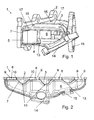
- FIG. 1 1 shows a perspective sectional view of an exhaust manifold 1 comprising a motor flange 2, an upper shell 3 and a lower shell 4.
- a baffle 5 is inserted into the inner space 6 of the exhaust manifold 1 thus formed.
- the guide plate 5 separates the interior 6 of the exhaust manifold 1 from surfaces 7 of the motor flange 2.
- FIG. 2 shows a longitudinal section in a plan view of an exhaust manifold 1 according to the invention.
- the baffle 5 in this case has openings 8, which extend into outlet channel openings 9 of the motor flange 2.
- the openings 8 of the baffle 5 have to collar 10.
- the baffle 5 separates in areas between the openings 8, the surfaces 7 of the motor flange 2 from the interior 6 of the exhaust manifold 1.
- the areas 11 between the openings 8 are preferably arcuate educated.
- the central arcuate region on the image plane has a greater extent into the interior 6 than the arcuate regions lying on the edge.
- the respective outer arcuate region can also be made flatter because the housing of the exhaust manifold 1 has a smaller cross section in its end regions than in its central region where the outlet flange 14 is located, to which the collected exhaust gas is supplied.
- FIG. 1 a flange 15 of an exhaust gas recirculation can be seen.
- the exhaust flange 14 and the flange 15 for exhaust gas recirculation are in this embodiment at an angle to each other, wherein the flange 15 is disposed in the transition region of the upper shell 3 to the lower shell 4.
- the outlet flange 14 is located in the region of the lower shell 4 in this exemplary embodiment.
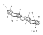
- FIG. 1 It should also be noted that there are two recesses 16 in the area of the upper shell 3. These recesses serve to fix the baffle 5, namely by welding in the region of the recesses 16. The welding takes place with flanged edges 13 of the baffle 5. The flanged edges 13 belong to a contact area 12 which runs parallel to the corresponding surfaces of the upper and lower shell 3, 4.
- FIG. 1 It can be seen that the upper and lower shell 3, 4 are not flat at their opposite outer sides, but have beads 17, which are necessary for mounting technical reasons for screwing the engine flange 2 to an internal combustion engine, not shown.
- the flanged edge 13 is adapted in its course to the beads as well as to the remaining inner contour of the upper and lower shell 3, 4 in order to produce the highest possible gas tightness.
- the recesses 16 are located between the beads. These welds, so to speak, form the fixed bearing of the baffle 5, which thereby projects into the individual outlet channel openings 9 of the motor flange 2, forming a sliding seat.
Landscapes
- Engineering & Computer Science (AREA)
- Chemical & Material Sciences (AREA)
- Combustion & Propulsion (AREA)
- Mechanical Engineering (AREA)
- General Engineering & Computer Science (AREA)
- Exhaust Silencers (AREA)
Applications Claiming Priority (1)
| Application Number | Priority Date | Filing Date | Title |
|---|---|---|---|
| DE102009058047A DE102009058047A1 (de) | 2009-12-14 | 2009-12-14 | Abgaskrümmer mit Leitblech |
Publications (2)
| Publication Number | Publication Date |
|---|---|
| EP2333265A1 true EP2333265A1 (fr) | 2011-06-15 |
| EP2333265B1 EP2333265B1 (fr) | 2011-11-02 |
Family
ID=43735839
Family Applications (1)
| Application Number | Title | Priority Date | Filing Date |
|---|---|---|---|
| EP10014314A Not-in-force EP2333265B1 (fr) | 2009-12-14 | 2010-11-05 | Collecteur de gaz d'échappement doté d'un déflecteur |
Country Status (5)
| Country | Link |
|---|---|
| US (1) | US8549851B2 (fr) |
| EP (1) | EP2333265B1 (fr) |
| JP (1) | JP2011122594A (fr) |
| AT (1) | ATE531912T1 (fr) |
| DE (1) | DE102009058047A1 (fr) |
Families Citing this family (12)
| Publication number | Priority date | Publication date | Assignee | Title |
|---|---|---|---|---|
| DE102008047448B4 (de) * | 2008-09-16 | 2020-09-24 | Bayerische Motoren Werke Aktiengesellschaft | Abgasturbolader |
| DE102011050506B4 (de) | 2011-05-19 | 2013-04-18 | Benteler Automobiltechnik Gmbh | Abgasturbolader |
| DE102012009090A1 (de) | 2012-05-09 | 2013-11-14 | Benteler Automobiltechnik Gmbh | Anbindung eines doppelwandigen Turboladergehäuses |
| DE102013109446B4 (de) | 2013-08-30 | 2015-11-26 | Benteler Automobiltechnik Gmbh | Abgaskrümmer mit Isolationshülse |
| DE102013111957B4 (de) * | 2013-10-30 | 2016-12-01 | Benteler Automobiltechnik Gmbh | Abgasleitungseinheit eines Kraftfahrzeugs |
| DE102014103820A1 (de) | 2014-03-20 | 2015-09-24 | Benteler Automobiltechnik Gmbh | Abgaskrümmer für eine Abgasanlage eines Verbrennungsmotors |
| DE102014103809A1 (de) | 2014-03-20 | 2015-12-03 | Benteler Automobiltechnik Gmbh | Abgaskrümmer für eine Abgasanlage eines Verbrennungsmotors |
| DE102014105656B4 (de) | 2014-04-22 | 2017-02-02 | Benteler Automobiltechnik Gmbh | Abgaskrümmer |
| WO2016164020A1 (fr) * | 2015-04-09 | 2016-10-13 | Cummins Inc. | Nervures de renforcement de collecteur d'échappement |
| GB2532546B (en) * | 2015-08-19 | 2017-02-22 | Litchfield Iain | Exhaust manifold |
| US10544703B2 (en) | 2017-01-30 | 2020-01-28 | Garrett Transportation I Inc. | Sheet metal turbine housing with cast core |
| US11732729B2 (en) | 2021-01-26 | 2023-08-22 | Garrett Transportation I Inc | Sheet metal turbine housing |
Citations (4)
| Publication number | Priority date | Publication date | Assignee | Title |
|---|---|---|---|---|
| EP0717179A1 (fr) * | 1994-12-16 | 1996-06-19 | Firma J. Eberspächer | Collecteur d'échappement isolé par couche d'air |
| EP1172534A2 (fr) * | 2000-07-15 | 2002-01-16 | J. Eberspächer GmbH & Co. | Collecteur d'échappement |
| WO2009091540A1 (fr) * | 2008-01-14 | 2009-07-23 | Metaldyne Company Llc | Joint bicouche soudé à un rebord |
| US20090282820A1 (en) * | 2008-04-07 | 2009-11-19 | Hill Jr Frederick B | Exhaust manifold with hybrid construction and method |
Family Cites Families (15)
| Publication number | Priority date | Publication date | Assignee | Title |
|---|---|---|---|---|
| US4537027A (en) * | 1983-11-21 | 1985-08-27 | Apx Group, Inc. | Hybrid exhaust manifold |
| JPS63158527A (ja) | 1986-08-25 | 1988-07-01 | Canon Inc | 光学変調器 |
| US4777708A (en) * | 1987-03-17 | 1988-10-18 | Ap Industries, Inc. | Method for manufacturing an exhaust manifold |
| JPH041292Y2 (fr) * | 1987-04-04 | 1992-01-17 | ||
| US4850189A (en) * | 1987-10-14 | 1989-07-25 | Arvin Industries, Inc. | Manifold baffle system |
| DE59501301D1 (de) * | 1995-09-28 | 1998-02-19 | Benteler Werke Ag | Abgaskrümmer |
| US5784881A (en) | 1996-01-11 | 1998-07-28 | Hitachi Metals, Ltd. | Multi-part exhaust manifold assembly with welded connections |
| JPH09296725A (ja) * | 1996-01-11 | 1997-11-18 | Hitachi Metals Ltd | 分割型排気マニホルド |
| JP3344210B2 (ja) * | 1996-05-27 | 2002-11-11 | 日産自動車株式会社 | 二重管エキゾーストマニホールド |
| JP4283927B2 (ja) * | 1999-03-02 | 2009-06-24 | フタバ産業株式会社 | エギゾーストマニホルド |
| ATE288539T1 (de) * | 1999-08-05 | 2005-02-15 | Hans A Haerle | Abgaskrümmer |
| DE10341868B4 (de) * | 2003-09-09 | 2005-12-22 | Härle, Hans A. | Vorrichtung zur Halterung wenigstens eines Abgasreinigungselements |
| DE10352960B4 (de) | 2003-11-13 | 2006-06-14 | Benteler Automobiltechnik Gmbh | Gehäuseanordnung für den Turbolader einer Brennkraftmaschine |
| DE10359073B4 (de) * | 2003-12-17 | 2006-03-02 | Daimlerchrysler Ag | Abgaskrümmer |
| DE102004025407A1 (de) * | 2004-05-24 | 2005-12-22 | Arvin Technologies, Inc., Troy | Krümmer für einen Mehrzylinder-Verbrennungsmotor |
-
2009
- 2009-12-14 DE DE102009058047A patent/DE102009058047A1/de not_active Withdrawn
-
2010
- 2010-11-05 EP EP10014314A patent/EP2333265B1/fr not_active Not-in-force
- 2010-11-05 AT AT10014314T patent/ATE531912T1/de active
- 2010-12-10 JP JP2010275784A patent/JP2011122594A/ja active Pending
- 2010-12-14 US US12/967,470 patent/US8549851B2/en not_active Expired - Fee Related
Patent Citations (4)
| Publication number | Priority date | Publication date | Assignee | Title |
|---|---|---|---|---|
| EP0717179A1 (fr) * | 1994-12-16 | 1996-06-19 | Firma J. Eberspächer | Collecteur d'échappement isolé par couche d'air |
| EP1172534A2 (fr) * | 2000-07-15 | 2002-01-16 | J. Eberspächer GmbH & Co. | Collecteur d'échappement |
| WO2009091540A1 (fr) * | 2008-01-14 | 2009-07-23 | Metaldyne Company Llc | Joint bicouche soudé à un rebord |
| US20090282820A1 (en) * | 2008-04-07 | 2009-11-19 | Hill Jr Frederick B | Exhaust manifold with hybrid construction and method |
Also Published As
| Publication number | Publication date |
|---|---|
| EP2333265B1 (fr) | 2011-11-02 |
| DE102009058047A1 (de) | 2011-06-16 |
| US8549851B2 (en) | 2013-10-08 |
| US20110308238A1 (en) | 2011-12-22 |
| ATE531912T1 (de) | 2011-11-15 |
| JP2011122594A (ja) | 2011-06-23 |
Similar Documents
| Publication | Publication Date | Title |
|---|---|---|
| EP2333265B1 (fr) | Collecteur de gaz d'échappement doté d'un déflecteur | |
| EP2267285B1 (fr) | Module d'échappement | |
| DE10061846B4 (de) | Abgasturbolader für eine Brennkraftmaschine | |
| DE102009011379B4 (de) | Abgasbaugruppe | |
| DE10307028B3 (de) | Anordnung zur Überführung der Abgase eines Verbrennungsmotors in eine Abgasleitung | |
| EP2634393B1 (fr) | Module de fonctionnement doté d'une turbosoufflante de gaz d'échappement et d'un collecteur de gaz d'échappement | |
| WO2010003537A2 (fr) | Boîtier de turbine pour turbocompresseur à gaz d'échappement d'un moteur à combustion interne | |
| EP3339601B1 (fr) | Ensemble turbocompresseur | |
| EP1389267B1 (fr) | Collecteur d'echappement | |
| EP2859190B1 (fr) | Carter de turbine pour turbocompresseur à gaz d'echappement | |
| EP0849445B1 (fr) | Collecteur d'échappement et procédé pour sa fabrication | |
| DE3631312C1 (de) | Einrichtung zur Halterung von Abgasleitungen | |
| EP3001004B1 (fr) | Collecteur de gaz d'echappement | |
| DE102008049091A1 (de) | Verfahren zum Betreiben einer Brennkraftmaschine mit acht Zylindern und Brennkraftmaschine | |
| DE102009010311A1 (de) | Ladeeinrichtung | |
| DE102016116995A1 (de) | Abgasanlage mit verbesserter thermischer Belastbarkeit | |
| DE102014105656B4 (de) | Abgaskrümmer | |
| DE102010018087A1 (de) | Abgassystem für eine Brennkraftmaschine | |
| EP3918190B1 (fr) | Dispositif pour l'évacuation de gaz d'échappement pour un moteur à combustion interne | |
| DE102008050961B4 (de) | Abgaskrümmeranordnung | |
| EP1691049B1 (fr) | Collecteur d'échappement à double paroi | |
| DE112017003009T5 (de) | Fahrzeugabgassystem | |
| DE102008013767A1 (de) | Abgasturboladeranordnung | |
| EP2961957B1 (fr) | Module d'admission d'air | |
| DE102008049096A1 (de) | Abgasanlage einer Verbrennungskraftmaschine |
Legal Events
| Date | Code | Title | Description |
|---|---|---|---|
| PUAI | Public reference made under article 153(3) epc to a published international application that has entered the european phase |
Free format text: ORIGINAL CODE: 0009012 |
|
| 17P | Request for examination filed |
Effective date: 20110413 |
|
| AK | Designated contracting states |
Kind code of ref document: A1 Designated state(s): AL AT BE BG CH CY CZ DE DK EE ES FI FR GB GR HR HU IE IS IT LI LT LU LV MC MK MT NL NO PL PT RO RS SE SI SK SM TR |
|
| AX | Request for extension of the european patent |
Extension state: BA ME |
|
| GRAP | Despatch of communication of intention to grant a patent |
Free format text: ORIGINAL CODE: EPIDOSNIGR1 |
|
| GRAS | Grant fee paid |
Free format text: ORIGINAL CODE: EPIDOSNIGR3 |
|
| GRAA | (expected) grant |
Free format text: ORIGINAL CODE: 0009210 |
|
| AK | Designated contracting states |
Kind code of ref document: B1 Designated state(s): AL AT BE BG CH CY CZ DE DK EE ES FI FR GB GR HR HU IE IS IT LI LT LU LV MC MK MT NL NO PL PT RO RS SE SI SK SM TR |
|
| REG | Reference to a national code |
Ref country code: GB Ref legal event code: FG4D Free format text: NOT ENGLISH |
|
| REG | Reference to a national code |
Ref country code: CH Ref legal event code: EP |
|
| REG | Reference to a national code |
Ref country code: IE Ref legal event code: FG4D |
|
| REG | Reference to a national code |
Ref country code: DE Ref legal event code: R096 Ref document number: 502010000189 Country of ref document: DE Effective date: 20120112 |
|
| REG | Reference to a national code |
Ref country code: NL Ref legal event code: VDEP Effective date: 20111102 |
|
| LTIE | Lt: invalidation of european patent or patent extension |
Effective date: 20111102 |
|
| PG25 | Lapsed in a contracting state [announced via postgrant information from national office to epo] |
Ref country code: LT Free format text: LAPSE BECAUSE OF FAILURE TO SUBMIT A TRANSLATION OF THE DESCRIPTION OR TO PAY THE FEE WITHIN THE PRESCRIBED TIME-LIMIT Effective date: 20111102 Ref country code: NO Free format text: LAPSE BECAUSE OF FAILURE TO SUBMIT A TRANSLATION OF THE DESCRIPTION OR TO PAY THE FEE WITHIN THE PRESCRIBED TIME-LIMIT Effective date: 20120202 Ref country code: IS Free format text: LAPSE BECAUSE OF FAILURE TO SUBMIT A TRANSLATION OF THE DESCRIPTION OR TO PAY THE FEE WITHIN THE PRESCRIBED TIME-LIMIT Effective date: 20120302 |
|
| PG25 | Lapsed in a contracting state [announced via postgrant information from national office to epo] |
Ref country code: PL Free format text: LAPSE BECAUSE OF FAILURE TO SUBMIT A TRANSLATION OF THE DESCRIPTION OR TO PAY THE FEE WITHIN THE PRESCRIBED TIME-LIMIT Effective date: 20111102 Ref country code: PT Free format text: LAPSE BECAUSE OF FAILURE TO SUBMIT A TRANSLATION OF THE DESCRIPTION OR TO PAY THE FEE WITHIN THE PRESCRIBED TIME-LIMIT Effective date: 20120302 Ref country code: NL Free format text: LAPSE BECAUSE OF FAILURE TO SUBMIT A TRANSLATION OF THE DESCRIPTION OR TO PAY THE FEE WITHIN THE PRESCRIBED TIME-LIMIT Effective date: 20111102 Ref country code: SE Free format text: LAPSE BECAUSE OF FAILURE TO SUBMIT A TRANSLATION OF THE DESCRIPTION OR TO PAY THE FEE WITHIN THE PRESCRIBED TIME-LIMIT Effective date: 20111102 Ref country code: HR Free format text: LAPSE BECAUSE OF FAILURE TO SUBMIT A TRANSLATION OF THE DESCRIPTION OR TO PAY THE FEE WITHIN THE PRESCRIBED TIME-LIMIT Effective date: 20111102 Ref country code: GR Free format text: LAPSE BECAUSE OF FAILURE TO SUBMIT A TRANSLATION OF THE DESCRIPTION OR TO PAY THE FEE WITHIN THE PRESCRIBED TIME-LIMIT Effective date: 20120203 Ref country code: LV Free format text: LAPSE BECAUSE OF FAILURE TO SUBMIT A TRANSLATION OF THE DESCRIPTION OR TO PAY THE FEE WITHIN THE PRESCRIBED TIME-LIMIT Effective date: 20111102 Ref country code: SI Free format text: LAPSE BECAUSE OF FAILURE TO SUBMIT A TRANSLATION OF THE DESCRIPTION OR TO PAY THE FEE WITHIN THE PRESCRIBED TIME-LIMIT Effective date: 20111102 |
|
| REG | Reference to a national code |
Ref country code: IE Ref legal event code: FD4D |
|
| PG25 | Lapsed in a contracting state [announced via postgrant information from national office to epo] |
Ref country code: CY Free format text: LAPSE BECAUSE OF FAILURE TO SUBMIT A TRANSLATION OF THE DESCRIPTION OR TO PAY THE FEE WITHIN THE PRESCRIBED TIME-LIMIT Effective date: 20111102 Ref country code: RS Free format text: LAPSE BECAUSE OF FAILURE TO SUBMIT A TRANSLATION OF THE DESCRIPTION OR TO PAY THE FEE WITHIN THE PRESCRIBED TIME-LIMIT Effective date: 20111102 Ref country code: MC Free format text: LAPSE BECAUSE OF NON-PAYMENT OF DUE FEES Effective date: 20111130 |
|
| PG25 | Lapsed in a contracting state [announced via postgrant information from national office to epo] |
Ref country code: DK Free format text: LAPSE BECAUSE OF FAILURE TO SUBMIT A TRANSLATION OF THE DESCRIPTION OR TO PAY THE FEE WITHIN THE PRESCRIBED TIME-LIMIT Effective date: 20111102 Ref country code: BG Free format text: LAPSE BECAUSE OF FAILURE TO SUBMIT A TRANSLATION OF THE DESCRIPTION OR TO PAY THE FEE WITHIN THE PRESCRIBED TIME-LIMIT Effective date: 20120202 Ref country code: CZ Free format text: LAPSE BECAUSE OF FAILURE TO SUBMIT A TRANSLATION OF THE DESCRIPTION OR TO PAY THE FEE WITHIN THE PRESCRIBED TIME-LIMIT Effective date: 20111102 Ref country code: SK Free format text: LAPSE BECAUSE OF FAILURE TO SUBMIT A TRANSLATION OF THE DESCRIPTION OR TO PAY THE FEE WITHIN THE PRESCRIBED TIME-LIMIT Effective date: 20111102 Ref country code: EE Free format text: LAPSE BECAUSE OF FAILURE TO SUBMIT A TRANSLATION OF THE DESCRIPTION OR TO PAY THE FEE WITHIN THE PRESCRIBED TIME-LIMIT Effective date: 20111102 Ref country code: IE Free format text: LAPSE BECAUSE OF FAILURE TO SUBMIT A TRANSLATION OF THE DESCRIPTION OR TO PAY THE FEE WITHIN THE PRESCRIBED TIME-LIMIT Effective date: 20111102 |
|
| PG25 | Lapsed in a contracting state [announced via postgrant information from national office to epo] |
Ref country code: RO Free format text: LAPSE BECAUSE OF FAILURE TO SUBMIT A TRANSLATION OF THE DESCRIPTION OR TO PAY THE FEE WITHIN THE PRESCRIBED TIME-LIMIT Effective date: 20111102 |
|
| PLBE | No opposition filed within time limit |
Free format text: ORIGINAL CODE: 0009261 |
|
| STAA | Information on the status of an ep patent application or granted ep patent |
Free format text: STATUS: NO OPPOSITION FILED WITHIN TIME LIMIT |
|
| 26N | No opposition filed |
Effective date: 20120803 |
|
| REG | Reference to a national code |
Ref country code: DE Ref legal event code: R097 Ref document number: 502010000189 Country of ref document: DE Effective date: 20120803 |
|
| PG25 | Lapsed in a contracting state [announced via postgrant information from national office to epo] |
Ref country code: ES Free format text: LAPSE BECAUSE OF FAILURE TO SUBMIT A TRANSLATION OF THE DESCRIPTION OR TO PAY THE FEE WITHIN THE PRESCRIBED TIME-LIMIT Effective date: 20120213 |
|
| BERE | Be: lapsed |
Owner name: BENTELER AUTOMOBILTECHNIK G.M.B.H. Effective date: 20121130 |
|
| PG25 | Lapsed in a contracting state [announced via postgrant information from national office to epo] |
Ref country code: FI Free format text: LAPSE BECAUSE OF FAILURE TO SUBMIT A TRANSLATION OF THE DESCRIPTION OR TO PAY THE FEE WITHIN THE PRESCRIBED TIME-LIMIT Effective date: 20111102 |
|
| PG25 | Lapsed in a contracting state [announced via postgrant information from national office to epo] |
Ref country code: BE Free format text: LAPSE BECAUSE OF NON-PAYMENT OF DUE FEES Effective date: 20121130 |
|
| PG25 | Lapsed in a contracting state [announced via postgrant information from national office to epo] |
Ref country code: TR Free format text: LAPSE BECAUSE OF FAILURE TO SUBMIT A TRANSLATION OF THE DESCRIPTION OR TO PAY THE FEE WITHIN THE PRESCRIBED TIME-LIMIT Effective date: 20111102 |
|
| PG25 | Lapsed in a contracting state [announced via postgrant information from national office to epo] |
Ref country code: HU Free format text: LAPSE BECAUSE OF FAILURE TO SUBMIT A TRANSLATION OF THE DESCRIPTION OR TO PAY THE FEE WITHIN THE PRESCRIBED TIME-LIMIT Effective date: 20111102 |
|
| PG25 | Lapsed in a contracting state [announced via postgrant information from national office to epo] |
Ref country code: MT Free format text: LAPSE BECAUSE OF FAILURE TO SUBMIT A TRANSLATION OF THE DESCRIPTION OR TO PAY THE FEE WITHIN THE PRESCRIBED TIME-LIMIT Effective date: 20111102 Ref country code: AL Free format text: LAPSE BECAUSE OF FAILURE TO SUBMIT A TRANSLATION OF THE DESCRIPTION OR TO PAY THE FEE WITHIN THE PRESCRIBED TIME-LIMIT Effective date: 20111102 |
|
| PG25 | Lapsed in a contracting state [announced via postgrant information from national office to epo] |
Ref country code: SM Free format text: LAPSE BECAUSE OF FAILURE TO SUBMIT A TRANSLATION OF THE DESCRIPTION OR TO PAY THE FEE WITHIN THE PRESCRIBED TIME-LIMIT Effective date: 20111102 Ref country code: LU Free format text: LAPSE BECAUSE OF NON-PAYMENT OF DUE FEES Effective date: 20111105 |
|
| REG | Reference to a national code |
Ref country code: CH Ref legal event code: PL |
|
| GBPC | Gb: european patent ceased through non-payment of renewal fee |
Effective date: 20141105 |
|
| PG25 | Lapsed in a contracting state [announced via postgrant information from national office to epo] |
Ref country code: LI Free format text: LAPSE BECAUSE OF NON-PAYMENT OF DUE FEES Effective date: 20141130 Ref country code: MK Free format text: LAPSE BECAUSE OF FAILURE TO SUBMIT A TRANSLATION OF THE DESCRIPTION OR TO PAY THE FEE WITHIN THE PRESCRIBED TIME-LIMIT Effective date: 20111102 Ref country code: CH Free format text: LAPSE BECAUSE OF NON-PAYMENT OF DUE FEES Effective date: 20141130 |
|
| PG25 | Lapsed in a contracting state [announced via postgrant information from national office to epo] |
Ref country code: GB Free format text: LAPSE BECAUSE OF NON-PAYMENT OF DUE FEES Effective date: 20141105 |
|
| REG | Reference to a national code |
Ref country code: FR Ref legal event code: PLFP Year of fee payment: 6 |
|
| REG | Reference to a national code |
Ref country code: FR Ref legal event code: PLFP Year of fee payment: 7 |
|
| REG | Reference to a national code |
Ref country code: AT Ref legal event code: MM01 Ref document number: 531912 Country of ref document: AT Kind code of ref document: T Effective date: 20151105 |
|
| PG25 | Lapsed in a contracting state [announced via postgrant information from national office to epo] |
Ref country code: AT Free format text: LAPSE BECAUSE OF NON-PAYMENT OF DUE FEES Effective date: 20151105 |
|
| REG | Reference to a national code |
Ref country code: FR Ref legal event code: PLFP Year of fee payment: 8 |
|
| PGFP | Annual fee paid to national office [announced via postgrant information from national office to epo] |
Ref country code: DE Payment date: 20181128 Year of fee payment: 9 |
|
| PGFP | Annual fee paid to national office [announced via postgrant information from national office to epo] |
Ref country code: FR Payment date: 20181123 Year of fee payment: 9 Ref country code: IT Payment date: 20181126 Year of fee payment: 9 |
|
| REG | Reference to a national code |
Ref country code: DE Ref legal event code: R119 Ref document number: 502010000189 Country of ref document: DE |
|
| PG25 | Lapsed in a contracting state [announced via postgrant information from national office to epo] |
Ref country code: IT Free format text: LAPSE BECAUSE OF NON-PAYMENT OF DUE FEES Effective date: 20191105 Ref country code: FR Free format text: LAPSE BECAUSE OF NON-PAYMENT OF DUE FEES Effective date: 20191130 Ref country code: DE Free format text: LAPSE BECAUSE OF NON-PAYMENT OF DUE FEES Effective date: 20200603 |