EP2333355A2 - Support d'appareillages - Google Patents
Support d'appareillages Download PDFInfo
- Publication number
- EP2333355A2 EP2333355A2 EP10401182A EP10401182A EP2333355A2 EP 2333355 A2 EP2333355 A2 EP 2333355A2 EP 10401182 A EP10401182 A EP 10401182A EP 10401182 A EP10401182 A EP 10401182A EP 2333355 A2 EP2333355 A2 EP 2333355A2
- Authority
- EP
- European Patent Office
- Prior art keywords
- hollow body
- equipment carrier
- carrier according
- wall
- recess
- Prior art date
- Legal status (The legal status is an assumption and is not a legal conclusion. Google has not performed a legal analysis and makes no representation as to the accuracy of the status listed.)
- Granted
Links
Images




Classifications
-
- F—MECHANICAL ENGINEERING; LIGHTING; HEATING; WEAPONS; BLASTING
- F16—ENGINEERING ELEMENTS AND UNITS; GENERAL MEASURES FOR PRODUCING AND MAINTAINING EFFECTIVE FUNCTIONING OF MACHINES OR INSTALLATIONS; THERMAL INSULATION IN GENERAL
- F16B—DEVICES FOR FASTENING OR SECURING CONSTRUCTIONAL ELEMENTS OR MACHINE PARTS TOGETHER, e.g. NAILS, BOLTS, CIRCLIPS, CLAMPS, CLIPS OR WEDGES; JOINTS OR JOINTING
- F16B13/00—Dowels or other devices fastened in walls or the like by inserting them in holes made therein for that purpose
- F16B13/04—Dowels or other devices fastened in walls or the like by inserting them in holes made therein for that purpose with parts gripping in the hole or behind the reverse side of the wall after inserting from the front
- F16B13/08—Dowels or other devices fastened in walls or the like by inserting them in holes made therein for that purpose with parts gripping in the hole or behind the reverse side of the wall after inserting from the front with separate or non-separate gripping parts moved into their final position in relation to the body of the device without further manual operation
- F16B13/0833—Dowels or other devices fastened in walls or the like by inserting them in holes made therein for that purpose with parts gripping in the hole or behind the reverse side of the wall after inserting from the front with separate or non-separate gripping parts moved into their final position in relation to the body of the device without further manual operation with segments or fingers expanding or tilting into an undercut hole
-
- E—FIXED CONSTRUCTIONS
- E04—BUILDING
- E04B—GENERAL BUILDING CONSTRUCTIONS; WALLS, e.g. PARTITIONS; ROOFS; FLOORS; CEILINGS; INSULATION OR OTHER PROTECTION OF BUILDINGS
- E04B1/00—Constructions in general; Structures which are not restricted either to walls, e.g. partitions, or floors or ceilings or roofs
- E04B1/62—Insulation or other protection; Elements or use of specified material therefor
- E04B1/74—Heat, sound or noise insulation, absorption, or reflection; Other building methods affording favourable thermal or acoustical conditions, e.g. accumulating of heat within walls
-
- E—FIXED CONSTRUCTIONS
- E04—BUILDING
- E04B—GENERAL BUILDING CONSTRUCTIONS; WALLS, e.g. PARTITIONS; ROOFS; FLOORS; CEILINGS; INSULATION OR OTHER PROTECTION OF BUILDINGS
- E04B1/00—Constructions in general; Structures which are not restricted either to walls, e.g. partitions, or floors or ceilings or roofs
- E04B1/62—Insulation or other protection; Elements or use of specified material therefor
- E04B1/74—Heat, sound or noise insulation, absorption, or reflection; Other building methods affording favourable thermal or acoustical conditions, e.g. accumulating of heat within walls
- E04B1/76—Heat, sound or noise insulation, absorption, or reflection; Other building methods affording favourable thermal or acoustical conditions, e.g. accumulating of heat within walls specifically with respect to heat only
- E04B1/762—Exterior insulation of exterior walls
- E04B1/7637—Anchoring of separate elements through the lining to the wall
Definitions
- the invention relates to a device carrier for mounting in a recess or bore of a wall, a cavity wall, a thermally insulated wall or a thermally insulated facade in which, for example, an insulating layer and applied to this a plaster layer on the foundation masonry.
- an insulating layer for example in the form of a rigid foam plate is applied to the foundation masonry.
- This is plastered for example with a reinforcing plaster on which in turn a glass fiber fabric is applied, on which a further layer of plaster is applied, wherein finally a visible outer surface forming plaster layer is applied.
- a problem here is that on such a wall or the like devices, such as a mailbox, a lamp, a house number plate or the like objects are not readily attachable, because a permanent attachment in such a wall, hollow wall or thermally insulated wall, for example in the insulating layer or on the insulating layer is not readily possible.
- the formation of a thermal bridge between the equipment carrier and the foundation masonry should be largely avoided in such an arrangement.
- a zugluftêt arrangement is to be achieved, and also in the arrangement of several equipment carriers side by side or one above the other for fixing an object and an orientation of the device carrier to be fastened object should be possible in a simple manner.
- the present invention seeks to provide a device carrier of this type available that can be easily and permanently in walls, hollow walls or heat-insulated walls, for example, in the insulating layer, attached, the formation of thermal bridges between the equipment carrier and the foundation masonry largely avoids the alignment of the corresponding parts to be fastened on Device carrier allows and as possible a draft-free arrangement in the recess, for example the thermal barrier coating achieved.
- the device carrier consists of a cylindrical, open-sided hollow body with molded Spreizarmen, which is fittingly inserted into the recess or bore, as well as an insertable into the hollow body from the front side substantially cylindrical shaped body, in its shape and dimension is adapted to the cavity of the hollow body and fitting assembly cavity filling the cavity, that the molding has on its front side, which closes in mounting target position approximately flush the mouth of the hollow body, a wall with a plurality of perforations, of which an alternative to Receiving the shank of a fastener is used, and that the spreader arms of the hollow body are displaced in a Vormontagelage in the cavity of the hollow body and lie in the circumferential alignment of the hollow body or lie behind it, and by the inserted molded body from the Vormontagelage are pivoted in a mounting target position in which they protrude beyond the circumferential alignment of the hollow body.
- the equipment carrier consists of the cylindrical, frontally open hollow body with molded Spreizarmen.
- This hollow body is preferably made of dimensionally stable plastic.
- cavity wall or a thermally insulated facade For mounting this hollow body in the inserted or inserted corresponding recess or bore of the wall, cavity wall or a thermally insulated facade.
- the substantially cylindrical shaped body is inserted from the front side. This is adapted in its shape and dimension to the cavity of the hollow body, so that it preferably fills the cavity of the hollow body fits.
- the spreading arms of the hollow body are displaced into the hollow space of the hollow body, ie radially inward. They thus form when inserting the hollow body into the corresponding bore or recess no obstacle. Only by inserting the molding into the hollow body, these spreading arms are pivoted from the Vormontagelage in the desired mounting position, since the inside of the cavity of the hollow body parts of the spreader arms are pressed by the molding radially outward and thus pivoted into the desired mounting position in which they protrude substantially beyond the circumferential alignment of the hollow body.
- the spreading arms or their components can press into the bearing hole in the region of the recess or bore of the wall, cavity wall or the like and thus form a permanent obstacle to possible displacement movements of the hollow body in the corresponding bore or recess.
- the hollow body is thus stationary and secure in position in the corresponding wall, cavity wall, thermally insulated wall or facade arranged.
- the molding on its front side on an end wall with a plurality of perforations. This end face is preferably flush in the mouth of the hollow body that is in the assembly target position in the plane of the outer alignment of the corresponding wall.
- a thread-forming screw or a thread-forming screw can be screwed into one of the holes in order to fix the corresponding device to the equipment carrier.
- the plurality of perforations makes it possible to achieve an exact alignment with the vertical with a superposition of several such equipment carriers when a corresponding object is mounted on the equipment carrier, since the plurality of perforations provides the opportunity to make an exact vertical alignment.
- an exact horizontal alignment can be made when, for example, two such equipment carriers are arranged at a distance next to each other.
- the spreader arms are formed as extending over part of the length of the hollow body, each a window-like recess by cross hook whose hook shank on the end face of the hollow body facing edge of Recess is pivotally formed and whose projecting from the hook shank transversely projecting tip is directed to the hollow body to the outside.
- a Sptungarm is arranged, which is arranged to pivot with the free end of the hook shank, for example via a film hinge to the corresponding edge of the recess.
- the transversely projecting tip is provided, which penetrates into the hole reveal of the wall or the like upon spreading of the spreading arms and ensures a secure fit of the equipment carrier.
- a plurality of spreading arms are arranged distributed on the circumference of the hollow body.
- a plurality of spreading arms are arranged distributed in the axial direction of the hollow body.
- a triangular stiffening wall is formed, which is integrally formed with a long edge on the hook shank and a short edge at the top, the free edge of a cutting edge forms.
- This cutting edge may preferably also have or form a plurality of ratchet teeth.
- the tip of the hook is a surface element with a cutting edge whose surface extends transversely to the central longitudinal axis of the hollow body.
- a particularly secure fit is achieved when a pair of Spreizarmen at the same level diametrically opposite mouth close and another pair of Spreizarmen muzzle remote diametrically opposite mündungsfern, axially spaced from the first pair, is arranged.
- the molded body is permanently arranged in the mounting target position in the hollow body, so can not be moved unintentionally back from the assembly target position in the Vormontagelage, it is provided that the molded body is fixed in the mounting target position in the hollow body by means of detents.
- the shaped body in the hollow body in Assembly target position is held non-rotatably and axially immovable.
- the hollow body and / or the shaped body is tapered conically or wedge-shaped at its end facing away from the end face ,
- the hollow body has at its front and / or rear end region a peripheral sealing edge or lip, preferably made of soft elastic material.
- the sealing edge or sealing lip may for example consist of an elastomeric material, wherein this layer is applied in a two-component injection-molding process on the hollow body.
- the hollow body and / or the molded body has at its mouth end a conically widening collar.
- the hollow body with the flared collar on the surrounding layer for example, plaster layer, supported tightly.
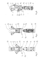
- a device carrier 1 which serves that certain objects can be attached to it.
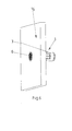
- the conventionally constructed thermally insulated facade has a recess or a bore. The device carrier 1 is inserted into this bore or recess in the assembly target position.
- the device carrier 1 consists of a cylindrical, frontally open at 2 hollow body 3 with integrally formed Spreizarmen 4. This hollow body 3 is inserted into a corresponding hole or perforation of a wall or the like, when the spreading arms are in a position in which they are in the interior the hollow body 3 are displaced, so do not protrude beyond its outer contour.
- the device carrier 1 consists of a hollow body 3 from the front side insertable cylindrical moldings 5. This is adapted in its shape and dimension to the cavity of the hollow body 3 so that it in the installation target position, for example, in FIG. 2 is simulated, fitting in the cavity of the hollow body 3 sits.
- the molded body 5 has on its front side, which closes approximately flush with the mounting position of the mouth of the hollow body 3, a wall with a plurality of perforations 6. To mount an object this can with a corresponding mounting plate having a perforation in front of the end face of the molding 5 are positioned so that a screw penetrating the hole engages in one of the holes 6 and can be screwed into this.
- the screw may for example be a thread-cutting or thread-forming screw, so that a secure fit in the corresponding hole 6 is reached.
- the spreading arms 4 of the hollow body 3 are in a pre-assembly, which is not shown in the drawing, displaced into the cavity of the hollow body 3, so that they do not protrude beyond the missionsvuchtline of the hollow body 3, but protrude into the interior of the hollow body 3.
- the shaped body 5 is completely inserted into the hollow space of the hollow body 3, the spreading body 4 is pivoted radially outward by the shaped body 5, into a position as indicated in the drawing figures. In part, the spread is shown exaggerated in the drawing figures. The actual degree of expansion is slightly lower than, for example, in the FIGS. 4 and 5 is shown.
- Each Sp lantern 4 is formed as over a portion of the length of the hollow body 3 extending, a window-like recess 7 of the hollow body 3 by cross hooks.
- the hook shank 8 is pivotally movable on the end face of the hollow body 3 facing edge of the recess 7, for example via a film hinge formed.
- the tip 9 of the hook protrudes transversely from the shaft 8 and is directed relative to the hollow body 3 to the outside.
- each two spreading arms 4 parallel to the central axis of the hollow body 3 arranged one behind the other and in each case two on opposite sides of the hollow body 3.
- In the embodiment according to FIGS. 3 to 5 are two spreader arms 4 mündungsnah diametrically opposite and arranged two more Sp Schwarzarme offset by 90 ° near the bottom part of the hollow body 3 is arranged.
- a triangular stiffening wall 10 is formed, which is formed with a long edge on the hook shank 8 with a short edge at the top 9.
- the free edge of the stiffening wall 10 forms a cutting edge, which penetrates during spreading of the spreader arms in the surrounding material and ensures a secure fit.
- the tip 9 of the hook the surface element is formed with a cutting edge, wherein its surface extends approximately transversely to the central longitudinal axis of the hollow body 3. As a result, a secure fit of the device carrier 1 is achieved in the perforation.
- the shaped body 5 is fixed in the assembly target position in the hollow body 3 by means of detents 11, wherein these detents 11 engage in recesses 12 of the hollow body 3.
- the fixation of the shaped body 5 in the hollow body 3 can be achieved. It should be ensured in any case that the parts are mutually held non-rotatable and axially immovable when the mounting target position is set.
- the hollow body 3 and also the shaped body 5 each have a conical or wedge-shaped taper 13 or 14 at its end facing away from the front end.
- the hollow body 3 at its front in the insertion direction or in its rear end region in the insertion direction have a circumferential sealing edge or sealing lip of elastomeric material.
- the hollow body 3 and also the molded body 5 at its mouth end on a conically widening collar 15, the latter measures serve to achieve a tight fit in the corresponding hole or recess and also a visually appealing image and a stop to reach in the installed position.
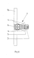
- FIG. 6 is clarified that the complete equipment carrier 1 is installed in a single-layer hollow wall-forming plate 16.
- FIG. 7 It is shown that the spreading arms are spread out in the assembly target position by the shaped body 5, so that they engage with their peripheral edge partly in the region of the bearing hole in the material of the plate 16, partly lie behind this spreads.
- the hollow body 3 at its front end, which is open to receive the shaped body 5, have a flange edge or the like, which is supported on the front side of the corresponding wall 16.
- FIG. 7 the installation target position is shown, wherein a plurality of spreading arms 4 in the longitudinal direction of the Hollow body 3 are provided.
- the spreader arms 4 closest to the mouth are provided with barb-like projections formed on a cutting edge of the spreader arms 4 in order to achieve a good connection with the material of the plate 16 in the area of the bearing hole.
- the spreading arms 4 a serving for locking edge 17 on the edge of the triangular stiffening wall 10, which in turn is used for secure fit of the device carrier 1 in the perforation of the wall 16.
- an alternative wall 17 is shown consisting of two layers. These two layers can be, for example, two gypsum plasterboard. But they can also consist of a combination of a plasterboard with an insulating board or other material combinations.
- FIG. 11 a three-layer plate 18 is shown, which has a perforation for receiving the device carrier 1.
- the device carrier 1, that is, the hollow body 3 and the molded body 5, are preferably made of suitable plastics.
- the inventive design of the device carrier 1 ensures that a largely thermal bridge-free installation of a device carrier, for example in an insulating layer is possible, with a wind-tightness is achieved in this area.
- the corresponding mounting hole or recess usually engages the entire heat-insulating layer to the foundation masonry. It is achieved by the corresponding sealing edges or sealing lips and by the conical collar in this regard, a largely windproof arrangement.
- a tolerance compensation for aligning the device to be fastened to the equipment device is possible because the plurality of perforations 6 allows exact alignment in the vertical or horizontal direction, when several such equipment carriers are arranged side by side or one above the other, not exactly vertical or horizontal to each other in the Hole of the wall are introduced.
- a facade visible damage to the facade are avoided.
- the invention provides a simple design and extremely functional equipment carrier, which is excellently suitable for installation in thermally insulated facades.
Landscapes
- Engineering & Computer Science (AREA)
- Physics & Mathematics (AREA)
- Architecture (AREA)
- Acoustics & Sound (AREA)
- Electromagnetism (AREA)
- Civil Engineering (AREA)
- Structural Engineering (AREA)
- General Engineering & Computer Science (AREA)
- Mechanical Engineering (AREA)
- Finishing Walls (AREA)
- Apparatus Associated With Microorganisms And Enzymes (AREA)
Applications Claiming Priority (2)
| Application Number | Priority Date | Filing Date | Title |
|---|---|---|---|
| DE200910056644 DE102009056644A1 (de) | 2009-12-02 | 2009-12-02 | Geräteträger |
| DE201010046074 DE102010046074A1 (de) | 2010-09-20 | 2010-09-20 | Geräteträger |
Publications (3)
| Publication Number | Publication Date |
|---|---|
| EP2333355A2 true EP2333355A2 (fr) | 2011-06-15 |
| EP2333355A3 EP2333355A3 (fr) | 2014-01-15 |
| EP2333355B1 EP2333355B1 (fr) | 2015-01-14 |
Family
ID=43571545
Family Applications (1)
| Application Number | Title | Priority Date | Filing Date |
|---|---|---|---|
| EP20100401182 Active EP2333355B1 (fr) | 2009-12-02 | 2010-11-05 | Support d'appareillages |
Country Status (2)
| Country | Link |
|---|---|
| EP (1) | EP2333355B1 (fr) |
| DE (1) | DE202010015560U1 (fr) |
Family Cites Families (3)
| Publication number | Priority date | Publication date | Assignee | Title |
|---|---|---|---|---|
| CH688158A5 (de) * | 1994-11-01 | 1997-05-30 | Agro Ag | Vorrichtung zur Befestigung von Apparaten und Gegenstaenden auf einer aussenisolierten Gebaeudefassade und dgl. |
| DE10228255C1 (de) * | 2002-06-25 | 2003-10-16 | Heinz Brunner | Fassadendose |
| DE102006049952B4 (de) * | 2006-10-19 | 2011-02-10 | Zimmer, Günther | Dübel für Deckplattenhintergriff und Deckplatteneinspreizung |
-
2010
- 2010-11-05 DE DE202010015560U patent/DE202010015560U1/de not_active Expired - Lifetime
- 2010-11-05 EP EP20100401182 patent/EP2333355B1/fr active Active
Also Published As
| Publication number | Publication date |
|---|---|
| DE202010015560U1 (de) | 2011-02-10 |
| EP2333355B1 (fr) | 2015-01-14 |
| EP2333355A3 (fr) | 2014-01-15 |
Similar Documents
| Publication | Publication Date | Title |
|---|---|---|
| DE102009006769A1 (de) | Dämmstoffhalter | |
| EP2275613B1 (fr) | Coffrage constitué d'éléments de profil | |
| DE102004064114B4 (de) | Befestigungselement für Dämmstoffplatten | |
| DE2243102A1 (de) | Tragstuetze fuer aufgestaenderte fussboeden | |
| DE102013223292B4 (de) | Beabstandungsvorrichtung | |
| WO2008092664A2 (fr) | Élément de construction | |
| DE102013106975A1 (de) | Abstandshalter | |
| AT510315B1 (de) | Anordnung zur, insbesondere distanzierten, befestigung zumindest einer dämmstoffplatte an einem gebäude | |
| EP2333355B1 (fr) | Support d'appareillages | |
| AT413993B (de) | Isolierte befestigungsvorrichtung für dämmfassaden | |
| WO2009071168A1 (fr) | Dispositif de maintien de matériau isolant et procédé de fixation d'une plaque de matériau isolant | |
| AT9778U1 (de) | Befestigungsvorrichtung | |
| EP3862580A1 (fr) | Dispositif de fixation comprenant une vis et un corps isolant thermique fixé à celle-ci d'une manière rotative et bloquée axialement | |
| DE2229657B2 (de) | Montageplatte fuer moebelscharniere | |
| DE19948468C2 (de) | Aufsatz-Rollladenkasten | |
| DE102005045455B4 (de) | Befestigungseinrichtung für eine Möbelabstützung | |
| EP2330704B1 (fr) | Dispositif de fixation d'une boite d'installation pour installations électriques | |
| DE29508686U1 (de) | Bausatz zum Erstellen von Umkleidekabinen, Trennwänden u.dgl. | |
| DE102009056644A1 (de) | Geräteträger | |
| DE10229115A1 (de) | Zweischaliges Mauerwerk und Verbindungselement dafür | |
| DE10253417B4 (de) | Verbindungssystem für Wandelemente einer Trennwand | |
| DE102010027912A1 (de) | Befestigungselement | |
| DE102010046074A1 (de) | Geräteträger | |
| DE3218457C2 (de) | Dübelbefestigung für Treppenstufen | |
| DE102020101750A1 (de) | Eindrehanker, Anordnung umfassend ein Rahmenprofil und den Eindrehanker und Montageverfahren |
Legal Events
| Date | Code | Title | Description |
|---|---|---|---|
| PUAI | Public reference made under article 153(3) epc to a published international application that has entered the european phase |
Free format text: ORIGINAL CODE: 0009012 |
|
| AK | Designated contracting states |
Kind code of ref document: A2 Designated state(s): AL AT BE BG CH CY CZ DE DK EE ES FI FR GB GR HR HU IE IS IT LI LT LU LV MC MK MT NL NO PL PT RO RS SE SI SK SM TR |
|
| AX | Request for extension of the european patent |
Extension state: BA ME |
|
| PUAL | Search report despatched |
Free format text: ORIGINAL CODE: 0009013 |
|
| AK | Designated contracting states |
Kind code of ref document: A3 Designated state(s): AL AT BE BG CH CY CZ DE DK EE ES FI FR GB GR HR HU IE IS IT LI LT LU LV MC MK MT NL NO PL PT RO RS SE SI SK SM TR |
|
| AX | Request for extension of the european patent |
Extension state: BA ME |
|
| RIC1 | Information provided on ipc code assigned before grant |
Ipc: E04B 1/74 20060101ALI20131206BHEP Ipc: H02G 3/12 20060101ALI20131206BHEP Ipc: H02B 1/40 20060101ALI20131206BHEP Ipc: F16B 13/00 20060101AFI20131206BHEP Ipc: E04B 1/76 20060101ALI20131206BHEP |
|
| 17P | Request for examination filed |
Effective date: 20140704 |
|
| RBV | Designated contracting states (corrected) |
Designated state(s): AL AT BE BG CH CY CZ DE DK EE ES FI FR GB GR HR HU IE IS IT LI LT LU LV MC MK MT NL NO PL PT RO RS SE SI SK SM TR |
|
| GRAP | Despatch of communication of intention to grant a patent |
Free format text: ORIGINAL CODE: EPIDOSNIGR1 |
|
| INTG | Intention to grant announced |
Effective date: 20141029 |
|
| GRAS | Grant fee paid |
Free format text: ORIGINAL CODE: EPIDOSNIGR3 |
|
| GRAA | (expected) grant |
Free format text: ORIGINAL CODE: 0009210 |
|
| AK | Designated contracting states |
Kind code of ref document: B1 Designated state(s): AL AT BE BG CH CY CZ DE DK EE ES FI FR GB GR HR HU IE IS IT LI LT LU LV MC MK MT NL NO PL PT RO RS SE SI SK SM TR |
|
| REG | Reference to a national code |
Ref country code: GB Ref legal event code: FG4D Free format text: NOT ENGLISH |
|
| REG | Reference to a national code |
Ref country code: CH Ref legal event code: EP Ref country code: CH Ref legal event code: NV Representative=s name: TROESCH SCHEIDEGGER WERNER AG, CH |
|
| REG | Reference to a national code |
Ref country code: IE Ref legal event code: FG4D Free format text: LANGUAGE OF EP DOCUMENT: GERMAN |
|
| REG | Reference to a national code |
Ref country code: AT Ref legal event code: REF Ref document number: 707220 Country of ref document: AT Kind code of ref document: T Effective date: 20150215 |
|
| REG | Reference to a national code |
Ref country code: DE Ref legal event code: R096 Ref document number: 502010008725 Country of ref document: DE Effective date: 20150305 |
|
| REG | Reference to a national code |
Ref country code: NL Ref legal event code: VDEP Effective date: 20150114 |
|
| REG | Reference to a national code |
Ref country code: LT Ref legal event code: MG4D |
|
| PG25 | Lapsed in a contracting state [announced via postgrant information from national office to epo] |
Ref country code: FI Free format text: LAPSE BECAUSE OF FAILURE TO SUBMIT A TRANSLATION OF THE DESCRIPTION OR TO PAY THE FEE WITHIN THE PRESCRIBED TIME-LIMIT Effective date: 20150114 Ref country code: HR Free format text: LAPSE BECAUSE OF FAILURE TO SUBMIT A TRANSLATION OF THE DESCRIPTION OR TO PAY THE FEE WITHIN THE PRESCRIBED TIME-LIMIT Effective date: 20150114 Ref country code: SE Free format text: LAPSE BECAUSE OF FAILURE TO SUBMIT A TRANSLATION OF THE DESCRIPTION OR TO PAY THE FEE WITHIN THE PRESCRIBED TIME-LIMIT Effective date: 20150114 Ref country code: LT Free format text: LAPSE BECAUSE OF FAILURE TO SUBMIT A TRANSLATION OF THE DESCRIPTION OR TO PAY THE FEE WITHIN THE PRESCRIBED TIME-LIMIT Effective date: 20150114 Ref country code: NO Free format text: LAPSE BECAUSE OF FAILURE TO SUBMIT A TRANSLATION OF THE DESCRIPTION OR TO PAY THE FEE WITHIN THE PRESCRIBED TIME-LIMIT Effective date: 20150414 Ref country code: ES Free format text: LAPSE BECAUSE OF FAILURE TO SUBMIT A TRANSLATION OF THE DESCRIPTION OR TO PAY THE FEE WITHIN THE PRESCRIBED TIME-LIMIT Effective date: 20150114 Ref country code: BG Free format text: LAPSE BECAUSE OF FAILURE TO SUBMIT A TRANSLATION OF THE DESCRIPTION OR TO PAY THE FEE WITHIN THE PRESCRIBED TIME-LIMIT Effective date: 20150414 |
|
| PG25 | Lapsed in a contracting state [announced via postgrant information from national office to epo] |
Ref country code: PL Free format text: LAPSE BECAUSE OF FAILURE TO SUBMIT A TRANSLATION OF THE DESCRIPTION OR TO PAY THE FEE WITHIN THE PRESCRIBED TIME-LIMIT Effective date: 20150114 Ref country code: GR Free format text: LAPSE BECAUSE OF FAILURE TO SUBMIT A TRANSLATION OF THE DESCRIPTION OR TO PAY THE FEE WITHIN THE PRESCRIBED TIME-LIMIT Effective date: 20150415 Ref country code: RS Free format text: LAPSE BECAUSE OF FAILURE TO SUBMIT A TRANSLATION OF THE DESCRIPTION OR TO PAY THE FEE WITHIN THE PRESCRIBED TIME-LIMIT Effective date: 20150114 Ref country code: LV Free format text: LAPSE BECAUSE OF FAILURE TO SUBMIT A TRANSLATION OF THE DESCRIPTION OR TO PAY THE FEE WITHIN THE PRESCRIBED TIME-LIMIT Effective date: 20150114 Ref country code: NL Free format text: LAPSE BECAUSE OF FAILURE TO SUBMIT A TRANSLATION OF THE DESCRIPTION OR TO PAY THE FEE WITHIN THE PRESCRIBED TIME-LIMIT Effective date: 20150114 Ref country code: IS Free format text: LAPSE BECAUSE OF FAILURE TO SUBMIT A TRANSLATION OF THE DESCRIPTION OR TO PAY THE FEE WITHIN THE PRESCRIBED TIME-LIMIT Effective date: 20150514 |
|
| REG | Reference to a national code |
Ref country code: DE Ref legal event code: R097 Ref document number: 502010008725 Country of ref document: DE |
|
| PG25 | Lapsed in a contracting state [announced via postgrant information from national office to epo] |
Ref country code: CZ Free format text: LAPSE BECAUSE OF FAILURE TO SUBMIT A TRANSLATION OF THE DESCRIPTION OR TO PAY THE FEE WITHIN THE PRESCRIBED TIME-LIMIT Effective date: 20150114 Ref country code: SK Free format text: LAPSE BECAUSE OF FAILURE TO SUBMIT A TRANSLATION OF THE DESCRIPTION OR TO PAY THE FEE WITHIN THE PRESCRIBED TIME-LIMIT Effective date: 20150114 Ref country code: RO Free format text: LAPSE BECAUSE OF FAILURE TO SUBMIT A TRANSLATION OF THE DESCRIPTION OR TO PAY THE FEE WITHIN THE PRESCRIBED TIME-LIMIT Effective date: 20150114 Ref country code: DK Free format text: LAPSE BECAUSE OF FAILURE TO SUBMIT A TRANSLATION OF THE DESCRIPTION OR TO PAY THE FEE WITHIN THE PRESCRIBED TIME-LIMIT Effective date: 20150114 Ref country code: EE Free format text: LAPSE BECAUSE OF FAILURE TO SUBMIT A TRANSLATION OF THE DESCRIPTION OR TO PAY THE FEE WITHIN THE PRESCRIBED TIME-LIMIT Effective date: 20150114 |
|
| PLBE | No opposition filed within time limit |
Free format text: ORIGINAL CODE: 0009261 |
|
| STAA | Information on the status of an ep patent application or granted ep patent |
Free format text: STATUS: NO OPPOSITION FILED WITHIN TIME LIMIT |
|
| 26N | No opposition filed |
Effective date: 20151015 |
|
| PG25 | Lapsed in a contracting state [announced via postgrant information from national office to epo] |
Ref country code: IT Free format text: LAPSE BECAUSE OF FAILURE TO SUBMIT A TRANSLATION OF THE DESCRIPTION OR TO PAY THE FEE WITHIN THE PRESCRIBED TIME-LIMIT Effective date: 20150114 |
|
| PG25 | Lapsed in a contracting state [announced via postgrant information from national office to epo] |
Ref country code: SI Free format text: LAPSE BECAUSE OF FAILURE TO SUBMIT A TRANSLATION OF THE DESCRIPTION OR TO PAY THE FEE WITHIN THE PRESCRIBED TIME-LIMIT Effective date: 20150114 |
|
| PG25 | Lapsed in a contracting state [announced via postgrant information from national office to epo] |
Ref country code: LU Free format text: LAPSE BECAUSE OF FAILURE TO SUBMIT A TRANSLATION OF THE DESCRIPTION OR TO PAY THE FEE WITHIN THE PRESCRIBED TIME-LIMIT Effective date: 20151105 Ref country code: MC Free format text: LAPSE BECAUSE OF FAILURE TO SUBMIT A TRANSLATION OF THE DESCRIPTION OR TO PAY THE FEE WITHIN THE PRESCRIBED TIME-LIMIT Effective date: 20150114 |
|
| GBPC | Gb: european patent ceased through non-payment of renewal fee |
Effective date: 20151105 |
|
| REG | Reference to a national code |
Ref country code: IE Ref legal event code: MM4A |
|
| REG | Reference to a national code |
Ref country code: FR Ref legal event code: ST Effective date: 20160729 |
|
| PG25 | Lapsed in a contracting state [announced via postgrant information from national office to epo] |
Ref country code: IE Free format text: LAPSE BECAUSE OF NON-PAYMENT OF DUE FEES Effective date: 20151105 Ref country code: GB Free format text: LAPSE BECAUSE OF NON-PAYMENT OF DUE FEES Effective date: 20151105 |
|
| PG25 | Lapsed in a contracting state [announced via postgrant information from national office to epo] |
Ref country code: FR Free format text: LAPSE BECAUSE OF NON-PAYMENT OF DUE FEES Effective date: 20151130 |
|
| PG25 | Lapsed in a contracting state [announced via postgrant information from national office to epo] |
Ref country code: SM Free format text: LAPSE BECAUSE OF FAILURE TO SUBMIT A TRANSLATION OF THE DESCRIPTION OR TO PAY THE FEE WITHIN THE PRESCRIBED TIME-LIMIT Effective date: 20150114 Ref country code: HU Free format text: LAPSE BECAUSE OF FAILURE TO SUBMIT A TRANSLATION OF THE DESCRIPTION OR TO PAY THE FEE WITHIN THE PRESCRIBED TIME-LIMIT; INVALID AB INITIO Effective date: 20101105 |
|
| PG25 | Lapsed in a contracting state [announced via postgrant information from national office to epo] |
Ref country code: CY Free format text: LAPSE BECAUSE OF FAILURE TO SUBMIT A TRANSLATION OF THE DESCRIPTION OR TO PAY THE FEE WITHIN THE PRESCRIBED TIME-LIMIT Effective date: 20150114 |
|
| PG25 | Lapsed in a contracting state [announced via postgrant information from national office to epo] |
Ref country code: BE Free format text: LAPSE BECAUSE OF NON-PAYMENT OF DUE FEES Effective date: 20151130 |
|
| PG25 | Lapsed in a contracting state [announced via postgrant information from national office to epo] |
Ref country code: MT Free format text: LAPSE BECAUSE OF FAILURE TO SUBMIT A TRANSLATION OF THE DESCRIPTION OR TO PAY THE FEE WITHIN THE PRESCRIBED TIME-LIMIT Effective date: 20150114 Ref country code: TR Free format text: LAPSE BECAUSE OF FAILURE TO SUBMIT A TRANSLATION OF THE DESCRIPTION OR TO PAY THE FEE WITHIN THE PRESCRIBED TIME-LIMIT Effective date: 20150114 |
|
| PG25 | Lapsed in a contracting state [announced via postgrant information from national office to epo] |
Ref country code: MK Free format text: LAPSE BECAUSE OF FAILURE TO SUBMIT A TRANSLATION OF THE DESCRIPTION OR TO PAY THE FEE WITHIN THE PRESCRIBED TIME-LIMIT Effective date: 20150114 Ref country code: PT Free format text: LAPSE BECAUSE OF FAILURE TO SUBMIT A TRANSLATION OF THE DESCRIPTION OR TO PAY THE FEE WITHIN THE PRESCRIBED TIME-LIMIT Effective date: 20150114 |
|
| PG25 | Lapsed in a contracting state [announced via postgrant information from national office to epo] |
Ref country code: AL Free format text: LAPSE BECAUSE OF FAILURE TO SUBMIT A TRANSLATION OF THE DESCRIPTION OR TO PAY THE FEE WITHIN THE PRESCRIBED TIME-LIMIT Effective date: 20150114 |
|
| REG | Reference to a national code |
Ref country code: CH Ref legal event code: U11 Free format text: ST27 STATUS EVENT CODE: U-0-0-U10-U11 (AS PROVIDED BY THE NATIONAL OFFICE) Effective date: 20251222 |
|
| PGFP | Annual fee paid to national office [announced via postgrant information from national office to epo] |
Ref country code: AT Payment date: 20251124 Year of fee payment: 16 |
|
| PGFP | Annual fee paid to national office [announced via postgrant information from national office to epo] |
Ref country code: CH Payment date: 20251222 Year of fee payment: 16 |
|
| REG | Reference to a national code |
Ref country code: DE Ref legal event code: R082 Ref document number: 502010008725 Country of ref document: DE Representative=s name: KOECHLING, MARIETTA, M.SC B.ENG., DE |
|
| PGFP | Annual fee paid to national office [announced via postgrant information from national office to epo] |
Ref country code: DE Payment date: 20260131 Year of fee payment: 16 |