EP2333390B1 - Soupape à tiroir hydraulique avec dispositif de positionnement - Google Patents
Soupape à tiroir hydraulique avec dispositif de positionnement Download PDFInfo
- Publication number
- EP2333390B1 EP2333390B1 EP09015383A EP09015383A EP2333390B1 EP 2333390 B1 EP2333390 B1 EP 2333390B1 EP 09015383 A EP09015383 A EP 09015383A EP 09015383 A EP09015383 A EP 09015383A EP 2333390 B1 EP2333390 B1 EP 2333390B1
- Authority
- EP
- European Patent Office
- Prior art keywords
- lever
- hand lever
- housing
- friction brake
- shaft
- Prior art date
- Legal status (The legal status is an assumption and is not a legal conclusion. Google has not performed a legal analysis and makes no representation as to the accuracy of the status listed.)
- Active
Links
Images

Classifications
-
- F—MECHANICAL ENGINEERING; LIGHTING; HEATING; WEAPONS; BLASTING
- F16—ENGINEERING ELEMENTS AND UNITS; GENERAL MEASURES FOR PRODUCING AND MAINTAINING EFFECTIVE FUNCTIONING OF MACHINES OR INSTALLATIONS; THERMAL INSULATION IN GENERAL
- F16K—VALVES; TAPS; COCKS; ACTUATING-FLOATS; DEVICES FOR VENTING OR AERATING
- F16K35/00—Means to prevent accidental or unauthorised actuation
- F16K35/04—Means to prevent accidental or unauthorised actuation yieldingly resisting the actuation
Definitions
- the invention relates to a hydraulic slide valve according to the preamble of patent claim 1.
- the positioning device coupled to the spool piston, linearly adjustable sleeve with an external thread, as well as radially inwardly biased detent balls for cooperation with the external thread of the sleeve.
- the sleeve with its external thread or the grooves and the resiliently biased detent balls form a friction brake whose braking torque inhibits the spool and also the hand lever due to the coupling of the hand lever with the slider.
- the external thread of the sleeve can have an additional recess which is blended with the threads.
- the locking balls are arranged in an external thread with thread pitch in a common radial plane.
- the detent balls are positioned offset from one another obliquely relative to the radial plane of the grooves.
- the positioning device with the friction brake is arranged separately from the hand lever in a separate housing on the valve housing of the hydraulic slide valve.
- the positioning device is housed in a separate sealed housing at the opposite end of the hand lever valve housing.
- Radially inwardly biased detent balls work with detent recesses in the outer circumference of a sleeve connected to the spool, the sleeve whose linear displacement moves along.
- the hand lever is mounted in a lever housing on the pivot axis and engages with a coupling on the extended end of the spool.
- Such positioning devices are particularly suitable for devices in which a manually selected adjustment position of the spool is to be kept unchanged until another adjustment position, e.g. by means of the hand lever, is set. This is the case, for example, with rock drilling machines, in which a worker must be sure, even under poor visibility, that the selected adjustment position and thus the working speed of the device does not change. Furthermore, it is often expedient in such machines, if the adjustable at least by means of the hand lever spool is positionable in at least one selected, clearly perceptible to the hand lever adjustment position, and this complies with until a further adjustment, e.g. on the hand lever, is made.
- a hand lever friction brake is installed in the lever housing having a concentric with the pivot axis brake surface, stationary brake pad the hand lever directly with a Applied to braking torque, which is generated by a mounted on the outside of the hand lever Wellfederelement and its axial bias.
- On the hand lever further at least one locking element is formed, which cooperates with a formed in the braking surface of the brake pad notch to additionally lock a predetermined adjustment position of the hand lever.
- a known held by frictional locking device for a train or a rod for transmitting an actuating movement are provided between the hand lever and a stationary support two spaced, parallel pivot axes.
- the one pivot axis supports the hand lever pivotally on two tabs, which clamp a lever carrier between them, which is pivotable relative to the tabs with the hand lever.
- the two tabs are pivotable about the other pivot axis on the stationary support and thereby inhibited against pivotal movement by frictional engagement.
- the frictional engagement is generated by a disc spring arrangement on the one pivot axis.
- the bias of the disc springs can be overcome temporarily by a ball mechanism between the lever carrier and one of the tabs to cancel the frictional engagement of the tabs on the stationary support, so that after an initial movement of the hand lever for actuating the ball mechanism of the hand lever together with the tabs unbraked to the stationary support is pivotable. With the tabs of the train or the rod for transmitting the adjusting movement is coupled.
- the invention has for its object to improve a hydraulic slide valve of the type mentioned in that any adjustment of an at least manually adjustable spool are structurally simple and inexpensive way preserved.
- the hand lever In the hydraulic slide valve, in departure from the known principle to inhibit the spool directly, the hand lever is acted upon by the hand lever friction brake with a uniform braking torque, which must overcome the user to bring the spool to a new adjustment position.
- the coupling between the hand lever and the spool is designed so that the spool either always follows the hand lever movement, eg by spring action or hydraulic Actuation, or is coupled to the hand lever in both adjustment directions, so that the braked, not actuated hand lever holds the spool.
- the hand lever friction brake is structurally simple and space-saving housable in the area in which the hand lever is mounted on the valve body. Thus, additional space for other equipment components remains free at the valve housing.
- the braking torque for the hand lever can be adjusted as needed, and either act continuously, or with noticeable detents, or can in one or the other direction of movement of the hand lever or increase.
- the hand lever friction brake is functionally reliable, has no significant wear, and acts largely independent of temperature and vibration influences.
- the hand lever is inhibited so that it is not moved automatically by shaking or by the spool back forces, but is adjustable by hand with only reasonable effort. Since it is expedient for hydraulic slide valves, at least to provide a selected adjustment position, for example according to the zero position, the achievement of which should be clearly felt when moving the hand lever, for additional positioning of the spool in the at least one selected adjustment of the hand lever friction brake functionally a ball lock assigned.
- the ball lock is structurally combined with the hand lever friction brake and acts between the hand lever and the lever housing.
- the additional positioning of the ball latch is thus realized without stress appreciable space, and such that the ball latch and the hand lever friction brake work together without mutual interference.
- the hand lever is provided in a valve housing arranged on the lever housing and coupled to the spool.
- the hand lever friction brake has at least one spring element as a brake element.
- a brake element may be provided a plate spring or disc spring package, or other spring elements such as corrugated springs, ring springs, plastic springs, or other springs.
- the braking element is biased in the direction of the pivot axis against a braking surface and generates in cooperation with the braking surface without additional components, both the bias voltage and the braking element.
- the combined with the hand lever friction brake ball latch to the pivot axis is arranged concentrically and radially inside and / or outside of the hand lever friction brake.
- the hand lever is coupled to the spool via at least one rotatably mounted in the lever housing about the pivot axis mounted shaft, wherein the hand lever friction brake and the ball latching are arranged functionally between the lever housing and the shaft.
- a plate spring or a plate spring package as the brake element in which the disc springs are connected in series generates a very high and permanent braking force, which also can be set very precisely and wear-independent remains effective over long periods.
- the resulting from the bias of the braking element counterforce is supported by the shaft on the lever housing.
- the biasing force can be absorbed in other ways, without burdening the shaft.
- an outwardly sealable inner chamber may be provided, in which a spool actuator is arranged on the shaft.
- the hand lever friction brake and the ball latch are located on the outside of the lever housing, i. H. expedient outside of an area in which hydraulic medium penetrates and / or at least a certain pressure prevails.
- the lever housing with the hand lever and the hand lever friction brake plus the ball lock can form a prefabricated unit that fits different valve types or is easily adaptable to such. With the unit can also be made a subsequent conversion of a hydraulic slide valve.
- the brake element is inserted on the shaft in a socket of a lever carrier.
- a socket of a lever carrier This is, for example, a conically recessed seat, so that the brake element in the direction of the pivot axis of the hand lever takes up as little space as possible.
- the shaft against the bias with which the brake element is pressed in the direction of the pivot axis against the braking surface, for example, on the lever housing, supported relative to the lever housing.
- This solution is structurally simple and reliable, because the shaft is braked in its rotational movement and at the same time transmits the bias voltage.
- the brake element could be arranged on the lever housing (for example recessed) and interact with a braking surface on the lever carrier.
- a sleeve supported on the lever housing is mounted on an end of the shaft protruding from the lever housing.
- the sleeve can be removably fixed by means of a snap ring on the shaft, or by a screw or a grub screw, or the like. This facilitates the assembly and Disassembly of the positioning of the hydraulic slide valve.
- a screw connection allows changing the bias voltage.
- the hand lever friction brake could even be housed inside the lever housing.
- a structurally simple embodiment of the ball latch has a lever carrier radially outside the hand lever friction brake at least one spring-loaded detent ball and at least one arranged in the outer side of the lever housing latching recess.
- the ball lock could also be placed inside the lever housing and there between the shaft and the lever housing. The accommodation in the lever carrier and on the outside of the lever housing manufacturing and assembly technology may be cheaper.
- lever carrier and a spool actuator disposed in an inner chamber of the lever housing are each mounted with a grooved pin on the shaft.
- the positioning device which can be mounted as a prefabricatable assembly on various hydraulic spool valve types, is designed so that the hand lever is mounted with a lever carrier on a rotatably mounted in a lever housing shaft.
- the hand lever friction brake is disposed on the shaft and functionally between the lever carrier and the lever housing. In this area, the ball lock is housed.
- the two tasks to generate the braking torque and to support the biasing force for the braking torque are advantageously solved so that the sleeve and the brake element are arranged with respect to the pivot axis on opposite outer sides of the lever housing.
- This also offers advantages in that, if appropriate, the lever housing has a pressure medium-containing and / or pressurizable inner chamber and no pressure medium should reach the hand lever friction brake.
- the hand lever friction brake could be accommodated even inside the lever housing, where then the bias voltage can be supported, for example, if the interior of the lever housing contains no hydraulic pressure medium.
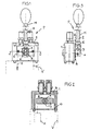
- Fig. 1 Dashed lines illustrates a hydraulic slide valve V with at least one linearly adjustable and definable in each adjustment slide piston K or other linearly adjustable valve element.
- a positioning device P with a lever operation for the respective spool K mounted.
- the spool K is linearly adjusted when a hand lever H is moved about a pivot axis X.
- the hand lever H is mounted on a lever housing 1 which is mounted on the valve housing of the hydraulic slide valve V and rotatably supports a shaft 4 whose axis coincides with the pivot axis X.
- the hand lever H has, for example, a lever rod 2, which is mounted with a nut 6 in a lever carrier 3, which is fixed on a protruding end of the shaft 4 by means of a notched pin 5 on the outside of the lever housing 1.
- a spool actuator 7 is mounted, here for example a two-armed lever for mutual operation, for example, two spool.
- the spool actuator 7 may also be designed differently, for example so that it is coupled in both adjustment directions of the spool with this.
- the spool K always in contact with the spool actuator 7 remains, for example by spring action or hydraulic loading or the like .
- the spool K therefore makes every movement of the spool actuator 7 and remains detained in the respective adjustment when the spool actuator 7 is fixed about the pivot axis X.
- the inner chamber 9 is sealed for example by a seal 10 to the outside.
- the lever carrier 3 is associated with an outer side 16 of the lever housing 1 and is provided here in the area between the lever carrier 3 and the lever housing 1, at least one hand lever friction brake B, which determines the hand lever H in any position of its range of motion, as long as not an operator the braking resistor or intentionally overcomes the acting braking torque.
- the positioning device P especially in Fig. 3 , equipped with a ball lock R, which makes it possible to lock the hand lever H and thus the spool K in at least one selected position in addition to the action of the hand lever friction brake B, such that an operator despite the braking feels on the hand lever H, if this selected position has been set.
- the positioning device P will be described in detail Fig. 4 explained.
- the shaft 4 passing through the lever housing 1 projects with both ends beyond the outer sides 15, 16 of the lever housing 1 facing away from one another, and is in bores of the lever housing 1, for example sealed by O-rings 11 rotatable.
- a sleeve 12 is mounted, which is supported against the outer side 15.
- the sleeve 12 may be detachably fixed by means of a snap ring 13 in a groove 14 on the shaft 4.
- the sleeve 12 transmits an acting in the direction of the pivot axis X bias for a brake element E of the hand lever friction brake B on the outer side 15 of the lever housing. 1
- the brake element E of the hand lever friction brake B is in the embodiment shown a disc spring 19 or a package of series-connected disc springs 19, inserted into a seat 18 in the lever carrier 3.
- the seat 18 is for example a conical recess.
- Each disc spring 19 surrounds the shaft 4.
- the plate spring 19 facing the outer side 16 of the lever housing 1 bears against a braking surface 17, which is formed either directly from the outer side 16 or provided in this.
- lever carrier 3 mounted on the shaft 4 is positioned over the sleeve 12 relative to the outside 16 of the lever housing 1 so that the braking element E is biased and, provided that the braking surface 17 is flat, generates a uniform braking torque about the pivot axis X, that determines the hand lever H in the respective position via the lever carrier 3, and in the sequence via the spool actuator 7 and the associated spool K.
- disc springs 19 instead of one or more disc springs 19, it would also be possible to use corrugated rings, ring springs, or other spring elements, or plastic springs, possibly even with an annular brake body (not shown).
- the sleeve 12 or a technically equivalent stop could be fixed by a screw, for example, such that the bias for the brake element E is adjustable or adjustable to change the braking torque.
- the optionally additionally provided ball lock R is provided in the embodiment shown concentrically to the pivot axis X and radially outside of the hand lever friction brake B.
- a detent ball 20 is arranged axially displaceably, which is pressed by a spring 23 in a provided in the outer side 16 latching recess 21.
- the spring 23 is supported for example by a screw 24 in the lever carrier 3.
- the ball latch R is engaged. If the hand lever H from the in Fig. 4 shown position moves about the pivot axis X, then exits the at least one detent ball 20 from the locking recess 21 and rolls on the flat outer side 16, while the hand lever friction brake B continues to operate with its adjusted braking torque.
- not shown embodiment could be arranged at both ends of the shaft 4 and outside the lever housing 1 hand lever friction brakes B, acting in the direction of the pivot axis X bias cancel or compensate each other. Furthermore, at least the hand lever friction brake B and / or the ball latch R could be accommodated in the inner chamber 9 of the lever housing 1.
- the spool K could additionally be linearly adjusted in other ways than by hand without using the hand lever H, for example by means of magnets, a hydraulic precontrol or the like.
Landscapes
- Engineering & Computer Science (AREA)
- General Engineering & Computer Science (AREA)
- Mechanical Engineering (AREA)
- Mechanically-Actuated Valves (AREA)
- Preventing Unauthorised Actuation Of Valves (AREA)
Claims (9)
- Soupape à tiroir hydraulique (V), comprenant au moins un piston à coulisse (K) déplaçable linéairement dans un corps de soupape, au moins manuellement, au moyen d'un levier à main (H) mobile autour d'un axe de pivotement (X), et couplé au levier (H), et un dispositif de positionnement (P) par force de friction pour fixer le piston à coulisse (K) dans chaque position de déplacement par l'intermédiaire d'un frein à friction, le levier à main (H) étant monté sur un carter de levier (1) disposé sur le corps de soupape, caractérisée en ce que le frein à friction est un frein à friction (B) de levier à main et est disposé entre le levier à main (H) et le carter de levier (1), fixe par un couple de freinage, dans chaque position de déplacement du piston à coulisse (K), le levier à main (H) par rapport au carter de levier (1) contre un déplacement automatique autour de l'axe de pivotement (X), au moins sous l'effet d'une force de rétroaction du piston à coulisse (K), que le frein à friction (B) de levier à main présente, en tant qu'élément de freinage (E), au moins un élément à ressort précontraint en direction de l'axe de pivotement (X) contre une surface de freinage (17), et qu'un encliquetage à bille (R) est associé fonctionnellement, pour le positionnement supplémentaire du piston à coulisse (K) dans au moins une position de déplacement sélectionnée du frein à friction (B) de levier à main, entre le levier à main (H) et le carter de levier (1).
- Soupape à tiroir hydraulique suivant la revendication 1, caractérisée en ce que l'encliquetage à bille (R) est disposé concentriquement à l'axe de pivotement (X) et dans la direction radiale à l'intérieur et/ou à l'extérieur du frein à friction (B) de levier à main.
- Soupape à tiroir hydraulique suivant la revendication 1, caractérisée en ce que le levier à main (H) est couplé au piston à coulisse (K) par l'intermédiaire d'un arbre (4) monté tournant dans le carter de levier (1) autour de l'axe de pivotement (X), et que le frein à friction (B) de levier à main et l'accouplement à bille (R) sont disposés fonctionnellement entre le carter de levier (1) et l'arbre (4).
- Soupape à tiroir hydraulique suivant la revendication 3, caractérisée en ce que le frein à friction (B) de levier à main présente, en tant qu'élément de freinage (E), au moins un ressort à disques (19), de préférence un paquet de ressorts à disques, que la surface de freinage (17) est disposée extérieurement sur le carter de levier (1), et que la force antagoniste, résultante de la précontrainte de l'élément de freinage (E), est supportée par l'arbre (4) sur le carter de levier (1).
- Soupape à tiroir hydraulique suivant la revendication 3, caractérisée en ce que le carter de levier (1) présente un compartiment intérieur (9) rendu étanche vers l'extérieur, dans lequel est disposé sur l'arbre (4) un actionneur (7) de piston à coulisse.
- Soupape à tiroir hydraulique suivant la revendication 3, caractérisée en ce que l'élément de freinage (E) est mis en place sur l'arbre (4) dans un châssis (18), de préférence un siège creusé en cône, d'un support de levier (3).
- Soupape à tiroir hydraulique suivant la revendication 4, caractérisée en ce qu'un manchon (12), s'appuyant sur le carter de levier (1), est monté sur une extrémité de l'arbre (4) dépassant du carter de levier (1), de préférence au moyen d'un circlip (13) ou d'un vissage.
- Soupape à tiroir hydraulique suivant la revendication 1, caractérisée en ce que l'encliquetage à bille (R) présente, dans la direction radiale extérieurement au frein à friction (B) de levier à main, au moins une bille d'encliquetage (20) à ressort dans un support de levier (3) et au moins un creux d'encliquetage, disposé dans le carter extérieur (16) du carter de levier (1).
- Soupape à tiroir hydraulique suivant l'une au moins des revendications précédentes, caractérisée en ce que le support de levier (3) et l'actionneur (7) de piston à coulisse, disposé dans le compartiment intérieur (9) du carter de levier (1), sont montés dans l'arbre (4) par des goupilles élastiques fendues (5, 8).
Priority Applications (2)
| Application Number | Priority Date | Filing Date | Title |
|---|---|---|---|
| EP09015383A EP2333390B1 (fr) | 2009-12-11 | 2009-12-11 | Soupape à tiroir hydraulique avec dispositif de positionnement |
| AT09015383T ATE545815T1 (de) | 2009-12-11 | 2009-12-11 | Hydraulik-schieberventil mit positioniervorrichtung |
Applications Claiming Priority (1)
| Application Number | Priority Date | Filing Date | Title |
|---|---|---|---|
| EP09015383A EP2333390B1 (fr) | 2009-12-11 | 2009-12-11 | Soupape à tiroir hydraulique avec dispositif de positionnement |
Publications (2)
| Publication Number | Publication Date |
|---|---|
| EP2333390A1 EP2333390A1 (fr) | 2011-06-15 |
| EP2333390B1 true EP2333390B1 (fr) | 2012-02-15 |
Family
ID=41666387
Family Applications (1)
| Application Number | Title | Priority Date | Filing Date |
|---|---|---|---|
| EP09015383A Active EP2333390B1 (fr) | 2009-12-11 | 2009-12-11 | Soupape à tiroir hydraulique avec dispositif de positionnement |
Country Status (2)
| Country | Link |
|---|---|
| EP (1) | EP2333390B1 (fr) |
| AT (1) | ATE545815T1 (fr) |
Families Citing this family (1)
| Publication number | Priority date | Publication date | Assignee | Title |
|---|---|---|---|---|
| EP3088782B1 (fr) * | 2015-04-29 | 2019-09-18 | HAWE Hydraulik SE | Vanne de commande hydraulique en construction à coulisse et installation hydraulique mobile dotée d'une vanne de commande correspondante |
Family Cites Families (5)
| Publication number | Priority date | Publication date | Assignee | Title |
|---|---|---|---|---|
| US3602245A (en) | 1970-02-26 | 1971-08-31 | Abex Corp | Universal detent positioner |
| US4543851A (en) | 1982-06-23 | 1985-10-01 | Acf Industries, Incorporated | Torque application assembly for closure valve of a railroad hopper car outlet |
| DE3432736A1 (de) | 1984-05-05 | 1985-11-14 | Losenhausen Maschinenbau AG & Co KG, 4000 Düsseldorf | Durch reibschluss gehaltene stellvorrichtung |
| US4949591A (en) | 1988-04-15 | 1990-08-21 | Capro, Inc. | Lever control |
| DE20212458U1 (de) | 2002-08-13 | 2003-12-24 | Hawe Hydraulik Gmbh & Co. Kg | Festsetzvorrichtung und Hydraulik-Schieberventil |
-
2009
- 2009-12-11 EP EP09015383A patent/EP2333390B1/fr active Active
- 2009-12-11 AT AT09015383T patent/ATE545815T1/de active
Also Published As
| Publication number | Publication date |
|---|---|
| EP2333390A1 (fr) | 2011-06-15 |
| ATE545815T1 (de) | 2012-03-15 |
Similar Documents
| Publication | Publication Date | Title |
|---|---|---|
| DE69509125T2 (de) | Mutteranordnung mit spielbeseitigung | |
| EP0452702B1 (fr) | Dispositif de fixation pour une unité de mouvement linéaire | |
| EP3084277B1 (fr) | Dispositif de vanne hydraulique | |
| DE2608502B2 (de) | Lösevorrichtung für die Unterbrechung und automatische Rückführung der Betriebsfunktion eines Federspeicherbremszyiinders | |
| DE102015202916A1 (de) | Kupplungsvorrichtung mit Hebelbetätigung | |
| DE102017008196A1 (de) | Trommelbremse mit einem elektromechanisch-hydraulischen Bremsaktuator | |
| DE202008016454U1 (de) | Werkzeug zum Polieren und Feinschleifen von optisch wirksamen Flächen in der Feinoptik | |
| DE19907483C2 (de) | Beidseitig wirkende Verstellvorrichtung | |
| EP2333390B1 (fr) | Soupape à tiroir hydraulique avec dispositif de positionnement | |
| EP0208827A1 (fr) | Pince | |
| DE4125706C1 (fr) | ||
| DE112013007620T5 (de) | Ventilbetätigungsanordnung mit Reibmittel und Vorspannelement | |
| WO2002033286A1 (fr) | Dispositif permettant de declencher un ressort a gaz | |
| DE2707124C2 (de) | Manuelle Nachstellvorrichtung für den Bremsbelagverschleiß einer mechanisch betätigbaren Schwimmsattel-Scheibenbremse | |
| DE19637296A1 (de) | Kolben/Zylinder-Anordnung | |
| DE1751931A1 (de) | Doppelwirkender,druckmittelgesteuerter Zylinder | |
| EP1618312B1 (fr) | Entrainement a action bilaterale | |
| DE102016015728A1 (de) | Parksperren-Aktuatoreinheit | |
| EP3298312B1 (fr) | Dispositif d'actionnement de levier à galet et ensemble de soupape à levier à galet équipé de celui-ci | |
| DE19750614C2 (de) | Vorrichtung zum Verändern des Verdrängungsvolumens einer hydrostatischen Maschine | |
| EP4104966B1 (fr) | Dispositif de serrage | |
| WO2020156614A2 (fr) | Arrêt de porte | |
| DE2905799C2 (de) | Pneumatischer Stellungsregler mit Spiralmeßfeder | |
| CH663992A5 (de) | Steuerkartusche. | |
| DE2404320C2 (fr) |
Legal Events
| Date | Code | Title | Description |
|---|---|---|---|
| PUAI | Public reference made under article 153(3) epc to a published international application that has entered the european phase |
Free format text: ORIGINAL CODE: 0009012 |
|
| 17P | Request for examination filed |
Effective date: 20100914 |
|
| AK | Designated contracting states |
Kind code of ref document: A1 Designated state(s): AT BE BG CH CY CZ DE DK EE ES FI FR GB GR HR HU IE IS IT LI LT LU LV MC MK MT NL NO PL PT RO SE SI SK SM TR |
|
| AX | Request for extension of the european patent |
Extension state: AL BA RS |
|
| GRAP | Despatch of communication of intention to grant a patent |
Free format text: ORIGINAL CODE: EPIDOSNIGR1 |
|
| RIC1 | Information provided on ipc code assigned before grant |
Ipc: F16K 35/04 20060101AFI20110707BHEP Ipc: G05G 5/16 20060101ALI20110707BHEP Ipc: G05G 5/22 20060101ALI20110707BHEP |
|
| RTI1 | Title (correction) |
Free format text: HYDRAULIC GATE VALVE WITH POSITIONING DEVICE |
|
| GRAS | Grant fee paid |
Free format text: ORIGINAL CODE: EPIDOSNIGR3 |
|
| GRAA | (expected) grant |
Free format text: ORIGINAL CODE: 0009210 |
|
| AK | Designated contracting states |
Kind code of ref document: B1 Designated state(s): AT BE BG CH CY CZ DE DK EE ES FI FR GB GR HR HU IE IS IT LI LT LU LV MC MK MT NL NO PL PT RO SE SI SK SM TR |
|
| REG | Reference to a national code |
Ref country code: GB Ref legal event code: FG4D Free format text: NOT ENGLISH Ref country code: CH Ref legal event code: EP |
|
| REG | Reference to a national code |
Ref country code: IE Ref legal event code: FG4D Free format text: LANGUAGE OF EP DOCUMENT: GERMAN |
|
| REG | Reference to a national code |
Ref country code: AT Ref legal event code: REF Ref document number: 545815 Country of ref document: AT Kind code of ref document: T Effective date: 20120315 |
|
| REG | Reference to a national code |
Ref country code: DE Ref legal event code: R096 Ref document number: 502009002776 Country of ref document: DE Effective date: 20120412 |
|
| REG | Reference to a national code |
Ref country code: NL Ref legal event code: VDEP Effective date: 20120215 |
|
| LTIE | Lt: invalidation of european patent or patent extension |
Effective date: 20120215 |
|
| PG25 | Lapsed in a contracting state [announced via postgrant information from national office to epo] |
Ref country code: HR Free format text: LAPSE BECAUSE OF FAILURE TO SUBMIT A TRANSLATION OF THE DESCRIPTION OR TO PAY THE FEE WITHIN THE PRESCRIBED TIME-LIMIT Effective date: 20120215 Ref country code: NO Free format text: LAPSE BECAUSE OF FAILURE TO SUBMIT A TRANSLATION OF THE DESCRIPTION OR TO PAY THE FEE WITHIN THE PRESCRIBED TIME-LIMIT Effective date: 20120515 Ref country code: IS Free format text: LAPSE BECAUSE OF FAILURE TO SUBMIT A TRANSLATION OF THE DESCRIPTION OR TO PAY THE FEE WITHIN THE PRESCRIBED TIME-LIMIT Effective date: 20120615 Ref country code: NL Free format text: LAPSE BECAUSE OF FAILURE TO SUBMIT A TRANSLATION OF THE DESCRIPTION OR TO PAY THE FEE WITHIN THE PRESCRIBED TIME-LIMIT Effective date: 20120215 Ref country code: LT Free format text: LAPSE BECAUSE OF FAILURE TO SUBMIT A TRANSLATION OF THE DESCRIPTION OR TO PAY THE FEE WITHIN THE PRESCRIBED TIME-LIMIT Effective date: 20120215 |
|
| PG25 | Lapsed in a contracting state [announced via postgrant information from national office to epo] |
Ref country code: PL Free format text: LAPSE BECAUSE OF FAILURE TO SUBMIT A TRANSLATION OF THE DESCRIPTION OR TO PAY THE FEE WITHIN THE PRESCRIBED TIME-LIMIT Effective date: 20120215 Ref country code: FI Free format text: LAPSE BECAUSE OF FAILURE TO SUBMIT A TRANSLATION OF THE DESCRIPTION OR TO PAY THE FEE WITHIN THE PRESCRIBED TIME-LIMIT Effective date: 20120215 Ref country code: LV Free format text: LAPSE BECAUSE OF FAILURE TO SUBMIT A TRANSLATION OF THE DESCRIPTION OR TO PAY THE FEE WITHIN THE PRESCRIBED TIME-LIMIT Effective date: 20120215 Ref country code: GR Free format text: LAPSE BECAUSE OF FAILURE TO SUBMIT A TRANSLATION OF THE DESCRIPTION OR TO PAY THE FEE WITHIN THE PRESCRIBED TIME-LIMIT Effective date: 20120516 Ref country code: PT Free format text: LAPSE BECAUSE OF FAILURE TO SUBMIT A TRANSLATION OF THE DESCRIPTION OR TO PAY THE FEE WITHIN THE PRESCRIBED TIME-LIMIT Effective date: 20120615 |
|
| REG | Reference to a national code |
Ref country code: IE Ref legal event code: FD4D |
|
| PG25 | Lapsed in a contracting state [announced via postgrant information from national office to epo] |
Ref country code: CY Free format text: LAPSE BECAUSE OF FAILURE TO SUBMIT A TRANSLATION OF THE DESCRIPTION OR TO PAY THE FEE WITHIN THE PRESCRIBED TIME-LIMIT Effective date: 20120215 |
|
| PG25 | Lapsed in a contracting state [announced via postgrant information from national office to epo] |
Ref country code: SE Free format text: LAPSE BECAUSE OF FAILURE TO SUBMIT A TRANSLATION OF THE DESCRIPTION OR TO PAY THE FEE WITHIN THE PRESCRIBED TIME-LIMIT Effective date: 20120215 Ref country code: RO Free format text: LAPSE BECAUSE OF FAILURE TO SUBMIT A TRANSLATION OF THE DESCRIPTION OR TO PAY THE FEE WITHIN THE PRESCRIBED TIME-LIMIT Effective date: 20120215 Ref country code: DK Free format text: LAPSE BECAUSE OF FAILURE TO SUBMIT A TRANSLATION OF THE DESCRIPTION OR TO PAY THE FEE WITHIN THE PRESCRIBED TIME-LIMIT Effective date: 20120215 Ref country code: CZ Free format text: LAPSE BECAUSE OF FAILURE TO SUBMIT A TRANSLATION OF THE DESCRIPTION OR TO PAY THE FEE WITHIN THE PRESCRIBED TIME-LIMIT Effective date: 20120215 Ref country code: IE Free format text: LAPSE BECAUSE OF FAILURE TO SUBMIT A TRANSLATION OF THE DESCRIPTION OR TO PAY THE FEE WITHIN THE PRESCRIBED TIME-LIMIT Effective date: 20120215 Ref country code: SI Free format text: LAPSE BECAUSE OF FAILURE TO SUBMIT A TRANSLATION OF THE DESCRIPTION OR TO PAY THE FEE WITHIN THE PRESCRIBED TIME-LIMIT Effective date: 20120215 Ref country code: EE Free format text: LAPSE BECAUSE OF FAILURE TO SUBMIT A TRANSLATION OF THE DESCRIPTION OR TO PAY THE FEE WITHIN THE PRESCRIBED TIME-LIMIT Effective date: 20120215 |
|
| PG25 | Lapsed in a contracting state [announced via postgrant information from national office to epo] |
Ref country code: SK Free format text: LAPSE BECAUSE OF FAILURE TO SUBMIT A TRANSLATION OF THE DESCRIPTION OR TO PAY THE FEE WITHIN THE PRESCRIBED TIME-LIMIT Effective date: 20120215 |
|
| PLBE | No opposition filed within time limit |
Free format text: ORIGINAL CODE: 0009261 |
|
| STAA | Information on the status of an ep patent application or granted ep patent |
Free format text: STATUS: NO OPPOSITION FILED WITHIN TIME LIMIT |
|
| 26N | No opposition filed |
Effective date: 20121116 |
|
| REG | Reference to a national code |
Ref country code: DE Ref legal event code: R097 Ref document number: 502009002776 Country of ref document: DE Effective date: 20121116 |
|
| PG25 | Lapsed in a contracting state [announced via postgrant information from national office to epo] |
Ref country code: ES Free format text: LAPSE BECAUSE OF FAILURE TO SUBMIT A TRANSLATION OF THE DESCRIPTION OR TO PAY THE FEE WITHIN THE PRESCRIBED TIME-LIMIT Effective date: 20120526 |
|
| BERE | Be: lapsed |
Owner name: HAWE HYDRAULIK SE Effective date: 20121231 |
|
| PG25 | Lapsed in a contracting state [announced via postgrant information from national office to epo] |
Ref country code: MC Free format text: LAPSE BECAUSE OF NON-PAYMENT OF DUE FEES Effective date: 20121231 Ref country code: BG Free format text: LAPSE BECAUSE OF FAILURE TO SUBMIT A TRANSLATION OF THE DESCRIPTION OR TO PAY THE FEE WITHIN THE PRESCRIBED TIME-LIMIT Effective date: 20120515 |
|
| PG25 | Lapsed in a contracting state [announced via postgrant information from national office to epo] |
Ref country code: BE Free format text: LAPSE BECAUSE OF NON-PAYMENT OF DUE FEES Effective date: 20121231 |
|
| PG25 | Lapsed in a contracting state [announced via postgrant information from national office to epo] |
Ref country code: MT Free format text: LAPSE BECAUSE OF FAILURE TO SUBMIT A TRANSLATION OF THE DESCRIPTION OR TO PAY THE FEE WITHIN THE PRESCRIBED TIME-LIMIT Effective date: 20120215 |
|
| PG25 | Lapsed in a contracting state [announced via postgrant information from national office to epo] |
Ref country code: TR Free format text: LAPSE BECAUSE OF FAILURE TO SUBMIT A TRANSLATION OF THE DESCRIPTION OR TO PAY THE FEE WITHIN THE PRESCRIBED TIME-LIMIT Effective date: 20120215 |
|
| PG25 | Lapsed in a contracting state [announced via postgrant information from national office to epo] |
Ref country code: SM Free format text: LAPSE BECAUSE OF FAILURE TO SUBMIT A TRANSLATION OF THE DESCRIPTION OR TO PAY THE FEE WITHIN THE PRESCRIBED TIME-LIMIT Effective date: 20120215 Ref country code: LU Free format text: LAPSE BECAUSE OF NON-PAYMENT OF DUE FEES Effective date: 20121211 |
|
| PG25 | Lapsed in a contracting state [announced via postgrant information from national office to epo] |
Ref country code: HU Free format text: LAPSE BECAUSE OF FAILURE TO SUBMIT A TRANSLATION OF THE DESCRIPTION OR TO PAY THE FEE WITHIN THE PRESCRIBED TIME-LIMIT Effective date: 20091211 |
|
| REG | Reference to a national code |
Ref country code: CH Ref legal event code: PL |
|
| GBPC | Gb: european patent ceased through non-payment of renewal fee |
Effective date: 20131211 |
|
| PG25 | Lapsed in a contracting state [announced via postgrant information from national office to epo] |
Ref country code: CH Free format text: LAPSE BECAUSE OF NON-PAYMENT OF DUE FEES Effective date: 20131231 Ref country code: LI Free format text: LAPSE BECAUSE OF NON-PAYMENT OF DUE FEES Effective date: 20131231 |
|
| PG25 | Lapsed in a contracting state [announced via postgrant information from national office to epo] |
Ref country code: GB Free format text: LAPSE BECAUSE OF NON-PAYMENT OF DUE FEES Effective date: 20131211 |
|
| PG25 | Lapsed in a contracting state [announced via postgrant information from national office to epo] |
Ref country code: MK Free format text: LAPSE BECAUSE OF FAILURE TO SUBMIT A TRANSLATION OF THE DESCRIPTION OR TO PAY THE FEE WITHIN THE PRESCRIBED TIME-LIMIT Effective date: 20120215 |
|
| REG | Reference to a national code |
Ref country code: FR Ref legal event code: PLFP Year of fee payment: 7 |
|
| REG | Reference to a national code |
Ref country code: AT Ref legal event code: MM01 Ref document number: 545815 Country of ref document: AT Kind code of ref document: T Effective date: 20141211 |
|
| PGFP | Annual fee paid to national office [announced via postgrant information from national office to epo] |
Ref country code: FR Payment date: 20151221 Year of fee payment: 7 |
|
| PGFP | Annual fee paid to national office [announced via postgrant information from national office to epo] |
Ref country code: IT Payment date: 20151230 Year of fee payment: 7 |
|
| PG25 | Lapsed in a contracting state [announced via postgrant information from national office to epo] |
Ref country code: AT Free format text: LAPSE BECAUSE OF NON-PAYMENT OF DUE FEES Effective date: 20141211 |
|
| REG | Reference to a national code |
Ref country code: DE Ref legal event code: R082 Ref document number: 502009002776 Country of ref document: DE Representative=s name: GROSSE, SCHUMACHER, KNAUER, VON HIRSCHHAUSEN, DE |
|
| REG | Reference to a national code |
Ref country code: FR Ref legal event code: ST Effective date: 20170831 |
|
| PG25 | Lapsed in a contracting state [announced via postgrant information from national office to epo] |
Ref country code: IT Free format text: LAPSE BECAUSE OF NON-PAYMENT OF DUE FEES Effective date: 20161211 Ref country code: FR Free format text: LAPSE BECAUSE OF NON-PAYMENT OF DUE FEES Effective date: 20170102 |
|
| REG | Reference to a national code |
Ref country code: DE Ref legal event code: R082 Ref document number: 502009002776 Country of ref document: DE Representative=s name: GROSSE, SCHUMACHER, KNAUER, VON HIRSCHHAUSEN, DE Ref country code: DE Ref legal event code: R081 Ref document number: 502009002776 Country of ref document: DE Owner name: HAWE HYDRAULIK SE, DE Free format text: FORMER OWNER: HAWE HYDRAULIK SE, 81673 MUENCHEN, DE |
|
| P01 | Opt-out of the competence of the unified patent court (upc) registered |
Effective date: 20230523 |
|
| PGFP | Annual fee paid to national office [announced via postgrant information from national office to epo] |
Ref country code: DE Payment date: 20251216 Year of fee payment: 17 |