EP2333435A2 - Structure de pavillon de ventilateur - Google Patents
Structure de pavillon de ventilateur Download PDFInfo
- Publication number
- EP2333435A2 EP2333435A2 EP10014955A EP10014955A EP2333435A2 EP 2333435 A2 EP2333435 A2 EP 2333435A2 EP 10014955 A EP10014955 A EP 10014955A EP 10014955 A EP10014955 A EP 10014955A EP 2333435 A2 EP2333435 A2 EP 2333435A2
- Authority
- EP
- European Patent Office
- Prior art keywords
- air
- wall portion
- bell mouth
- blade wheel
- represented
- Prior art date
- Legal status (The legal status is an assumption and is not a legal conclusion. Google has not performed a legal analysis and makes no representation as to the accuracy of the status listed.)
- Withdrawn
Links
- 238000007664 blowing Methods 0.000 claims description 5
- 239000003507 refrigerant Substances 0.000 description 11
- 238000004088 simulation Methods 0.000 description 8
- 238000010586 diagram Methods 0.000 description 7
- 238000010276 construction Methods 0.000 description 6
- 230000007423 decrease Effects 0.000 description 3
- 238000001816 cooling Methods 0.000 description 2
- 238000010438 heat treatment Methods 0.000 description 2
- 238000000034 method Methods 0.000 description 2
- 230000003068 static effect Effects 0.000 description 2
- 230000002708 enhancing effect Effects 0.000 description 1
- 229920006248 expandable polystyrene Polymers 0.000 description 1
- 238000012423 maintenance Methods 0.000 description 1
- 238000000465 moulding Methods 0.000 description 1
- 239000011347 resin Substances 0.000 description 1
- 229920005989 resin Polymers 0.000 description 1
Images


Classifications
-
- F—MECHANICAL ENGINEERING; LIGHTING; HEATING; WEAPONS; BLASTING
- F24—HEATING; RANGES; VENTILATING
- F24F—AIR-CONDITIONING; AIR-HUMIDIFICATION; VENTILATION; USE OF AIR CURRENTS FOR SCREENING
- F24F1/00—Room units for air-conditioning, e.g. separate or self-contained units or units receiving primary air from a central station
- F24F1/06—Separate outdoor units, e.g. outdoor unit to be linked to a separate room comprising a compressor and a heat exchanger
- F24F1/38—Fan details of outdoor units, e.g. bell-mouth shaped inlets or fan mountings
-
- F—MECHANICAL ENGINEERING; LIGHTING; HEATING; WEAPONS; BLASTING
- F04—POSITIVE - DISPLACEMENT MACHINES FOR LIQUIDS; PUMPS FOR LIQUIDS OR ELASTIC FLUIDS
- F04D—NON-POSITIVE-DISPLACEMENT PUMPS
- F04D29/00—Details, component parts, or accessories
- F04D29/40—Casings; Connections of working fluid
- F04D29/52—Casings; Connections of working fluid for axial pumps
- F04D29/54—Fluid-guiding means, e.g. diffusers
- F04D29/541—Specially adapted for elastic fluid pumps
- F04D29/545—Ducts
- F04D29/547—Ducts having a special shape in order to influence fluid flow
-
- F—MECHANICAL ENGINEERING; LIGHTING; HEATING; WEAPONS; BLASTING
- F24—HEATING; RANGES; VENTILATING
- F24F—AIR-CONDITIONING; AIR-HUMIDIFICATION; VENTILATION; USE OF AIR CURRENTS FOR SCREENING
- F24F13/00—Details common to, or for air-conditioning, air-humidification, ventilation or use of air currents for screening
- F24F13/08—Air-flow control members, e.g. louvres, grilles, flaps or guide plates
-
- F—MECHANICAL ENGINEERING; LIGHTING; HEATING; WEAPONS; BLASTING
- F24—HEATING; RANGES; VENTILATING
- F24F—AIR-CONDITIONING; AIR-HUMIDIFICATION; VENTILATION; USE OF AIR CURRENTS FOR SCREENING
- F24F13/00—Details common to, or for air-conditioning, air-humidification, ventilation or use of air currents for screening
- F24F13/02—Ducting arrangements
- F24F13/06—Outlets for directing or distributing air into rooms or spaces, e.g. ceiling air diffuser
Definitions
- the present invention relates to a bell-mouth structure of an air blower used in an air conditioner or the like.
- An axial-flow air blower such as a propeller fan or the like has been widely used as an air blower for an air conditioner or the like, and a bell-mouth for smoothly guiding air from an air suction side to an air blow-out side and reducing a leakage amount of air is provided around a blade wheel for blowing air.
- this type of air blower it has been recently more strongly required to enhance the performance and reduce the noise, and a performance enhancing method based on an improvement of the bell-mouth shape has been proposed (for example, see JP-A-2004-211971 ).
- an obj ect of the present invention is to provide a bell-mouth structure of an air blower that can solve the problem of the technique described above, and also satisfy reduction of both of the rotational number and the driving force of the air blower at the same time with keeping the air flow amount equal.
- a bell-mouth structure of an air blower that is provided around a blade wheel of an axial-flow air blower and guides air from an air suction side of the blade wheel to an air blow-out side of the blade wheel has an air blow-out wall portion that intercommunicates with an air blow-out opening and extends substantially along an axial direction of the blade wheel, and a slope wall portion that intercommunicates with the air blow-out wall portion and slopes to an air suction opening so as to expand in diameter, wherein when the overall height of the bell-mouth is represented by H, the height of the slope wall portion is represented by h and a slope angle of the slope wall portion is represented by ⁇ , 0.33 ⁇ h/H ⁇ 0.42 and 60° ⁇ 70° are satisfied.
- the axial-flow air blower may be a propeller fan.
- the blade wheel of the propeller fan may be disposed so as to be perfectly overlapped with the bell mouth in side view.
- an air conditioner includes an axial-flow air blower having a blade wheel for blowing air to a heat exchanger and a bell mouth that is provided around the blade wheel of the air blower and guides air from an air suction side of the blade wheel to an air blow-out side of the blade wheel, wherein the bell mouth has an air blow-out wall portion that intercommunicates with an air blow-out opening and extends substantially along an axial direction of the blade wheel, and a slope wall portion that intercommunicates with the air blow-out wall portion and slopes to an air suction opening so as to expand in diameter, and when the overall height of the bell-mouth is represented by H, the height of the slope wall portion is represented by h and a slope angle of the slope wall portion is represented by ⁇ , 0.33 ⁇ h/H ⁇ 0. 42 and 60° ⁇ 70° are satisfied.
- the bell mouth is configured so as to satisfy 0.33 ⁇ h/H ⁇ 0.42 and 60° ⁇ 70°, whereby the reduction of the rotational number and the reduction of the driving force of the air blower can be satisfied at the same time with keeping the air flow amount equal.
- An air conditioner comprises an outdoor unit 10 and an indoor unit (not shown), and makes refrigerant flow through a refrigerant circuit connected through a refrigerant pipe to perform cooling operation or heating operation.
- the outdoor unit 10 is disposed outdoors to heat-exchange with outdoor air so that refrigerant is condensed and heat is radiated to the outdoor air under cooling operation and also refrigerant is vaporized and take in heat from the outdoor air under heating operation.
- UP-and-down and right-and-left directions described below correspond to directions when the outdoor unit 10 is viewed from the front side thereof under the state that the outdoor unit 10 is installed.
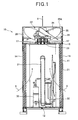
- Fig. 1 is a side cross-sectional view of the outdoor unit 10
- Fig. 2 is a top view showing the internal construction of the outdoor unit 10.
- the outdoor unit 10 has a substantially rectangular parallelepiped box-shaped unit case (housing) 11, and the unit case 11 has a bottom plate 12, support poles 14 extending from the four corners of the bottom plate 12 in the vertical direction, and a front panel 15 ( Fig. 2 ).
- a heat exchanger 21 which is formed so as to be bent in a substantially U-shape in top view is disposed on the bottom plate 12, and an air blower (axial-flow air blower) 22 is disposed at the upper side of the heat exchanger 21.
- the heat exchanger 21 constitutes side surface portions of the unit case 11, and it is disposed so as to extend from the left side surface of the unit case 11 along the back surface and the right side surface thereof.
- the air blower 22 comprises a fan motor 23 disposed above the heat exchanger 21, and a propeller fan (blade wheel) 24 secured to the shaft of the fan motor 23.
- Joint members 16 for joining the neighboring support poles 14 at the position corresponding to the upper end of the heat exchanger 21 are provided between the neighboring support poles 14, and a pair of support frames 17 bridged between the joint members 16 are fixed to the fan motor 23.
- a bell mouth 25 for guiding air at the air suction side of the propeller fan 24 to the air blow-out side of the propeller fan 24 is provided around the propeller fan 24, and the air blow-out opening 25A of the bell mouth 25 is covered by a fan guard (not shown) for preventing a human body or the like from coming into contact with the propeller fan 24.
- a face panel (not shown) is provided around the bell mouth 25 through a heat insulating member 26 such as foamed polystyrene.
- the outdoor unit 10 When the propeller fan 24 is rotated by the fan motor 23, outdoor air is sucked into the unit case 11 from the surrounding of the outdoor unit 10, specifically, from the left, back and right sides of the unit case 11 excluding the front side of the unit case 11 as indicated by arrows X in Fig. 1 , and discharged to the outside through an air blow-out opening 25A of the bell mouth 25 which is provided to the top surface portion of the unit case 11. That is, the outdoor unit 10 is configured as a top blow-out type for blowing out heat-exchanged air from the top surface.
- a compressor (not shown), an accumulator 31, an oil separator 32 and a receiver tank 33 which constitute a part of the refrigerant circuit are provided on the bottom plate 12 in the unit case 11, and refrigerant circuit constituting parts such as valve members such as a four-way valve (not shown) , an expansion valve (not shown), etc. are mounted in the unit case 11 so as to be connected to one another through pipes.
- refrigerant circuit constituting parts such as valve members such as a four-way valve (not shown) , an expansion valve (not shown), etc. are mounted in the unit case 11 so as to be connected to one another through pipes.
- One end sides of the pipes for the refrigerant circuit constituting parts are connected to the indoor unit through the heat exchanger 21, and the other end sides of the pipes for the refrigerant circuit constituting parts are connected to the indoor unit, thereby constructing the refrigerant circuit in which refrigerant is circulated.
- the compressor is disposed at the front side of the unit case 11, and an electrical component box 34 in which various kinds of electrical component units such as a control board, etc. for controlling the air conditioner are arranged is disposed at the upper space of the compressor. Therefore, by detaching the front panel 15, a worker can easily perform a maintenance work for parts in the unit case 11.
- Reference numeral 35 represents a cover plate which is provided at the upper side of the compressor and prevents rain drops from directly impinging against the compressor.
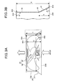
- the bell mouth 25 is formed by resin molding and thus it can be configured to be light in weight and have a desired shape. As shown in Fig. 3A , the bell mouth 25 is configured in a cylindrical shape so as to have an air low-out opening 25A and an air suction opening 25B which is larger in diameter than the air blow-out opening 25A, and also has an air blow-out wall portion 40 which intercommunicates with the air blow-out opening 25A and extends substantially along the axial direction of the propeller fan 24, and a slope wall portion 41 which intercommunicates with the air blow-out wall portion 40 and slopes toward the air suction opening 25B so as to gradually increase in diameter.
- the slope wall portion 41 smoothly feed air in the unit case 11 into the bell mouth 25 when the propeller fan 24 is operated, and it is integrally joined to the air blow-out wall portion 40 by a joint portion 42 as shown in Fig. 3B .
- the slope wall portion 41 expands outwardly toward the air suction opening 25B, and it is formed so as to be bent annularly at a slope angle ⁇ with respect to the plane of the air suction opening 25B.
- the lower end portion (the end portion at the air suction opening side) 41A of the slope wall portion 41 is bent outwardly along the plane of the air suction opening 25B.
- the propeller fan 24 has a hub 45 fixed to the motor shaft of a fanmotor 23 ( Fig. 1 ), and plural blades 46 which are integrally formed on the outer periphery of the hub 45 so as to have a predetermined blade angle and be spaced from one another at predetermined intervals. As shown in Fig. 3A , the propeller fan 24 is disposed so as to be perfectly overlapped with the bell mouth 25 in side view. According to this construction, since the bell mouth 2 5 covers an area where the propeller fan 2 4 operates, all the air blown out by the propeller fan 24 can be guided by the bell mouth 25, so that the air blowing amount of the propeller fan 24 can be enhanced.
- the inventors of this application has performed a simulation to derive shape factors for the bell mouth 25 which can simultaneously satisfy both reduction of the rotational number of the propeller fan 24 and reduction of the load of the fan motor 23 at the same operating point of the air blower 22.
- the same operating point of the air blower 22 means an operating condition that the air flow amount Q (m 3 /min) and the static pressure (mmAq) are equal.
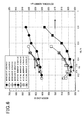
- the abscissa axis represents an air suction port angle, that is, the slope angle ⁇ of the slope wall portion 41 of the bell mouth 25, the ordinate axis at the left side represents a motor load (W) and the ordinate axis at the right side represents the rotational number (rpm) of the propeller fan 24.
- the air blower 22 is operated under the same condition that the air flow amount Q is set to (200m 3 /min) and the static pressure is set to (6mmA), it is simulated how the rotational number of the propeller fan 24 and the load of the fan motor 23 vary while each of the height ratio h/H of the slope wall portion 41 of the bell mouth 25 and the slope angle ⁇ of the slope wall portion 41 is changed.
- the motor load When considered from the viewpoint of the motor load, with respect to bell mouths satisfying h/H - 0.20, 0.33, the motor load has a local minimum point in the neighborhood of the slope angle ⁇ of 60°, and the motor load increases even when the slope angle is smaller and larger than 60°.
- the motor load decreases when the slope angle ⁇ ranges from 50° to 60°, and it is equal to a substantially fixed value when the slope angle ⁇ ranges from 60° to 70°.
- the bell mouth of this embodiment when configured to satisfy 0.33 ⁇ h/H ⁇ 0.42 and 60° ⁇ 70°, it has been found that the bell mouth of this embodiment can satisfy both the reduction of the rotational number of the propeller fan 24 and the reduction of the motor load at the same time with keeping the same air flow amount.
- the motor load and the rotational number trend to increase as the diameter ratio D/d increases. Therefore, in order to reduce the motor load and the rotational number, it is desirable that the value of the diameter ratio D/d is set to be as small as possible. On the other hand, when the value of the diameter ratio D/d is reduced, there occurs a risk that the blades 46 of the propeller fan 24 come into contact with the inner surface of the bell mouth 25.
- the bell mouth and the propeller fan are configured in the range of 1.02 ⁇ D/d ⁇ 1.03, and further it is more desirable that the bell mouth and the propeller fan are configured in the range of 1.0225 ⁇ D/d ⁇ 1.0285.
- the propeller fan 24 is disposed so as to satisfy the range of 0.24 ⁇ hL/h ⁇ 0.40, whereby the rotational number of the propeller fan 24 and the motor load can be further reduced.
- the propeller fan 24 is disposed so as to satisfy the range of 0.866 ⁇ hZ/H ⁇ 0.933, and further the propeller fan 24 is disposed so as to satisfy the range of 0.875 ⁇ hZ/H ⁇ 0.925. Accordingly, the rotational number of the propeller fan 24 and the motor load can be further reduced.
- the bell mouth of this embodiment is configured so as to satisfy 0.33 ⁇ h/H ⁇ 0.42 and 60° ⁇ 70°, the diameter D of the opening of the joint portion 42 of the bell mouth 25 is set to satisfy 1.02 ⁇ D/d ⁇ 1.03, and the propeller fan 24 is disposed in the bell mouth so as to satisfy 0.24 ⁇ hL/h ⁇ 0.40 and 0.866 ⁇ hZ/H ⁇ 0.933, whereby both the reduction of the rotational number of the propeller fan 24 and the reduction of the motor load can be satisfied at the same time with keeping the same air flow amount.
- the propeller fan 24 is disposed so as to be perfectly overlapped with the bell mouth 25 in side view. Therefore, the area where the propeller fan 24 operates is covered by the bell mouth 25, whereby all the air blown by the propeller fan 24 can be guided by the bell mouth 25, and the air flow amount of the propeller fan 24 can be enhanced.
Landscapes
- Engineering & Computer Science (AREA)
- Mechanical Engineering (AREA)
- General Engineering & Computer Science (AREA)
- Chemical & Material Sciences (AREA)
- Combustion & Propulsion (AREA)
- Physics & Mathematics (AREA)
- Fluid Mechanics (AREA)
- Structures Of Non-Positive Displacement Pumps (AREA)
- Other Air-Conditioning Systems (AREA)
Applications Claiming Priority (1)
| Application Number | Priority Date | Filing Date | Title |
|---|---|---|---|
| JP2009270342A JP5322900B2 (ja) | 2009-11-27 | 2009-11-27 | 送風機のベルマウス構造 |
Publications (2)
| Publication Number | Publication Date |
|---|---|
| EP2333435A2 true EP2333435A2 (fr) | 2011-06-15 |
| EP2333435A3 EP2333435A3 (fr) | 2014-11-12 |
Family
ID=43660180
Family Applications (1)
| Application Number | Title | Priority Date | Filing Date |
|---|---|---|---|
| EP10014955.8A Withdrawn EP2333435A3 (fr) | 2009-11-27 | 2010-11-24 | Structure de pavillon de ventilateur |
Country Status (4)
| Country | Link |
|---|---|
| US (1) | US20110127019A1 (fr) |
| EP (1) | EP2333435A3 (fr) |
| JP (1) | JP5322900B2 (fr) |
| CN (1) | CN102080673B (fr) |
Cited By (2)
| Publication number | Priority date | Publication date | Assignee | Title |
|---|---|---|---|---|
| EP2889543A4 (fr) * | 2012-06-07 | 2016-07-20 | Mitsubishi Electric Corp | Unité extérieure de climatisation |
| EP2896897B1 (fr) * | 2012-09-12 | 2022-12-14 | Mitsubishi Electric Corporation | Dispositif à cycle de réfrigération |
Families Citing this family (18)
| Publication number | Priority date | Publication date | Assignee | Title |
|---|---|---|---|---|
| JP5891408B2 (ja) * | 2011-07-15 | 2016-03-23 | パナソニックIpマネジメント株式会社 | 空気調和装置の室外ユニット |
| JP5877364B2 (ja) * | 2011-06-13 | 2016-03-08 | パナソニックIpマネジメント株式会社 | 空気調和装置の室外ユニット |
| JP6385752B2 (ja) * | 2013-12-02 | 2018-09-05 | 三星電子株式会社Samsung Electronics Co.,Ltd. | 送風装置及び空気調和装置用室外機 |
| KR20150075934A (ko) * | 2013-12-26 | 2015-07-06 | 엘지전자 주식회사 | 송풍장치 및 이를 적용한 공기조화기의 실외기. |
| KR102395851B1 (ko) * | 2015-04-08 | 2022-05-10 | 삼성전자주식회사 | 팬 어셈블리 및 이를 포함하는 공기조화기 |
| JP6495860B2 (ja) * | 2016-04-21 | 2019-04-03 | ダイキン工業株式会社 | 熱源ユニット |
| US10648681B2 (en) | 2016-07-19 | 2020-05-12 | Mitsubishi Electric Corporation | Heat source unit and refrigeration cycle apparatus |
| CN106438414B (zh) * | 2016-11-02 | 2019-07-30 | 美的集团股份有限公司 | 风机组件及具有其的生活电器 |
| CN106438413B (zh) * | 2016-11-02 | 2019-07-30 | 美的集团股份有限公司 | 风机组件及具有其的生活电器 |
| CN106368964B (zh) * | 2016-11-02 | 2019-07-30 | 美的集团股份有限公司 | 风机组件及具有其的生活电器 |
| JP6879458B2 (ja) * | 2017-03-15 | 2021-06-02 | 株式会社富士通ゼネラル | 空気調和機の室外機 |
| KR102559756B1 (ko) * | 2018-09-14 | 2023-07-27 | 삼성전자주식회사 | 공기조화기의 실외기 |
| JP7173939B2 (ja) * | 2019-08-26 | 2022-11-16 | ダイキン工業株式会社 | 送風装置及びヒートポンプユニット |
| WO2021084605A1 (fr) | 2019-10-29 | 2021-05-06 | 三菱電機株式会社 | Unité extérieure pour dispositif de climatisation |
| CN113932321A (zh) * | 2020-07-14 | 2022-01-14 | 上海伯涵热能科技有限公司 | 一种高速出风窄立面空调外机 |
| US12459835B2 (en) * | 2021-02-01 | 2025-11-04 | Institute Of Urban Environment, Chinese Academy Of Sciences | Fluidized adsorption device and fluidized adsorption method for sewage treatment |
| US20220325905A1 (en) * | 2021-04-07 | 2022-10-13 | Rheem Manufacturing Company | Air handling unit and fan therefor |
| WO2024014381A1 (fr) * | 2022-07-15 | 2024-01-18 | ダイキン工業株式会社 | Unité de source de chaleur et dispositif de réfrigération |
Citations (1)
| Publication number | Priority date | Publication date | Assignee | Title |
|---|---|---|---|---|
| JP2004211971A (ja) | 2002-12-27 | 2004-07-29 | Daikin Ind Ltd | 空気調和機の室外機 |
Family Cites Families (15)
| Publication number | Priority date | Publication date | Assignee | Title |
|---|---|---|---|---|
| JPS53132011U (fr) * | 1977-03-28 | 1978-10-19 | ||
| KR0140195B1 (ko) * | 1990-03-07 | 1998-07-01 | 다나까 다로오 | 압입식 축류 송풍기 |
| WO2002053919A1 (fr) * | 2000-12-28 | 2002-07-11 | Daikin Industries, Ltd. | Soufflante et unite exterieure pour conditionneur d'air |
| CN2592921Y (zh) * | 2002-07-30 | 2003-12-17 | 倪松涛 | 混流风机 |
| CN2606205Y (zh) * | 2002-12-23 | 2004-03-10 | 余习猛 | 低噪声通风机 |
| JP4627409B2 (ja) * | 2004-04-20 | 2011-02-09 | 日本電産サーボ株式会社 | 軸流ファン |
| CN100455822C (zh) * | 2004-09-06 | 2009-01-28 | 台达电子工业股份有限公司 | 散热风扇及其扇框结构 |
| JP5259919B2 (ja) * | 2005-07-21 | 2013-08-07 | ダイキン工業株式会社 | 軸流ファン |
| JP4577131B2 (ja) * | 2005-07-22 | 2010-11-10 | ダイキン工業株式会社 | 送風装置およびこの送風装置を備えた空気調和機用室外ユニット |
| TWM292888U (en) * | 2005-12-30 | 2006-06-21 | Sheng-An Yang | Heat-dissipating fan |
| JP2007218101A (ja) * | 2006-02-14 | 2007-08-30 | Nippon Densan Corp | 軸流ファンのハウジングおよび軸流ファン |
| CN100554702C (zh) * | 2006-06-09 | 2009-10-28 | 日本电产株式会社 | 轴流风扇 |
| JP2008014302A (ja) * | 2006-06-09 | 2008-01-24 | Nippon Densan Corp | 軸流ファン |
| JP4380744B2 (ja) * | 2007-07-12 | 2009-12-09 | ダイキン工業株式会社 | 送風ユニット |
| CN101576094A (zh) * | 2008-05-07 | 2009-11-11 | 台达电子工业股份有限公司 | 风扇及其导流结构 |
-
2009
- 2009-11-27 JP JP2009270342A patent/JP5322900B2/ja not_active Expired - Fee Related
-
2010
- 2010-11-23 US US12/952,726 patent/US20110127019A1/en not_active Abandoned
- 2010-11-24 EP EP10014955.8A patent/EP2333435A3/fr not_active Withdrawn
- 2010-11-29 CN CN201010563666XA patent/CN102080673B/zh not_active Expired - Fee Related
Patent Citations (1)
| Publication number | Priority date | Publication date | Assignee | Title |
|---|---|---|---|---|
| JP2004211971A (ja) | 2002-12-27 | 2004-07-29 | Daikin Ind Ltd | 空気調和機の室外機 |
Cited By (3)
| Publication number | Priority date | Publication date | Assignee | Title |
|---|---|---|---|---|
| EP2889543A4 (fr) * | 2012-06-07 | 2016-07-20 | Mitsubishi Electric Corp | Unité extérieure de climatisation |
| US9702571B2 (en) | 2012-06-07 | 2017-07-11 | Mitsubishi Electric Corporation | Air conditioner outdoor unit |
| EP2896897B1 (fr) * | 2012-09-12 | 2022-12-14 | Mitsubishi Electric Corporation | Dispositif à cycle de réfrigération |
Also Published As
| Publication number | Publication date |
|---|---|
| CN102080673B (zh) | 2013-05-08 |
| JP2011111998A (ja) | 2011-06-09 |
| CN102080673A (zh) | 2011-06-01 |
| EP2333435A3 (fr) | 2014-11-12 |
| US20110127019A1 (en) | 2011-06-02 |
| JP5322900B2 (ja) | 2013-10-23 |
Similar Documents
| Publication | Publication Date | Title |
|---|---|---|
| EP2333435A2 (fr) | Structure de pavillon de ventilateur | |
| EP3553321B1 (fr) | Entrée de ventilateur cvca | |
| CN202835597U (zh) | 空调装置的室外单元 | |
| CN102141272B (zh) | 空气调节装置的室外单元 | |
| EP2618066A1 (fr) | Soufflante pour unité extérieure, unité extérieure et dispositif à cycle de réfrigération | |
| JP5919513B2 (ja) | 空気調和装置の室外ユニット | |
| US11319961B2 (en) | Centrifugal blower, air conditioner, and refrigeration cycle apparatus | |
| EP1606560B1 (fr) | Unite exterieure de climatiseur encastree | |
| EP2886970B1 (fr) | Unité intérieure de climatiseur | |
| CN101520210A (zh) | 室内埋入型热源机 | |
| EP1243864A2 (fr) | Unité intérieure et conditionneur d'air | |
| JP4859801B2 (ja) | 空気調和装置の室外ユニット | |
| JP2014105901A (ja) | 空気調和機の室外機 | |
| US20160252259A1 (en) | Indoor Unit of Air Conditioner and Air Conditioner Including the Same | |
| EP2096365A1 (fr) | Unité de source de chaleur installée dans un bâtiment | |
| JP2009052856A (ja) | 空気調和機の室外機 | |
| JP5709607B2 (ja) | ファンガード、室外ユニット及び冷凍サイクル装置 | |
| US8967975B2 (en) | Centrifugal air blower and air conditioner | |
| JP2007309632A (ja) | 空気調和機の室外機及び空気調和機 | |
| EP3385627B1 (fr) | Unité extérieure | |
| CN109891101B (zh) | 螺旋桨风扇、室外机和制冷循环装置 | |
| JP2007051790A (ja) | 空調用室内機 | |
| JP2013079595A (ja) | 送風機、室外機及び冷凍サイクル装置 | |
| JP7097973B2 (ja) | 室内機及び冷凍サイクル装置 | |
| KR0128828Y1 (ko) | 에어콘디셔너의 저소음용 하우징 |
Legal Events
| Date | Code | Title | Description |
|---|---|---|---|
| PUAI | Public reference made under article 153(3) epc to a published international application that has entered the european phase |
Free format text: ORIGINAL CODE: 0009012 |
|
| 17P | Request for examination filed |
Effective date: 20101124 |
|
| AK | Designated contracting states |
Kind code of ref document: A2 Designated state(s): AL AT BE BG CH CY CZ DE DK EE ES FI FR GB GR HR HU IE IS IT LI LT LU LV MC MK MT NL NO PL PT RO RS SE SI SK SM TR |
|
| AX | Request for extension of the european patent |
Extension state: BA ME |
|
| RIN1 | Information on inventor provided before grant (corrected) |
Inventor name: NAKAMURA, TAKESHI Inventor name: ABASTARI Inventor name: MASUKAWA, TAKAYUKI Inventor name: YANAGI, HIROFUMI |
|
| PUAL | Search report despatched |
Free format text: ORIGINAL CODE: 0009013 |
|
| AK | Designated contracting states |
Kind code of ref document: A3 Designated state(s): AL AT BE BG CH CY CZ DE DK EE ES FI FR GB GR HR HU IE IS IT LI LT LU LV MC MK MT NL NO PL PT RO RS SE SI SK SM TR |
|
| AX | Request for extension of the european patent |
Extension state: BA ME |
|
| RIC1 | Information provided on ipc code assigned before grant |
Ipc: F24F 1/00 20110101AFI20141007BHEP Ipc: F24F 13/08 20060101ALI20141007BHEP |
|
| RBV | Designated contracting states (corrected) |
Designated state(s): AL AT BE BG CH CY CZ DE DK EE ES FI FR GB GR HR HU IE IS IT LI LT LU LV MC MK MT NL NO PL PT RO RS SE SI SK SM TR |
|
| 17Q | First examination report despatched |
Effective date: 20160829 |
|
| STAA | Information on the status of an ep patent application or granted ep patent |
Free format text: STATUS: EXAMINATION IS IN PROGRESS |
|
| STAA | Information on the status of an ep patent application or granted ep patent |
Free format text: STATUS: THE APPLICATION HAS BEEN WITHDRAWN |
|
| 18W | Application withdrawn |
Effective date: 20170907 |