EP2333437A2 - Structure de fixation pour ligne de communication intérieure/extérieure de climatiseur - Google Patents
Structure de fixation pour ligne de communication intérieure/extérieure de climatiseur Download PDFInfo
- Publication number
- EP2333437A2 EP2333437A2 EP10174187A EP10174187A EP2333437A2 EP 2333437 A2 EP2333437 A2 EP 2333437A2 EP 10174187 A EP10174187 A EP 10174187A EP 10174187 A EP10174187 A EP 10174187A EP 2333437 A2 EP2333437 A2 EP 2333437A2
- Authority
- EP
- European Patent Office
- Prior art keywords
- indoor
- fixing base
- portions
- outdoor
- communication lines
- Prior art date
- Legal status (The legal status is an assumption and is not a legal conclusion. Google has not performed a legal analysis and makes no representation as to the accuracy of the status listed.)
- Granted
Links
Images


Classifications
-
- F—MECHANICAL ENGINEERING; LIGHTING; HEATING; WEAPONS; BLASTING
- F24—HEATING; RANGES; VENTILATING
- F24F—AIR-CONDITIONING; AIR-HUMIDIFICATION; VENTILATION; USE OF AIR CURRENTS FOR SCREENING
- F24F1/00—Room units for air-conditioning, e.g. separate or self-contained units or units receiving primary air from a central station
- F24F1/0003—Room units for air-conditioning, e.g. separate or self-contained units or units receiving primary air from a central station characterised by a split arrangement, wherein parts of the air-conditioning system, e.g. evaporator and condenser, are in separately located units
-
- F—MECHANICAL ENGINEERING; LIGHTING; HEATING; WEAPONS; BLASTING
- F24—HEATING; RANGES; VENTILATING
- F24F—AIR-CONDITIONING; AIR-HUMIDIFICATION; VENTILATION; USE OF AIR CURRENTS FOR SCREENING
- F24F1/00—Room units for air-conditioning, e.g. separate or self-contained units or units receiving primary air from a central station
- F24F1/06—Separate outdoor units, e.g. outdoor unit to be linked to a separate room comprising a compressor and a heat exchanger
- F24F1/20—Electric components for separate outdoor units
- F24F1/22—Arrangement or mounting thereof
-
- F—MECHANICAL ENGINEERING; LIGHTING; HEATING; WEAPONS; BLASTING
- F24—HEATING; RANGES; VENTILATING
- F24F—AIR-CONDITIONING; AIR-HUMIDIFICATION; VENTILATION; USE OF AIR CURRENTS FOR SCREENING
- F24F11/00—Control or safety arrangements
- F24F11/50—Control or safety arrangements characterised by user interfaces or communication
- F24F11/54—Control or safety arrangements characterised by user interfaces or communication using one central controller connected to several sub-controllers
-
- F—MECHANICAL ENGINEERING; LIGHTING; HEATING; WEAPONS; BLASTING
- F24—HEATING; RANGES; VENTILATING
- F24F—AIR-CONDITIONING; AIR-HUMIDIFICATION; VENTILATION; USE OF AIR CURRENTS FOR SCREENING
- F24F13/00—Details common to, or for air-conditioning, air-humidification, ventilation or use of air currents for screening
- F24F13/20—Casings or covers
- F24F2013/207—Casings or covers with control knobs; Mounting controlling members or control units therein
Definitions
- the present invention relates to a fixing structure for an indoor/outdoor communication line connecting an outdoor unit and indoor units to each other in a multi-unit type air conditioner in which a plurality of indoor units are connected to one outdoor unit.
- Fig. 10 is a perspective view illustrating a state in which a sectional panel of an outdoor unit of a prior-art air conditioner is removed
- Fig. 11 is a front view around an electric-component mounting base in Fig. 10
- Fig. 12 is a side view of an essential part of Fig. 11 .
- a compressor 72 and a pipeline 73 are installed at a lower part, while an electric-component mounting base 74 is disposed at an upper part, and a machine chamber 71 is provided in which a plurality of terminal blocks 75a to 75n corresponding to each of the indoor units and electric components and the like are disposed.
- Reference numeral 78 denotes a heat exchanger installed from the other side face to the rear face of the machine chamber 71 and reference numeral 79 denotes a front panel having an outlet grill (not shown) and covering a front face and the other side face, and between the heat exchanger 78 and the front panel 79, an air-blowing chamber 81 in which a blower and the like are installed is disposed having a partition plate 80 between that and the machine chamber 71.
- such a cable holding structure includes a receiving fixture formed in a stepped shape and having a long hole through which a cable is inserted in a predetermined direction and a pressing fixture having a plurality of U-shaped bent portions mounted to the face of the receiving fixture, respectively, in which the cable inserted through the long hole is sandwiched between the receiving fixture and the U-shaped bent portions of the pressing fixture so as to be fixed (See Patent Literature 1, for example).
- each of the pressing fixtures 77a to 77c needs an installation space for one or two of the indoor/outdoor communication lines 76a to 76n connected to each of the terminal blocks 75a to 75n, therefore, it was difficult to install the plurality of indoor/outdoor communication lines 76a to 76n in a small space.
- the present invention was made in order to solve the above problems and an object thereof is to provide a fixing structure for an indoor/outdoor communication line of an air conditioner which can efficiently fix a plurality of indoor/outdoor communication lines connected to terminal blocks even in a small space and is inexpensive and excellent in assembling performance and serviceability.
- a fixing structure for an indoor/outdoor communication line of an air conditioner according to the present invention fixes, in a multi-unit type air conditioner in which a plurality of indoor units are connected to one outdoor unit through a plurality of indoor/outdoor communication lines, the plurality of indoor/outdoor communication lines are fixed in a bundle to a main body of the outdoor unit by a communication-line fixture.
- the plurality of indoor/outdoor communication lines can be fixed to the main body of the outdoor unit efficiently in a bundle by the communication-line fixture, a fixing structure for an indoor/outdoor communication line which is inexpensive and excellent in assembling performance and serviceability even in a small space can be obtained.
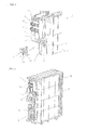
- Fig. 1 is an explanatory diagram of a fixing structure for an indoor/outdoor communication line of an air conditioner according to Embodiment 1 of the present invention
- Fig. 2 is a partially omitted perspective view of an outdoor unit of the air conditioner
- Fig. 3 is a front view of an electric-component mounting portion in Fig. 2
- a compressor not shown
- a pipeline 3 and the like are disposed
- an electric-component mounting portion 4 is disposed at an upper part.
- Reference numeral 8 denotes a heat exchanger disposed from the rear face to the other side face
- reference numeral 9 denotes a partition plate partitioning the machine chamber 2 from an adjacent air-blowing chamber.
- an electric component 5 and the like are disposed, and a plurality of terminal blocks 6a to 6f (hereinafter referred to simply as 6 in some cases) are installed below that.
- a plurality of terminal blocks 6a to 6f (hereinafter referred to simply as 6 in some cases) are installed below that.
- the other end of each of a plurality of indoor/outdoor communication lines 7a to 7f (hereinafter referred to simply as a communication line or might be indicated by reference numeral 7 in a bundle) having one end connected to each of indoor units (not shown) is connected, and the plurality of communication lines 7a to 7f are fixed to a main body (the partition plate 9 in this case) of the outdoor unit 1 in a bundle by a communication-line fixture 10.
- Fig. 4 is an explanatory diagram illustrating a state in which the plurality of communication lines 7 are fixed in a bundle by the communication-line fixture 10
- Fig. 5 is an exploded perspective view of the communication-line fixture 10 in Fig. 4 .
- the communication-line fixture 10 includes, as shown in Fig. 5 , a fixing base 11, a receiver 20, and a presser 30. They will be described below in detail.
- the fixing base 11 has recess-shaped first and second holding portions 12a and 12b that hold the communication line 7 and screw insertion holes 14 and is constituted by fixing portions 13a to 13c disposed between the both holding portions 12a and 12b and at positions higher than the holding portions 12a and 12b on both sides and having the screw insertion holes 14, mounting pieces 15a and 15b extended downward from outer walls of the fixing portions 13b and 13c on both sides and then, folded outward and having screw insertion holes 16, and supporting pieces 17a and 17b extended downward from both sides of the holding portions 12a and 12b and then, folded outward.
- the receiver 20 is formed having the length substantially equal to the length between the outer walls of the both fixing portions 13b and 13c of the fixing base 11 and the width substantially equal to the width of the fixing base 11 and has a main body portion 21 in which both end portions in the longitudinal direction are folded downward and engagement pieces 23a and 23b are disposed. At positions corresponding to the fixing portions 13a to 13c of the fixing base 11 on both-side edges of the main body portion 21, sandwiching portions 24a to 24c folded upward are disposed, respectively, and first and second receiving portions 25a and 25b for the communication lines 7 are disposed between the sandwiching portions 24a and 24b and between the sandwiching portions 24a and 24c.
- screw insertions hole 22 (the screw insertion holes 22 on the both sides are long holes) are disposed corresponding to the screw insertion holes 14 disposed in the fixing portions 13a to 13c of the fixing base 11.
- the presser 30 is formed having the length substantially equal to the length of a receiving plate 21 of the receiver 20 and the width substantially equal to an interval between inner walls of the opposing sandwiching portions 24a to 24c of the receiver 20.
- Projection-shaped first and second pressing portions 31a and 31b are disposed corresponding to the receiving portions 25a and 25b of the receiver 20, and between the pressing portions 31a and 31b and in the both end portions, mounting portions 32a to 32b which are folded downward from the pressing portions 31a and 31b and form flat portions are disposed corresponding to the sandwiching portions 24a to 24c of the receiver 20, and a screw insertion hole 33 is disposed in the flat portion of each of the mounting portions 32a to 32b corresponding to the screw insertion holes 22 of the receiver 20.
- the plurality of indoor/outdoor communication lines 7 connected to the terminal blocks 6 ( Fig. 4 shows the case of the communication lines 7e, 7f, and 7n) are placed on the holding portions 12a and 12b of the fixing base 11, the receiver 20 is placed on top of it, and the engagement pieces 23a and 23b are fitted with the both side walls of the fixing portions 13a and 13b of the fixing base 11.
- the communication lines 7 are sandwiched between the holding portions 12a and 12b of the fixing base 11 and the receiving portions 25a and 25b of the receiver 20.
- the plurality of communication lines 7 (the case of the communication lines 7b, 7c, 7a, and 7d is shown in Fig. 4 ) are placed on the receiving portions 25a and 25b of the receiver 20.
- the presser 30 is fitted between the sandwiching portions 24a to 24c from above the receiver 20 so that the communication lines 7 are sandwiched between the receiving portions 25a and 25b of the receiver 20 and the pressing portions 31a and 31b of the presser 30.
- screws 35 which are fixing member, are inserted through the screw insertion holes 33, 22, and 14 disposed in the presser 30, the receiver 20, and the fixing base 11, screwed into nuts 36 disposed on the rear faces of the fixing portions 13a to 13c of the fixing base 11 and integrally fixed.
- the case in which the screw 35 is screwed into the nut 36 disposed on the rear face of the fixing base 11 is shown, but the nut may be omitted and the screw insertion hole 14 of the fixing base 11 is used as a screw hole, through which the screw 35 may be screwed into.
- the plurality of indoor/outdoor communication lines 7 are bundled by the communication-line fixture 10 and fixed to the main body of the outdoor unit 1. Also, if each of the communication lines 7 is to be removed for maintenance or the like, the communication line can be easily taken out by loosening the screw 35 of the communication-line fixture 10 and by removing the presser 30 or the presser 30 and the receiver 20.
- the plurality of indoor/outdoor communication lines 7 having one ends connected to the indoor units and the other ends to the terminal blocks 6 of the outdoor unit are stacked in double by the communication-line fixture 10 and fixed to the main body of the outdoor unit 1 collectively, the large number of communication lines 7 can be easily fixed even in a small space, and assembling performances and serviceability can be improved.
- Fig. 6 is an explanatory diagram of a fixing structure for an indoor/outdoor communication line of an air conditioner according to Embodiment 2 of the present invention
- Fig. 7 is an explanatory diagram illustrating a state in which a plurality of indoor/outdoor communication lines are fixed in a bundle by a communication-line fixture in Fig. 6
- Fig. 8 is an exploded perspective view of the communication-line fixture in Fig. 7 .
- the same reference numerals are given to the same portions as those in Embodiment 1.
- the communication-line fixture 10 is formed by a fixing base 40, a plurality of pressers 50, and a receiver 60.
- the fixing base 40 has a main body portion 41 having a substantially U-shaped section, in which free ends of both-side plates are folded outward and provided with mounting pieces 43a and 43b having screw insertion holes 44a and 44b, and receiving portions 42a and 42b for the first and second communication lines 7 are disposed on the top face.
- screw insertion holes 45a and 45b are disposed vertically, and the two screw insertion holes 45a and 45b are arranged side by side between the receiving portions 42a and 42b.
- respective screw insertion holes 46 are disposed.
- Each of the pressers 50 is formed having a length substantially half of that of the length of the fixing base 40 and the width smaller than the width of the main body portion 41.
- a projection-shaped pressing portion 51 is disposed corresponding to the one receiving portions 42a (or 42b) of the fixing base 40, and the both end portions of the pressing portion 51 are folded downward and then folded outward, and mounting pieced 52a and 52b in which screw insertion holes 53 are disposed are provided.
- the pressers 50 in the same structure are used in plural (the case of four pressers is shown in the figure).
- the receiver 60 has a main body portion 61 having a substantially U-shaped section formed having the length substantially equal to the length of the fixing base 40 and the width formed slightly larger than the width of the presser 50, fixing pieces 63a to 63c extended downward from both end portions and the center part in the longitudinal direction of the both side walls of the main body portion 61 and then, folded outward are disposed, and screw insertion holes 64 corresponding to the screw insertion holes 46 of the fixing base 40 are disposed in the fixing pieces 63a and 63b on the both end portions.
- Receiving portions 62a and 62b for the first and second communication lines 7 are disposed on the top face, and screw insertion holes 65a and 65b are disposed at positions corresponding to the screw insertion holes 45a and 45b of the fixing base 40 at the center part in the width direction of the top face.
- the mounting pieces 43a and 43b of the fixing base 10 are brought into contact with the predetermined positions on the main body (the partition plate 9 in this case) of the outdoor unit 1, the screw inserted through the screw insertion holes 44a and 44b are screwed into the partition plate 9, and the fixing base 10 is fixed.
- one or two communication lines 7 are placed on the one receiving portion 42a (or 42b) of the fixing base 40, the top thereof is covered by the presser 50a, the mounting pieces 52a and 52b are brought into contact with the top face of the fixing base 40, and the screw inserted through the screw insertion holes 53 of the mounting pieces 52a and 52b are inserted through the screw insertion holes 45a, screwed into nuts disposed on the rear face and fixed.
- the communication lines 7 are sandwiched between the fixing base 40 and the presser 50a and fixed.
- the communication lines 7 are placed on the other receiving portion 42b of the fixing base 40, sandwiched between the presser 50b and the fixing base 40 and fixed (the pressers 50a and 50b might be described as first pressers).
- the receiver 60 is fitted with the both pressers 50a and 50b from above, and the fixing pieces 63a to 63c are brought into contact with the top face of the fixing base 40. Then, the screws inserted through the screw holes 64 disposed in the fixing pieces 63a and 63b are inserted through the screw insertion holes 46 of the fixing base 40 and screwed into the nuts disposed on the rear face and fixed.
- the communication lines 7 are placed on the one receiving portion 62a (or 62b) on the top face of the receiver 60 and sandwiched and fixed by the presser 50c in the same way as the above. Also, in the same way, the communication lines 7 placed on the other receiving portion 62b are sandwiched by the presser 50d and fixed (the pressers 50c and 50d may be described as second pressers). As a result, the plurality of communication lines 7 are fixed by the communication-line fixture 10 collectively.
Landscapes
- Engineering & Computer Science (AREA)
- Chemical & Material Sciences (AREA)
- Combustion & Propulsion (AREA)
- Mechanical Engineering (AREA)
- General Engineering & Computer Science (AREA)
- Other Air-Conditioning Systems (AREA)
- Air Filters, Heat-Exchange Apparatuses, And Housings Of Air-Conditioning Units (AREA)
- Air Conditioning Control Device (AREA)
Applications Claiming Priority (1)
| Application Number | Priority Date | Filing Date | Title |
|---|---|---|---|
| JP2009274244A JP5084816B2 (ja) | 2009-12-02 | 2009-12-02 | 空気調和機の内外通信線固定構造 |
Publications (3)
| Publication Number | Publication Date |
|---|---|
| EP2333437A2 true EP2333437A2 (fr) | 2011-06-15 |
| EP2333437A3 EP2333437A3 (fr) | 2015-03-25 |
| EP2333437B1 EP2333437B1 (fr) | 2018-03-21 |
Family
ID=43608157
Family Applications (1)
| Application Number | Title | Priority Date | Filing Date |
|---|---|---|---|
| EP10174187.4A Not-in-force EP2333437B1 (fr) | 2009-12-02 | 2010-08-26 | Structure de fixation pour ligne de communication intérieure/extérieure de climatiseur |
Country Status (6)
| Country | Link |
|---|---|
| US (1) | US20110126567A1 (fr) |
| EP (1) | EP2333437B1 (fr) |
| JP (1) | JP5084816B2 (fr) |
| CN (1) | CN102087043B (fr) |
| AU (1) | AU2010212358B2 (fr) |
| ES (1) | ES2666666T3 (fr) |
Cited By (1)
| Publication number | Priority date | Publication date | Assignee | Title |
|---|---|---|---|---|
| EP2966377A1 (fr) * | 2014-07-07 | 2016-01-13 | Mitsubishi Electric Corporation | Dispositif de fixation de fils de connexion, boîtier de composant électrique utilisant ce dispositif, unité intérieure de climatiseur |
Families Citing this family (12)
| Publication number | Priority date | Publication date | Assignee | Title |
|---|---|---|---|---|
| KR101845563B1 (ko) * | 2011-10-21 | 2018-05-18 | 엘지전자 주식회사 | 공기 조화기가 구비되는 네트워크 시스템 및 그 제어방법 |
| US9528747B2 (en) | 2012-06-07 | 2016-12-27 | Samsung Electronics Co., Ltd. | Refrigerator |
| USD785151S1 (en) * | 2014-08-13 | 2017-04-25 | Atm Beyaz Esya Parcalari Sanayi Ve Ticaret Limited Sirketi | Condenser |
| JP6453589B2 (ja) * | 2014-08-29 | 2019-01-16 | 株式会社コロナ | ヒートポンプ装置 |
| USD783790S1 (en) | 2014-09-26 | 2017-04-11 | Toshiba Carrier Corporation | Heat exchanger for an air conditioner |
| JP6481594B2 (ja) * | 2015-11-26 | 2019-03-13 | 株式会社富士通ゼネラル | 空気調和機の室外機 |
| JP6481863B2 (ja) * | 2015-12-18 | 2019-03-13 | 株式会社富士通ゼネラル | 空気調和機の室外機 |
| JP6569513B2 (ja) * | 2015-12-21 | 2019-09-04 | 株式会社富士通ゼネラル | 空気調和機の室外機 |
| JP6790685B2 (ja) * | 2016-09-30 | 2020-11-25 | 株式会社富士通ゼネラル | 空気調和機の室外機 |
| US20220120450A1 (en) * | 2018-10-29 | 2022-04-21 | Ftl, Inc. | Saddle air conditioner |
| JP2022086630A (ja) * | 2020-11-30 | 2022-06-09 | 株式会社富士通ゼネラル | 空気調和機の室外機 |
| CN114017854B (zh) * | 2021-12-09 | 2024-01-23 | 任以超 | 一种操作方便且稳定高的空调安装架体 |
Citations (1)
| Publication number | Priority date | Publication date | Assignee | Title |
|---|---|---|---|---|
| JPH0187586U (fr) | 1987-12-01 | 1989-06-09 |
Family Cites Families (20)
| Publication number | Priority date | Publication date | Assignee | Title |
|---|---|---|---|---|
| US325767A (en) * | 1885-09-08 | Thomas w | ||
| US770278A (en) * | 1904-05-14 | 1904-09-20 | John R Fletcher | Insulation-rack. |
| JPH02273998A (ja) * | 1989-04-17 | 1990-11-08 | Fujitsu Ltd | ケーブル支持構造 |
| JP3213494B2 (ja) * | 1994-11-30 | 2001-10-02 | 三洋電機株式会社 | 空気調和機の電気配線接続装置 |
| US5996945A (en) * | 1997-10-31 | 1999-12-07 | Caterpillar Inc. | Hose clamp assembly offset mounting capability |
| US6561466B1 (en) * | 2002-02-20 | 2003-05-13 | Mitchell W. Myers | Interchangeable hose, cable, and conduit support mechanism |
| JP2004147370A (ja) * | 2002-10-22 | 2004-05-20 | Yazaki Corp | 配線ユニットケーブル配列治具 |
| CN1590895A (zh) * | 2003-08-25 | 2005-03-09 | 乐金电子(天津)电器有限公司 | 一机多端型空气调节器的连接阀组件 |
| USD537332S1 (en) * | 2004-05-06 | 2007-02-27 | Nagle Christopher N | Two-tube “C” bracket |
| JP4357374B2 (ja) * | 2004-06-28 | 2009-11-04 | ポップリベット・ファスナー株式会社 | パイプ等の耐熱性クランプ装置 |
| JP4353927B2 (ja) * | 2005-07-21 | 2009-10-28 | 矢崎総業株式会社 | フラットケーブル結束ホルダー |
| WO2007078288A2 (fr) * | 2005-12-30 | 2007-07-12 | Carrier Corporation | Dispositif de retenue de cables |
| SE0600367L (sv) * | 2006-02-17 | 2007-08-18 | Roxtec Ab | Kabelfasthållningsanordning |
| JP4721943B2 (ja) * | 2006-04-04 | 2011-07-13 | 三洋電機株式会社 | 空気調和装置の室外機 |
| JP2008020132A (ja) * | 2006-07-13 | 2008-01-31 | Daikin Ind Ltd | 空気調和機の室外機 |
| GB0624617D0 (en) * | 2006-12-11 | 2007-01-17 | Tyco Electronics Raychem Nv | Cable Retention Clip |
| JP4889508B2 (ja) * | 2007-01-16 | 2012-03-07 | 三菱電機株式会社 | 空気調和機の配管継ぎ手取り付け構造 |
| SE531217C2 (sv) * | 2007-05-29 | 2009-01-20 | Roxtec Ab | Kabelgenomföring |
| US8291551B2 (en) * | 2009-04-22 | 2012-10-23 | Deere & Company | Clamp assembly |
| US8596589B2 (en) * | 2009-06-09 | 2013-12-03 | Syntiro Dynamics Llc | Attachable grommets for hanging pipes |
-
2009
- 2009-12-02 JP JP2009274244A patent/JP5084816B2/ja not_active Expired - Fee Related
-
2010
- 2010-08-12 US US12/854,940 patent/US20110126567A1/en not_active Abandoned
- 2010-08-13 AU AU2010212358A patent/AU2010212358B2/en not_active Ceased
- 2010-08-26 ES ES10174187.4T patent/ES2666666T3/es active Active
- 2010-08-26 EP EP10174187.4A patent/EP2333437B1/fr not_active Not-in-force
- 2010-09-17 CN CN201010287830.9A patent/CN102087043B/zh not_active Expired - Fee Related
Patent Citations (1)
| Publication number | Priority date | Publication date | Assignee | Title |
|---|---|---|---|---|
| JPH0187586U (fr) | 1987-12-01 | 1989-06-09 |
Cited By (1)
| Publication number | Priority date | Publication date | Assignee | Title |
|---|---|---|---|---|
| EP2966377A1 (fr) * | 2014-07-07 | 2016-01-13 | Mitsubishi Electric Corporation | Dispositif de fixation de fils de connexion, boîtier de composant électrique utilisant ce dispositif, unité intérieure de climatiseur |
Also Published As
| Publication number | Publication date |
|---|---|
| ES2666666T3 (es) | 2018-05-07 |
| EP2333437A3 (fr) | 2015-03-25 |
| CN102087043B (zh) | 2014-11-19 |
| CN102087043A (zh) | 2011-06-08 |
| EP2333437B1 (fr) | 2018-03-21 |
| AU2010212358A1 (en) | 2011-06-16 |
| US20110126567A1 (en) | 2011-06-02 |
| JP5084816B2 (ja) | 2012-11-28 |
| JP2011117644A (ja) | 2011-06-16 |
| AU2010212358B2 (en) | 2012-11-29 |
Similar Documents
| Publication | Publication Date | Title |
|---|---|---|
| EP2333437B1 (fr) | Structure de fixation pour ligne de communication intérieure/extérieure de climatiseur | |
| US7918101B2 (en) | Outdoor unit of air conditioner | |
| EP2865954B1 (fr) | Unité extérieure pour appareil de conditionnement d'air | |
| US10371371B2 (en) | Ventilation kit and recessed light fixture assembly with ventilation | |
| EP1296434B1 (fr) | Structure d'alimentation de puissance pour un dispositif de communication | |
| JP7112163B2 (ja) | 空気調和装置の室外機 | |
| US7798451B2 (en) | Three-in-one door bracket | |
| JP6481594B2 (ja) | 空気調和機の室外機 | |
| JP5994323B2 (ja) | 空気調和機の室外機 | |
| KR20230009586A (ko) | 배전반용 프레임 구조체 | |
| WO2013130801A1 (fr) | Tableau de connexions et procédé pour faciliter l'accès aux ports arrière d'un composant | |
| EP1750338B1 (fr) | Elément séparateur métallique pour chemin de câble en treillis et chemin de câble en treillis comportant cet element | |
| CN101432586A (zh) | 线保持器 | |
| JP2022089284A (ja) | 空気調和機の室外機 | |
| JP2001193969A (ja) | 空気調和装置用ファンモータ取付台及び空気調和装置 | |
| CN115157963A (zh) | 接线盒组件以及包含其的驻车空调 | |
| JP4796208B1 (ja) | ライティングダクト | |
| CN205351546U (zh) | 空调室内机 | |
| JP2018054251A (ja) | 空気調和機の室外機 | |
| CN215295161U (zh) | 一种电辅热模块、空调室内机及风管式空调器 | |
| JP7600645B2 (ja) | 空気調和機の室外機 | |
| JP7534713B2 (ja) | 空気調和機の室外機 | |
| CN224065601U (zh) | 机壳组件、室外机和暖通设备 | |
| JP2000205608A (ja) | 空気調和機 | |
| CN205783436U (zh) | 面板组件及除湿机 |
Legal Events
| Date | Code | Title | Description |
|---|---|---|---|
| PUAI | Public reference made under article 153(3) epc to a published international application that has entered the european phase |
Free format text: ORIGINAL CODE: 0009012 |
|
| AK | Designated contracting states |
Kind code of ref document: A2 Designated state(s): AL AT BE BG CH CY CZ DE DK EE ES FI FR GB GR HR HU IE IS IT LI LT LU LV MC MK MT NL NO PL PT RO SE SI SK SM TR |
|
| AX | Request for extension of the european patent |
Extension state: BA ME RS |
|
| PUAL | Search report despatched |
Free format text: ORIGINAL CODE: 0009013 |
|
| AK | Designated contracting states |
Kind code of ref document: A3 Designated state(s): AL AT BE BG CH CY CZ DE DK EE ES FI FR GB GR HR HU IE IS IT LI LT LU LV MC MK MT NL NO PL PT RO SE SI SK SM TR |
|
| AX | Request for extension of the european patent |
Extension state: BA ME RS |
|
| RIC1 | Information provided on ipc code assigned before grant |
Ipc: F24F 1/22 20110101ALI20150213BHEP Ipc: F24F 1/00 20110101AFI20150213BHEP Ipc: F24F 11/00 20060101ALI20150213BHEP |
|
| 17P | Request for examination filed |
Effective date: 20150716 |
|
| RBV | Designated contracting states (corrected) |
Designated state(s): AL AT BE BG CH CY CZ DE DK EE ES FI FR GB GR HR HU IE IS IT LI LT LU LV MC MK MT NL NO PL PT RO SE SI SK SM TR |
|
| STAA | Information on the status of an ep patent application or granted ep patent |
Free format text: STATUS: EXAMINATION IS IN PROGRESS |
|
| 17Q | First examination report despatched |
Effective date: 20170222 |
|
| GRAP | Despatch of communication of intention to grant a patent |
Free format text: ORIGINAL CODE: EPIDOSNIGR1 |
|
| STAA | Information on the status of an ep patent application or granted ep patent |
Free format text: STATUS: GRANT OF PATENT IS INTENDED |
|
| INTG | Intention to grant announced |
Effective date: 20171115 |
|
| GRAS | Grant fee paid |
Free format text: ORIGINAL CODE: EPIDOSNIGR3 |
|
| GRAA | (expected) grant |
Free format text: ORIGINAL CODE: 0009210 |
|
| STAA | Information on the status of an ep patent application or granted ep patent |
Free format text: STATUS: THE PATENT HAS BEEN GRANTED |
|
| AK | Designated contracting states |
Kind code of ref document: B1 Designated state(s): AL AT BE BG CH CY CZ DE DK EE ES FI FR GB GR HR HU IE IS IT LI LT LU LV MC MK MT NL NO PL PT RO SE SI SK SM TR |
|
| REG | Reference to a national code |
Ref country code: GB Ref legal event code: FG4D |
|
| REG | Reference to a national code |
Ref country code: CH Ref legal event code: EP |
|
| REG | Reference to a national code |
Ref country code: AT Ref legal event code: REF Ref document number: 981527 Country of ref document: AT Kind code of ref document: T Effective date: 20180415 |
|
| REG | Reference to a national code |
Ref country code: IE Ref legal event code: FG4D |
|
| REG | Reference to a national code |
Ref country code: DE Ref legal event code: R096 Ref document number: 602010049265 Country of ref document: DE |
|
| REG | Reference to a national code |
Ref country code: ES Ref legal event code: FG2A Ref document number: 2666666 Country of ref document: ES Kind code of ref document: T3 Effective date: 20180507 |
|
| REG | Reference to a national code |
Ref country code: FR Ref legal event code: PLFP Year of fee payment: 9 |
|
| REG | Reference to a national code |
Ref country code: NL Ref legal event code: MP Effective date: 20180321 |
|
| PG25 | Lapsed in a contracting state [announced via postgrant information from national office to epo] |
Ref country code: CY Free format text: LAPSE BECAUSE OF FAILURE TO SUBMIT A TRANSLATION OF THE DESCRIPTION OR TO PAY THE FEE WITHIN THE PRESCRIBED TIME-LIMIT Effective date: 20180321 Ref country code: LT Free format text: LAPSE BECAUSE OF FAILURE TO SUBMIT A TRANSLATION OF THE DESCRIPTION OR TO PAY THE FEE WITHIN THE PRESCRIBED TIME-LIMIT Effective date: 20180321 Ref country code: HR Free format text: LAPSE BECAUSE OF FAILURE TO SUBMIT A TRANSLATION OF THE DESCRIPTION OR TO PAY THE FEE WITHIN THE PRESCRIBED TIME-LIMIT Effective date: 20180321 Ref country code: FI Free format text: LAPSE BECAUSE OF FAILURE TO SUBMIT A TRANSLATION OF THE DESCRIPTION OR TO PAY THE FEE WITHIN THE PRESCRIBED TIME-LIMIT Effective date: 20180321 Ref country code: NO Free format text: LAPSE BECAUSE OF FAILURE TO SUBMIT A TRANSLATION OF THE DESCRIPTION OR TO PAY THE FEE WITHIN THE PRESCRIBED TIME-LIMIT Effective date: 20180621 |
|
| REG | Reference to a national code |
Ref country code: LT Ref legal event code: MG4D |
|
| REG | Reference to a national code |
Ref country code: AT Ref legal event code: MK05 Ref document number: 981527 Country of ref document: AT Kind code of ref document: T Effective date: 20180321 |
|
| PG25 | Lapsed in a contracting state [announced via postgrant information from national office to epo] |
Ref country code: BG Free format text: LAPSE BECAUSE OF FAILURE TO SUBMIT A TRANSLATION OF THE DESCRIPTION OR TO PAY THE FEE WITHIN THE PRESCRIBED TIME-LIMIT Effective date: 20180621 Ref country code: GR Free format text: LAPSE BECAUSE OF FAILURE TO SUBMIT A TRANSLATION OF THE DESCRIPTION OR TO PAY THE FEE WITHIN THE PRESCRIBED TIME-LIMIT Effective date: 20180622 Ref country code: LV Free format text: LAPSE BECAUSE OF FAILURE TO SUBMIT A TRANSLATION OF THE DESCRIPTION OR TO PAY THE FEE WITHIN THE PRESCRIBED TIME-LIMIT Effective date: 20180321 Ref country code: SE Free format text: LAPSE BECAUSE OF FAILURE TO SUBMIT A TRANSLATION OF THE DESCRIPTION OR TO PAY THE FEE WITHIN THE PRESCRIBED TIME-LIMIT Effective date: 20180321 |
|
| PG25 | Lapsed in a contracting state [announced via postgrant information from national office to epo] |
Ref country code: AL Free format text: LAPSE BECAUSE OF FAILURE TO SUBMIT A TRANSLATION OF THE DESCRIPTION OR TO PAY THE FEE WITHIN THE PRESCRIBED TIME-LIMIT Effective date: 20180321 Ref country code: PL Free format text: LAPSE BECAUSE OF FAILURE TO SUBMIT A TRANSLATION OF THE DESCRIPTION OR TO PAY THE FEE WITHIN THE PRESCRIBED TIME-LIMIT Effective date: 20180321 Ref country code: NL Free format text: LAPSE BECAUSE OF FAILURE TO SUBMIT A TRANSLATION OF THE DESCRIPTION OR TO PAY THE FEE WITHIN THE PRESCRIBED TIME-LIMIT Effective date: 20180321 Ref country code: RO Free format text: LAPSE BECAUSE OF FAILURE TO SUBMIT A TRANSLATION OF THE DESCRIPTION OR TO PAY THE FEE WITHIN THE PRESCRIBED TIME-LIMIT Effective date: 20180321 Ref country code: EE Free format text: LAPSE BECAUSE OF FAILURE TO SUBMIT A TRANSLATION OF THE DESCRIPTION OR TO PAY THE FEE WITHIN THE PRESCRIBED TIME-LIMIT Effective date: 20180321 |
|
| PG25 | Lapsed in a contracting state [announced via postgrant information from national office to epo] |
Ref country code: CZ Free format text: LAPSE BECAUSE OF FAILURE TO SUBMIT A TRANSLATION OF THE DESCRIPTION OR TO PAY THE FEE WITHIN THE PRESCRIBED TIME-LIMIT Effective date: 20180321 Ref country code: SK Free format text: LAPSE BECAUSE OF FAILURE TO SUBMIT A TRANSLATION OF THE DESCRIPTION OR TO PAY THE FEE WITHIN THE PRESCRIBED TIME-LIMIT Effective date: 20180321 Ref country code: SM Free format text: LAPSE BECAUSE OF FAILURE TO SUBMIT A TRANSLATION OF THE DESCRIPTION OR TO PAY THE FEE WITHIN THE PRESCRIBED TIME-LIMIT Effective date: 20180321 Ref country code: AT Free format text: LAPSE BECAUSE OF FAILURE TO SUBMIT A TRANSLATION OF THE DESCRIPTION OR TO PAY THE FEE WITHIN THE PRESCRIBED TIME-LIMIT Effective date: 20180321 |
|
| PG25 | Lapsed in a contracting state [announced via postgrant information from national office to epo] |
Ref country code: PT Free format text: LAPSE BECAUSE OF FAILURE TO SUBMIT A TRANSLATION OF THE DESCRIPTION OR TO PAY THE FEE WITHIN THE PRESCRIBED TIME-LIMIT Effective date: 20180723 |
|
| REG | Reference to a national code |
Ref country code: DE Ref legal event code: R097 Ref document number: 602010049265 Country of ref document: DE |
|
| PLBE | No opposition filed within time limit |
Free format text: ORIGINAL CODE: 0009261 |
|
| STAA | Information on the status of an ep patent application or granted ep patent |
Free format text: STATUS: NO OPPOSITION FILED WITHIN TIME LIMIT |
|
| PG25 | Lapsed in a contracting state [announced via postgrant information from national office to epo] |
Ref country code: DK Free format text: LAPSE BECAUSE OF FAILURE TO SUBMIT A TRANSLATION OF THE DESCRIPTION OR TO PAY THE FEE WITHIN THE PRESCRIBED TIME-LIMIT Effective date: 20180321 |
|
| 26N | No opposition filed |
Effective date: 20190102 |
|
| REG | Reference to a national code |
Ref country code: DE Ref legal event code: R119 Ref document number: 602010049265 Country of ref document: DE |
|
| PG25 | Lapsed in a contracting state [announced via postgrant information from national office to epo] |
Ref country code: MC Free format text: LAPSE BECAUSE OF FAILURE TO SUBMIT A TRANSLATION OF THE DESCRIPTION OR TO PAY THE FEE WITHIN THE PRESCRIBED TIME-LIMIT Effective date: 20180321 |
|
| REG | Reference to a national code |
Ref country code: CH Ref legal event code: PL |
|
| GBPC | Gb: european patent ceased through non-payment of renewal fee |
Effective date: 20180826 |
|
| PG25 | Lapsed in a contracting state [announced via postgrant information from national office to epo] |
Ref country code: LI Free format text: LAPSE BECAUSE OF NON-PAYMENT OF DUE FEES Effective date: 20180831 Ref country code: LU Free format text: LAPSE BECAUSE OF NON-PAYMENT OF DUE FEES Effective date: 20180826 Ref country code: CH Free format text: LAPSE BECAUSE OF NON-PAYMENT OF DUE FEES Effective date: 20180831 |
|
| REG | Reference to a national code |
Ref country code: BE Ref legal event code: MM Effective date: 20180831 |
|
| PG25 | Lapsed in a contracting state [announced via postgrant information from national office to epo] |
Ref country code: SI Free format text: LAPSE BECAUSE OF FAILURE TO SUBMIT A TRANSLATION OF THE DESCRIPTION OR TO PAY THE FEE WITHIN THE PRESCRIBED TIME-LIMIT Effective date: 20180321 |
|
| PG25 | Lapsed in a contracting state [announced via postgrant information from national office to epo] |
Ref country code: DE Free format text: LAPSE BECAUSE OF NON-PAYMENT OF DUE FEES Effective date: 20190301 |
|
| PG25 | Lapsed in a contracting state [announced via postgrant information from national office to epo] |
Ref country code: BE Free format text: LAPSE BECAUSE OF NON-PAYMENT OF DUE FEES Effective date: 20180831 |
|
| PG25 | Lapsed in a contracting state [announced via postgrant information from national office to epo] |
Ref country code: GB Free format text: LAPSE BECAUSE OF NON-PAYMENT OF DUE FEES Effective date: 20180826 |
|
| PG25 | Lapsed in a contracting state [announced via postgrant information from national office to epo] |
Ref country code: MT Free format text: LAPSE BECAUSE OF NON-PAYMENT OF DUE FEES Effective date: 20180826 |
|
| PG25 | Lapsed in a contracting state [announced via postgrant information from national office to epo] |
Ref country code: TR Free format text: LAPSE BECAUSE OF FAILURE TO SUBMIT A TRANSLATION OF THE DESCRIPTION OR TO PAY THE FEE WITHIN THE PRESCRIBED TIME-LIMIT Effective date: 20180321 |
|
| PG25 | Lapsed in a contracting state [announced via postgrant information from national office to epo] |
Ref country code: HU Free format text: LAPSE BECAUSE OF FAILURE TO SUBMIT A TRANSLATION OF THE DESCRIPTION OR TO PAY THE FEE WITHIN THE PRESCRIBED TIME-LIMIT; INVALID AB INITIO Effective date: 20100826 |
|
| PG25 | Lapsed in a contracting state [announced via postgrant information from national office to epo] |
Ref country code: MK Free format text: LAPSE BECAUSE OF NON-PAYMENT OF DUE FEES Effective date: 20180321 Ref country code: IE Free format text: LAPSE BECAUSE OF NON-PAYMENT OF DUE FEES Effective date: 20180826 |
|
| PG25 | Lapsed in a contracting state [announced via postgrant information from national office to epo] |
Ref country code: IS Free format text: LAPSE BECAUSE OF FAILURE TO SUBMIT A TRANSLATION OF THE DESCRIPTION OR TO PAY THE FEE WITHIN THE PRESCRIBED TIME-LIMIT Effective date: 20180721 |
|
| PGFP | Annual fee paid to national office [announced via postgrant information from national office to epo] |
Ref country code: IT Payment date: 20210712 Year of fee payment: 12 Ref country code: FR Payment date: 20210715 Year of fee payment: 12 |
|
| PGFP | Annual fee paid to national office [announced via postgrant information from national office to epo] |
Ref country code: ES Payment date: 20210903 Year of fee payment: 12 |
|
| PG25 | Lapsed in a contracting state [announced via postgrant information from national office to epo] |
Ref country code: IT Free format text: LAPSE BECAUSE OF NON-PAYMENT OF DUE FEES Effective date: 20220826 Ref country code: FR Free format text: LAPSE BECAUSE OF NON-PAYMENT OF DUE FEES Effective date: 20220831 |
|
| REG | Reference to a national code |
Ref country code: ES Ref legal event code: FD2A Effective date: 20230929 |
|
| PG25 | Lapsed in a contracting state [announced via postgrant information from national office to epo] |
Ref country code: ES Free format text: LAPSE BECAUSE OF NON-PAYMENT OF DUE FEES Effective date: 20220827 |