EP2333444A1 - Climatiseur - Google Patents
Climatiseur Download PDFInfo
- Publication number
- EP2333444A1 EP2333444A1 EP09812859A EP09812859A EP2333444A1 EP 2333444 A1 EP2333444 A1 EP 2333444A1 EP 09812859 A EP09812859 A EP 09812859A EP 09812859 A EP09812859 A EP 09812859A EP 2333444 A1 EP2333444 A1 EP 2333444A1
- Authority
- EP
- European Patent Office
- Prior art keywords
- air
- room
- action
- control unit
- humidifying
- Prior art date
- Legal status (The legal status is an assumption and is not a legal conclusion. Google has not performed a legal analysis and makes no representation as to the accuracy of the status listed.)
- Withdrawn
Links
Images





Classifications
-
- F—MECHANICAL ENGINEERING; LIGHTING; HEATING; WEAPONS; BLASTING
- F24—HEATING; RANGES; VENTILATING
- F24F—AIR-CONDITIONING; AIR-HUMIDIFICATION; VENTILATION; USE OF AIR CURRENTS FOR SCREENING
- F24F3/00—Air-conditioning systems in which conditioned primary air is supplied from one or more central stations to distributing units in the rooms or spaces where it may receive secondary treatment; Apparatus specially designed for such systems
- F24F3/12—Air-conditioning systems in which conditioned primary air is supplied from one or more central stations to distributing units in the rooms or spaces where it may receive secondary treatment; Apparatus specially designed for such systems characterised by the treatment of the air otherwise than by heating and cooling
- F24F3/14—Air-conditioning systems in which conditioned primary air is supplied from one or more central stations to distributing units in the rooms or spaces where it may receive secondary treatment; Apparatus specially designed for such systems characterised by the treatment of the air otherwise than by heating and cooling by humidification; by dehumidification
- F24F3/153—Air-conditioning systems in which conditioned primary air is supplied from one or more central stations to distributing units in the rooms or spaces where it may receive secondary treatment; Apparatus specially designed for such systems characterised by the treatment of the air otherwise than by heating and cooling by humidification; by dehumidification with subsequent heating, i.e. with the air, given the required humidity in the central station, passing a heating element to achieve the required temperature
-
- F—MECHANICAL ENGINEERING; LIGHTING; HEATING; WEAPONS; BLASTING
- F24—HEATING; RANGES; VENTILATING
- F24F—AIR-CONDITIONING; AIR-HUMIDIFICATION; VENTILATION; USE OF AIR CURRENTS FOR SCREENING
- F24F8/00—Treatment, e.g. purification, of air supplied to human living or working spaces otherwise than by heating, cooling, humidifying or drying
- F24F8/10—Treatment, e.g. purification, of air supplied to human living or working spaces otherwise than by heating, cooling, humidifying or drying by separation, e.g. by filtering
-
- F—MECHANICAL ENGINEERING; LIGHTING; HEATING; WEAPONS; BLASTING
- F24—HEATING; RANGES; VENTILATING
- F24F—AIR-CONDITIONING; AIR-HUMIDIFICATION; VENTILATION; USE OF AIR CURRENTS FOR SCREENING
- F24F11/00—Control or safety arrangements
- F24F11/0008—Control or safety arrangements for air-humidification
-
- F—MECHANICAL ENGINEERING; LIGHTING; HEATING; WEAPONS; BLASTING
- F24—HEATING; RANGES; VENTILATING
- F24F—AIR-CONDITIONING; AIR-HUMIDIFICATION; VENTILATION; USE OF AIR CURRENTS FOR SCREENING
- F24F3/00—Air-conditioning systems in which conditioned primary air is supplied from one or more central stations to distributing units in the rooms or spaces where it may receive secondary treatment; Apparatus specially designed for such systems
- F24F3/12—Air-conditioning systems in which conditioned primary air is supplied from one or more central stations to distributing units in the rooms or spaces where it may receive secondary treatment; Apparatus specially designed for such systems characterised by the treatment of the air otherwise than by heating and cooling
- F24F3/14—Air-conditioning systems in which conditioned primary air is supplied from one or more central stations to distributing units in the rooms or spaces where it may receive secondary treatment; Apparatus specially designed for such systems characterised by the treatment of the air otherwise than by heating and cooling by humidification; by dehumidification
-
- F—MECHANICAL ENGINEERING; LIGHTING; HEATING; WEAPONS; BLASTING
- F24—HEATING; RANGES; VENTILATING
- F24F—AIR-CONDITIONING; AIR-HUMIDIFICATION; VENTILATION; USE OF AIR CURRENTS FOR SCREENING
- F24F8/00—Treatment, e.g. purification, of air supplied to human living or working spaces otherwise than by heating, cooling, humidifying or drying
- F24F8/10—Treatment, e.g. purification, of air supplied to human living or working spaces otherwise than by heating, cooling, humidifying or drying by separation, e.g. by filtering
- F24F8/117—Treatment, e.g. purification, of air supplied to human living or working spaces otherwise than by heating, cooling, humidifying or drying by separation, e.g. by filtering using wet filtering
-
- F—MECHANICAL ENGINEERING; LIGHTING; HEATING; WEAPONS; BLASTING
- F24—HEATING; RANGES; VENTILATING
- F24F—AIR-CONDITIONING; AIR-HUMIDIFICATION; VENTILATION; USE OF AIR CURRENTS FOR SCREENING
- F24F3/00—Air-conditioning systems in which conditioned primary air is supplied from one or more central stations to distributing units in the rooms or spaces where it may receive secondary treatment; Apparatus specially designed for such systems
- F24F3/12—Air-conditioning systems in which conditioned primary air is supplied from one or more central stations to distributing units in the rooms or spaces where it may receive secondary treatment; Apparatus specially designed for such systems characterised by the treatment of the air otherwise than by heating and cooling
- F24F3/14—Air-conditioning systems in which conditioned primary air is supplied from one or more central stations to distributing units in the rooms or spaces where it may receive secondary treatment; Apparatus specially designed for such systems characterised by the treatment of the air otherwise than by heating and cooling by humidification; by dehumidification
- F24F2003/144—Air-conditioning systems in which conditioned primary air is supplied from one or more central stations to distributing units in the rooms or spaces where it may receive secondary treatment; Apparatus specially designed for such systems characterised by the treatment of the air otherwise than by heating and cooling by humidification; by dehumidification by dehumidification only
- F24F2003/1446—Air-conditioning systems in which conditioned primary air is supplied from one or more central stations to distributing units in the rooms or spaces where it may receive secondary treatment; Apparatus specially designed for such systems characterised by the treatment of the air otherwise than by heating and cooling by humidification; by dehumidification by dehumidification only by condensing
-
- F—MECHANICAL ENGINEERING; LIGHTING; HEATING; WEAPONS; BLASTING
- F24—HEATING; RANGES; VENTILATING
- F24F—AIR-CONDITIONING; AIR-HUMIDIFICATION; VENTILATION; USE OF AIR CURRENTS FOR SCREENING
- F24F6/00—Air-humidification, e.g. cooling by humidification
-
- F—MECHANICAL ENGINEERING; LIGHTING; HEATING; WEAPONS; BLASTING
- F25—REFRIGERATION OR COOLING; COMBINED HEATING AND REFRIGERATION SYSTEMS; HEAT PUMP SYSTEMS; MANUFACTURE OR STORAGE OF ICE; LIQUEFACTION SOLIDIFICATION OF GASES
- F25B—REFRIGERATION MACHINES, PLANTS OR SYSTEMS; COMBINED HEATING AND REFRIGERATION SYSTEMS; HEAT PUMP SYSTEMS
- F25B2313/00—Compression machines, plants or systems with reversible cycle not otherwise provided for
- F25B2313/005—Outdoor unit expansion valves
-
- Y—GENERAL TAGGING OF NEW TECHNOLOGICAL DEVELOPMENTS; GENERAL TAGGING OF CROSS-SECTIONAL TECHNOLOGIES SPANNING OVER SEVERAL SECTIONS OF THE IPC; TECHNICAL SUBJECTS COVERED BY FORMER USPC CROSS-REFERENCE ART COLLECTIONS [XRACs] AND DIGESTS
- Y02—TECHNOLOGIES OR APPLICATIONS FOR MITIGATION OR ADAPTATION AGAINST CLIMATE CHANGE
- Y02A—TECHNOLOGIES FOR ADAPTATION TO CLIMATE CHANGE
- Y02A50/00—TECHNOLOGIES FOR ADAPTATION TO CLIMATE CHANGE in human health protection, e.g. against extreme weather
- Y02A50/20—Air quality improvement or preservation, e.g. vehicle emission control or emission reduction by using catalytic converters
Definitions
- the present invention relates to an air conditioner equipped with a humidifying function and a dehumidifying function.
- the air purifier disclosed in patent literature 1 JP-ANo. 2005-106358 is equipped with a humidifying unit, which humidifies air that it has taken in from a room, and a dehumidifying unit, which dehumidifies the air that has been humidified in the humidifying unit.
- contaminated air that the air purifier has taken in from the room has its humidity raised in the humidifying unit, whereby high-humidity air is generated, and the generated high-humidity air is dehumidified in the dehumidifying unit.
- the air purifier purifies the air after dehumidification by taking airborne contaminants into condensed water that has been condensed by dehumidification. In this way, this air purifier has an air purifying function of taking in and purifying the air in the room and returning the purified air to the room.
- the volatile organic compound removing apparatus disclosed in patent literature 2 JP-A No. 2005-125085 ) is equipped with a humidifying and dehumidifying device having a humidifying function and a dehumidifying function.
- a second step of dehumidifying the air in the humidified room is performed.
- This removing apparatus causes volatile organic compounds adhering to building materials and so forth to be released into the air by humidifying the room in the first step and condenses, together with the air, the released volatile organic compounds and recovers condensed water including the volatile organic compounds in the second step.
- the removing apparatus performs removal of volatile organic compounds in the room.
- An air conditioner pertaining to a first aspect of the invention comprises an indoor heat exchanger, air supplying means, and a control unit.
- the indoor heat exchanger performs heat exchange with air in a room.
- the air supplying means can supply humid air whose water content is higher than that of the air in the room to the room.
- the control unit performs a deodorizing operation including a concurrent dehumidification and humidification execution phase in which a dehumidifying action and an air supplying action are concurrently executed.
- the dehumidifying action is an action where the air in the room is dehumidified in the indoor heat exchanger.
- the air supplying action is an action where the humid air is supplied to the room by the air supplying means.
- the dehumidifying action and the air supplying action are concurrently executed in the concurrent dehumidification and humidification execution phase included in the deodorizing operation. For this reason, odorous components adhering to fabric and building materials in the room can be removed compared to a case where only the dehumidifying action is executed in the deodorizing operation, for example.
- An air conditioner pertaining to a second aspect of the invention is the air conditioner of the first aspect of the invention, wherein the air supplying means has a humidifying section that can humidify air supplied to the room. For this reason, in this air conditioner, the humid air can be humidified and supplied to the room.
- the deodorizing effect of causing odorous components permeating fabric and building materials in the room to be released into the air can be improved.
- An air conditioner pertaining to a third aspect of the invention is the air conditioner of the second aspect of the invention, wherein the control unit controls the air supplying means to thereby switch between a first state and a second state.
- the control unit controls the air supplying means to thereby switch between a first state and a second state.
- the humid air including humidified air generated by the humidifying section is supplied to the room.
- the humid air including outdoor air is supplied to the room.
- the first state and the second state are switched between in the air supplying action of the deodorizing operation. For this reason, in a case where, for example, in the first state the outdoor air including the humidified air generated by driving the humidifying section is supplied and in the second state the outdoor air is supplied to the room without the humidifying section being driven, energy saving can be realized in the air supplying means compared to a case where the humidifying section is always driven.
- An air conditioner pertaining to a fourth aspect of the invention is the air conditioner of the third aspect of the invention, further comprising a temperature detecting component that detects the temperature of the outdoor air. Further, the control unit switches between the first state and the second state on the basis of the detection result of the temperature detecting component.
- An air conditioner pertaining to a fifth aspect of the invention is the air conditioner of the third aspect of the invention, further comprising a humidity detecting component that detects the humidity of the outdoor air. Further, the control unit switches between the first state and the second state on the basis of the detection result of the humidity detecting component. For this reason, for example, in a case where the state is switched to the first state in a case where it has been judged by the control unit that the outdoor humidity is low, and where the state is switched to the second state in a case where it has been judged by the control unit that the outdoor humidity is high, high-humidity air is supplied to the room even in the air supplying action of the second state.
- An air conditioner pertaining to a sixth aspect of the invention is the air conditioner of any of the first to fifth aspects of the invention, wherein in the deodorizing operation, the control unit switches phases in the order of a high-humidity phase including the air supplying action, the concurrent dehumidification and humidification execution phase, and a humidity adjustment phase including the dehumidifying action. For this reason, in the high-humidity phase, by supplying the humid air to the room, it can be made easier to cause odorous components permeating fabric and building materials in the room to be released into the air.
- the concurrent dehumidification and humidification execution phase by concurrently performing the dehumidifying action and the air supplying action, it can be made even easier to cause odorous components permeating fabric and building materials in the room to be released by supplying the humid air to the room by the air supplying action while recovering the odorous components being released into the air by the dehumidifying operation.
- the humidity adjustment phase by dehumidifying by the dehumidifying action the room to which the humid air has been supplied in the concurrent dehumidification and humidification execution phase, the comfort of the room environment after the end of the deodorizing operation can be improved compared to a case where the humidity adjustment phase is not included in the deodorizing operation.
- An air conditioner pertaining to a seventh aspect of the invention is the air conditioner of the sixth aspect of the invention, wherein in the high-humidity phase, the control unit performs control such that the temperature in the room becomes equal to or greater than a predetermined temperature and performs control such that the humidity in the room becomes equal to or greater than a predetermined humidity. For this reason, in this air conditioner, it can be made difficult for the humidity and the temperature in the room to fall to a temperature and a humidity at which the deodorizing effect is not obtained.
- An air conditioner pertaining to an eighth aspect of the invention is the air conditioner of any of the first to seventh aspects of the invention, wherein the indoor heat exchanger has a first indoor heat exchange component and a second indoor heat exchange component.
- the control unit causes the first indoor heat exchange component to function as a heat radiator or a heat absorber and causes the second indoor heat exchange component to function as a heat absorber on the basis of the temperature in the room.
- the first indoor heat exchange component and the second indoor heat exchange component both function as heat absorbers, whereby the fear that the room temperature will fall to a temperature at which the deodorizing effect is not obtained can be reduced.
- An air conditioner pertaining to a ninth aspect of the invention is the air conditioner of any of the first to eighth aspects of the invention, wherein the air supplying means has an air supplying fan for supplying the outdoor air to the room. Further, the control unit has an air volume adjusting unit that adjusts the air volume of the air supplying fan. Moreover, the control unit performs control of the volume of the humid air supplied to the room by using the air volume adjusting unit to adjust the air volume of the air supplying fan in the deodorizing operation. For this reason, the volume of the humid air supplied to the room can be increased by increasing the air volume of the air supplying fan at the time of the deodorizing operation, for example.
- the efficiency with which the room is deodorized can be improved.
- the deodorizing effect can be improved.
- energy saving can be realized in the air supplying means.
- high-humidity air can be supplied to the room.
- high-humidity air can be supplied to the room.
- a deodorizing operation whose deodorizing efficiency is good can be performed.
- the fear that the deodorizing effect will decrease can be reduced.
- the deodorizing effect can be maintained.
- the deodorizing effect can be improved.
- an air conditioner 1 pertaining to one embodiment of the present invention is equipped with an outdoor unit 3 and an indoor unit 2. Further, this air conditioner 1 can perform normal operations, such as a cooling operation, a heating operation, a humidifying operation, an air supplying operation, and an air discharging operation, as well as a deodorizing operation that deodorizes a room.
- the deodorizing operation here is an operation that can cause odorous components and so forth permeating fabric and building materials in the room to be released into the room air and discharge the odorous components released into the air to the outdoors.
- the outdoor unit 3 is equipped with an outdoor air conditioning unit 20, which internally houses an outdoor heat exchanger 24 and an outdoor fan 29, and a humidifying unit 50.
- An indoor heat exchanger 11 is housed inside the indoor unit 2. Further, an air suction and discharge hose 6 that can communicatively connect the inside space of the humidifying unit 50 and the inside space of the indoor unit 2 is disposed between the humidifying unit 50 and the indoor unit 2. One end of the air suction and discharge hose 6 is connected to a later-described air suction and discharge duct 58 of the humidifying unit 50, and the other end of the air suction and discharge hose 6 extends inside the indoor unit 2.
- the indoor unit 2 is a wall-mounted indoor unit installed on a wall surface or the like in the room. Further, as shown in FIG. 2 , the indoor unit 2 is connected to the outdoor unit 3 via refrigerant pipes. Moreover, as shown in FIG 2 , an indoor fan 12 and the aforementioned indoor heat exchanger 11 and so forth are housed in the indoor unit 2.
- the indoor heat exchanger 11 comprises a heat transfer tube that is bent multiple times at both lengthwise direction ends and multiple fins that are inserted from the heat transfer tube, and the indoor heat exchanger 11 performs heat exchange with air coming into contact with it. Further, the indoor heat exchanger 11 is configured from a first indoor heat exchanger 11a and a second indoor heat exchanger 11b, and an indoor expansion valve 17 is disposed between the first indoor heat exchanger 11a and the second indoor heat exchanger 11b.
- the indoor fan 12 is a cross-flow fan configured in the shape of a circular cylinder, with blades being disposed in its axis-of rotation direction on its peripheral surface.
- the indoor fan 12 generates an airflow in a direction crossing its axis of rotation as a result of being driven to rotate.
- the indoor fan 12 causes the air in the room to be sucked into the indoor unit 2 and causes the air after heat exchange has been performed with the indoor heat exchanger 11 to be blown out into the room.
- an opening is disposed in the end portion of the air suction and discharge hose 6, and the air suction and discharge hose 6 extends inside the indoor unit 2 as mentioned above. Further, the opening in the air suction and discharge hose 6 is placed in a position opposing the surfaces of the first indoor heat exchanger 11a and the second indoor heat exchanger 11b-that is, a position on the downstream side of an air intake port 2a disposed in the upper portion of the indoor unit 2 and on the upstream side of the first indoor heat exchanger 11a and the second indoor heat exchanger 11b in a state in which the indoor fan 12 is rotating and the airflow is being generated.
- outdoor air that has traveled through the air suction and discharge hose 6 is blown out onto part of the surfaces of the first indoor heat exchanger 11 a and the second indoor heat exchanger 11b, travels through the first indoor heat exchanger 11 a and the second indoor heat exchanger 11b, and undergoes heat exchange.
- the outdoor air that has traveled through the air suction and discharge hose 6 is blown out onto part of the surfaces of the first indoor heat exchanger 11a and the second indoor heat exchanger 11b, but the embodiment is not limited to this, and the outdoor air that has traveled through the air suction and discharge hose 6 may also be blown out onto the entire surfaces of the first indoor heat exchanger 11 a and the second indoor heat exchanger 11b.
- a horizontal flap 9 is disposed in the neighborhood of a room air blowout port 2b formed in the indoor unit 2.
- the horizontal flap 9 is a plate-like member having a long shape in the lengthwise direction of the indoor unit 2 and guides the air blown out from the room air blowout port 2b.
- the horizontal flap 9 has an axis of rotation parallel to the lengthwise direction of the indoor unit 2 and changes the direction in which it guides the air by rotating about the axis of rotation.
- the outdoor unit 3 is configured from the outdoor air conditioning unit 20 in the lower portion and the humidifying unit 50 in the upper portion. For this reason, in this outdoor unit 3, the power sources of the outdoor air conditioning unit 20 and the humidifying unit 50 can be unified.
- a compressor 21, a four-way switching valve 22 that is connected to the discharge side of the compressor 21, an accumulator 23 that is connected to the suction side of the compressor 21, the outdoor heat exchanger 24 that is connected to the four-way switching valve 22, and an outdoor expansion valve 25 that is connected to the outdoor heat exchanger 24 are housed in the outdoor air conditioning unit 20.
- the outdoor expansion valve 25 is connected to a liquid refrigerant pipe via a filter 26 and a liquid stop valve 27 and is connected to one end of the first indoor heat exchanger 11a via this liquid refrigerant pipe.
- the four-way switching valve 22 is connected to a gas refrigerant pipe via a gas stop valve 28 and is connected to one end of the second indoor heat exchanger 11b via this gas refrigerant pipe.
- the humidifying unit 50 is placed in the upper portion of the outdoor unit 3 and is equipped with a humidifying unit casing 7 and a humidifying unit body 5.
- the humidifying unit 50 can discharge the air that has been taken in from the room to the outdoors and supply the outdoor air that has been taken in from the outdoors to the room. Further, the humidifying unit 50 can also humidify the outdoor air and supply it to the room.
- the humidifying unit casing 7 houses a humidifying rotor 51, a heating device 52, an air suction and discharge fan 54, an air suction and discharge switching damper 53, and an adsorption-use blowing device 55 and so forth.
- an adsorption-use air blowout port 7a comprising multiple slit-like openings is disposed in the front surface of the humidifying unit casing 7. Further, an adsorption-use air intake port 7b and an air suction and discharge port 7c are disposed in the rear surface of the humidifying unit casing 7.
- the adsorption-use air intake port 7b is an opening through which air taken in from the outdoors travels to allow the humidifying rotor 51 to adsorb water.
- the air suction and discharge port 7c is an opening through which air taken into the humidifying unit 50 from the outdoors and sent to the indoor unit 2 travels at the time of the humidifying operation or at the time of the deodorizing operation. Further, the air suction and discharge port 7c is an opening through which air taken in from the indoor unit 2 and discharged from the humidifying unit 50 to the outdoors travels at the time of the air discharging operation.
- the humidifying unit body 5 is equipped with an air suction and discharge section 56, which can supply the outdoor air to the room and discharge the room air to the outdoors, and a humidifying section 57, which can humidify the air sent to the room.
- the air suction and discharge section 56 mainly has the air suction and discharge switching damper 53 and the air suction and discharge fan 54.
- the humidifying section 57 mainly has the humidifying rotor 51, the heating device 52, and the adsorption-use blowing device 55.
- the air suction and discharge fan 54 is placed to the side of the humidifying rotor 51 and is a radial fan assembly that generates a flow of air taken in from the outdoors and sent to the indoor unit 2.
- the air suction and discharge fan 54 generates a flow of air leading from the air suction and discharge port 7c via the humidifying rotor 51 and the air suction and discharge switching damper 53 to the room and sends the air it has taken in from the outdoors to the indoor unit 2.
- the air suction and discharge fan 54 can also discharge the air in the room it has taken in from the indoor unit 2 to the outdoors.
- the air suction and discharge fan 54 switches between these actions as a result of the later-described air suction and discharge switching damper 53 switching. Further, as shown in FIG.
- the air suction and discharge fan 54 in a case where the air suction and discharge fan 54 sends the air it has taken in from the outdoors to the indoor unit 2, it delivers the air that has passed through the portion of the humidifying rotor 51 opposing the heating device 52 to the air suction and discharge duct 58 via the air suction and discharge switching damper 53.
- the air suction and discharge duct 58 is connected to the air suction and discharge hose 6, so the air suction and discharge fan 54 supplies outdoor air to the indoor unit 2 via the air suction and discharge duct 58 and the air suction and discharge hose 6.
- the air traveling through the air suction and discharge hose 6 and sent to the indoor unit 2 is, as mentioned above, blown out onto the surface of the indoor heat exchanger 11 inside the indoor unit 2.
- the air suction and discharge fan 54 discharges the air in the room it has taken in from the indoor unit 2 to the outdoors, it discharges the air in the room that has traveled through the air suction and discharge hose 6 and the air suction and discharge duct 58 to the outdoors from the air suction and discharge port 7c.
- the air suction and discharge switching damper 53 is a rotary airflow path switching mechanism that includes an air suction and discharge damper and an air suction and discharge damper drive-use motor 53a (see FIG. 4 ) for causing the air suction and discharge damper to rotate. Further, the air suction and discharge switching damper 53 is placed below the air suction and discharge fan 54. Moreover, the air suction and discharge switching damper 53 is switched between an air supplying state and an air discharging state as a result of the air suction and discharge damper drive-use motor 53a causing the air suction and discharge damper to rotate.
- an airflow leading from the humidifying unit 50 side toward the indoor unit 2 side is generated by the air suction and discharge fan 54 rotating.
- the air suction and discharge switching damper 53 In the air supplying state, the air that has been blown out from the air suction and discharge fan 54 travels via the air suction and discharge duct 58 through the air suction and discharge hose 6 and is supplied to the indoor unit 2.
- the air flows in the direction of A1 shown in FIG. 2 , so that the outdoor air travels through the air suction and discharge hose 6 and is supplied to the indoor unit 2.
- an airflow leading from the indoor unit 2 side toward the humidifying unit 50 side is generated by the air suction and discharge fan 54 rotating.
- the air suction and discharge switching damper 53 is in the air discharging state
- the air in the room that has been taken in from the indoor unit 2 travels via the air suction and discharge hose 6 through the air suction and discharge duct 58 and is discharged to the outdoors.
- the air flows in the direction of A2 shown in FIG. 2 , so that the air that has traveled from the indoor unit 2 through the air suction and discharge hose 6 and the air suction and discharge duct 58 and is discharged to the outdoors via the air suction and discharge port 7c.
- the humidifying rotor 51 is a ceramic rotor with a honeycomb structure and has a generally disc-shaped outer shape. Further, the humidifying rotor 51 is rotatably disposed and is driven to rotate by a rotor drive-use motor. Moreover, the main portion of the humidifying rotor 51 is fired from an adsorbent such as zeolite.
- the adsorbent such as zeolite has the property of adsorbing water in the air coming into contact therewith and desorbing the adsorbed water as a result of being heated.
- zeolite is used as the adsorbent, but it is also possible to use silica gel or alumina as the adsorbent.
- the heating device 52 is positioned above the humidifying rotor 51 and is placed opposing the humidifying rotor 51. Further, the heating device 52 can heat the humidifying rotor 51 by heating the air sent to the humidifying rotor 51.
- the adsorption-use blowing device 55 has an adsorption-use fan motor 59b and an adsorption fan 59a that is driven to rotate by the adsorption-use fan motor 59b, and the adsorption-use blowing device 55 generates a flow of air that passes through the portion of the humidifying rotor 51 not opposing the heating device 52. That is, the adsorption-use blowing device 55 generates a flow of air that is sucked in from the adsorption-use air intake port 7b, passes through the portion of the humidifying rotor 51 not opposing the heating device 52, travels through an opening in a bellmouth 59c, and is discharged to the outdoors from the adsorption-use air blowout port 7a.
- the outdoor air that has been taken into the humidifying unit casing 7 as a result of the adsorption fan 59a being driven to rotate is discharged to the outside of the humidifying unit casing 7 via the humidifying rotor 51 and the adsorption fan 59a.
- the air that has been taken in from the outdoors passes through substantially half of the humidifying rotor 51 on the left side, the water included in the air is adsorbed by the humidifying rotor 51.
- the humidifying rotor 51 is heated by the heating device 52, the water that had been adsorbed in the humidifying rotor 51 desorbs into the airflow generated by the air suction and discharge fan 54, whereby humidified air is generated.
- the air suction and discharge switching damper 53 in a case where the air suction and discharge switching damper 53 is in the air supplying state, the air that has been blown out from the air suction and discharge fan 54 travels via the air suction and discharge duct 58 through the air suction and discharge hose 6 and is supplied to the indoor unit 2.
- the outdoor air including the humidified air generated in the humidifying section 57 travels through the air suction and discharge hose 6 and is supplied to the indoor unit 2.
- the air suction and discharge switching damper 53 when the air suction and discharge switching damper 53 is in the air supplying state, the air flows in the direction of A1 shown in FIG. 1 , and the outdoor air is humidified or is not humidified, travels through the air suction and discharge hose 6, and is supplied to the indoor unit 2.
- the air conditioner 1 is equipped with a control unit 60 that controls the various devices included in the air conditioner 1 such that the various operations such as the cooling operation, the heating operation, a dehumidifying operation, the humidifying operation, the air discharging operation, and the deodorizing operation are performed.
- the control unit 60 will be described.
- control unit 60 is connected to the various devices of the indoor unit 2, the outdoor air conditioning unit 20, and the humidifying unit 50, and the control unit 60 performs action control of the various devices in accordance with each operating mode such as the cooling operation, the heating operation, the dehumidifying operation, the humidifying operation, the air discharging operation, and the deodorizing operation on the basis of commands from the user via a remote controller 80 or the like.
- control unit 60 is equipped with a normal operation control unit 61 and a deodorizing operation control unit 62.
- the normal operation control unit 61 performs operation control of the operations such that the normal operations including the cooling operation, the heating operation, the dehumidifying operation, the humidifying operation, and the air discharging operation are performed in the air conditioner 1 by performing action control of the various devices. For example, in a case where a command to start the humidifying operation has been given via the remote controller 80 by the user, the normal operation control unit 61 performs action control of the various devices such as the compressor 21 such that the humidifying operation is performed in the air conditioner 1. Further, an air supplying action is included in the control action of the various devices at the time of the humidifying operation.
- the air supplying action in the present embodiment is a control action where the various devices included in the humidifying unit 50 are controlled by the normal operation control unit 61 or the deodorizing operation control unit 62 such that the outdoor air is humidified or is not humidified, travels through the air suction and discharge hose 6, and is supplied to the indoor unit 2.
- a humidified air supplying action which is an air Supplying action where the outdoor air is sent to the indoor unit 2 by the air suction and discharge fan 54 in a humidifying state (which corresponds to a first state) in which humidified air is actively generated as a result of the humidifying section 57 being driven by the normal operation control unit 61 or the deodorizing operation control unit 62, and a ventilation air supplying action, where the outdoor air is sent to the indoor unit 2 by the air suction and discharge fan 54 in a ventilating state (which corresponds to a second state) in which the active generation of humidified air is not performed because the humidifying section 57 is not driven by the normal operation control unit 61 or the deodorizing operation control unit 62.
- the normal operation control unit 61 switches from the humidified air supplying action to the ventilation air supplying action such that the humidity in the room becomes equal to the set humidity.
- the normal operation control unit 61 adjusts the volume of the humidified air supplied to the indoor unit 2 by stopping the active generation of humidified air in the humidifying section 57 by performing control that stops the rotation of the humidifying rotor 51 and the adsorption fan 59a of the humidifying section 57 and stops the heating of the humidifying rotor 51 in the heating device 52. In this way, the humidifying operation is performed in the air conditioner 1.
- the normal operation control unit 61 controls the volume of the humidified air supplied to the room by performing control that stops the rotation of the humidifying rotor 51 and the adsorption fan 59a of the humidifying section 57 and stops the heating of the humidifying rotor 51 in the heating device 52, but the means for controlling the volume of the humidified air supplied to the room is not limited to this; for example, control that stops the rotation of the humidifying rotor and the adsorption fan of the humidifying section, stops the heating of the humidifying rotor in the heating device, and by which rotation of the air suction and discharge fan is stopped may also be performed by the normal operation control unit.
- control that lowers the temperature of the heating device may also be performed without control that stops the rotation of the humidifying rotor and the adsorption fan 59a being performed by the normal operation control unit. Further, in the present embodiment, even other than a case where the humidity in the room has reached the set humidity during execution of the humidifying operation, the volume of the humidified air supplied to the indoor unit 2 is controlled as a result of the humidifying section 57 being controlled on the basis of the temperature of the indoor heat exchanger 11.
- the normal operation control unit 61 performs action control of the various devices such as the compressor 21 such that the dehumidifying operation is performed in the air conditioner 1. Further, included in the action control of the various devices in the dehumidifying operation is a dehumidifying action.
- the dehumidifying action in the dehumidifying operation is an action where the various devices are controlled by the normal operation control unit 61 such that the indoor heat exchanger 11 functions as a heat absorber.
- a normal dehumidifying action where the various devices are controlled by the normal operation control unit 61 such that the first indoor heat exchanger 11 a and the second indoor heat exchanger 11b function as heat absorbers
- a reheat dehumidifying action where the various devices are controlled such that the first indoor heat exchanger 11a functions as a heat radiator and the second indoor heat exchanger 11b functions as a heat absorber.
- the reheat dehumidifying action and the normal dehumidifying action will be described later.
- the various devices are controlled by the normal operation control unit 61, whereby thermo-off is performed or the operation switches from the dehumidifying operation to the heating operation.
- a cooling action is not included as the dehumidifying action in the dehumidifying operation, but the embodiment is not limited to this, and a cooling action may also be included as the dehumidifying action in the dehumidifying operation.
- the deodorizing operation control unit 62 performs action control of the various devices such that the deodorizing operation is performed in the air conditioner 1. Further, the deodorizing operation control unit 62 has an air volume adjusting unit 63 that controls the speed of the air suction and discharge fan 54. The air volume adjusting unit 63 adjusts the supply volume of the outdoor air blown out into the room in the deodorizing operation by controlling the speed of the air suction and discharge fan 54.
- the deodorizing operation control unit 62 switches phases in the order of a steam-out phase F1, a water filter phase F2, and a humidity adjustment phase F3.
- the deodorizing operation control unit 62 performs action control of a flap drive motor 9a such that the angle of inclination of the horizontal flap 9 becomes a predetermined angle. Further, the deodorizing operation control unit 62 controls the rotation of the indoor fan 12 such that the indoor fan 12 reaches a predetermined air volume.
- the predetermined air volume of the indoor fan 12 here is an air volume equal to a set air volume at the time of the normal operations, for example.
- the air volume adjusting unit 63 controls the rotation of the air suction and discharge fan 54 such that the air suction and discharge fan 54 reaches a predetermined air volume.
- the predetermined air volume of the air suction and discharge fan 54 here is the largest air volume of the air volumes generated by the air suction and discharge fan 54 at the time of the humidifying operation.
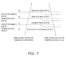
- the deodorizing operation control unit 62 performs the air supplying action such that a room humidity value detected by a room humidity sensor 90 becomes equal to or greater than a target humidity (e.g., 60%) value. Further, the deodorizing operation control unit 62 controls the various devices of the humidifying unit 50 such that the humidifying state and the ventilating state in the air supplying action switch on the basis of an outdoor air temperature value detected by an outdoor air temperature thermistor 91.
- the deodorizing operation control unit 62 performs control that stops the driving of the humidifying section 57 such that humidified air is not actively generated in the humidifying section 57 of the humidifying unit 50.
- the active generation of humidified air from the outdoor air where the humidifying rotor 51 of the humidifying section 57 is heated by the heating device 52 is not performed, and the air supplying action in the ventilating state in which the outdoor air that has been taken in from the air suction and discharge port 7c travels via the humidifying rotor 51 and the air suction and discharge switching damper 53 through the air suction and discharge hose 6 and is supplied to the indoor unit 2-that is, the ventilation air supplying action-is performed.
- the deodorizing operation control unit 62 performs control the drives that humidifying section 57 such that humidified air is actively generated in the humidifying section 57 of the humidifying unit 50.
- the deodorizing operation control unit 62 controls the various devices of the humidifying unit 50 such that the active generation of humidified air by the humidifying section 57 is not performed, and in a case where the outdoor air temperature is less than the predetermined temperature, the deodorizing operation control unit 62 controls the various devices of the humidifying unit 50 such that the active generation of humidified air by the humidifying section 57 is performed.
- the air conditioner 1 of the present embodiment assumes a hot and humid climate where, in a case where the outdoor air temperature is equal to or greater than 30°C, it is expected that there will be an absolute humidity corresponding to 60% at 30°C at a rate of occurrence of about 85%. For this reason, for example, in a case where the air conditioner 1 is applied to a climate other than a hot and humid climate, the deodorizing operation control unit performs switching between the humidifying state and the ventilating state on the basis of the room humidity value detected by the room humidity sensor, for example, and not the outdoor air temperature value.
- the deodorizing operation control unit 62 switches states between the humidifying state and the ventilating state on the basis of the outdoor temperature, but in order to improve the deodorizing effect, in the air supplying action of the deodorizing operation, the air supplying action in the humidifying state may also always be performed without the air supplying action in the ventilating state being performed.
- the judgment of the outdoor air temperature value by the deodorizing operation control unit 62 is performed every predetermined amount of time (e.g., 1 minute).
- the deodorizing operation control unit 62 causes the refrigerant to circulate in the refrigerant circuit by controlling the various devices such as the compressor 21 such that the room temperature value detected by the room temperature thermistor 92 enters a target temperature value range W.
- the target temperature value range W is a range equal to or greater than a predetermined second temperature (e.g., 20°C) value and equal to or less than the predetermined first temperature (e.g., 30°C) value.
- the predetermined first temperature and the predetermined second temperature are temperatures where the predetermined second temperature is lower than the predetermined first temperature.
- the deodorizing operation control unit 62 judges that a heating action performed at the time of the heating operation is needed and controls the various devices such that the heating action is performed.
- the heating action is one where the normal operation control unit 61 or the deodorizing operation control unit 62 switches the four-way switching valve 22 to the position of the dotted lines shown in FIG. 2 , narrows the outdoor expansion valve 25, completely opens the indoor expansion valve 17, and starts the compressor 21. For this reason, when the heating action is performed, the high-pressure refrigerant discharged from the compressor 21 condenses in the indoor heat exchanger 11, thereafter has its pressure reduced in the outdoor expansion valve 25, and flows into the outdoor heat exchanger 24.
- the deodorizing operation control unit 62 judges that a cooling action performed at the time of the cooling operation is needed and controls the various devices such that the cooling action is performed.
- the cooling action is one where the normal operation control unit 61 or the deodorizing operation control unit 62 switches the four-way switching valve 22 to the position of the solid lines shown in FIG.
- the deodorizing operation control unit 62 judges that the cooling action and the heating action are not needed, performs control that stops the driving of the various devices such as the compressor 21 and so forth in a case where the compressor 21 and so forth are being driven, and does not perform control that drives the compressor 21 and so forth in a case where the compressor 21 and so forth are not being driven.
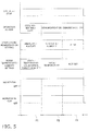
- the deodorizing operation control unit 62 judges the action at times when the room temperature rises shown in FIG. 6 .
- the deodorizing operation control unit 62 switches the three states of the ventilating and cooling state, the humidifying and heating state, and the humidifying-only state on the basis of the room temperature value and the outdoor temperature value.
- the deodorizing operation control unit 62 performs action control of the flap drive motor 9a such that the angle of inclination of the horizontal flap 9 maintains the predetermined angle at the time of the steam-out phase F1. Further, the deodorizing operation control unit 62 controls the rotation of the indoor fan 12 such that the indoor fan 12 reaches the predetermined air volume at the time of the steam-out phase F1. Moreover, the air volume adjusting unit 63 controls the rotation of the air suction and discharge fan 54 such that the air suction and discharge fan 54 reaches the air volume at the time of the steam-out phase F1.
- the deodorizing operation control unit 62 controls the various devices such as the compressor 21 and so forth such that a dehumidifying action in the water filter phase F2 of the deodorizing operation is performed using the room temperature value detected by the room temperature thermistor 92 at the time of the end of the steam-out phase F1 as a target temperature.
- the speed of the compressor 21 at this time is greater than the speed at the time of the normal operations or is a maximum speed.
- a normal dehumidifying action where the various devices are controlled by the deodorizing operation control unit 62 such that the first indoor heat exchanger 11 a and the second indoor heat exchanger 11b function as heat absorbers
- a reheat dehumidifying action where the various devices are controlled by the deodorizing operation control unit 62 such that the first indoor heat exchanger 11a functions as a heat radiator and the second indoor heat exchanger 11b functions as a heat absorber.
- the deodorizing operation control unit 62 performs the dehumidifying action of either the normal dehumidifying action or the reheat dehumidifying action on the basis of the room temperature value at the time of the end of the steam-out phase F1.
- the deodorizing operation control unit 62 judges that the reheat dehumidifying action is needed and performs the reheat dehumidifying action.
- the reheat dehumidifying action is a control action of the various devices where the deodorizing operation control unit 62 switches the four-way switching valve 22 to the position of the solid lines shown in FIG. 2 , completely opens the outdoor expansion valve 25, narrows the indoor expansion valve 17, and starts the compressor 21.
- the high-pressure refrigerant discharged from the compressor 21 flows into the first indoor heat exchanger 11a a via the outdoor heat exchanger 24 and the outdoor expansion valve 25, condenses in the first indoor heat exchanger 11a, and thereafter has its pressure reduced in the indoor expansion valve 17.
- the low-pressure refrigerant whose pressure has been reduced evaporates in the second indoor heat exchanger 11b and returns to the compressor 21 via the four-way switching valve 22 and the accumulator 23.
- the room air is heated because the refrigerant condenses in the first indoor heat exchanger 11a and the room air is cooled and dehumidified because the refrigerant evaporates in the second indoor heat exchanger 11b.
- the deodorizing operation control unit 62 judges that the normal dehumidifying action is needed and performs the normal dehumidifying action.
- the normal dehumidifying action here is an action that is the same as the dehumidifying action performed at the time of the dehumidifying operation and is a control action of the various devices where the deodorizing operation control unit 62 switches the four-way switching valve 22 to the position of the solid lines shown in FIG. 2 , narrows the outdoor expansion valve 25, completely opens the indoor expansion valve 17, and starts the compressor 21.
- the high-pressure refrigerant discharged from the compressor 21 condenses in the outdoor heat exchanger 24, thereafter has its pressure reduced in the outdoor expansion valve 25, and flows into the first indoor heat exchanger 11a. Then, the refrigerant evaporates in the first indoor heat exchanger 11a, evaporates in the second indoor heat exchanger 11b via the indoor expansion valve 17, and returns to the compressor 21 via the four-way switching valve 22 and the accumulator 23. At this time, the room air is cooled and dehumidified because the refrigerant evaporates in the first indoor heat exchanger 11 a and the second indoor heat exchanger 11b.
- the setting of the outdoor air temperature range in which the reheat dehumidifying can be executed is widened to an outdoor air temperature of 0°C such that the dehumidifying operation is performed even if the outdoor air temperature is low.
- the various devices are controlled such that the functions as a heat absorber or a heat radiator that the indoor heat exchangers 11a and 11b are currently functioning as are continued without thermo-off being performed by the deodorizing operation control unit 62.
- the dehumidifying action in the water filter phase F2 of the deodorizing operation is the normal dehumidifying action and the room temperature has fallen below the target temperature
- the state in which the first indoor heat exchanger 11a and the second indoor heat exchanger 11b are both functioning as heat absorbers is maintained by the deodorizing operation control unit 62.
- the dehumidifying action in the water filter phase F2 of the dehumidifying operation is the reheat dehumidifying operation and the room temperature has fallen below the target temperature
- the state in which the first indoor heat exchanger 11a is functioning as a heat radiator is maintained and the state in which the second indoor heat exchanger 11b is functioning as a heat absorber is maintained by the deodorizing operation control unit 62. That is, in the water filter phase F2 of the deodorizing operation, the various devices are not controlled by the deodorizing operation control unit 62 such that the indoor heat exchangers 11a and 11b concurrently function as heat radiators.
- action switching from the dehumidifying action to the heating action is not performed by the deodorizing operation control unit 62.
- the deodorizing operation control unit 62 performs the air supplying action in addition to the aforementioned dehumidifying action. Further, the deodorizing operation control unit 62 controls the various devices of the humidifying unit 50 such that the humidifying state and the ventilating state in the air supplying action switch on the basis of the outdoor air temperature value detected by the outdoor air temperature thermistor 91. Specifically, in a case where the outdoor temperature value is less than a predetermined fourth temperature (e.g., 24°C) value, the deodorizing operation control unit 62 performs the air supplying action in the humidifying state in which humidified air actively generated by the humidifying section 57 is supplied to the room-that is, the humidified air supplying action.
- a predetermined fourth temperature e.g. 24°C
- the deodorizing operation control unit 62 performs the air supplying action in the ventilating state in which the outdoor air from which humidified air is not actively generated by the humidifying section 57 is supplied to the room-that is, the ventilation air supplying action.
- the predetermined fourth temperature e.g. 24°C
- the dehumidifying action and the air supplying action are concurrently executed by the deodorizing operation control unit 62.
- the outdoor air including the humidified air generated by the humidifying section 57 is blown out into the indoor unit 2 from the opening in the end portion of the air suction and discharge hose 6.
- the outdoor air is blown out on the upstream side of the indoor heat exchanger 11 in terms of the airflow traveling through the indoor heat exchanger 11 because the opening in the end portion of the air suction and discharge hose 6 is disposed in the fore of the indoor heat exchanger 11.
- the outdoor air is, together with the air that has been taken in from the room, heated when it travels through the first indoor heat exchanger 11a functioning as a condenser or is cooled and dehumidified when it travels through the second indoor heat exchanger 11b functioning as an evaporator.
- the air that has traveled through the first indoor heat exchanger 11a and been heated and the dehumidified air that has traveled through the second indoor heat exchanger 11b and been dehumidified are mixed together, blown out from the indoor unit 2, and supplied to the room.
- the outdoor air that is not being actively humidified in the humidifying section 57 is blown out from the opening in the end portion of the air suction and discharge hose 6.
- the outdoor air is blown out on the upstream side of the indoor heat exchanger 11 in terms of the airflow traveling through the indoor heat exchanger 11 because the opening in the end portion of the air suction and discharge hose 6 is disposed in the fore of the indoor heat exchanger 11.
- the outdoor air is, together with the air that has been taken in from the room, cooled and dehumidified when it travels through the first indoor heat exchanger 11a and the second indoor heat exchanger 11b functioning as evaporators.
- the dehumidified air that has traveled through the first indoor heat exchanger 11 a and the second indoor heat exchanger 11b and been dehumidified is mixed together, blown out from the indoor unit 2, and supplied to the room.
- the deodorizing operation control unit 62 switches states from the humidifying state to the ventilating state in the air supplying action. Further, in the water filter phase F2, control that switches from the humidifying state to the ventilating state on the basis of the temperature of the indoor heat exchanger 11 is not performed.
- the deodorizing operation control unit 62 performs action control of the flap drive motor 9a such that the angle of inclination of the horizontal flap 9 maintains the predetermined angle at the time of the water filter phase F2. Further, in the humidity adjustment phase F3, the deodorizing operation control unit 62 controls the rotation of the indoor fan 12 such that the indoor fan 12 reaches the predetermined air volume at the time of the water filter phase F2. Moreover, in the humidity adjustment phase F3, the deodorizing operation control unit 62 performs control that stops the driving of the humidifying unit 50 such that the outdoor air is not supplied to the indoor unit 2.
- the deodorizing operation control unit 62 performs a dehumidifying action.
- the dehumidifying action in the humidity adjustment phase F3 is an action that is the same as the normal dehumidifying action in the dehumidifying operation and is an action that is the same as the normal dehumidifying action in the water filter phase F2.
- the deodorizing operation control unit 62 performs switching of the steam-out phase F1, the water filter phase F2, and the humidity adjustment phase F3 in the dehumidifying operation on the basis of an execution time of the deodorizing operation preset by the user by the remote controller 80 or the like. Specifically, the deodorizing operation control unit 62 applies the execution time of the deodorizing operation preset by the user to the expressions shown below to calculate the execution time of each phase.
- the deodorizing operation control unit 62 switches each phase on the basis of the execution time of each phase it has calculated in this way. For example, in a case where the predetermined first amount of time is 1 hour, the predetermined second amount of time is 30 minutes, and the execution time of the deodorizing operation has been set to 5 hours by the user, the deodorizing operation control unit 62 calculates the execution time of the steam-out phase F1 as 3 hours (predetermined first amount of time + ⁇ ), calculates the execution time of the water filter phase F2 as 1 hour 30 minutes ( ⁇ - second predetermined amount of time), and calculates the execution time of the humidity adjustment phase F3 as 30 minutes (predetermined second amount of time).
- the deodorizing operation control unit 62 switches phases in order of the steam-out phase F1, the water filter phase F2, and the humidity adjustment phase F3 on the basis of the execution time of each phase it has calculated. For this reason, in this case, as the deodorizing operation, the steam-out phase F1 is performed for 3 hours, thereafter the water filter phase F2 is performed for 1 hour 30 minutes, and thereafter the humidity adjustment phase F3 is performed for 30 minutes.
- the predetermined first amount of time is decided on the basis of the amount of time in which the humidity in the room can be raised to the target humidity at which there is a deodorizing effect by performing the air supplying action. Further, the predetermined second amount of time is decided on the basis of the amount of time in which the humidity in the room can be returned to a humidity that the room environment after the end of the deodorizing operation does not impart a feeling of discomfort to the user and at which the fear that mold and so forth will propagate in the room can be reduced by performing only the dehumidifying action and without performing the air supplying action.
- the deodorizing operation control unit 62 recalculates the execution time of each phase on the basis of the execution time after the change. Additionally, the deodorizing operation control unit 62 switches each phase on the basis of the recalculated execution time of each phase. In a case where there is a phase that has already been executed when the execution time has been changed by the user, the deodorizing operation control unit 62 does not perform control that switches to the phase that has already been executed.
- the deodorizing operation control unit 62 calculates the execution time of each phase such that the humidity adjustment phase F3 is reliably executed in the deodorizing operation excluding a case where a command to stop the deodorizing operation is given by the user. For this reason, for example, even in a case where a setting has been changed by the user such that the execution time of the deodorizing operation becomes shorter, the deodorizing operation control unit 62 ensures the execution time of the humidity adjustment phase F3 by shortening the execution time of the steam-out phase F1 or the water filter phase F2.
- a remote controller control unit that controls the remote controller 80 controls the remote controller 80 such that the data of the execution time set by the user are not transmitted to the control unit 60 and controls a display component of the remote controller 80 such that an error message is displayed on the display component.
- the deodorizing operation control unit 62 can calculate the execution time of each phase even in a case where data of an execution time less than the predetermined third amount of time have been transmitted from the remote controller 80. In a case where data of an execution time less than the predetermined third amount of time have been transmitted, the deodorizing operation control unit 62 adjusts the allocation of the execution time of each phase on the basis of a priority ranking of each phase.
- the priority ranking of each phase is the order of the humidity adjustment phase F3, the steam-out phase F1, and the water filter phase F2.
- the deodorizing operation is an operation performed in a case where a command to start the deodorizing operation from the user via the remote controller 80 or the like has been given.
- the deodorizing operation in the air conditioner 1 is started as a result of the deodorizing operation control unit 62 controlling the various devices. Consequently, even in a case where the operation of the air conditioner 1 is stopped or a case where the normal operations are being performed in the air conditioner 1, the deodorizing operation is started in the air conditioner 1 when a command to start the deodorizing operation is given from the user.
- the deodorizing operation is stopped in a case where a command to stop the deodorizing operation has been given from the user via the remote controller 80 or the like, or in a case where the execution time has elapsed since the operation has been started, or in a case where a command to start another operation (e.g., the cooling operation) from the user has been given during execution of the operation.
- a command to stop the deodorizing operation from the user has been given are, for example, a case where an operation stop button disposed on the remote controller 80 has been pressed by the user and a case where an operation stop switch disposed on the indoor unit 2 has been pressed by the user.
- the case where the execution time has elapsed since the operation has been started is a case where the deodorizing operation execution time that had been set by the user before the start of the deodorizing operation has elapsed and the operation has ended nornally-that is, a case where the steam-out phase F1, the water filter phase F2, and the humidity adjustment phase F3 have been executed on the basis of the execution time of each phase.
- the deodorizing operation control unit 62 controls the various devices on the basis of various operation settings unique to the deodorizing operation that are separate from various operation settings of the normal operations (operating mode setting, set temperature, set humidity, air direction setting other than up and down/left; and right, air volume setting, ventilation setting, etc.) transmitted from the remote controller 80 by the user, so after the end of the deodorizing operation, the control unit 60 judges whether or not the various operation settings have returned to the settings before the start of the deodorizing operation, and in a case where it has judged that the various operation settings have not returned to the settings before the start of the deodorizing operation, it performs control that returns the various operation settings to the settings before the start of the deodorizing operation.
- the normal operations operating mode setting, set temperature, set humidity, air direction setting other than up and down/left; and right, air volume setting, ventilation setting, etc.
- the normal operation control unit 61 can start the normal operations in the settings before the start of the deodorizing operation.
- the fear that a feeling of discomfort will be imparted to the user can be reduced.
- the control action of the deodorizing operation control unit 62 will be described.
- the execution time of the deodorizing operation is set to 5 hours by the user, the predetermined first amount of time is 1 hour, and the predetermined second amount of time is 30 minutes will be described as an example.
- the description below is an example of the deodorizing operation in regard to a case where, other than a command to start the deodorizing operation being transmitted from the user, no other control command is transmitted-that is, a case where the execution time has elapsed since the operation has been started.
- the deodorizing operation control unit 62 starts the deodorizing operation in the air conditioner I by controlling the various devices.
- the deodorizing operation control unit 62 decides the state in the steam-out phase F1 to be any one state of the ventilating and cooling state, the humidifying-only state, and the humidifying and heating state on the basis of the room temperature value and the outdoor temperature value at the time when the command to start the deodorizing operation was given and controls the various devices so as to become the decided state.
- the steam-out phase F1 of the deodorizing operation in the air conditioner 1 is performed.
- the deodorizing operation control unit 62 switches phases from the steam-out phase F1 to the water filter phase F2. At this time, the deodorizing operation control unit 62 judges which dehumidifying action of the reheat dehumidifying action and the normal dehumidifying action to perform in the water filter phase F2 on the basis of the room temperature value at the time when 3 hours elapsed since the steam-out phase F1 was executed.
- the deodorizing operation control unit 62 judges which air supplying action of the air supplying action in the humidifying state (humidified air supplying action) and the air supplying action in the ventilating state (ventilation air supplying action) to perform in the water filter phase F2 on the basis of the outdoor air temperature value at the time when 3 hours elapsed since the steam-out phase F2 was executed. Then, the deodorizing operation control unit 62 concurrently executes the judged dehumidifying action and the judged air supplying action, whereby the water filter phase F2 of the deodorizing operation in the air conditioner 1 is performed.
- the deodorizing operation control unit 62 switches phases from the water filter phase F2 to the humidity adjustment phase F3 by stopping the air supplying action and performing the dehumidifying action. Then, when 30 minutes elapses since the phase has switched from the water filter phase F2 to the humidity adjustment phase F3, the deodorizing operation control unit 62 stops the dehumidifying action and stops the deodorizing operation in the air conditioner 1. Thus, the deodorizing operation ends.
- the deodorizing operation is performed in the air conditioner.
- the execution time of the deodorizing operation has been set to 5 hours like in the above-described example, the following effects can be expected in each phase of the deodorizing operation. Further, in a case where the execution time of the deodorizing operation has been set to more than 5 hours, there is the potential for the effects in the deodorizing operation to further improve.
- the humidity in the room is raised by the air supplying action. Further, from 1 hour to 3 hours since the steam-out phase F1 has started, odorous components permeating fabric and so forth in the room are released into the air while the room is maintained at a high humidity by the air supplying action.
- the water filter phase F2 is started after the end of the steam-out phase F1, whereby the odorous components in the room are dissolved and recovered in the dew condensation water of the indoor heat exchanger 11 and are discharged as drain by the humidifying action, and the high-humidity air is applied to the indoor heat exchanger 11 functioning as an evaporator by the air supplying action; thus, the efficiency with which the odorous components in the room is improved and the humidity in the room is raised.
- the humidity adjustment phase F3 is started after the end of the water filter phase F2, whereby the humidity in the room is lowered by the dehumidifying action even in a case where the room humidity had been high in the steam-out phase F1.
- an air purifying filter is placed between the air intake port 2a disposed in the upper portion of the indoor unit 2 and the indoor heat exchanger 11, and the air that has been taken into the indoor unit 2 from the air intake port 2a is sent to the indoor heat exchanger 11 via the air purifying filter. For this reason, in the deodorizing operation, the odorous components in the room air are recovered by the dehumidifying action of the water filter phase F2 and removal of the odorous components in the room is performed as a result of the odorous components being adsorbed in the air purifying filter.
- the present invention can improve the efficiency with which a room is deodorized by concurrently executing an air supplying action and a dehumidifying action, so application thereof to an air conditioner that performs a deodorizing operation is effective.
Landscapes
- Engineering & Computer Science (AREA)
- Chemical & Material Sciences (AREA)
- Combustion & Propulsion (AREA)
- Mechanical Engineering (AREA)
- General Engineering & Computer Science (AREA)
- Air Conditioning Control Device (AREA)
- Devices For Blowing Cold Air, Devices For Blowing Warm Air, And Means For Preventing Water Condensation In Air Conditioning Units (AREA)
- Air Filters, Heat-Exchange Apparatuses, And Housings Of Air-Conditioning Units (AREA)
- Air Humidification (AREA)
Applications Claiming Priority (2)
| Application Number | Priority Date | Filing Date | Title |
|---|---|---|---|
| JP2008231145A JP4502054B2 (ja) | 2008-09-09 | 2008-09-09 | 空気調和機 |
| PCT/JP2009/004374 WO2010029710A1 (fr) | 2008-09-09 | 2009-09-04 | Climatiseur |
Publications (1)
| Publication Number | Publication Date |
|---|---|
| EP2333444A1 true EP2333444A1 (fr) | 2011-06-15 |
Family
ID=42004974
Family Applications (1)
| Application Number | Title | Priority Date | Filing Date |
|---|---|---|---|
| EP09812859A Withdrawn EP2333444A1 (fr) | 2008-09-09 | 2009-09-04 | Climatiseur |
Country Status (4)
| Country | Link |
|---|---|
| EP (1) | EP2333444A1 (fr) |
| JP (1) | JP4502054B2 (fr) |
| CN (1) | CN102149976B (fr) |
| WO (1) | WO2010029710A1 (fr) |
Cited By (2)
| Publication number | Priority date | Publication date | Assignee | Title |
|---|---|---|---|---|
| WO2013014455A1 (fr) * | 2011-07-28 | 2013-01-31 | John Burns | Appareil de chauffage autonome |
| EP3505838A4 (fr) * | 2016-08-25 | 2019-10-23 | Mitsubishi Electric Corporation | Dispositif de climatisation, procédé de climatisation et programme |
Families Citing this family (7)
| Publication number | Priority date | Publication date | Assignee | Title |
|---|---|---|---|---|
| US9316405B2 (en) * | 2014-07-10 | 2016-04-19 | Dana Electronics Co., Ltd. | Cyclone type humidifier and wet air purifier combination device using centrifugal force |
| KR101795953B1 (ko) | 2016-07-22 | 2017-12-01 | 엘지전자 주식회사 | 공기조화기 및 그 제어방법 |
| WO2020121598A1 (fr) * | 2018-12-14 | 2020-06-18 | パナソニックIpマネジメント株式会社 | Appareil de ventilation du type à échange de chaleur, doté de fonction de déshumidification |
| JP6922954B2 (ja) * | 2019-09-02 | 2021-08-18 | ダイキン工業株式会社 | 空調システム |
| JP7078856B2 (ja) * | 2019-09-02 | 2022-06-01 | ダイキン工業株式会社 | 空調システム |
| JP7182026B1 (ja) * | 2021-08-31 | 2022-12-01 | ダイキン工業株式会社 | 加湿装置 |
| WO2023124493A1 (fr) * | 2021-12-31 | 2023-07-06 | 海信(广东)空调有限公司 | Unité extérieure |
Family Cites Families (8)
| Publication number | Priority date | Publication date | Assignee | Title |
|---|---|---|---|---|
| CN1279320C (zh) * | 2001-06-26 | 2006-10-11 | 霓佳斯株式会社 | 空气净化方法和其所采用的空气净化装置 |
| JP2004076975A (ja) * | 2002-08-12 | 2004-03-11 | Daikin Ind Ltd | 空気調和機 |
| JP2005106358A (ja) | 2003-09-30 | 2005-04-21 | Ricoh Elemex Corp | 空気清浄機 |
| JP2005125085A (ja) | 2003-09-30 | 2005-05-19 | Hikoo Miyauchi | 揮発性有機化合物の除去方法及びその装置 |
| JP2006118798A (ja) * | 2004-10-21 | 2006-05-11 | Norihiro Amo | 加除湿・消臭装置 |
| JP2006141470A (ja) * | 2004-11-16 | 2006-06-08 | Norihiro Amo | 喫煙ユニット |
| JP2006275383A (ja) * | 2005-03-29 | 2006-10-12 | Norihiro Amo | 加除湿・冷暖房システム |
| JP2007032975A (ja) * | 2005-07-28 | 2007-02-08 | Norihiro Amo | 加除湿・除菌・消臭ウォールユニット |
-
2008
- 2008-09-09 JP JP2008231145A patent/JP4502054B2/ja active Active
-
2009
- 2009-09-04 EP EP09812859A patent/EP2333444A1/fr not_active Withdrawn
- 2009-09-04 WO PCT/JP2009/004374 patent/WO2010029710A1/fr not_active Ceased
- 2009-09-04 CN CN200980135028.3A patent/CN102149976B/zh not_active Expired - Fee Related
Non-Patent Citations (1)
| Title |
|---|
| See references of WO2010029710A1 * |
Cited By (3)
| Publication number | Priority date | Publication date | Assignee | Title |
|---|---|---|---|---|
| WO2013014455A1 (fr) * | 2011-07-28 | 2013-01-31 | John Burns | Appareil de chauffage autonome |
| EP3505838A4 (fr) * | 2016-08-25 | 2019-10-23 | Mitsubishi Electric Corporation | Dispositif de climatisation, procédé de climatisation et programme |
| EP3988852A1 (fr) * | 2016-08-25 | 2022-04-27 | Mitsubishi Electric Corporation | Dispositif de climatisation, procédé de climatisation, et programme |
Also Published As
| Publication number | Publication date |
|---|---|
| JP4502054B2 (ja) | 2010-07-14 |
| CN102149976B (zh) | 2014-04-23 |
| JP2010065884A (ja) | 2010-03-25 |
| CN102149976A (zh) | 2011-08-10 |
| WO2010029710A1 (fr) | 2010-03-18 |
Similar Documents
| Publication | Publication Date | Title |
|---|---|---|
| EP2333444A1 (fr) | Climatiseur | |
| JP4835688B2 (ja) | 空気調和装置、空調システム | |
| EP2767772B1 (fr) | Dispositif de régulation d'humidité | |
| WO2020100395A1 (fr) | Climatiseur | |
| CN107428227B (zh) | 加湿装置、车辆用空调装置 | |
| WO2011004590A1 (fr) | Système de ventilation | |
| CN101842146A (zh) | 调湿装置 | |
| JP2007010216A (ja) | 換気装置 | |
| JP5983235B2 (ja) | 調湿装置 | |
| EP2693132B1 (fr) | Dispositif de ventilation à régulation d'humidité | |
| WO2007004557A1 (fr) | Dispositif de ventilation | |
| JP4525465B2 (ja) | 空調システム | |
| JP7082269B2 (ja) | 空調機 | |
| JP2010117112A (ja) | 空気調和機 | |
| CN117836570A (zh) | 空调系统 | |
| CN118235000A (zh) | 加湿装置及空调装置 | |
| JP4597942B2 (ja) | 空気調和機 | |
| JP2010139190A (ja) | 空調機の外気導入装置 | |
| JP2022021450A (ja) | 空気浄化機能付き熱交換形換気装置 | |
| JP2022021449A (ja) | 空気浄化機能付き熱交換形換気装置 | |
| CN117813468B (zh) | 空调装置 | |
| JP2008145092A (ja) | 調湿装置 | |
| JP5067349B2 (ja) | 空気調和機 | |
| JP2010144974A (ja) | 空気調和機 | |
| JP2010121792A (ja) | 空気調和機 |
Legal Events
| Date | Code | Title | Description |
|---|---|---|---|
| PUAI | Public reference made under article 153(3) epc to a published international application that has entered the european phase |
Free format text: ORIGINAL CODE: 0009012 |
|
| 17P | Request for examination filed |
Effective date: 20110316 |
|
| AK | Designated contracting states |
Kind code of ref document: A1 Designated state(s): AT BE BG CH CY CZ DE DK EE ES FI FR GB GR HR HU IE IS IT LI LT LU LV MC MK MT NL NO PL PT RO SE SI SK SM TR |
|
| AX | Request for extension of the european patent |
Extension state: AL BA RS |
|
| DAX | Request for extension of the european patent (deleted) | ||
| STAA | Information on the status of an ep patent application or granted ep patent |
Free format text: STATUS: THE APPLICATION HAS BEEN WITHDRAWN |
|
| 18W | Application withdrawn |
Effective date: 20150129 |