EP2333457A2 - Appareil de circulation d'eau associé à un système réfrigérant - Google Patents
Appareil de circulation d'eau associé à un système réfrigérant Download PDFInfo
- Publication number
- EP2333457A2 EP2333457A2 EP20100250771 EP10250771A EP2333457A2 EP 2333457 A2 EP2333457 A2 EP 2333457A2 EP 20100250771 EP20100250771 EP 20100250771 EP 10250771 A EP10250771 A EP 10250771A EP 2333457 A2 EP2333457 A2 EP 2333457A2
- Authority
- EP
- European Patent Office
- Prior art keywords
- refrigerant
- water
- heat
- exchanger
- pipe
- Prior art date
- Legal status (The legal status is an assumption and is not a legal conclusion. Google has not performed a legal analysis and makes no representation as to the accuracy of the status listed.)
- Withdrawn
Links
- 239000003507 refrigerant Substances 0.000 title claims abstract description 362
- XLYOFNOQVPJJNP-UHFFFAOYSA-N water Substances O XLYOFNOQVPJJNP-UHFFFAOYSA-N 0.000 title claims abstract description 296
- 238000010257 thawing Methods 0.000 claims description 99
- 238000010438 heat treatment Methods 0.000 claims description 96
- 238000001816 cooling Methods 0.000 claims description 56
- 230000001105 regulatory effect Effects 0.000 claims description 9
- 238000000034 method Methods 0.000 description 15
- 230000007423 decrease Effects 0.000 description 5
- 238000012986 modification Methods 0.000 description 3
- 230000004048 modification Effects 0.000 description 3
- 230000033228 biological regulation Effects 0.000 description 2
- 230000001276 controlling effect Effects 0.000 description 2
- IJGRMHOSHXDMSA-UHFFFAOYSA-N Atomic nitrogen Chemical compound N#N IJGRMHOSHXDMSA-UHFFFAOYSA-N 0.000 description 1
- 230000006866 deterioration Effects 0.000 description 1
- 229910001873 dinitrogen Inorganic materials 0.000 description 1
- 238000004851 dishwashing Methods 0.000 description 1
- 238000009434 installation Methods 0.000 description 1
- 238000005086 pumping Methods 0.000 description 1
Images


Classifications
-
- F—MECHANICAL ENGINEERING; LIGHTING; HEATING; WEAPONS; BLASTING
- F25—REFRIGERATION OR COOLING; COMBINED HEATING AND REFRIGERATION SYSTEMS; HEAT PUMP SYSTEMS; MANUFACTURE OR STORAGE OF ICE; LIQUEFACTION SOLIDIFICATION OF GASES
- F25B—REFRIGERATION MACHINES, PLANTS OR SYSTEMS; COMBINED HEATING AND REFRIGERATION SYSTEMS; HEAT PUMP SYSTEMS
- F25B13/00—Compression machines, plants or systems, with reversible cycle
-
- F—MECHANICAL ENGINEERING; LIGHTING; HEATING; WEAPONS; BLASTING
- F25—REFRIGERATION OR COOLING; COMBINED HEATING AND REFRIGERATION SYSTEMS; HEAT PUMP SYSTEMS; MANUFACTURE OR STORAGE OF ICE; LIQUEFACTION SOLIDIFICATION OF GASES
- F25B—REFRIGERATION MACHINES, PLANTS OR SYSTEMS; COMBINED HEATING AND REFRIGERATION SYSTEMS; HEAT PUMP SYSTEMS
- F25B49/00—Arrangement or mounting of control or safety devices
- F25B49/02—Arrangement or mounting of control or safety devices for compression type machines, plants or systems
-
- F—MECHANICAL ENGINEERING; LIGHTING; HEATING; WEAPONS; BLASTING
- F25—REFRIGERATION OR COOLING; COMBINED HEATING AND REFRIGERATION SYSTEMS; HEAT PUMP SYSTEMS; MANUFACTURE OR STORAGE OF ICE; LIQUEFACTION SOLIDIFICATION OF GASES
- F25B—REFRIGERATION MACHINES, PLANTS OR SYSTEMS; COMBINED HEATING AND REFRIGERATION SYSTEMS; HEAT PUMP SYSTEMS
- F25B29/00—Combined heating and refrigeration systems, e.g. operating alternately or simultaneously
- F25B29/003—Combined heating and refrigeration systems, e.g. operating alternately or simultaneously of the compression type system
-
- F—MECHANICAL ENGINEERING; LIGHTING; HEATING; WEAPONS; BLASTING
- F25—REFRIGERATION OR COOLING; COMBINED HEATING AND REFRIGERATION SYSTEMS; HEAT PUMP SYSTEMS; MANUFACTURE OR STORAGE OF ICE; LIQUEFACTION SOLIDIFICATION OF GASES
- F25B—REFRIGERATION MACHINES, PLANTS OR SYSTEMS; COMBINED HEATING AND REFRIGERATION SYSTEMS; HEAT PUMP SYSTEMS
- F25B47/00—Arrangements for preventing or removing deposits or corrosion, not provided for in another subclass
- F25B47/02—Defrosting cycles
-
- F—MECHANICAL ENGINEERING; LIGHTING; HEATING; WEAPONS; BLASTING
- F25—REFRIGERATION OR COOLING; COMBINED HEATING AND REFRIGERATION SYSTEMS; HEAT PUMP SYSTEMS; MANUFACTURE OR STORAGE OF ICE; LIQUEFACTION SOLIDIFICATION OF GASES
- F25D—REFRIGERATORS; COLD ROOMS; ICE-BOXES; COOLING OR FREEZING APPARATUS NOT OTHERWISE PROVIDED FOR
- F25D21/00—Defrosting; Preventing frosting; Removing condensed or defrost water
- F25D21/06—Removing frost
- F25D21/12—Removing frost by hot-fluid circulating system separate from the refrigerant system
-
- F—MECHANICAL ENGINEERING; LIGHTING; HEATING; WEAPONS; BLASTING
- F25—REFRIGERATION OR COOLING; COMBINED HEATING AND REFRIGERATION SYSTEMS; HEAT PUMP SYSTEMS; MANUFACTURE OR STORAGE OF ICE; LIQUEFACTION SOLIDIFICATION OF GASES
- F25B—REFRIGERATION MACHINES, PLANTS OR SYSTEMS; COMBINED HEATING AND REFRIGERATION SYSTEMS; HEAT PUMP SYSTEMS
- F25B2339/00—Details of evaporators; Details of condensers
- F25B2339/04—Details of condensers
- F25B2339/047—Water-cooled condensers
-
- F—MECHANICAL ENGINEERING; LIGHTING; HEATING; WEAPONS; BLASTING
- F25—REFRIGERATION OR COOLING; COMBINED HEATING AND REFRIGERATION SYSTEMS; HEAT PUMP SYSTEMS; MANUFACTURE OR STORAGE OF ICE; LIQUEFACTION SOLIDIFICATION OF GASES
- F25B—REFRIGERATION MACHINES, PLANTS OR SYSTEMS; COMBINED HEATING AND REFRIGERATION SYSTEMS; HEAT PUMP SYSTEMS
- F25B2400/00—General features or devices for refrigeration machines, plants or systems, combined heating and refrigeration systems or heat-pump systems, i.e. not limited to a particular subgroup of F25B
- F25B2400/06—Several compression cycles arranged in parallel
-
- F—MECHANICAL ENGINEERING; LIGHTING; HEATING; WEAPONS; BLASTING
- F25—REFRIGERATION OR COOLING; COMBINED HEATING AND REFRIGERATION SYSTEMS; HEAT PUMP SYSTEMS; MANUFACTURE OR STORAGE OF ICE; LIQUEFACTION SOLIDIFICATION OF GASES
- F25B—REFRIGERATION MACHINES, PLANTS OR SYSTEMS; COMBINED HEATING AND REFRIGERATION SYSTEMS; HEAT PUMP SYSTEMS
- F25B2600/00—Control issues
- F25B2600/13—Pump speed control
-
- Y—GENERAL TAGGING OF NEW TECHNOLOGICAL DEVELOPMENTS; GENERAL TAGGING OF CROSS-SECTIONAL TECHNOLOGIES SPANNING OVER SEVERAL SECTIONS OF THE IPC; TECHNICAL SUBJECTS COVERED BY FORMER USPC CROSS-REFERENCE ART COLLECTIONS [XRACs] AND DIGESTS
- Y02—TECHNOLOGIES OR APPLICATIONS FOR MITIGATION OR ADAPTATION AGAINST CLIMATE CHANGE
- Y02B—CLIMATE CHANGE MITIGATION TECHNOLOGIES RELATED TO BUILDINGS, e.g. HOUSING, HOUSE APPLIANCES OR RELATED END-USER APPLICATIONS
- Y02B30/00—Energy efficient heating, ventilation or air conditioning [HVAC]
- Y02B30/70—Efficient control or regulation technologies, e.g. for control of refrigerant flow, motor or heating
Definitions
- the present disclosure relates to a water circulation apparatus associated with a refrigerant system to perform a hot water supply function and a cooling/heating function.
- a water circulation apparatus associated with a refrigerant system is an apparatus in which a refrigerant cycle and a water circulation cycle are coupled.
- a refrigerant flowing into a refrigerant pipe and water flowing into a water pipe are heat-exchanged with each other to supply hot water and cool and heat an indoor room.
- Embodiments provide a water circulation apparatus associated with a refrigerant system in which operation performance can be improved and high-temperature water can be obtained.
- Embodiments also provide a water circulation apparatus associated with a refrigerant system in which an indoor room can be heated and high-temperature water can be obtained when a refrigerant system is operated in a defrosting mode.
- a water circulation apparatus associated with a refrigerant system includes: a first refrigerant system including a first compressor and a first heat-exchanger in which air is heat-exchanged with a first refrigerant, the first refrigerant system performing a refrigerant cycle in which the first refrigerant flows; a second refrigerant system including a second compressor, the second refrigerant system performing a refrigerant cycle in which a second refrigerant flows; an intermediate heat-exchanger in which the first refrigerant is heat-exchanged with the second refrigerant while the first and second refrigerant flow; and a water circulation unit in which water is heat-exchanged with the second refrigerant while the water is circulated, the water circulation unit performing a water circulation cycle, wherein the water circulation unit includes a water pipe through which the water flows, a branch pipe branched from the water pipe to pass through the intermediate heat-exchanger, and a valve disposed in the branch pipe to regulate
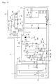
- Fig. 1 is a schematic view of a water circulation apparatus associated with a refrigerant system according to a first embodiment.
- a water circulation apparatus S associated with a refrigerant system includes a first refrigerant system 1 performing a first refrigerant cycle in which a first refrigerant is circulated, a second refrigerant system 2 in which the first refrigerant is heat-exchanged with a second refrigerant, and the second refrigerant is heat-exchanged with water, a hot water supply part 4 connected to the second refrigerant system 2 to supply hot water, and a cooling/heating part 5 connected to the second refrigerant system 2 to heat and cool an indoor room.
- the second refrigerant system 2 performs a second refrigerant cycle in which the second refrigerant is circulated.
- the first refrigerant system 1 includes a first compressor compressing the first refrigerant, a first four-way valve 12 regulating a flow direction of the first refrigerant discharged from the first compressor 11, an intermediate heat-exchanger 25 in which the first refrigerant is heat-exchanged with the second refrigerant, a first expansion part 14 expanding the first refrigerant, and a first heat-exchanger 13 in which the first refrigerant is heat-exchanged with outdoor air.
- the intermediate heat-exchanger 25 heat-exchanges the first refrigerant with the second refrigerant
- the intermediate heat-exchanger 25 may be referred to as a refrigerant-refrigerant heat-exchanger.
- the first compressor 11, the first four-way valve 12, the intermediate heat-exchanger 25, the first expansion part 14, and the first heat-exchanger 13 are connected to each other through a first refrigerant pipe 15.
- the second refrigerant system 2 includes a second compressor 21 compressing the second refrigerant, a second four-way valve 22 regulating a flow direction of the second refrigerant discharged from the second compressor 21, a second heat-exchanger 23 in which the second refrigerant is heat-exchanged with water, a second expansion part 24 expanding the second refrigerant, and the intermediate heat-exchanger 25 in which the first refrigerant is heat-exchanged with the second refrigerant.
- the second compressor 21, the second four-way valve 22, the second heat-exchanger 23, the second expansion part 24, and the intermediate heat-exchanger 25 are connected to each other through a second refrigerant pipe 26.
- the second heat-exchanger 24 since the second heat-exchanger 23 heat-exchanges the second refrigerant with the water, the second heat-exchanger 24 may be referred to as a water-refrigerant heat-exchanger.
- the intermediate heat-exchanger 25 includes a first passage 251 through which the first refrigerant flows and a second passage 252 through which the second refrigerant flows.
- the first passage 251 and the second passage 252 may be defined by the first refrigerant pipe 15 and the second refrigerant pipe 26, respectively.
- first and second passages 251 and 252 may be defined in the intermediate heat-exchanger 25.
- first refrigerant pipe 15 may be connected to the first passage 251
- second refrigerant pipe 26 may be connected to the second passage 252.
- the second heat-exchanger 23 includes a refrigerant passage 231 through which the second refrigerant flows and a water passage 232 through which the water flows.
- the refrigerant passage 231 and the water passage 232 may be defined by the second refrigerant pipe 26 and a first water pipe 30.
- a plate heat-exchanger may be used as the intermediate heat-exchanger 25 and the second heat-exchanger 23, but is not limited thereto.
- the intermediate heat-exchanger 25 may be disposed within a first case (not shown) including the first refrigerant system 1 or a second case (not shown) including the second refrigerant system 2. Also, the first refrigerant system 1 and the second refrigerant system 2 may be disposed within a single case.
- an R410a may be used as the first refrigerant
- an R134a may be used as the second refrigerant. That is, the first refrigerant of the first refrigerant system 1 is different from the second refrigerant of the second refrigerant system 2.
- the first refrigerant compressed by the first compressor 11 flows into the intermediate heat-exchanger 25 by the flow regulation of the first four-way valve 12.
- the first refrigerant flowing into the intermediate heat-exchanger 25 is heat-exchanged with the second refrigerant, and then flows into the first expansion part 14.
- the first refrigerant is expanded by the first expansion part 14 and evaporated while it flows into the first heat-exchanger 13.
- the evaporated first refrigerant is introduced into the first compressor 11. That is, when the first refrigerant system 1 is operated in the heating mode, the second refrigerant compressed by the second compressor 21 flows into the second heat-exchanger 23 by the flow regulation of the second four-way valve 22.
- the second refrigerant flowing into the second heat-exchanger 23 is heat-exchanged with the water, and then flows into the second expansion part 24. Then, the second refrigerant is expanded by the second expansion part 24 and evaporated by heat-exchanging with the first refrigerant while it flows into the intermediate heat-exchanger 25. The evaporated second refrigerant is introduced into the second compressor 21. That is, when the second refrigerant system 2 is operated in the heating mode, the intermediate heat-exchanger 25 serves as an evaporator with respect to the second refrigerant system 2.
- a solid line represents a refrigerant flow when each of the refrigerant systems is operated in a heating mode
- a dot line represents a refrigerant flow when each of the refrigerant systems is operated in a cooling mode.
- the intermediate heat exchanger 25 serves as a condenser with respect to the first refrigerant system 1 and an evaporator with respect to the second refrigerant system 2.
- the intermediate heat-exchanger 25 may serve as the evaporator with respect to each of the refrigerant systems 1 and 2.
- first refrigerant and the second refrigerant may have flow directions opposite to each other by changing the connection positions of the refrigerant pipes.
- the second refrigerant system 2 further includes a water flow device by which the water flows.
- the water flow device includes the first water pipe 30 through which the water flows, a flow switch 32 disposed in the first water flow pipe 30 to detect a water flow, an expansion tank 33 branched at a predetermined position spaced from the flow switch 32 in an water flow direction, a water collection tank 34 in which a portion of the first water pipe is inserted and including an auxiliary heater 35 therein, and a water pump 36 disposed at a predetermined position of a second water pipe 61 disposed at an outlet-side of the water collection tank 34.
- the first water pipe 30 includes an inlet pipe disposed at an inlet-side of the second heat-exchanger 23, an outlet pipe 302 disposed at an outlet-side of the second heat-exchanger 23, and a branch pipe branched from the inlet pipe 301 and joint at the outlet pipe 302.
- the outlet pipe 302 is connected to the water collection tank 34.
- a water pump 310 for pumping the water is disposed on the inlet pipe 301.
- an inverter pump that can regulate an amount of the pumped water may be used as the water pumps 36 and 310.
- the intermediate heat-exchanger 25 further includes a water passage 253 in which the water branched from the inlet pipe 301 flows. That is, the intermediate heat-exchanger 25 includes the first refrigerant passage 251, the second refrigerant passage 252, and the water passage 253.
- the first refrigerant of the first refrigerant passage 251 is heat-exchanged with the second refrigerant of the second refrigerant passage 252, and the water of the water passage 253 is heat-exchanged with the first refrigerant of the first refrigerant passage 251.
- the water of the water passage 252 may be heat may be heat-exchanged with the second refrigerant of the second refrigerant passage 252, or the water of the water passage 252 may be respectively heat-exchanged with the first refrigerant and the second refrigerant.
- the water passage 252 may be disposed such that the water and the first refrigerant may be sufficiently heat-exchanged.
- a passage extending from the inlet pipe 301 to the outlet pipe 302 via the second heat-exchanger 23 may be referred to as a main passage.
- a passage branched from the inlet pipe 301 and extending to the outlet pipe 302 via the intermediate heat-exchanger 25 may be referred to as a sub passage.
- branch pipe 303 is connected to the outlet pipe 302 in this embodiment, the branch pipe 303 may be directly connected to the water collection tank 34 without being connected to the outlet pipe 302.
- Valves 304 and 305 for regulating a flow amount of the water are disposed on inlet-side and outlet-side pipes of the intermediate heat-exchanger 25 of the branch pipe 303, respectively.
- the expansion tank 33 When the water heated while it passes through the second heat-exchanger 23 expanded to a volume greater than a reasonable volume, the expansion tank 33 performs a buffer function.
- a diaphragm (not shown) is disposed within the expansion tank 33 to move corresponding to the volume variation of the water of the outlet pipe 302.
- a nitrogen gas is filled into the expansion tank 33.
- the water collection tank 34 stores the water supplied from the outlet pipe 302.
- the auxiliary heater 35 operated when the water has a temperature less than a required temperature is disposed within the water collection tank 34.
- An air vent 343 for exhausting heated air existing within the water collection tank 34 is disposed in the water collection tank 34.
- a pressure gauge 341 and a valve 342 for regulating a pressure within the water collection tank 35 are disposed in the water collection tank 34. For example, when the pressure within the water collection tank 35 detected by the pressure gauge 341 is excessively high, the valve 342 may be opened to decrease the pressure within the water collection tank 34.
- the water pump 36 pumps the water of the water collection tank 34 to flow into the second water pipe 61.
- the water pumped into the second water pipe 61 may be supplied to the hot water supply part 4 or the cooling/heating part 5.
- the hot water supply part 4 heats and supplies water required for wash up of a user or dish-washing.
- a three-way valve 71 for regulating a flow direction of the water of the second water pipe 61 is disposed in the second water pipe 61.
- the water pumped by the water pump 36 flows into the hot water supply part 4 and/or the cooling/heating part 5 by the three-way valve 71.
- a hot water supply pipe 62 extending to the hot water supply part 4 and a cooling/heating pipe 63 extending to the cooling/heating part 5 are connected to an outlet-side of the three-way valve 71.
- the water pumped by the water pump 36 flows into the hot water supply pipe 62 and/or the cooling/heating pipe 63 under the control of the three-way valve 71.
- the hot water supply part 4 includes a hot water supply tank 41 storing water supplied from the outside and heating the stored water and an auxiliary heater 42 disposed within the hot water supply tank 41. Also, an auxiliary heat source supplying heat to the hot water supply tank 41 may be further disposed according to an installation configuration. A thermal storage tank using solar heat may be used as an available auxiliary heater.
- the hot water supply tank 41 includes a water inflow part 411 through which water is introduced and a water discharge part 412 through which heated water is discharged.
- a portion of the hot water supply pipe 62 extending from the three-way valve 71 is inserted into the hot water supply tank 41 to heat the water stored in the hot water supply tank 41. That is, heat is transmitted from the hot water flowing into the hot water supply pipe 62 to the water stored in the hot water supply tank 41.
- the auxiliary heater 42 and the auxiliary heat source may be operated to additionally supply heat to the water stored in the hot water supply tank 41.
- the auxiliary heater 42 or the auxiliary heat source may be operated.
- a temperature sensor 414 for detecting a water temperature may be disposed at a side of the hot water supply tank 41.
- hot water discharge device such as a shower 45 or an electric device such as a humidifier may be connected to the water discharge part 412.
- a thermal storage pipe 47 extending from the thermal storage tank 43 may be inserted into the hot water supply tank 41.
- An auxiliary pump 44 for controlling a flow velocity within a thermal storage pipe close loop may be disposed on the thermal storage pipe 47.
- a solenoid valve VA for controlling a flow direction of the water within the thermal storage pipe 47 may be disposed on the thermal storage pipe 47.
- a temperature sensor 471 for measuring a water temperature may be disposed at a side of the thermal storage pipe 47.
- a structure of the auxiliary heat source such as a thermal storage part using the solar heat is not limited to the proposed embodiment.
- the auxiliary heat source may have various configurations and be disposed at various positions.
- the cooling/heating part 5 includes a floor cooling/heating unit 51 in which a portion of the cooling/heating pipe 63 is buried in an indoor floor and an air cooling/heating unit 52 branched from any position of the cooling/heating pipe 63 and connected to the floor cooling/heating unit 51 in parallel.
- the floor cooling/heating unit 51 may be buried in the indoor floor in a meander line type.
- the air cooling/heating unit 52 may include a fan coil unit or a radiator.
- a portion of the air cooling/heating pipe 54 branched from the cooling/heating pipe 63 is provided in the air cooling/heating unit 52 as a heat-exchanging unit.
- Flow switching valves 55 and 56 such as the three-way valve may be disposed at a position at which the air cooling/heating pipe 54 is branched.
- water flowing along the cooling/heating pipe 63 may be divided into the floor cooling/heating unit 51 and the air cooling/heating unit 52 or flow in one direction.
- the hot water supply pipe 62 passing through the hot water supply tank 41 and the cooling/heating pipe 63 passing through the cooling/heating part 5 are connected to the inlet pipe 301.
- a check valve V for preventing the water within any one of the hot water supply pipe 62 and the cooling/heating pipe 63 from reversely flowing may be disposed in each of the hot water supply pipe 62 and the cooling/heating pipe 63.
- the water flow device disposed in the second refrigerant system 2, the hot water supply part 4, and the cooling/heating part 5 form a water circulation cycle in which water is circulated
- the above-described components may be referred to as a water circulation unit.
- the operation mode of the respective refrigerant systems includes the cooling mode, the heating mode, and the defrosting mode.
- the hot water supply part performs a hot water supply mode
- the cooling/heating part performs the cooling mode and the heating mode.
- the respective refrigerant systems are operated in the heating mode.
- the intermediate heat-exchanger 25 serves as a condenser with respect to the first refrigerant system 1 and an evaporator with respect to the second refrigerant system 2.
- the second refrigerant flowing into the intermediate heat-exchanger 25 receives heat from the first refrigerant, and then, the second refrigerant increases in temperature.
- the second refrigerant introduced into the second compressor 21 increases in temperature.
- the second refrigerant introduced into the second compressor 21 increases in temperature
- the second refrigerant discharged from the second compressed 21 increases in temperature.
- the refrigerant flowing into the second heat-exchanger 23 increases in temperature.
- a condensing temperature of the second refrigerant (or an outlet-side temperature of the second compressor 2) is higher than that (or an outlet-side temperature of the first compressor) of the first refrigerant.
- the temperature increase of the water heat-exchanged in the second heat-exchanger 23 represents that the temperature of the water stored in the water collection tank 34 increases than the water temperature of the existing system. Thus, water having a relatively higher temperature may be obtained, and the indoor room may be heated using the water having the relatively higher temperature.
- the water having the relatively higher temperature may be obtained.
- the cooling/heating system may be stably operated to obtain the water having a high temperature even through a temperature of the indoor room is very low.
- water flows into the hot water supply pipe 62 by the three-way valve 71.
- the water flows along the close loop in which the second heat-exchanger 23, the water collection tank 34, the water pump 36, the three-way valve 71, and the hot water supply pipe 62 are connected to each other.
- the water introduced through the water inflow part 411 of the hot water supply tank 41 is heated, and then discharged through the water discharge part 412, thereby supplying the water to the user.
- the hot water supply mode and the heating mode of the cooling/heating part may be selected at the same time.
- the water flows into the hot water supply pipe 62 and the cooling/heating pipe 63 by the three-way valve 71.
- the first heat-exchanger 13 of the first refrigerant system 1 serves as an evaporator.
- frost may be generated on the first heat-exchanger 13. Therefore, the defrosting process is required.
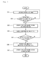
- Fig. 2 is a flowchart illustrating a defrosting operation method of a water circulation apparatus associated with a refrigerant system according to a first embodiment.
- the water circulation apparatus S associated with the refrigerant system is operated in a mode set by the user in operation S1. Since the defrosting operation of the first heat-exchanger 13 is mainly concerned in this embodiment, a case in which the respective refrigerant systems 1 and 2 are operated in the heating mode will be described.
- the branch valves 304 and 305 of the branch pipe 303 are opened.
- a portion of water flowing into the inlet pipe 301 flows into the second heat-exchanger 23, and the other portion of the water flows into the branch pipe 303.
- the water flowing from the inlet pipe 301 to the second heat-exchanger 25 is heat-exchanged with the second refrigerant, and the water branched by the branch pipe 303 is heat-exchanged with the first refrigerant in the intermediate heat-exchanger 25.
- a temperature of the water heat-exchanged with the second refrigerant is greater than that of the water heat-exchanged with the first refrigerant.
- a defrosting operation condition is satisfied during the preset mode of the water circulation apparatus S. For example, whether the defrosting operation condition is satisfied may be determined by comparing a temperature of a pipe outlet-side of the first heat-exchanger 13 to a temperature of the indoor room. However, in this embodiment, whether the defrosting operation condition may be satisfied may be determined through various methods, and this embodiment is not limited thereto.
- the first refrigerant system 1 is operated in the defrosting mode in operation S3
- the second refrigerant system 2 is maintained in the present operation mode (the heating mode).
- the water circulation apparatus is operated in the defrosting mode when the first refrigerant system is operated in the defrosting mode regardless of the operation mode of the second refrigerant system.
- a state in which the first refrigerant system 1 is operated in the defrosting mode represents a state in which the first refrigerant system 1 is operated in the cooling mode.
- the intermediate heat-exchanger 25 serves as an evaporator with respect to the respective refrigerant systems 1 and 2
- the first heat-exchanger serves as a condenser with respect to the respective refrigerant systems 1 and 2.
- the defrosting operation of the first heat-exchanger 13 is performed by the high temperature refrigerant flowing into the first heat-exchanger 13.
- the branch valves 304 and 305 are closed in operation S4.
- the water does not flow into the branch pipe 303, and the first refrigerant is heat-exchanged with the hot water within the branch pipe 303. Since the first refrigerant heat-exchanged with the hot water is heat-exchanged with the second refrigerant, each of the refrigerants may increase in temperature to minimize the reduction of the vapor pressures of the respective refrigerant systems 1 and 2.
- operation S5 it is determined whether the defrosting operation is finished during the defrosting mode of the first refrigerant system 1.
- the closed branch valves 304 and 305 are opened in operation S6.
- operation S7 the first refrigerant system 1 is operated in the previous mode. As a result, in this embodiment, the first refrigerant system 1 is operated in the heating mode.
- the hot water may be obtained, and the indoor room may be heated using the hot water.
- the hot water is heat-exchanged with the first refrigerant flowing into the intermediate heat-exchanger 25 to increase a temperature of the first refrigerant
- the reduction of the vapor pressures of the respective refrigerant systems may be minimized.
- the performance deterioration of the respective refrigerant systems may be minimized.
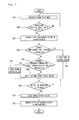
- Fig. 3 is a flowchart illustrating a defrosting operation method of a water circulation apparatus associated with a refrigerant system according to a second embodiment.
- This embodiment is equal to the first embodiment except an operation of a branch valve. Thus, only specific portions of this embodiment will be described below, and the same elements as those of the first embodiment will be revisited by referring to the same reference numbers of the corresponding elements.
- a water circulation apparatus associated with a refrigerant system is operated in a mode set by a selection of a user in operation S11. Since a defrosting operation of a first heat-exchanger 13 is mainly concerned in this embodiment, a case in which respective refrigerant systems 1 and 2 are operated in a heating mode will be described.
- branch valves 304 and 305 of a branch pipe 303 are closed.
- operation S12 it is determined whether a defrosting operation condition is satisfied when the water circulation apparatus S is operated in the set mode.
- an intermediate heat-exchanger 25 serves as an evaporator with respect to the respective refrigerant systems 1 and 2
- the first heat-exchanger serves as a condenser with respect to the respective refrigerant systems 1 and 2.
- the branch valves 304 and 305 When the branch valves 304 and 305 are opened, a portion of the water of the inlet pipe 301 flows into the intermediate heat-exchanger 25, and thus, the hot water is heat-exchanged with the first refrigerant. Then, the first refrigerant heat-exchanged with the hot water is heat-exchanged with the second refrigerant to increase the temperatures of the respective refrigerants. As a result, the reduction of vapor pressures of the respective refrigerant systems 1 and 2 may be minimized.
- operation S15 it is determined whether the defrosting operation is finished during the defrosting mode of the first refrigerant system 1.
- the branch valves 304 and 305 are closed in operation S16. Also, in operation S17, the first refrigerant system 1 is operated in the previous mode. In this embodiment, the first refrigerant system 1 will be operated in the heating mode.
- the branch valves 304 and 305 are opened. Also, when the defrosting operation is finished, the branch valves 304 and 305 may be closed.
- the branch valves 304 and 305 when the branch valves 304 and 305 are in the opened state, the branch valves 304 and 305 may be maintained in the opened state during the defrosting mode operation of the first refrigerant system 1.
- Fig. 4 is a flowchart illustrating a defrosting operation method of a water circulation apparatus associated with a refrigerant system according to a third embodiment.
- This embodiment is equal to the previously described embodiments except that a second refrigerant system is operated also in a defrosting mode when a first refrigerant system is operated in the defrosting mode.
- a second refrigerant system is operated also in a defrosting mode when a first refrigerant system is operated in the defrosting mode.
- a water circulation apparatus S associated with a refrigerant system is operated in a mode set by a selection of a user in operation S21. Since a defrosting operation of a first heat-exchanger 13 is mainly concerned in this embodiment, a case in which respective refrigerant systems 1 and 2 are operated in a heating mode will be described.
- operation S22 it is determined whether a defrosting operation condition is satisfied when the water circulation apparatus S is operated in the set mode.
- the defrosting mode operation of the first refrigerant system 1 represents a cooling mode operation of the first refrigerant system 1.
- the defrosting mode operation of the second refrigerant system 2 represents the following two cases. Firstly, the operation of the second refrigerant system 2 is stopped. Secondly, the second refrigerant system is fundamentally operated in the heating mode, and also, a second compressor 21 is operated at a frequency (e.g., a minimum frequency) lower than an operation frequency thereof in the previous mode (the heating mode).
- a frequency e.g., a minimum frequency
- the branch valves 304 and 305 may be in a closed or opened state.
- the opening or closing of the branch valves 304 and 305 when the respective refrigerant systems 1 and 2 are operated in the defrosting mode may be adjusted by the methods described in the previous embodiments.
- operation S24 it is determined whether the defrosting operation is finished during the defrosting operation of each of the respective refrigerant systems 1 and 2.
- the respective refrigerant systems 1 and 2 are operated in the previous mode in Operation S25.
- the respective refrigerant systems 1 and 2 will be operated in the heating mode.
- Fig. 5 is a flowchart illustrating a defrosting operation method of a water circulation apparatus associated with a refrigerant system according to a fourth embodiment.
- This embodiment is equal to the first and second embodiments except that an amount of water flowing into a second water pipe decreases when a first refrigerant system 1 is operated in a defrosting mode. Thus, only specific portions of this embodiment will be described below.
- a water circulation apparatus S associated with a refrigerant system is operated in a mode set by a selection of a user in operation S31. Since a defrosting operation of a first heat-exchanger 13 is mainly concerned in this embodiment, a case in which respective refrigerant systems 1 and 2 are operated in a heating mode will be described.
- operation S32 it is determined whether a defrosting operation condition is satisfied when the water circulation apparatus S is operated in the set mode.
- an intermediate heat-exchanger 25 serves as an evaporator with respect to the respective refrigerant systems 1 and 2.
- the intermediate heat-exchanger 25 serves as the evaporator with respect to the respective refrigerant systems 1 and 2
- vapor pressures of the respective refrigerant systems 1 and 2 are reduced as described above.
- a condensing temperature of a second refrigerant is reduced in the second heat-exchanger 23.
- water stored in a water collection tank 34 decreases in temperature.
- water flowing into a cooling/heating pipe 63 of a cooling/heating part 5 may decrease in temperature to lower a temperature of an indoor room.
- an operation of a water pump 36 is changed such that an amount of water pumped into a second water pipe 61 is reduced when compared that the first refrigerant system 1 is operated in the heating mode S34.
- an amount of water flowing into the cooling/heating pipe 63 of the cooling/heating part 5 may be reduced to minimize the temperature reduction of the indoor room.
- operation S35 it is determined whether the defrosting operation is finished during the defrosting mode operation of the first refrigerant system 1.
- the water pump 36 When the defrosting operation is finished, the water pump 36 is operated in the previous state. Thus, the amount of the water flowing into the second water pipe 61 is recovered to the previous state in operation S36. Also, in operation S37, the first refrigerant system 1 is operated in the previous mode.
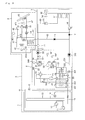
- Fig. 6 is a schematic view of a water circulation apparatus associated with a refrigerant system according to a fifth embodiment.
- This embodiment is equal to the first embodiment except a structure of an intermediate heat-exchanger and a structure in which a bypass pipe is disposed in each of respective refrigerant pipes.
- an intermediate heat-exchanger 27 includes a first refrigerant passage 271 through which a first refrigerant flows and a second refrigerant passage 272 through which a second refrigerant flows.
- a first bypass pipe 16 for bypassing the first refrigerant discharged from a first compressor 11 and having a high temperature is connected to an outlet-side pipe 151 of the first compressor 1 and an inlet-side pipe 152 of the first refrigerant passage 271 of the intermediate heat-exchanger 27.
- the first bypass pipe 16 includes a first bypass valve 17 for regulating a flow amount of the first refrigerant.
- a second bypass pipe 28 for bypassing the second refrigerant discharged from a second compressor 21 and having a high temperature is connected to an outlet-side pipe 261 of the second compressor 21 and an inlet-side pipe 262 of the second refrigerant passage 272 of the intermediate heat-exchanger 27.
- the second bypass pipe 28 includes a second bypass valve 29 for regulating a flow amount of the second refrigerant.
- the respective bypass valves 17 and 29 may be opened when the first refrigerant system 1 is operated in a defrosting mode.
- a solid line represents a refrigerant flow when each of the refrigerant systems is operated in a heating mode
- a dot line represents a refrigerant flow when each of the refrigerant systems is operated in a cooling mode.
- a chain line represents a refrigerant flow when each of the refrigerant systems is operated in the defrosting mode.
- Fig. 7 is a flowchart illustrating a defrosting operation method of a water circulation apparatus associated with a refrigerant system according to a fifth embodiment.
- a water circulation apparatus S associated with a refrigerant system is operated in a mode set by a selection of a user in operation S41. Since a defrosting operation of a first heat-exchanger 13 is mainly concerned in this embodiment, a case in which respective refrigerant systems 1 and 2 are operated in a heating mode will be described.
- operation S42 it is determined whether a defrosting operation condition is satisfied when the water circulation apparatus S is operated in the set mode.
- an intermediate heat-exchanger 27 serves as an evaporator with respect to the respective refrigerant systems 1 and 2
- the first heat-exchanger 13 serves as a condenser with respect to the respective refrigerant systems 1 and 2.
- the defrosting operation of the first heat-exchange 13 is performed by a high-temperature refrigerant flowing into the first heat-exchanger 13.
- the intermediate heat-exchanger 27 serves as the evaporator with respect to the respective refrigerant systems 1 and 2
- vapor pressures of the respective refrigerant systems 1 and 2 may be reduced to deteriorate cycle performance of each of the refrigerant systems 1 and 2 or damage the respective compressor.
- one of the bypass valves 17 and 29 is opened according to an indoor temperature.
- an indoor temperature detected by an indoor temperature sensor (not shown) exceeds a first reference temperature.
- the first reference temperature may be about 5°C.
- the first bypass valve 17 is operated to allow the first refrigerant having a high temperature to flow into the first bypass pipe 16 in operation S45.
- the indoor temperature does not exceed the first reference temperature, it is determined whether the next detected indoor temperature is between a second reference temperature lower than the first reference temperature and the first reference temperature in operation S46.
- the second reference temperature may be about -5°C.
- the second bypass valve 29 is operated to allow the second reference having a high temperature to flow into the second bypass pipe 28 in operation S47.
- the first and second bypass valves 17 and 29 are operated to allow the first refrigerant having the high temperature to flow into the first bypass pipe 16 and the second refrigerant having the high temperature to flow into the second bypass pipe 28 in operation S48.
- the high temperature refrigerant When the high temperature refrigerant is bypassed into one or more pipes of the bypass pipes 16 and 28, since the first refrigerant and/or the second refrigerant increase in temperature, it may prevent the vapor pressures of the respective refrigerant systems 1 and 2 from being reduced.
- operation S49 it is determined whether the defrosting operation is finished during the defrosting operation mode of the first refrigerant system 1.
- the opened bypass valve is closed in operation S50. Also, in operation S51, the first refrigerant system 1 is operated in the previous mode. In this embodiment, the first refrigerant system 1 will be operated in the heating mode.
- the second refrigerant system 2 may be operated in the defrosting mode or an amount of the water flowing into the cooling/heating pipe 63 may be reduced.
- the first bypass valve 17 is always operated to allow the first refrigerant to flow into the first bypass pipe 16.
- Fig. 8 is a schematic view of a water circulation apparatus associated with a refrigerant system according to a sixth embodiment.
- a water circulation apparatus S may further include the bypass pipes 16 and 28 and the bypass valves 17 and 29 of the fifth embodiment except the elements of the water circulation apparatus of the first embodiment.
- the second refrigerant heat-exchanged with the first refrigerant of the first refrigerant system is heat-exchanged with water, high temperature water may be obtained.
- the refrigerant systems may be stably operated and the high temperature water may be obtained.
- the second refrigerant system since the second refrigerant system is operated in the heating mode during the defrosting mode operation of the first refrigerant system, the high temperature water may be obtained and the indoor room may be heated using the high temperature water.
- the refrigerants may increase in temperature to minimize the reduction of the vapor pressures of the respective refrigerant systems.
Landscapes
- Engineering & Computer Science (AREA)
- Physics & Mathematics (AREA)
- Mechanical Engineering (AREA)
- Thermal Sciences (AREA)
- General Engineering & Computer Science (AREA)
- Chemical & Material Sciences (AREA)
- Combustion & Propulsion (AREA)
- Air Conditioning Control Device (AREA)
- Compression-Type Refrigeration Machines With Reversible Cycles (AREA)
- Sorption Type Refrigeration Machines (AREA)
- Other Air-Conditioning Systems (AREA)
- Heat-Pump Type And Storage Water Heaters (AREA)
Applications Claiming Priority (1)
| Application Number | Priority Date | Filing Date | Title |
|---|---|---|---|
| KR1020090123571A KR101264471B1 (ko) | 2009-12-11 | 2009-12-11 | 냉매 시스템 연동 물 순환 시스템 |
Publications (2)
| Publication Number | Publication Date |
|---|---|
| EP2333457A2 true EP2333457A2 (fr) | 2011-06-15 |
| EP2333457A3 EP2333457A3 (fr) | 2015-06-24 |
Family
ID=43920694
Family Applications (1)
| Application Number | Title | Priority Date | Filing Date |
|---|---|---|---|
| EP10250771.2A Withdrawn EP2333457A3 (fr) | 2009-12-11 | 2010-04-14 | Appareil de circulation d'eau associé à un système réfrigérant |
Country Status (4)
| Country | Link |
|---|---|
| US (1) | US20110138839A1 (fr) |
| EP (1) | EP2333457A3 (fr) |
| KR (1) | KR101264471B1 (fr) |
| CN (1) | CN102095279B (fr) |
Cited By (3)
| Publication number | Priority date | Publication date | Assignee | Title |
|---|---|---|---|---|
| EP2725310A1 (fr) * | 2012-10-29 | 2014-04-30 | Samsung Electronics Co., Ltd | Appareil de pompe à chaleur |
| WO2015030597A1 (fr) * | 2013-08-27 | 2015-03-05 | Langåker John Magne | Pompe à chaleur multifonctionnelle |
| CN115711511A (zh) * | 2022-11-11 | 2023-02-24 | 珠海格力电器股份有限公司 | 一种热氟化霜控制方法、装置和制冷设备 |
Families Citing this family (10)
| Publication number | Priority date | Publication date | Assignee | Title |
|---|---|---|---|---|
| KR101852374B1 (ko) * | 2012-01-20 | 2018-04-26 | 엘지전자 주식회사 | 실외 열교환기 |
| WO2013111177A1 (fr) * | 2012-01-24 | 2013-08-01 | 三菱電機株式会社 | Unité de climatisation |
| CN102778078A (zh) * | 2012-02-02 | 2012-11-14 | 苟仲武 | 综合制热制冷节能装置和系统 |
| CN104422196B (zh) * | 2013-09-11 | 2016-08-17 | 珠海格力电器股份有限公司 | 空调热水系统 |
| US9920997B2 (en) * | 2014-03-25 | 2018-03-20 | Samsung Electronics Co., Ltd. | Cooling apparatus and system including the same |
| WO2017141149A1 (fr) * | 2016-02-16 | 2017-08-24 | Sabic Global Technologies B.V. | Procédés et systèmes de refroidissement d'eau d'installation de traitement |
| CN108019973A (zh) * | 2017-12-28 | 2018-05-11 | 天津商业大学 | 一种新型相变蓄热制冷供热系统 |
| CN108050607A (zh) * | 2018-01-11 | 2018-05-18 | 山东荣安电子科技有限公司 | 移动式冷热一体设备 |
| US11754316B2 (en) | 2021-04-26 | 2023-09-12 | Villara Corporation | Providing domestic hot water from conventional residential split system heat pumps |
| KR20250049784A (ko) * | 2023-10-05 | 2025-04-14 | 엘지전자 주식회사 | 2단 압축 히트펌프 장치 및 그 제상 운전 방법 |
Family Cites Families (17)
| Publication number | Priority date | Publication date | Assignee | Title |
|---|---|---|---|---|
| US3392541A (en) * | 1967-02-06 | 1968-07-16 | Larkin Coils Inc | Plural compressor reverse cycle refrigeration or heat pump system |
| SE394741B (sv) * | 1974-04-18 | 1977-07-04 | Projectus Ind Produkter Ab | Vermepumpsystem |
| FR2548769B1 (fr) * | 1983-07-04 | 1986-02-21 | Satam Brandt Froid | Installation de chauffage a pompes a chaleur et a capteurs d'energie atmospherique |
| US4796437A (en) * | 1987-10-23 | 1989-01-10 | James Larry S | Multifluid heat pump system |
| JP3925383B2 (ja) | 2002-10-11 | 2007-06-06 | ダイキン工業株式会社 | 給湯装置、空調給湯システム、及び給湯システム |
| JP2004218943A (ja) | 2003-01-15 | 2004-08-05 | Matsushita Electric Ind Co Ltd | 冷暖房給湯装置 |
| JP4556453B2 (ja) | 2004-03-15 | 2010-10-06 | 株式会社富士通ゼネラル | ヒートポンプ給湯エアコン |
| KR100580277B1 (ko) * | 2004-06-16 | 2006-05-16 | 윤명혁 | 냉난방 겸용 냉온수 히트펌프 시스템 |
| KR100757941B1 (ko) | 2006-11-02 | 2007-09-12 | 삼성전자주식회사 | 공기조화기 |
| CN200972282Y (zh) * | 2006-11-15 | 2007-11-07 | 钟雪莲 | 二级压缩空气热泵热水机组 |
| CN101210748A (zh) * | 2006-12-28 | 2008-07-02 | 苏宇贵 | 空调热水复合机 |
| JP5197576B2 (ja) * | 2007-03-27 | 2013-05-15 | 三菱電機株式会社 | ヒートポンプ装置 |
| KR100835122B1 (ko) * | 2007-05-04 | 2008-06-04 | 유한회사 지오선 | 냉·난방 효율이 향상된 복합형 히트펌프 사이클 |
| CN101270938B (zh) * | 2008-05-16 | 2012-06-06 | 王全龄 | 三耦合复叠式空气源热泵空调 |
| WO2009148011A1 (fr) * | 2008-06-06 | 2009-12-10 | ダイキン工業株式会社 | Système d'eau chaude |
| CN101403540A (zh) * | 2008-11-18 | 2009-04-08 | 黄华 | 一种热泵式制热、制冰方法和装置 |
| CN201322469Y (zh) * | 2008-11-21 | 2009-10-07 | 王全龄 | 三耦合空气源热泵空调 |
-
2009
- 2009-12-11 KR KR1020090123571A patent/KR101264471B1/ko not_active Expired - Fee Related
-
2010
- 2010-02-25 CN CN201010125164.9A patent/CN102095279B/zh not_active Expired - Fee Related
- 2010-04-14 EP EP10250771.2A patent/EP2333457A3/fr not_active Withdrawn
- 2010-10-07 US US12/899,882 patent/US20110138839A1/en not_active Abandoned
Non-Patent Citations (1)
| Title |
|---|
| None |
Cited By (4)
| Publication number | Priority date | Publication date | Assignee | Title |
|---|---|---|---|---|
| EP2725310A1 (fr) * | 2012-10-29 | 2014-04-30 | Samsung Electronics Co., Ltd | Appareil de pompe à chaleur |
| US9528732B2 (en) | 2012-10-29 | 2016-12-27 | Samsung Electronics Co., Ltd. | Heat pump apparatus |
| WO2015030597A1 (fr) * | 2013-08-27 | 2015-03-05 | Langåker John Magne | Pompe à chaleur multifonctionnelle |
| CN115711511A (zh) * | 2022-11-11 | 2023-02-24 | 珠海格力电器股份有限公司 | 一种热氟化霜控制方法、装置和制冷设备 |
Also Published As
| Publication number | Publication date |
|---|---|
| CN102095279B (zh) | 2014-05-14 |
| KR20110066781A (ko) | 2011-06-17 |
| CN102095279A (zh) | 2011-06-15 |
| KR101264471B1 (ko) | 2013-05-14 |
| US20110138839A1 (en) | 2011-06-16 |
| EP2333457A3 (fr) | 2015-06-24 |
Similar Documents
| Publication | Publication Date | Title |
|---|---|---|
| EP2333457A2 (fr) | Appareil de circulation d'eau associé à un système réfrigérant | |
| JP5383816B2 (ja) | 空気調和装置 | |
| US9366452B2 (en) | Air-conditioning apparatus with primary and secondary heat exchange cycles | |
| KR101608538B1 (ko) | 냉매사이클 연동 물 순환 시스템 | |
| US20100051713A1 (en) | Hot water circulation system associated with heat pump and method for controlling the same | |
| KR101045435B1 (ko) | 냉매사이클 연동 물 순환 시스템 | |
| CN102365502A (zh) | 空气调节装置 | |
| KR101706865B1 (ko) | 공기조화기 | |
| JP6548742B2 (ja) | 空気調和装置 | |
| CN102753917B (zh) | 空气调节热水供给系统 | |
| US20190011157A1 (en) | Air conditioning apparatus | |
| KR102422008B1 (ko) | 하이브리드 멀티 공조 시스템 및 그의 제어 방법 | |
| KR101372146B1 (ko) | 난방능력이 향상된 멀티형 공기조화기 | |
| CN101660802B (zh) | 与热泵相关联的热水循环系统及其控制方法 | |
| KR101264472B1 (ko) | 냉매 시스템 연동 물 순환 시스템 | |
| KR100877056B1 (ko) | 하이브리드 히트펌프 시스템 | |
| KR20100116892A (ko) | 공기조화기 | |
| KR100877055B1 (ko) | 급탕기능을 갖는 하이브리드 히트펌프 시스템 | |
| KR101570534B1 (ko) | 냉매사이클 연동 물 순환 시스템 및 제어 방법 | |
| JP7097755B2 (ja) | 給湯暖房装置 | |
| KR101605909B1 (ko) | 히트펌프 연동 난방장치의 제어방법 | |
| KR101610958B1 (ko) | 냉매사이클 연동 물 순환 시스템 및 그 제어 방법 | |
| US20240027077A1 (en) | Hybrid multi-air conditioning system and method for controlling a hybrid multi-air conditioning system | |
| KR101319673B1 (ko) | 냉매사이클 연동 물 순환 시스템 | |
| KR101507438B1 (ko) | 히트 펌프 급탕기 및 그 제어 방법 |
Legal Events
| Date | Code | Title | Description |
|---|---|---|---|
| PUAI | Public reference made under article 153(3) epc to a published international application that has entered the european phase |
Free format text: ORIGINAL CODE: 0009012 |
|
| AK | Designated contracting states |
Kind code of ref document: A2 Designated state(s): AT BE BG CH CY CZ DE DK EE ES FI FR GB GR HR HU IE IS IT LI LT LU LV MC MK MT NL NO PL PT RO SE SI SK SM TR |
|
| AX | Request for extension of the european patent |
Extension state: AL BA ME RS |
|
| PUAL | Search report despatched |
Free format text: ORIGINAL CODE: 0009013 |
|
| AK | Designated contracting states |
Kind code of ref document: A3 Designated state(s): AT BE BG CH CY CZ DE DK EE ES FI FR GB GR HR HU IE IS IT LI LT LU LV MC MK MT NL NO PL PT RO SE SI SK SM TR |
|
| AX | Request for extension of the european patent |
Extension state: AL BA ME RS |
|
| RIC1 | Information provided on ipc code assigned before grant |
Ipc: F25B 47/02 20060101ALI20150515BHEP Ipc: F25B 13/00 20060101AFI20150515BHEP Ipc: F25B 29/00 20060101ALI20150515BHEP |
|
| STAA | Information on the status of an ep patent application or granted ep patent |
Free format text: STATUS: THE APPLICATION IS DEEMED TO BE WITHDRAWN |
|
| 18D | Application deemed to be withdrawn |
Effective date: 20160105 |