EP2333460B1 - Soupape champignon dotée d'un gain de surface à double flux - Google Patents
Soupape champignon dotée d'un gain de surface à double flux Download PDFInfo
- Publication number
- EP2333460B1 EP2333460B1 EP10194630.9A EP10194630A EP2333460B1 EP 2333460 B1 EP2333460 B1 EP 2333460B1 EP 10194630 A EP10194630 A EP 10194630A EP 2333460 B1 EP2333460 B1 EP 2333460B1
- Authority
- EP
- European Patent Office
- Prior art keywords
- poppet
- valve
- tip
- flow area
- outlet port
- Prior art date
- Legal status (The legal status is an assumption and is not a legal conclusion. Google has not performed a legal analysis and makes no representation as to the accuracy of the status listed.)
- Active
Links
Images
Classifications
-
- F—MECHANICAL ENGINEERING; LIGHTING; HEATING; WEAPONS; BLASTING
- F16—ENGINEERING ELEMENTS AND UNITS; GENERAL MEASURES FOR PRODUCING AND MAINTAINING EFFECTIVE FUNCTIONING OF MACHINES OR INSTALLATIONS; THERMAL INSULATION IN GENERAL
- F16K—VALVES; TAPS; COCKS; ACTUATING-FLOATS; DEVICES FOR VENTING OR AERATING
- F16K3/00—Gate valves or sliding valves, i.e. cut-off apparatus with closing members having a sliding movement along the seat for opening and closing
- F16K3/22—Gate valves or sliding valves, i.e. cut-off apparatus with closing members having a sliding movement along the seat for opening and closing with sealing faces shaped as surfaces of solids of revolution
- F16K3/24—Gate valves or sliding valves, i.e. cut-off apparatus with closing members having a sliding movement along the seat for opening and closing with sealing faces shaped as surfaces of solids of revolution with cylindrical valve members
- F16K3/26—Gate valves or sliding valves, i.e. cut-off apparatus with closing members having a sliding movement along the seat for opening and closing with sealing faces shaped as surfaces of solids of revolution with cylindrical valve members with fluid passages in the valve member
- F16K3/267—Combination of a sliding valve and a lift valve
-
- F—MECHANICAL ENGINEERING; LIGHTING; HEATING; WEAPONS; BLASTING
- F16—ENGINEERING ELEMENTS AND UNITS; GENERAL MEASURES FOR PRODUCING AND MAINTAINING EFFECTIVE FUNCTIONING OF MACHINES OR INSTALLATIONS; THERMAL INSULATION IN GENERAL
- F16K—VALVES; TAPS; COCKS; ACTUATING-FLOATS; DEVICES FOR VENTING OR AERATING
- F16K3/00—Gate valves or sliding valves, i.e. cut-off apparatus with closing members having a sliding movement along the seat for opening and closing
- F16K3/30—Details
- F16K3/32—Means for additional adjustment of the rate of flow
-
- F—MECHANICAL ENGINEERING; LIGHTING; HEATING; WEAPONS; BLASTING
- F25—REFRIGERATION OR COOLING; COMBINED HEATING AND REFRIGERATION SYSTEMS; HEAT PUMP SYSTEMS; MANUFACTURE OR STORAGE OF ICE; LIQUEFACTION SOLIDIFICATION OF GASES
- F25B—REFRIGERATION MACHINES, PLANTS OR SYSTEMS; COMBINED HEATING AND REFRIGERATION SYSTEMS; HEAT PUMP SYSTEMS
- F25B41/00—Fluid-circulation arrangements
- F25B41/20—Disposition of valves, e.g. of on-off valves or flow control valves
-
- F—MECHANICAL ENGINEERING; LIGHTING; HEATING; WEAPONS; BLASTING
- F25—REFRIGERATION OR COOLING; COMBINED HEATING AND REFRIGERATION SYSTEMS; HEAT PUMP SYSTEMS; MANUFACTURE OR STORAGE OF ICE; LIQUEFACTION SOLIDIFICATION OF GASES
- F25B—REFRIGERATION MACHINES, PLANTS OR SYSTEMS; COMBINED HEATING AND REFRIGERATION SYSTEMS; HEAT PUMP SYSTEMS
- F25B2400/00—Component parts or details not otherwise provided for in this subclass
- F25B2400/04—Refrigeration circuit bypassing means
- F25B2400/0403—Refrigeration circuit bypassing means for condensers
-
- F—MECHANICAL ENGINEERING; LIGHTING; HEATING; WEAPONS; BLASTING
- F25—REFRIGERATION OR COOLING; COMBINED HEATING AND REFRIGERATION SYSTEMS; HEAT PUMP SYSTEMS; MANUFACTURE OR STORAGE OF ICE; LIQUEFACTION SOLIDIFICATION OF GASES
- F25B—REFRIGERATION MACHINES, PLANTS OR SYSTEMS; COMBINED HEATING AND REFRIGERATION SYSTEMS; HEAT PUMP SYSTEMS
- F25B47/00—Arrangements for preventing or removing deposits or corrosion, not provided for in another subclass
- F25B47/02—Defrosting cycles
- F25B47/022—Defrosting cycles hot gas defrosting
-
- Y—GENERAL TAGGING OF NEW TECHNOLOGICAL DEVELOPMENTS; GENERAL TAGGING OF CROSS-SECTIONAL TECHNOLOGIES SPANNING OVER SEVERAL SECTIONS OF THE IPC; TECHNICAL SUBJECTS COVERED BY FORMER USPC CROSS-REFERENCE ART COLLECTIONS [XRACs] AND DIGESTS
- Y10—TECHNICAL SUBJECTS COVERED BY FORMER USPC
- Y10T—TECHNICAL SUBJECTS COVERED BY FORMER US CLASSIFICATION
- Y10T137/00—Fluid handling
- Y10T137/0318—Processes
Definitions
- the subject matter disclosed herein generally relates to refrigeration and/or cooling systems. More particularly, the subject matter disclosed herein relates to valves for refrigeration and/or cooling systems.
- HGBV Hot Gas Bypass Valve
- US 6293514 discloses a valve comprising a valve member including a portion engaged in a bore and shaped to regulate the flow of a fluid depending on the position of the valve member.
- a poppet valve comprising: a housing; an inlet port disposed in the housing; an outlet port disposed in the housing; and a poppet disposed in a cylinder of the housing between the inlet port and the outlet port including: a poppet body which blocks an incoming flow from proceeding from the inlet port to the outlet port when the valve is in a closed position; and a poppet tip disposed at a distal end of the poppet body, wherein the poppet tip includes a primary section which is substantially cylindrical and fits the cylinder, and a secondary section located at a distal end of the poppet which tapers from a cross-section matching the primary section to a smaller cross-section at a tip end, and the poppet tip further includes at least one tip opening extending substantially along a poppet axis to meter flow therethrough as the valve is moved from a closed position, wherein the at least one tip opening is a notch or a slot in an outer wall of the poppet tip and the tip opening extends to the poppet tip
- the invention provides a method of controlling a flow through the poppet valve.
- the method comprises translating the poppet disposed in the housing in a first direction along the poppet axis; extending the at least one tip opening at least partially across the inlet port via translation of the poppet; flowing a fluid from the inlet port through a first flow area defined by the portion of the at least one tip opening extending across the outlet port.
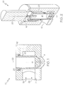
- FIG. 1 Shown in FIG. 1 is a valve 10 according to the present invention.
- the valve 10 includes an inlet port 12 and an outlet port 14 located in a valve housing 16.
- the inlet port 12 and outlet port 14 are substantially circular in cross-section, as shown in FIG. 2 , but it is to be appreciated that other cross-sectional shapes are contemplated within the scope of the present disclosure.
- the inlet port 12 and outlet port 14 are arranged perpendicular to each other.
- the poppet valve 10 includes a poppet 18 located in a cylinder 20 of the valve housing 16.
- the poppet 18 is translatable along a poppet axis 22 to regulate a flow 24 through the valve 10 via the inlet port 12 and the outlet port 14.
- the translation of the poppet 18 is powered by a stepper motor (not shown).
- a stepper motor not shown.
- at least one ring seal 26 is disposed in the valve housing 16 surrounding the poppet 18.
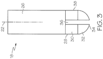
- the poppet 18 is configured to deliver two different flow area vs. valve stroke gains, and in some embodiments, both gains are linear. Referring to FIG. 3 , the configuration of the poppet 18 is shown in more detail.
- the poppet 18 includes a poppet body 26 which, in some embodiments, is cylindrical in shape and sized to fit the cylinder 20.
- the poppet body 26 extends along the poppet axis 22 to a poppet tip 28.
- the poppet tip 28 includes a primary section 30 which is substantially cylindrical and fits the cylinder 20.
- a secondary section 32 located at a distal end of the poppet 18 tapers from a cross-section matching the primary section 30 to a smaller cross-section at a tip end 34.
- the taper of the cross-section of the secondary section 32 may be curvilinear as shown or other configurations, for example, conical.
- the poppet tip 28 includes a plurality of tip openings 36. Each tip opening 36 extends along the poppet axis 22.
- the tip openings 36 shown in FIG. 3 are slots, but it is to be appreciated that other configurations, for example, notches in outer wall of the poppet tip 28, may be utilized.
- the tip openings 36 extend to the tip end 34.
- valve 10 is illustrated in a closed position.
- the poppet 18 entirely blocks an incoming flow 24 from proceeding from the inlet port 12 to the outlet port 14.
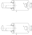
- poppet 18 translates along the poppet axis 22.
- the tip openings 36 extend from the inlet port 12 across the outlet port 14 and allow a portion of the flow 24 through the outlet port 14.
- a portion of the tip openings 36 extending from the inlet port 12 across the outlet port 14 increases, thereby increasing the portion of the flow 24 allowed through the outlet port 14.
- an increase in a flow area is linear with respect to poppet 18 movement along the poppet axis 22. Because a size of the tip openings 36 relative to the size of the outlet port 14 is small, the gain is small for this portion of the poppet 18 travel.
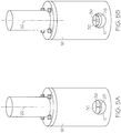
- the primary section 30 of the poppet tip 28 moves out of the outlet port 14 opening up a much larger flow area.
- the poppet 18 is shaped such that the flow area increases linearly with poppet movement 18. Since the poppet 18 movement, however, is opening a much larger flow area as shown in FIGs. 5a and 5b , the gain, or change in flow area per unit poppet 18 travel is large.
- the valve 10 provides two different flow area versus valve stroke gains which, in some embodiments are linear.
Landscapes
- Engineering & Computer Science (AREA)
- General Engineering & Computer Science (AREA)
- Mechanical Engineering (AREA)
- Physics & Mathematics (AREA)
- Thermal Sciences (AREA)
- Lift Valve (AREA)
- Fluid-Pressure Circuits (AREA)
Claims (14)
- Soupape champignon (10), comprenant :un boîtier (16) ;un orifice d'entrée (12) disposé dans le boîtier (16) ;un orifice de sortie (14) disposé dans le boîtier (16) ; etun champignon (18) disposé dans un cylindre (20) du boîtier (16) entre l'orifice d'entrée (12) et l'orifice de sortie (14), comportant :un corps champignon (26) qui empêche un flux entrant (24) de passer de l'orifice d'entrée à l'orifice de sortie (14) lorsque la soupape (10) est dans une position fermée ; etune pointe de champignon (28) disposée à une extrémité distale du corps champignon (26), dans laquelle la pointe de champignon comporte une section primaire (30) qui est sensiblement cylindrique et s'adapte au cylindre, et une section secondaire (32) située à une extrémité distale du champignon (18) qui s'effile d'une section transversale correspondant à la section primaire (30) à une section transversale plus petite au niveau d'une extrémité de pointe (34), et la pointe de champignon comporte en outre au moins une ouverture de pointe (36) s'étendant sensiblement le long d'un axe de champignon (22) pour mesurer le flux à travers celle-ci lorsque la soupape (10) est déplacée depuis une position fermée,caractérisée en ce quel'au moins une ouverture de pointe (36) est une encoche ou une fente dans une paroi extérieure (38) de la pointe de champignon (28) et l'ouverture de pointe (36) s'étend jusqu'à l'extrémité de pointe de champignon.
- Soupape champignon (10) selon la revendication 1, dans laquelle l'au moins une ouverture de pointe (36) est configurée pour modifier une surface de flux de soupape de manière linéaire lorsque le champignon (18) est translaté le long de l'axe de champignon (22).
- Soupape champignon (10) selon la revendication 1 ou 2, dans laquelle la pointe de champignon (28) comporte une extrémité de pointe effilée (34).
- Soupape champignon (10) selon la revendication 3, dans laquelle l'extrémité de pointe (34) est effilée de manière curviligne.
- Soupape champignon (10) selon la revendication 3 ou 4, dans laquelle une première surface de flux à travers l'au moins une ouverture de pointe (36) est sensiblement plus petite qu'une seconde surface de flux au-delà de l'extrémité de pointe (34).
- Soupape champignon (10) selon une quelconque revendication précédente, dans laquelle l'orifice d'entrée (12) est disposé selon un angle sensiblement égal à 90 degrés par rapport à l'orifice de sortie (14).
- Procédé de commande d'un flux à travers la soupape champignon (10) selon une quelconque revendication précédente, comprenant :la translation du champignon (18) disposé dans le boîtier (16) dans une première direction le long de l'axe de champignon (22) ;l'extension de l'au moins une ouverture de pointe (36) au moins partiellement à travers l'orifice d'entrée (12) par l'intermédiaire de la translation du champignon (18) ;l'écoulement d'un fluide depuis l'orifice d'entrée (12) à travers une première surface de flux définie par la partie de l'au moins une ouverture de pointe (36) s'étendant à travers l'orifice de sortie (14).
- Procédé selon la revendication 7, dans lequel une dimension de la première surface de flux est modifiée de manière linéaire par translation unitaire du champignon (18) le long de l'axe de champignon (22).
- Procédé selon la revendication 7 ou 8, comprenant en outre la translation du champignon (18) dans la première direction le long de l'axe de champignon (22) de sorte que l'extrémité de pointe (34) est disposée au moins partiellement à travers l'orifice de sortie (14).
- Procédé selon la revendication 9, comprenant l'écoulement du fluide à travers une seconde surface de flux définie par l'extrémité de pointe (34) et l'orifice de sortie (14) ; de préférence dans lequel la seconde surface de flux est sensiblement plus grande que la première surface de flux.
- Procédé selon la revendication 10, dans lequel une dimension de la seconde surface de flux est modifiée de manière linéaire par translation unitaire du champignon (18) le long de l'axe de champignon (22).
- Procédé selon la revendication 7, 8, 9, 10 ou 11, comprenant l'écoulement du fluide en dehors de la soupape par l'intermédiaire d'au moins un orifice de sortie.
- Procédé selon la revendication 12, dans lequel l'orifice de sortie (14) est disposé selon un angle sensiblement égal à 90 degrés depuis l'orifice d'entrée (12).
- Procédé selon l'une quelconque des revendications 7 à 13, comprenant la translation du champignon (18) dans une seconde direction sensiblement opposée à la première direction afin de réduire le flux à travers la soupape (10).
Applications Claiming Priority (1)
| Application Number | Priority Date | Filing Date | Title |
|---|---|---|---|
| US12/635,035 US8356617B2 (en) | 2009-12-10 | 2009-12-10 | Poppet valve with dual flow area gain |
Publications (3)
| Publication Number | Publication Date |
|---|---|
| EP2333460A2 EP2333460A2 (fr) | 2011-06-15 |
| EP2333460A3 EP2333460A3 (fr) | 2012-01-04 |
| EP2333460B1 true EP2333460B1 (fr) | 2019-11-20 |
Family
ID=43858410
Family Applications (1)
| Application Number | Title | Priority Date | Filing Date |
|---|---|---|---|
| EP10194630.9A Active EP2333460B1 (fr) | 2009-12-10 | 2010-12-10 | Soupape champignon dotée d'un gain de surface à double flux |
Country Status (2)
| Country | Link |
|---|---|
| US (1) | US8356617B2 (fr) |
| EP (1) | EP2333460B1 (fr) |
Families Citing this family (2)
| Publication number | Priority date | Publication date | Assignee | Title |
|---|---|---|---|---|
| ITMI20120289A1 (it) * | 2012-02-27 | 2013-08-28 | Dropsa Spa | Dispositivo di lubrificazione con regolazione della portata di lubrificante fluido |
| ITMI20120288A1 (it) | 2012-02-27 | 2013-08-28 | Dropsa Spa | Dispositivo di lubrificazione con misuratore di portata |
Family Cites Families (14)
| Publication number | Priority date | Publication date | Assignee | Title |
|---|---|---|---|---|
| US1619937A (en) * | 1925-06-15 | 1927-03-08 | Universal Oil Prod Co | Valve |
| US2014314A (en) * | 1931-07-22 | 1935-09-10 | Phillips Petroleum Co | Adjustable orifice valve |
| US2541176A (en) * | 1945-01-22 | 1951-02-13 | Mason Neilan Regulator Company | Control valve |
| US2980392A (en) * | 1957-08-27 | 1961-04-18 | Eugene C Greenwood | Combination metering and shut-off valve |
| US4015631A (en) * | 1975-03-07 | 1977-04-05 | Ewarts Limited | Gas taps |
| JPS63180783U (fr) * | 1987-05-14 | 1988-11-22 | ||
| US4793589A (en) * | 1987-06-18 | 1988-12-27 | Gilbarco Inc. | Piston valve with proportional solenoid controlled pilot valve |
| US5544856A (en) * | 1994-07-13 | 1996-08-13 | Eaton Corporation | Remotely controlling modulated flow to a fuel gas burner and valve therefor |
| FR2773865B1 (fr) * | 1998-01-21 | 2000-03-24 | Theobald A | Vanne de reglage de debit |
| US6807984B2 (en) * | 2001-12-26 | 2004-10-26 | Fsi International, Inc. | High flow high control valve and assembly |
| US6935616B2 (en) * | 2003-07-18 | 2005-08-30 | Hans D. Baumann | Balanced plug valve |
| US20070040136A1 (en) * | 2005-08-22 | 2007-02-22 | Caprera Brian J | Fluid control valve device |
| US20090057592A1 (en) * | 2007-08-28 | 2009-03-05 | Lakhan Haresh C | Flow control and closure valve with axial flow in the valve element |
| US7819134B2 (en) * | 2007-09-04 | 2010-10-26 | Masco Corporation Of Indiana | Valve fitting with integral stops |
-
2009
- 2009-12-10 US US12/635,035 patent/US8356617B2/en active Active
-
2010
- 2010-12-10 EP EP10194630.9A patent/EP2333460B1/fr active Active
Non-Patent Citations (1)
| Title |
|---|
| None * |
Also Published As
| Publication number | Publication date |
|---|---|
| US20110139254A1 (en) | 2011-06-16 |
| EP2333460A2 (fr) | 2011-06-15 |
| US8356617B2 (en) | 2013-01-22 |
| EP2333460A3 (fr) | 2012-01-04 |
Similar Documents
| Publication | Publication Date | Title |
|---|---|---|
| EP2373910B1 (fr) | Vanne de régulation de fluide | |
| EP3594543B1 (fr) | Soupape de réglage de débit à commande électrique | |
| CN102369376B (zh) | 压强无关型控制阀 | |
| EP3129660B1 (fr) | Servovalve | |
| US11236845B2 (en) | Valve trim apparatus having multiple fluid flow control members | |
| EP2333460B1 (fr) | Soupape champignon dotée d'un gain de surface à double flux | |
| CN108071818B (zh) | 四通阀 | |
| EP3212976B1 (fr) | Ensemble chapeau encastré pour soupape d'écoulement axial, et soupape d'écoulement axial le comprenant | |
| CN104137015B (zh) | 控制阀 | |
| US6926249B2 (en) | Precision modulating globe valve | |
| WO2016001475A1 (fr) | Vanne | |
| KR20170044200A (ko) | 전자기 작동식 팽창 밸브 | |
| EP3009619B1 (fr) | Actionneur de soupape d'échange gazeux pour le déplacement axial d'une soupape d'échange gazeux d'un moteur à combustion | |
| KR20150024874A (ko) | 선형 작동기를 갖는 축방향 유체 밸브 | |
| US20120085948A1 (en) | Actuator for controlling a fluid flow | |
| EP2716945A1 (fr) | Compensation de débit pour soupape | |
| US6534003B1 (en) | Valve and a method of using a valve | |
| EP4196706B1 (fr) | Bague fendue montée sur un élastomère | |
| WO2023052265A1 (fr) | Ensemble soupape | |
| US20070176135A1 (en) | Dual bushing rod seal |
Legal Events
| Date | Code | Title | Description |
|---|---|---|---|
| PUAI | Public reference made under article 153(3) epc to a published international application that has entered the european phase |
Free format text: ORIGINAL CODE: 0009012 |
|
| AK | Designated contracting states |
Kind code of ref document: A2 Designated state(s): AL AT BE BG CH CY CZ DE DK EE ES FI FR GB GR HR HU IE IS IT LI LT LU LV MC MK MT NL NO PL PT RO RS SE SI SK SM TR |
|
| AX | Request for extension of the european patent |
Extension state: BA ME |
|
| PUAL | Search report despatched |
Free format text: ORIGINAL CODE: 0009013 |
|
| AK | Designated contracting states |
Kind code of ref document: A3 Designated state(s): AL AT BE BG CH CY CZ DE DK EE ES FI FR GB GR HR HU IE IS IT LI LT LU LV MC MK MT NL NO PL PT RO RS SE SI SK SM TR |
|
| AX | Request for extension of the european patent |
Extension state: BA ME |
|
| RIC1 | Information provided on ipc code assigned before grant |
Ipc: F25B 47/02 20060101ALI20111130BHEP Ipc: F25B 41/04 20060101AFI20111130BHEP |
|
| 17P | Request for examination filed |
Effective date: 20120704 |
|
| STAA | Information on the status of an ep patent application or granted ep patent |
Free format text: STATUS: EXAMINATION IS IN PROGRESS |
|
| 17Q | First examination report despatched |
Effective date: 20170327 |
|
| GRAP | Despatch of communication of intention to grant a patent |
Free format text: ORIGINAL CODE: EPIDOSNIGR1 |
|
| STAA | Information on the status of an ep patent application or granted ep patent |
Free format text: STATUS: GRANT OF PATENT IS INTENDED |
|
| INTG | Intention to grant announced |
Effective date: 20190603 |
|
| GRAS | Grant fee paid |
Free format text: ORIGINAL CODE: EPIDOSNIGR3 |
|
| GRAA | (expected) grant |
Free format text: ORIGINAL CODE: 0009210 |
|
| STAA | Information on the status of an ep patent application or granted ep patent |
Free format text: STATUS: THE PATENT HAS BEEN GRANTED |
|
| AK | Designated contracting states |
Kind code of ref document: B1 Designated state(s): AL AT BE BG CH CY CZ DE DK EE ES FI FR GB GR HR HU IE IS IT LI LT LU LV MC MK MT NL NO PL PT RO RS SE SI SK SM TR |
|
| RAP1 | Party data changed (applicant data changed or rights of an application transferred) |
Owner name: HAMILTON SUNDSTRAND CORPORATION |
|
| REG | Reference to a national code |
Ref country code: GB Ref legal event code: FG4D |
|
| REG | Reference to a national code |
Ref country code: CH Ref legal event code: EP |
|
| REG | Reference to a national code |
Ref country code: IE Ref legal event code: FG4D |
|
| REG | Reference to a national code |
Ref country code: DE Ref legal event code: R096 Ref document number: 602010062013 Country of ref document: DE |
|
| REG | Reference to a national code |
Ref country code: AT Ref legal event code: REF Ref document number: 1204641 Country of ref document: AT Kind code of ref document: T Effective date: 20191215 |
|
| REG | Reference to a national code |
Ref country code: NL Ref legal event code: MP Effective date: 20191120 |
|
| REG | Reference to a national code |
Ref country code: LT Ref legal event code: MG4D |
|
| PG25 | Lapsed in a contracting state [announced via postgrant information from national office to epo] |
Ref country code: NO Free format text: LAPSE BECAUSE OF FAILURE TO SUBMIT A TRANSLATION OF THE DESCRIPTION OR TO PAY THE FEE WITHIN THE PRESCRIBED TIME-LIMIT Effective date: 20200220 Ref country code: BG Free format text: LAPSE BECAUSE OF FAILURE TO SUBMIT A TRANSLATION OF THE DESCRIPTION OR TO PAY THE FEE WITHIN THE PRESCRIBED TIME-LIMIT Effective date: 20200220 Ref country code: FI Free format text: LAPSE BECAUSE OF FAILURE TO SUBMIT A TRANSLATION OF THE DESCRIPTION OR TO PAY THE FEE WITHIN THE PRESCRIBED TIME-LIMIT Effective date: 20191120 Ref country code: SE Free format text: LAPSE BECAUSE OF FAILURE TO SUBMIT A TRANSLATION OF THE DESCRIPTION OR TO PAY THE FEE WITHIN THE PRESCRIBED TIME-LIMIT Effective date: 20191120 Ref country code: LV Free format text: LAPSE BECAUSE OF FAILURE TO SUBMIT A TRANSLATION OF THE DESCRIPTION OR TO PAY THE FEE WITHIN THE PRESCRIBED TIME-LIMIT Effective date: 20191120 Ref country code: LT Free format text: LAPSE BECAUSE OF FAILURE TO SUBMIT A TRANSLATION OF THE DESCRIPTION OR TO PAY THE FEE WITHIN THE PRESCRIBED TIME-LIMIT Effective date: 20191120 Ref country code: GR Free format text: LAPSE BECAUSE OF FAILURE TO SUBMIT A TRANSLATION OF THE DESCRIPTION OR TO PAY THE FEE WITHIN THE PRESCRIBED TIME-LIMIT Effective date: 20200221 Ref country code: NL Free format text: LAPSE BECAUSE OF FAILURE TO SUBMIT A TRANSLATION OF THE DESCRIPTION OR TO PAY THE FEE WITHIN THE PRESCRIBED TIME-LIMIT Effective date: 20191120 Ref country code: ES Free format text: LAPSE BECAUSE OF FAILURE TO SUBMIT A TRANSLATION OF THE DESCRIPTION OR TO PAY THE FEE WITHIN THE PRESCRIBED TIME-LIMIT Effective date: 20191120 |
|
| PG25 | Lapsed in a contracting state [announced via postgrant information from national office to epo] |
Ref country code: IS Free format text: LAPSE BECAUSE OF FAILURE TO SUBMIT A TRANSLATION OF THE DESCRIPTION OR TO PAY THE FEE WITHIN THE PRESCRIBED TIME-LIMIT Effective date: 20200320 Ref country code: RS Free format text: LAPSE BECAUSE OF FAILURE TO SUBMIT A TRANSLATION OF THE DESCRIPTION OR TO PAY THE FEE WITHIN THE PRESCRIBED TIME-LIMIT Effective date: 20191120 Ref country code: HR Free format text: LAPSE BECAUSE OF FAILURE TO SUBMIT A TRANSLATION OF THE DESCRIPTION OR TO PAY THE FEE WITHIN THE PRESCRIBED TIME-LIMIT Effective date: 20191120 |
|
| PG25 | Lapsed in a contracting state [announced via postgrant information from national office to epo] |
Ref country code: AL Free format text: LAPSE BECAUSE OF FAILURE TO SUBMIT A TRANSLATION OF THE DESCRIPTION OR TO PAY THE FEE WITHIN THE PRESCRIBED TIME-LIMIT Effective date: 20191120 |
|
| REG | Reference to a national code |
Ref country code: DE Ref legal event code: R119 Ref document number: 602010062013 Country of ref document: DE |
|
| PG25 | Lapsed in a contracting state [announced via postgrant information from national office to epo] |
Ref country code: DK Free format text: LAPSE BECAUSE OF FAILURE TO SUBMIT A TRANSLATION OF THE DESCRIPTION OR TO PAY THE FEE WITHIN THE PRESCRIBED TIME-LIMIT Effective date: 20191120 Ref country code: EE Free format text: LAPSE BECAUSE OF FAILURE TO SUBMIT A TRANSLATION OF THE DESCRIPTION OR TO PAY THE FEE WITHIN THE PRESCRIBED TIME-LIMIT Effective date: 20191120 Ref country code: PT Free format text: LAPSE BECAUSE OF FAILURE TO SUBMIT A TRANSLATION OF THE DESCRIPTION OR TO PAY THE FEE WITHIN THE PRESCRIBED TIME-LIMIT Effective date: 20200412 Ref country code: RO Free format text: LAPSE BECAUSE OF FAILURE TO SUBMIT A TRANSLATION OF THE DESCRIPTION OR TO PAY THE FEE WITHIN THE PRESCRIBED TIME-LIMIT Effective date: 20191120 Ref country code: CZ Free format text: LAPSE BECAUSE OF FAILURE TO SUBMIT A TRANSLATION OF THE DESCRIPTION OR TO PAY THE FEE WITHIN THE PRESCRIBED TIME-LIMIT Effective date: 20191120 |
|
| REG | Reference to a national code |
Ref country code: CH Ref legal event code: PL |
|
| REG | Reference to a national code |
Ref country code: AT Ref legal event code: MK05 Ref document number: 1204641 Country of ref document: AT Kind code of ref document: T Effective date: 20191120 |
|
| REG | Reference to a national code |
Ref country code: BE Ref legal event code: MM Effective date: 20191231 |
|
| PG25 | Lapsed in a contracting state [announced via postgrant information from national office to epo] |
Ref country code: SM Free format text: LAPSE BECAUSE OF FAILURE TO SUBMIT A TRANSLATION OF THE DESCRIPTION OR TO PAY THE FEE WITHIN THE PRESCRIBED TIME-LIMIT Effective date: 20191120 Ref country code: MC Free format text: LAPSE BECAUSE OF FAILURE TO SUBMIT A TRANSLATION OF THE DESCRIPTION OR TO PAY THE FEE WITHIN THE PRESCRIBED TIME-LIMIT Effective date: 20191120 Ref country code: SK Free format text: LAPSE BECAUSE OF FAILURE TO SUBMIT A TRANSLATION OF THE DESCRIPTION OR TO PAY THE FEE WITHIN THE PRESCRIBED TIME-LIMIT Effective date: 20191120 |
|
| PLBE | No opposition filed within time limit |
Free format text: ORIGINAL CODE: 0009261 |
|
| STAA | Information on the status of an ep patent application or granted ep patent |
Free format text: STATUS: NO OPPOSITION FILED WITHIN TIME LIMIT |
|
| 26N | No opposition filed |
Effective date: 20200821 |
|
| GBPC | Gb: european patent ceased through non-payment of renewal fee |
Effective date: 20200220 |
|
| PG25 | Lapsed in a contracting state [announced via postgrant information from national office to epo] |
Ref country code: DE Free format text: LAPSE BECAUSE OF NON-PAYMENT OF DUE FEES Effective date: 20200701 Ref country code: IE Free format text: LAPSE BECAUSE OF NON-PAYMENT OF DUE FEES Effective date: 20191210 Ref country code: LU Free format text: LAPSE BECAUSE OF NON-PAYMENT OF DUE FEES Effective date: 20191210 |
|
| PG25 | Lapsed in a contracting state [announced via postgrant information from national office to epo] |
Ref country code: CH Free format text: LAPSE BECAUSE OF NON-PAYMENT OF DUE FEES Effective date: 20191231 Ref country code: LI Free format text: LAPSE BECAUSE OF NON-PAYMENT OF DUE FEES Effective date: 20191231 Ref country code: AT Free format text: LAPSE BECAUSE OF FAILURE TO SUBMIT A TRANSLATION OF THE DESCRIPTION OR TO PAY THE FEE WITHIN THE PRESCRIBED TIME-LIMIT Effective date: 20191120 Ref country code: SI Free format text: LAPSE BECAUSE OF FAILURE TO SUBMIT A TRANSLATION OF THE DESCRIPTION OR TO PAY THE FEE WITHIN THE PRESCRIBED TIME-LIMIT Effective date: 20191120 Ref country code: BE Free format text: LAPSE BECAUSE OF NON-PAYMENT OF DUE FEES Effective date: 20191231 Ref country code: PL Free format text: LAPSE BECAUSE OF FAILURE TO SUBMIT A TRANSLATION OF THE DESCRIPTION OR TO PAY THE FEE WITHIN THE PRESCRIBED TIME-LIMIT Effective date: 20191120 |
|
| PG25 | Lapsed in a contracting state [announced via postgrant information from national office to epo] |
Ref country code: GB Free format text: LAPSE BECAUSE OF NON-PAYMENT OF DUE FEES Effective date: 20200220 |
|
| PG25 | Lapsed in a contracting state [announced via postgrant information from national office to epo] |
Ref country code: CY Free format text: LAPSE BECAUSE OF FAILURE TO SUBMIT A TRANSLATION OF THE DESCRIPTION OR TO PAY THE FEE WITHIN THE PRESCRIBED TIME-LIMIT Effective date: 20191120 |
|
| PG25 | Lapsed in a contracting state [announced via postgrant information from national office to epo] |
Ref country code: MT Free format text: LAPSE BECAUSE OF FAILURE TO SUBMIT A TRANSLATION OF THE DESCRIPTION OR TO PAY THE FEE WITHIN THE PRESCRIBED TIME-LIMIT Effective date: 20191120 Ref country code: HU Free format text: LAPSE BECAUSE OF FAILURE TO SUBMIT A TRANSLATION OF THE DESCRIPTION OR TO PAY THE FEE WITHIN THE PRESCRIBED TIME-LIMIT; INVALID AB INITIO Effective date: 20101210 |
|
| PG25 | Lapsed in a contracting state [announced via postgrant information from national office to epo] |
Ref country code: TR Free format text: LAPSE BECAUSE OF FAILURE TO SUBMIT A TRANSLATION OF THE DESCRIPTION OR TO PAY THE FEE WITHIN THE PRESCRIBED TIME-LIMIT Effective date: 20191120 |
|
| PG25 | Lapsed in a contracting state [announced via postgrant information from national office to epo] |
Ref country code: MK Free format text: LAPSE BECAUSE OF FAILURE TO SUBMIT A TRANSLATION OF THE DESCRIPTION OR TO PAY THE FEE WITHIN THE PRESCRIBED TIME-LIMIT Effective date: 20191120 |
|
| P01 | Opt-out of the competence of the unified patent court (upc) registered |
Effective date: 20230522 |
|
| PGFP | Annual fee paid to national office [announced via postgrant information from national office to epo] |
Ref country code: IT Payment date: 20251119 Year of fee payment: 16 |
|
| PGFP | Annual fee paid to national office [announced via postgrant information from national office to epo] |
Ref country code: FR Payment date: 20251120 Year of fee payment: 16 |