EP2333539A1 - Colonne de chromatographe à gaz et son procédé de fabrication - Google Patents
Colonne de chromatographe à gaz et son procédé de fabrication Download PDFInfo
- Publication number
- EP2333539A1 EP2333539A1 EP10194013A EP10194013A EP2333539A1 EP 2333539 A1 EP2333539 A1 EP 2333539A1 EP 10194013 A EP10194013 A EP 10194013A EP 10194013 A EP10194013 A EP 10194013A EP 2333539 A1 EP2333539 A1 EP 2333539A1
- Authority
- EP
- European Patent Office
- Prior art keywords
- groove
- gas
- flow passage
- substrate
- gas chromatograph
- Prior art date
- Legal status (The legal status is an assumption and is not a legal conclusion. Google has not performed a legal analysis and makes no representation as to the accuracy of the status listed.)
- Withdrawn
Links
Images




Classifications
-
- G—PHYSICS
- G01—MEASURING; TESTING
- G01N—INVESTIGATING OR ANALYSING MATERIALS BY DETERMINING THEIR CHEMICAL OR PHYSICAL PROPERTIES
- G01N30/00—Investigating or analysing materials by separation into components using adsorption, absorption or similar phenomena or using ion-exchange, e.g. chromatography or field flow fractionation
- G01N30/02—Column chromatography
- G01N30/60—Construction of the column
- G01N30/6095—Micromachined or nanomachined, e.g. micro- or nanosize
-
- B—PERFORMING OPERATIONS; TRANSPORTING
- B01—PHYSICAL OR CHEMICAL PROCESSES OR APPARATUS IN GENERAL
- B01D—SEPARATION
- B01D53/00—Separation of gases or vapours; Recovering vapours of volatile solvents from gases; Chemical or biological purification of waste gases, e.g. engine exhaust gases, smoke, fumes, flue gases, aerosols
- B01D53/02—Separation of gases or vapours; Recovering vapours of volatile solvents from gases; Chemical or biological purification of waste gases, e.g. engine exhaust gases, smoke, fumes, flue gases, aerosols by adsorption, e.g. preparative gas chromatography
-
- G—PHYSICS
- G01—MEASURING; TESTING
- G01N—INVESTIGATING OR ANALYSING MATERIALS BY DETERMINING THEIR CHEMICAL OR PHYSICAL PROPERTIES
- G01N30/00—Investigating or analysing materials by separation into components using adsorption, absorption or similar phenomena or using ion-exchange, e.g. chromatography or field flow fractionation
- G01N30/02—Column chromatography
- G01N30/50—Conditioning of the sorbent material or stationary liquid
- G01N30/56—Packing methods or coating methods
-
- G—PHYSICS
- G01—MEASURING; TESTING
- G01N—INVESTIGATING OR ANALYSING MATERIALS BY DETERMINING THEIR CHEMICAL OR PHYSICAL PROPERTIES
- G01N30/00—Investigating or analysing materials by separation into components using adsorption, absorption or similar phenomena or using ion-exchange, e.g. chromatography or field flow fractionation
- G01N30/02—Column chromatography
- G01N30/60—Construction of the column
- G01N30/6052—Construction of the column body
-
- B—PERFORMING OPERATIONS; TRANSPORTING
- B01—PHYSICAL OR CHEMICAL PROCESSES OR APPARATUS IN GENERAL
- B01D—SEPARATION
- B01D2253/00—Adsorbents used in seperation treatment of gases and vapours
- B01D2253/10—Inorganic adsorbents
- B01D2253/102—Carbon
-
- B—PERFORMING OPERATIONS; TRANSPORTING
- B01—PHYSICAL OR CHEMICAL PROCESSES OR APPARATUS IN GENERAL
- B01D—SEPARATION
- B01D2253/00—Adsorbents used in seperation treatment of gases and vapours
- B01D2253/10—Inorganic adsorbents
- B01D2253/104—Alumina
-
- B—PERFORMING OPERATIONS; TRANSPORTING
- B01—PHYSICAL OR CHEMICAL PROCESSES OR APPARATUS IN GENERAL
- B01D—SEPARATION
- B01D2253/00—Adsorbents used in seperation treatment of gases and vapours
- B01D2253/10—Inorganic adsorbents
- B01D2253/106—Silica or silicates
-
- B—PERFORMING OPERATIONS; TRANSPORTING
- B01—PHYSICAL OR CHEMICAL PROCESSES OR APPARATUS IN GENERAL
- B01D—SEPARATION
- B01D2253/00—Adsorbents used in seperation treatment of gases and vapours
- B01D2253/30—Physical properties of adsorbents
- B01D2253/302—Dimensions
- B01D2253/308—Pore size
-
- B—PERFORMING OPERATIONS; TRANSPORTING
- B01—PHYSICAL OR CHEMICAL PROCESSES OR APPARATUS IN GENERAL
- B01D—SEPARATION
- B01D2253/00—Adsorbents used in seperation treatment of gases and vapours
- B01D2253/30—Physical properties of adsorbents
- B01D2253/302—Dimensions
- B01D2253/31—Pore size distribution
-
- B—PERFORMING OPERATIONS; TRANSPORTING
- B01—PHYSICAL OR CHEMICAL PROCESSES OR APPARATUS IN GENERAL
- B01D—SEPARATION
- B01D2256/00—Main component in the product gas stream after treatment
- B01D2256/10—Nitrogen
-
- B—PERFORMING OPERATIONS; TRANSPORTING
- B01—PHYSICAL OR CHEMICAL PROCESSES OR APPARATUS IN GENERAL
- B01D—SEPARATION
- B01D2256/00—Main component in the product gas stream after treatment
- B01D2256/12—Oxygen
-
- B—PERFORMING OPERATIONS; TRANSPORTING
- B01—PHYSICAL OR CHEMICAL PROCESSES OR APPARATUS IN GENERAL
- B01D—SEPARATION
- B01D53/00—Separation of gases or vapours; Recovering vapours of volatile solvents from gases; Chemical or biological purification of waste gases, e.g. engine exhaust gases, smoke, fumes, flue gases, aerosols
- B01D53/34—Chemical or biological purification of waste gases
- B01D53/46—Removing components of defined structure
- B01D53/62—Carbon oxides
-
- G—PHYSICS
- G01—MEASURING; TESTING
- G01N—INVESTIGATING OR ANALYSING MATERIALS BY DETERMINING THEIR CHEMICAL OR PHYSICAL PROPERTIES
- G01N30/00—Investigating or analysing materials by separation into components using adsorption, absorption or similar phenomena or using ion-exchange, e.g. chromatography or field flow fractionation
- G01N30/02—Column chromatography
- G01N2030/022—Column chromatography characterised by the kind of separation mechanism
- G01N2030/025—Gas chromatography
-
- G—PHYSICS
- G01—MEASURING; TESTING
- G01N—INVESTIGATING OR ANALYSING MATERIALS BY DETERMINING THEIR CHEMICAL OR PHYSICAL PROPERTIES
- G01N30/00—Investigating or analysing materials by separation into components using adsorption, absorption or similar phenomena or using ion-exchange, e.g. chromatography or field flow fractionation
- G01N30/02—Column chromatography
- G01N30/60—Construction of the column
- G01N30/6052—Construction of the column body
- G01N30/6073—Construction of the column body in open tubular form
Definitions
- the present disclosure relates to a gas chromatograph column and a fabricating method thereof.
- the present disclosure relates to an absorption column used in a gas chromatography apparatus, and more specifically relates to enhancement in performance of an absorption packed column or an absorption capillary column (PLOT, Porous Layer Open Tubular) used in gas chromatography.
- PLOT Porous Layer Open Tubular
- a gas chromatography apparatus has been an indispensable apparatus in the field of chemical analysis since the apparatus has been used as a gas component measurement apparatus and has been used to obtain the degree of absorption between various substances existing in a mixture and a stationary phase substance existing in a column, thus conducting an analysis on each substance in the mixture.
- a column such as one described above is provided in a constant temperature bath, and gas such as helium is introduced into this column from a gas cylinder while being adjusted by a pressure reducing valve; in addition, a sample is introduced through a sample inlet, and the sample that has passed through the column is analyzed by a detector in order to identify a substance from a difference in time taken to pass through the column.
- gas such as helium
- gas chromatograph columns used in gas chromatography apparatuses are broadly divided into: a packed column that is used by filling an absorbent into a minute flow passage (tube); and a capillary column that is used by applying an absorbent to an inner wall of a hollow minute flow passage (tube).
- typical column sizes are as follows.
- a packed column has an inner diameter of about 3 mm and a length of about 2 m
- a capillary column has an inner diameter of about 0.25 mm and a length of about 30 m to about 60 m.
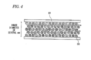
- FIG. 4 is a schematic diagram illustrating a related-art packed column such as one described above.
- the related-art packed column is formed by filling (packing) an absorbent 50 into a minute flow passage (tube) FP.
- a substance obtained by impregnating a carrier with low volatility liquid which will be referred to as stationary phase liquid or liquid phase
- an absorbent such as activated carbon, alumina or silica gel is packed into the minute flow passage formed by a glass tube or a metal tube.
- FIG. 5 is a schematic diagram illustrating a related-art capillary column such as one described above.
- the capillary column is formed by applying an absorbent 50 to an inner wall of a hollow minute flow passage (tube) FP.
- the related-art capillary column include: a WCOT (Wall Coated Open Tubular) type in which liquid phase is applied to an inner wall of a minute flow passage FP having an inner diameter of about 0.1 mm to about 1 mm; a PLOT (Porous Layer Open Tubular) type in which particulate porous polymer, alumina or the like having a diameter of several ⁇ m is carried in the form of a layer of about 5 ⁇ m to about 20 ⁇ m by a tube wall; and a SCOT (Support Coated Open Tubular) type in which a substance, obtained by impregnating a diatomaceous earth carrier having a grain size of several dozen ⁇ m with liquid phase, is carried in the form of a layer of several hundred
- a capillary column When a column has a capillary structure, a flow passage resistance is low, and the time taken to pass through the column is short. Hence, a capillary column has been advantageous in enabling a high speed chromatography analysis.
- the gas mixture serving as a sample for gas chromatography flows into the minute flow passage of the packed column or capillary column via an flow inlet 100 (not shown), and then flows through the minute flow passage of the packed column or capillary column while repeating absorption/desorption between an absorbent (stationary phase) packed into the minute flow passage or applied to an inner wall thereof and the inert gas (mobile phase) due to respective properties of gases contained in the gas mixture.
- a moving speed of the gas having a high absorptive property is low while a moving speed of the gas having a low absorptive property is high when the gas mixture moves through the column; therefore, a speed difference occurs between intrinsic gases, and the gases are discharged through a flow outlet 200 of the column in order of increasing absorptive property.
- the gas mixture i.e., each type of gas contained in the gas mixture (each gas component contained in the gas mixture)
- the gas chromatography apparatus in which the related-art packed column or capillary column is used is capable of performing gas mixture separation and conducting an analysis on each gas component.
- the absorbent such as activated carbon is used, thus causing a problem that pores of varying sizes, through which the gas serving as a sample is absorbed, are distributed, resulting in a cause of broadening of a peak separation.
- FIG. 6 is an explanatory diagram illustrating pore sizes of the absorbent in the related-art column.
- the absorbent such as activated carbon
- pores through which gas is absorbed are formed in such a manner that the pores having varying sizes, varying depths, varying diameters, etc. are distributed.
- Exemplary embodiments of the present invention address the above disadvantages and other disadvantages not described above.
- the present invention is not required to overcome the disadvantages described above, and thus, an exemplary embodiment of the present invention may not overcome any disadvantages
- the gas chromatograph column includes a flow passage through which gas subjected to gas chromatography is absorbed, wherein an inner wall surface of the flow passage is at least partially provided with a plurality of pores whose sizes are substantially uniform.
- a method of fabricating a gas chromatograph column including a flow passage through which gas subjected to gas chromatography is absorbed includes: (a) forming a groove in a first substrate made of silicon; (b) forming a plurality of pores in an inner wall surface of the groove, sizes of the pores being substantially uniform ; and (c) bonding a second substrate onto the first substrate such that the groove is covered by the second substrate, thereby forming the flow passage.
- a method of fabricating a gas chromatograph column including a flow passage through which gas subjected to gas chromatography is absorbed includes: (a) forming a groove in a first substrate made of silicon; (b) forming an aluminum thin film on an inner wall surface of the groove; (c) forming a plurality of pores in the aluminum thin film, sizes of the pores being substantially uniform; and (d) bonding a second substrate onto the first substrate such that the groove is covered by the second substrate, thereby forming the flow passage.
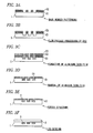
- FIGS. 1A and 1B are schematic diagrams illustrating a gas chromatograph column according to an embodiment of the present invention.
- FIG. 1A is a top view of the column
- FIG. 1B is a cross-sectional view of the column, taken along the line A-A of FIG. 1A .
- the gas chromatograph column mainly includes: a silicon substrate 1 that is one example of the first substrate having a minute groove for forming a minute flow passage through which gas serving as a sample flows; a substrate 2 that is made of Pyrex (registered trademark) glass or the like and is one example of the second substrate having a flow inlet 100 and a flow outlet 200 and affixed to the silicon substrate 1 to form a minute flow passage FP through which the gas serving as a sample flows; and a porous layer 3 that is provided with uniformly sized pores 31 and is formed porously by anodically oxidizing a surface of the minute groove or forming the surface of the minute groove into a porous structure.
- a silicon substrate 1 that is one example of the first substrate having a minute groove for forming a minute flow passage through which gas serving as a sample flows
- a substrate 2 that is made of Pyrex (registered trademark) glass or the like and is one example of the second substrate having a flow inlet 100 and a flow outlet 200 and
- the minute groove is formed in a serpentine or spiral manner at a center portion of the silicon substrate 1, by, for example, a RIE (Reactive Ion Etching) process, ultrasonic processing, laser processing, sandblast processing, wet etching, etc.
- the RIE process is a method for utilizing the effect of allowing an etching gas, ionized at relatively low pressure, to perpendicularly collide with a material, to be processed.
- this minute groove may be formed to have dimensions such as a width of 50 ⁇ m, a depth of 200 ⁇ m and a length of 10 m, for example. It should be noted that the groove of the silicon substrate 1 may be formed into a rectangle extended along a longitudinal direction thereof.
- the porous layer 3 is formed by anodically oxidizing the surface of the minute groove of the silicon substrate 1 or forming the surface of the minute groove of the silicon substrate 1 into a porous structure in a hydrofluoric acid aqueous solution.
- the pores 31 having uniform dimensions (size), diameter or depth are formed.
- the uniformly sized pores 31, each having a pore diameter of about several nm to about several tens of nm, are formed according to conditions. As illustrated in FIG.
- the uniformly sized pores 31 are formed by anodically oxidizing the surface of the minute groove of the silicon substrate 1 or forming the surface of the minute groove of the silicon substrate 1 into a porous structure in a hydrofluoric acid aqueous solution.
- the silicon substrate 1 provided with the groove for example, is impregnated with a hydrofluoric acid mixed solution containing 5% of hydrofluoric acid and 10% of IPA (isopropyl alcohol), and an electrical current is applied to a bottom portion of the groove at 5 mA/cm 2 for 10 minutes, thereby anodically oxidizing the surface of the groove or forming the surface of the groove into a porous structure.
- IPA isopropyl alcohol
- the porous layer 3 may, for example, made of a material such as porous silicon in which the surface of the minute groove of the silicon substrate 1 is anodically oxidized or formed into a porous structure, or porous aluminum in which an aluminum thin film formed on the surface of the minute groove of the silicon substrate 1 is anodically oxidized or formed into a porous structure in a hydrofluoric acid aqueous solution.
- the minute flow passage FP is formed by bonding (e.g,, thermocompression bonding or the like) the silicon substrate 1 and the substrate 2 to each other such that the flow inlet 100 and the flow outlet 200 formed in the substrate 2 are located at ends of the groove formed in the silicon substrate 1, and the groove formed in the silicon substrate 1 is covered with the substrate 2.
- the porous layer 3 may be formed in the substrate 2, the porous layer 3 may be formed over the entire surface of the minute flow passage FP, and an inner wall surface of the minute flow passage FP may be partially or entirely provided with a plurality of the uniformly sized pores.
- the porous layer 3 is not formed in the substrate 2, the gas passing through a region located close to the substrate 2 flows out of the column more rapidly.
- the formation of the porous layer 3 not only in the silicon substrate 1 but also in the substrate 2 is advantageous in enabling a reduction in broadening of a separation peak in chromatography.
- FIGS. 2A to 2D are explanatory diagrams (cross-sectional views) illustrating the method for fabricating the gas chromatograph column according to the present embodiment.
- components common to FIGS. 1A and 1B are denoted by the same reference characters, and the description thereof will be omitted herein.
- FIGS. 2A, 2B, 2C and 2D are the explanatory diagrams (cross-sectional views) illustrating the respective steps of fabricating the gas chromatograph column.
- a first mask member (protective film) 51 in which a hole is formed in a shape (such as a serpentine shape, a spiral shape or a rectangular shape extended along the longitudinal direction of the silicon substrate 1 ) viewed from an upper surface of the minute groove that forms the minute flow passage FP (mask member patterning).
- the first mask member 51 may be formed by a hydrofluoric-acid-resistant photoresist, silicon nitride film or the like.
- a RIE (Reactive Ion Etching) process is performed on the silicon substrate 1 covered with the first mask member (protective film) 51.
- the minute groove for forming the minute flow passage FP is formed in a region of the silicon substrate 1, which is not covered with the first mask member (protective film) 51, i.e., a region of the silicon substrate 1 corresponding to a region of the hole of the first mask member (protective film) 51, which is provided to have the shape viewed from the upper surface of the minute groove that forms the minute flow passage FP.
- the surface of the minute groove of the silicon substrate 1 is anodically oxidized or formed into a porous structure in a hydrofluoric acid aqueous solution, thereby forming the porous layer 3 provided with the pores 31 having uniform dimensions (size), diameter or depth.
- the silicon substrate 1 provided with the groove may be impregnated with a hydrofluoric acid mixed solution containing about 5% of hydrofluoric acid and about 10% of IPA (isopropyl alcohol), and an electric current is applied to a bottom portion of the groove at 5 mA/cm 2 for 10 minutes, thereby anodically oxidizing the surface of the groove or forming the surface of the groove into a porous structure.
- IPA isopropyl alcohol
- anodic oxidation may be performed in a hydrofluoric acid aqueous solution by using the silicon substrate 1 as an anode and using a platinum electrode or the like as a cathode.
- the silicon substrate 1 and the substrate 2 are bonded (e.g., thermocompression bonding) to each other such that the flow inlet 100 and the flow outlet 200 formed in the substrate 2 are located at the ends of the groove formed in the silicon substrate 1, and the groove formed in the silicon substrate 1 is covered with the substrate 2.
- the flow passage FP is formed.
- the groove formed in the silicon substrate 1 may be covered with the substrate 2 after removing the first mask member (protective film) 51.
- the porous layer 3 in which the uppermost surface of the minute groove formed in the silicon substrate 1 is porous silicon is formed in the gas chromatograph column according to the present embodiment.
- the inner wall surface of the minute flow passage may be partially or entirely formed by porous silicon.
- the gas chromatograph column includes: the first substrate that is made of silicon and provided with the minute groove for forming the minute flow passage; and the porous layer that is provided with the uniformly sized pores and is formed porously by anodically oxidizing the surface of the groove or forming the surface of the groove into a porous structure.
- the inner wall surface of the minute flow passage FP is partially or entirely provided with a plurality of the uniformly sized pores; thus, the absorptive property at the time of absorption and the time taken for absorption become constant (substantially constant) or variations thereof are reduced.
- the gas chromatograph column is advantageous in enabling a reduction in broadening of a separation peak in chromatography.
- the gas chromatograph column is advantageous in enabling an improvement in reproducibility of separation. Furthermore, the gas chromatograph column is also advantageous in that a flow passage blockage can be prevented by providing the foregoing structure.
- the method of fabricating the gas chromatograph column may include a step of forming the porous layer 3 in the substrate 2.
- the porous layer 3 is not formed in the substrate 2, the gas passing through a region located close to the substrate 2 flows out of the column more rapidly.
- the flowing speed of the gas becomes more uniform as compared with the foregoing case, and the absorptive property at the time of absorption and the time taken for absorption become constant (substantially constant) or variations thereof are reduced more effectively than the case where the porous layer 3 is formed only in the groove of the silicon substrate 1.
- the formation of the porous layer 3 not only in the silicon substrate 1 but also in the substrate 2 is advantageous in enabling a reduction in broadening of a separation peak in chromatography.
- the gas chromatograph column is used in a gas chromatography apparatus as described below, for example, to perform gas separation, thereby contributing to gas component analysis.
- An inert gas (mobile phase) such as helium is steadily flowed into the minute flow passage of the gas chromatograph column according to the present embodiment.
- a gas mixture serving as a sample for gas chromatography is flowed into the minute flow passage of the gas chromatograph column according to the present embodiment.
- the gas mixture Upon flow of the gas mixture, serving as a sample for gas chromatography, into the flow inlet 100 (not shown) of the minute flow passage FP, the gas mixture flows through the minute flow passage FP while repeating absorption/desorption due to properties of respective gases contained in the gas mixture.
- a moving speed of the gas having a high absorptive property is low while a moving speed of the gas having a low absorptive property is high when the gas mixture moves through the column. Therefore, a speed difference occurs between the intrinsic gases, and the gases are discharged through the flow outlet 200 of the column in order of increasing absorptive property.
- the gas mixture moves through the minute flow passage FP
- the gas mixture flows through the minute flow passage FP while repeating absorption/desorption via the porous layer 3 in which the pores provided on the minute groove constituting the minute flow passage FP are formed to have a uniform size.
- the absorptive property at the time of absorption and the time taken for absorption will be constant (substantially constant) or variations thereof will be reduced, and broadening of a separation peak in chromatography will be reduced.
- the gas mixture i.e., each type of gas contained in the gas mixture (each gas component contained in the gas mixture), can be more accurately analyzed.
- the gas chromatograph column includes: the first substrate that is made of silicon and provided with the minute groove for forming the minute flow passage; and the porous layer that is provided with the uniformly sized pores and is formed porously by anodically oxidizing the surface of the groove or forming the surface of the groove into a porous structure.
- the absorptive property at the time of absorption and the time taken for absorption become constant (substantially constant) or variations thereof are reduced.
- the gas chromatograph column is capable of reducing broadening of a separation peak in chromatography.
- the gas chromatograph column is advantageous in enabling a reduction in broadening of a separation peak in chromatography.
- the gas chromatograph column includes: the first substrate that is made of silicon and provided with the minute groove for forming the minute flow passage; and the porous layer that is provided with the uniformly sized pores and is formed porously by anodically oxidizing the surface of the groove or forming the surface of the groove into a porous structure, and therefore, the gas chromatograph column does not have a structure in which an absorbent is applied to an inner wall of the minute flow passage.
- the gas chromatograph column is advantageous in enabling an improvement in reproducibility of separation.
- the gas chromatograph column is also advantageous in that a flow passage blockage can be prevented by providing the foregoing structure.
- carbon, aluminum or alumina may be sputtered on the surface of the porous layer 3, the surface of the porous layer 3 may be oxidized, or the surface of the porous layer 3 may be coated with a solution by which a vitreous material is formable, thereby forming an "absorption performance enhancing layer".
- carbon may be sputtered on the porous layer 3 made of porous silicon, i.e., the surface of the minute groove for forming the minute flow passage.
- the gas chromatograph column is advantageous in enabling obtainment of absorption performance equivalent to that of activated carbon known as a typical absorbent, and thus can contribute to more accurate gas component analysis.
- the uppermost surface of the porous layer 3 made of porous silicon i.e., the surface of the minute groove for forming the minute flow passage
- the gas chromatograph column can obtain an absorptive property equivalent to that of alumina known as a typical absorbent, and thus can contribute to more accurate gas component analysis.
- the "absorption performance enhancing layer" may be formed by sputtering alumina on the surface of the porous layer 3 made of porous silicon.
- the gas chromatograph column can obtain an absorptive property (e.g., a property suitable for gas separation between N 2 and O 2 , a property capable of preventing the outflow of CO 2 by tightly absorbing CO 2 or the like) equivalent to that of zeolite known as a typical absorbent, and thus can contribute to more accurate gas component analysis.
- the porous layer 3 made of porous silicon i.e., the surface of the minute groove for forming the minute flow passage, may be oxidized, or may be coated with a solution by which a vitreous material such as polysilazane is formable.
- the porous layer 3 made of porous silicon is oxidized or the porous layer 3 is coated with a solution by which a vitreous material such as polysilazane is formable, thereby forming the "absorption performance enhancing layer”; thus, the gas chromatograph column can obtain an absorptive property equivalent to that of silica gel known as a typical absorbent, and can contribute to more accurate gas component analysis.
- the pore size can be adjusted depending on a current density and/or a hydrofluoric acid concentration, and selectivity for gases can be changed.
- the inner wall surface of the minute flow passage may be partially or entirely formed by porous aluminum (i.e., aluminum that is anodically oxidized or formed into a porous structure).
- FIGS. 3A to 3F are explanatory diagrams (cross-sectional views) illustrating another method of fabricating the gas chromatograph column according to the embodiment, in which an inner wall surface of a minute flow passage is partially or entirely formed by porous aluminum.
- FIGS. 3A to 3F components common to FIGS. 1A and 1B and FIGS. 2A to 2D are denoted by the same reference characters, and the description thereof will be omitted herein.
- FIGS. 3A, 3B, 3C, 3D, 3E and 3F are the explanatory diagrams (cross-sectional views) illustrating respective steps of fabricating the gas chromatograph column.
- a first mask member (protective film) 51 in which a hole is formed in a shape (such as a serpentine shape, a spiral shape or a rectangular shape extended along a longitudinal direction of the silicon substrate 1) when viewed from an upper surface of a minute groove that forms a minute flow passage FP (first mask member patterning).
- a second mask member (protective film) 52 in which a hole is formed in the shape viewed from the upper surface of the minute groove that forms the minute flow passage FP (second mask member patterning).
- the minute groove for forming the minute flow passage FP is formed in a region of the silicon substrate 1, which is not covered with the first and second mask members (protective films) 51 and 52, i.e., a region of the silicon substrate 1 corresponding to regions of the holes of the first and second mask members (protective films) 51 and 52, each of which is formed to have the shape viewed from the upper surface of the minute groove that forms the minute flow passage FP.
- an aluminum thin film 53 is formed over the surface of the first mask member (protective film) 51, the surface of the second mask member (protective film) 52, and the surface of the minute groove of the silicon substrate 1.
- the aluminum thin film 53 formed on the surface of the second mask member (protective film) 52, and the second mask member (protective film) 52 are removed. That is, the aluminum thin film 53 is formed only on the surface of the minute groove of the silicon substrate 1.
- the aluminum thin film 53 formed on the surface of the minute groove of the silicon substrate 1 is anodically oxidized or formed into a porous structure in a hydrofluoric acid aqueous solution, thereby forming a porous layer 3 provided with uniformly sized pores 31.
- the aluminum thin film 53 formed on the surface of the groove of the silicon substrate 1 may, for example, be impregnated with a hydrofluoric acid mixed solution containing about 5% of hydrofluoric acid and about 10% of IPA (isopropyl alcohol), and an electrical current may be applied to the aluminum thin film 53 at 5 mA/cm 2 for 10 minutes, for example, thereby anodically oxidizing the surface of the groove or forming the surface of the groove into a porous structure.
- IPA isopropyl alcohol
- the silicon substrate 1 and a substrate 2 are bonded (e.g., thermocompression bonding) to each other such that a flow inlet 100 and a flow outlet 200 formed in the substrate 2 are located at ends of the groove formed in the silicon substrate 1, and the groove formed in the silicon substrate 1 is covered with the substrate 2.
- the flow passage FP is formed.
- the groove formed in the silicon substrate 1 may be covered with the substrate 2 after removing the first mask member (protective film) 51.
- the porous layer 3 in which the uppermost surface of the minute groove formed in the silicon substrate 1 is porous aluminum, is formed in the gas chromatograph column according to the present embodiment.
- the inner wall surface of the minute flow passage is partially or entirely formed by porous aluminum.
- the gas chromatograph column includes: the first substrate that is made of silicon and provided with the minute groove for forming the minute flow passage; and the porous layer that is provided with the uniformly sized pores and is formed porously by anodically oxidizing the surface of the groove or forming the surface of the groove into a porous structure.
- the absorptive property at the time of absorption and the time taken for absorption become constant (substantially constant) or variations thereof are reduced.
- the gas chromatograph column since the inner wall surface of the minute flow passage FP is partially or entirely provided with a plurality of the uniformly sized pores, the absorptive property at the time of absorption and the time taken for absorption become constant (substantially constant) or variations thereof are reduced; hence, the gas chromatograph column is advantageous in that it is possible to reduce broadening of a separation peak in chromatography.
- the gas chromatograph column includes: the first substrate that is made of silicon and provided with the minute groove for forming the minute flow passage; and the porous layer that is provided with the uniformly sized pores and is formed porously by anodically oxidizing the surface of the groove or forming the surface of the groove into a porous structure, and therefore, the gas chromatograph column does not have a structure in which an absorbent is applied to an inner wall of the minute flow passage.
- the gas chromatograph column is advantageous in an improvement in reproducibility of separation.
- the gas chromatograph column is also advantageous in that a flow passage blockage can be prevented by providing the foregoing structure.
- the surface of the porous layer 3 may be oxidized, thereby forming an "absorption performance enhancing layer".
- the surface of the porous layer 3 made of porous aluminum may be oxidized.
- the "absorption performance enhancing layer” is formed by oxidizing the surface of the porous layer 3 made of porous aluminum (i.e., the surface of the minute groove for forming the minute flow passage) in this manner, the gas chromatograph column can obtain an absorptive property equivalent to that of alumina known as a typical absorbent, and thus can contribute to more accurate gas component analysis.
Landscapes
- Chemical & Material Sciences (AREA)
- Analytical Chemistry (AREA)
- Immunology (AREA)
- Pathology (AREA)
- Health & Medical Sciences (AREA)
- Biochemistry (AREA)
- General Health & Medical Sciences (AREA)
- General Physics & Mathematics (AREA)
- Physics & Mathematics (AREA)
- Life Sciences & Earth Sciences (AREA)
- Engineering & Computer Science (AREA)
- Nanotechnology (AREA)
- General Chemical & Material Sciences (AREA)
- Oil, Petroleum & Natural Gas (AREA)
- Chemical Kinetics & Catalysis (AREA)
- Solid-Sorbent Or Filter-Aiding Compositions (AREA)
Applications Claiming Priority (2)
| Application Number | Priority Date | Filing Date | Title |
|---|---|---|---|
| JP2009278192 | 2009-12-08 | ||
| JP2010265132A JP2011141271A (ja) | 2009-12-08 | 2010-11-29 | ガスクロマトグラフ用カラム及びその製造方法 |
Publications (1)
| Publication Number | Publication Date |
|---|---|
| EP2333539A1 true EP2333539A1 (fr) | 2011-06-15 |
Family
ID=43533184
Family Applications (1)
| Application Number | Title | Priority Date | Filing Date |
|---|---|---|---|
| EP10194013A Withdrawn EP2333539A1 (fr) | 2009-12-08 | 2010-12-07 | Colonne de chromatographe à gaz et son procédé de fabrication |
Country Status (4)
| Country | Link |
|---|---|
| US (1) | US20110132196A1 (fr) |
| EP (1) | EP2333539A1 (fr) |
| JP (1) | JP2011141271A (fr) |
| CN (1) | CN102087254A (fr) |
Families Citing this family (9)
| Publication number | Priority date | Publication date | Assignee | Title |
|---|---|---|---|---|
| CN103776940A (zh) * | 2012-10-19 | 2014-05-07 | 中国科学院电子学研究所 | 一种超大接触面积的阵列化微型气相色谱柱芯片 |
| KR101401342B1 (ko) * | 2012-12-13 | 2014-05-29 | 한국기초과학지원연구원 | 다중 에칭을 통한 가스 크로마토그래피 칩 적층체의 제조 방법 |
| FR3009384B1 (fr) * | 2013-07-31 | 2017-03-10 | Commissariat Energie Atomique | Procede de fabrication d'une colonne de chromatographie en phase gazeuse et colonne obtenue par un tel procede |
| US10073068B2 (en) * | 2013-09-18 | 2018-09-11 | Agilent Technologies, Inc. | Liquid chromatography columns with structured walls |
| JP2015184100A (ja) * | 2014-03-24 | 2015-10-22 | セイコーエプソン株式会社 | 物理量センサー、物理量センサーの製造方法、圧力センサー、高度計、電子機器および移動体 |
| BE1025524B1 (nl) | 2017-09-04 | 2019-04-05 | PharmaFluidics N.V. | Chemische reactoren |
| WO2022103085A1 (fr) * | 2020-11-16 | 2022-05-19 | 홍익대학교 산학협력단 | Système de mesure pour la surveillance de processus |
| TWI738581B (zh) * | 2020-12-03 | 2021-09-01 | 國立臺灣師範大學 | 平板式氧化鋁氣相層析管柱及其製作方法 |
| CN114699876B (zh) * | 2022-06-01 | 2022-12-23 | 天津理工大学 | 一种混合气体分离装置 |
Citations (6)
| Publication number | Priority date | Publication date | Assignee | Title |
|---|---|---|---|---|
| EP0310867A2 (fr) * | 1987-10-05 | 1989-04-12 | Shimadzu Techno-Research Inc. | Colonne chromatographique |
| DE19514033A1 (de) * | 1995-04-13 | 1996-10-17 | Huels Chemische Werke Ag | Verfahren zur Untersuchung silanbehandelter, anorganischer Materialien |
| US5620603A (en) * | 1994-02-04 | 1997-04-15 | Supelco, Inc. | Nucleophilic bodies bonded to siloxane and use thereof for separations from sample matrices |
| EP1329714A1 (fr) * | 2000-09-25 | 2003-07-23 | Gl Sciences Incorporated | Procede et dispositif servant a recueillir et a concentrer un echantillon |
| WO2007041550A2 (fr) * | 2005-09-30 | 2007-04-12 | Owlstone Nanotech, Inc. | Nanostructures contenant des nanotubes de carbone et procedes de synthese et d'utilisation de ceux-ci |
| US20090178563A1 (en) * | 2008-01-16 | 2009-07-16 | The Regents University Of Illinois | Column Design for Micro Gas Chromatograph |
Family Cites Families (3)
| Publication number | Priority date | Publication date | Assignee | Title |
|---|---|---|---|---|
| JP3554181B2 (ja) * | 1998-03-31 | 2004-08-18 | 京セラ株式会社 | 流体分離装置およびその形成方法 |
| JP2001343377A (ja) * | 2000-05-31 | 2001-12-14 | Meidensha Corp | キャピラリカラム及びそれを用いたクロマトグラフィ装置 |
| JP4314109B2 (ja) * | 2003-12-15 | 2009-08-12 | キヤノン株式会社 | 物質分離素子及びその製造方法 |
-
2010
- 2010-11-29 JP JP2010265132A patent/JP2011141271A/ja active Pending
- 2010-12-07 US US12/961,995 patent/US20110132196A1/en not_active Abandoned
- 2010-12-07 EP EP10194013A patent/EP2333539A1/fr not_active Withdrawn
- 2010-12-08 CN CN2010105883934A patent/CN102087254A/zh active Pending
Patent Citations (6)
| Publication number | Priority date | Publication date | Assignee | Title |
|---|---|---|---|---|
| EP0310867A2 (fr) * | 1987-10-05 | 1989-04-12 | Shimadzu Techno-Research Inc. | Colonne chromatographique |
| US5620603A (en) * | 1994-02-04 | 1997-04-15 | Supelco, Inc. | Nucleophilic bodies bonded to siloxane and use thereof for separations from sample matrices |
| DE19514033A1 (de) * | 1995-04-13 | 1996-10-17 | Huels Chemische Werke Ag | Verfahren zur Untersuchung silanbehandelter, anorganischer Materialien |
| EP1329714A1 (fr) * | 2000-09-25 | 2003-07-23 | Gl Sciences Incorporated | Procede et dispositif servant a recueillir et a concentrer un echantillon |
| WO2007041550A2 (fr) * | 2005-09-30 | 2007-04-12 | Owlstone Nanotech, Inc. | Nanostructures contenant des nanotubes de carbone et procedes de synthese et d'utilisation de ceux-ci |
| US20090178563A1 (en) * | 2008-01-16 | 2009-07-16 | The Regents University Of Illinois | Column Design for Micro Gas Chromatograph |
Non-Patent Citations (3)
| Title |
|---|
| SHO NISHIYANIA ET AL.: "Parylene Stationary Phase for Micro Gas Chromatography Columns", THE 25TH SENSOR SYMPOSIUM, 2008, pages 154 - 157 |
| T. NAKAI ET AL.: "Micro fabricated Semi-Packed Gas Chromatography Column with Functionalized Parylene as the Stationary Phase", TWELFTH INTERNATIONAL CONFERENCE ON MINIATURIZED SYSTEMS FOR CHEMISTRY AND LIFE SCIENCES, 2008, pages 1790 - 1792 |
| TOSHIHIDE THARA ET AL.: "Capillary Gas Chromatography", 1997, ASAKURA PUBLISHING CO., pages: 1 - 53 |
Also Published As
| Publication number | Publication date |
|---|---|
| CN102087254A (zh) | 2011-06-08 |
| US20110132196A1 (en) | 2011-06-09 |
| JP2011141271A (ja) | 2011-07-21 |
Similar Documents
| Publication | Publication Date | Title |
|---|---|---|
| EP2333539A1 (fr) | Colonne de chromatographe à gaz et son procédé de fabrication | |
| US6454840B1 (en) | Separation-column unit for a gas-chromatograph and method for making the same | |
| JPWO2004081555A1 (ja) | 質量分析システムおよび分析方法 | |
| WO2008020593A1 (fr) | colonne pour chromatographie et son procédé de fabrication | |
| WO2005121774A2 (fr) | Ensemble microcolonne de separation haute performance et procede d'elaboration | |
| WO1999012626A1 (fr) | Chromatographe a microstructure a colonne rectangulaire | |
| WO2005032688A9 (fr) | Colonne multicapillaire pour la chromatographie et la preparation d'echantillon | |
| US20160001199A1 (en) | Chemical Reactor Device | |
| EP3218922B1 (fr) | Système d'extraction et d'analyse comprenant un dispositif d'extraction d'espèces volatiles à partir d'un liquide | |
| Zhang et al. | Paper spray mass spectrometry-based method for analysis of droplets in a gravity-driven microfluidic chip | |
| EP2764357B1 (fr) | Procédé de fabrication d'une microcolonne de séparation en silicium pour chromatographie ou chromatographie en phase gazeuse | |
| US8299426B2 (en) | Conductive conduits for chemical analyses, and methods for making such conduits | |
| Shakeel et al. | First reconfigurable MEMS separation columns for micro gas chromatography | |
| Sidelnikov et al. | Gas chromatography of the future: columns whose time has come | |
| Chan et al. | Semi-packed gas chromatography columns with density modulated pillars | |
| KR20240123968A (ko) | 분해능이 향상된 마이크로 가스크로마토그래피 장치 및 이에 사용되는 컬럼 | |
| US6762057B1 (en) | Separation apparatus including porous silicon column | |
| US20030189001A1 (en) | Open capillary column and manufacturing method thereof | |
| JP2008309642A (ja) | マイクロチップおよびこれを用いた分析方法 | |
| EP4271989B1 (fr) | Structures de colonne | |
| JP2000081406A (ja) | 極微少量フローセル、及びその製造方法 | |
| CN111278549A (zh) | 化学反应器 | |
| Lee et al. | High-performance MEMS-based gas chromatography column with integrated micro heater | |
| JPH0943223A (ja) | キャピラリカラム | |
| He et al. | Research progress on gas chromatography columns |
Legal Events
| Date | Code | Title | Description |
|---|---|---|---|
| PUAI | Public reference made under article 153(3) epc to a published international application that has entered the european phase |
Free format text: ORIGINAL CODE: 0009012 |
|
| AK | Designated contracting states |
Kind code of ref document: A1 Designated state(s): AL AT BE BG CH CY CZ DE DK EE ES FI FR GB GR HR HU IE IS IT LI LT LU LV MC MK MT NL NO PL PT RO RS SE SI SK SM TR |
|
| AX | Request for extension of the european patent |
Extension state: BA ME |
|
| 17P | Request for examination filed |
Effective date: 20111214 |
|
| 17Q | First examination report despatched |
Effective date: 20130311 |
|
| STAA | Information on the status of an ep patent application or granted ep patent |
Free format text: STATUS: THE APPLICATION IS DEEMED TO BE WITHDRAWN |
|
| 18D | Application deemed to be withdrawn |
Effective date: 20130702 |