EP2333558A1 - Formverriegelungsgreifsystem - Google Patents
Formverriegelungsgreifsystem Download PDFInfo
- Publication number
- EP2333558A1 EP2333558A1 EP10194263A EP10194263A EP2333558A1 EP 2333558 A1 EP2333558 A1 EP 2333558A1 EP 10194263 A EP10194263 A EP 10194263A EP 10194263 A EP10194263 A EP 10194263A EP 2333558 A1 EP2333558 A1 EP 2333558A1
- Authority
- EP
- European Patent Office
- Prior art keywords
- analyte
- multiwell plate
- rack
- station
- handler
- Prior art date
- Legal status (The legal status is an assumption and is not a legal conclusion. Google has not performed a legal analysis and makes no representation as to the accuracy of the status listed.)
- Granted
Links
Images














Classifications
-
- G—PHYSICS
- G01—MEASURING; TESTING
- G01N—INVESTIGATING OR ANALYSING MATERIALS BY DETERMINING THEIR CHEMICAL OR PHYSICAL PROPERTIES
- G01N35/00—Automatic analysis not limited to methods or materials provided for in any single one of groups G01N1/00 - G01N33/00; Handling materials therefor
- G01N35/0098—Automatic analysis not limited to methods or materials provided for in any single one of groups G01N1/00 - G01N33/00; Handling materials therefor involving analyte bound to insoluble magnetic carrier, e.g. using magnetic separation
-
- G—PHYSICS
- G01—MEASURING; TESTING
- G01N—INVESTIGATING OR ANALYSING MATERIALS BY DETERMINING THEIR CHEMICAL OR PHYSICAL PROPERTIES
- G01N35/00—Automatic analysis not limited to methods or materials provided for in any single one of groups G01N1/00 - G01N33/00; Handling materials therefor
- G01N35/0099—Automatic analysis not limited to methods or materials provided for in any single one of groups G01N1/00 - G01N33/00; Handling materials therefor comprising robots or similar manipulators
Definitions
- the present invention also relates to a system for purifying and analyzing an analyte, comprising
- the washing in step d) comprises aspirating and dispensing the washing buffer with a process head engaged to pipette tips.
- the transport system preferably transfers the receptacle and the rack from the first position to the second separate position.
- the second separate position comprises a magnetic separation station.
- the analytical system additionally preferably comprises an amplification station.
- the automated analyzer further comprises a separation station disposed in a second location.
- said separation station is constructed and arranged to receive said processing vessel holding said liquid sample and said rack holding pipette tips used in the sample dispensing station and to separate an analyte from other material present in the liquid sample.
- Another preferred embodiment of a separation station is a separation station comprising movable magnets.
- An automated analyzer (400) for use in performing a nucleic acid based amplification reaction is also disclosed.
- Said analyzer comprises a plurality of modules (401, 402, 403).
- One module is a processing module disposed at a first location within the analyzer constructed and arranged to separate a nucleic acid from other material in a sample.
- Said processing module comprises a separation device as herein described.
- the analyzer further comprises an amplification module disposed and arranged at a second location within the analyzer.
- the amplification module comprises a temperature-controlled incubator for incubating the contents of at least one receptacle, preferably of a multiwell plate comprising the separated nucleic acid and one or more amplification reagents for producing an amplification product indicative of the target nucleic acid in the sample.
- the analytical instrument preferably additionally comprises a liquid handling module (404, 500). Further embodiments and preferred embodiments of the analytical instrument are described herein, either separately or as combinations of embodiments. Preferred embodiments of analyzers are shown in Figs. 38 and 51 .
- module and “cell” are used interchangeably herein.
- a tip rack is disclosed.
- Such tip racks comprise pipette tips.
- Tip racks are commonly used in analytical systems for providing pipette tips for pipetting liquids to the system.
- Such tips are disposable, but can be re-used at least once.
- Said tip rack comprises independent chambers for accommodating pipette tips.
- a preferred rack for holding pipette tips.
- Said rack comprises independent chambers for accommodating at least a first type of pipette tips and a second type of pipette tips.
- said rack comprises more than one part.
- said rack is an integral one part rack.
- the volume of the first type of pipette tips is at least 1 ml and the volume of the second type of pipette tips is below 1 ml. More preferably, the volume of the first type of pipette tips is between 1 ml and 1.5 ml, and the volume of the second type of pipette tip is between 10 ul and 600 ul.
- the rack is, thus, suited for holding more than one type of pipette tips. This is useful in systems in which different volumes of liquid are pipetted with pipette tips.
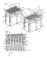
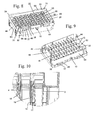
- Upper rack (1) comprises a frame (50) and a surface plate (51) located inside said frame (50) ( Fig. 9, Fig. 10 ).
- Said surface plate (51) comprises through bore-holes (23, 25) ( Fig. 4 ).
- separation walls (16) and separation lamellae (18) are located between through bore-holes (23, 25). They provide additional protection against contamination between tips (3, 4) and confer additional stability on the upper rack (1).
- Certain separation walls (16) also comprise a recess (13). Said recess (13) allows the separation walls (15) of the insert rack (14) to engage with separation walls (16) of the upper rack (1) in an overlapping way for sealing against horizontal flying drops in case of exploded bubbles during tip handling with tip (4).
- separation lamellae (18) with recess (13) alternate with separation lamellae (18) without recess.
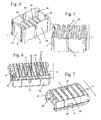
- chambers (19) comprise a wall (5) located on the inside surface (65) ( Fig. 24 ).
- Said wall (5) preferably covers only part of the height of chamber (19). More preferably, said wall (5) extends from above the bottom (21) of chamber (19) to below ridge (9) of the inside surface (65) of walls (54) of the lower rack (2). Said wall (5) further prevents capillary effects in chamber (19).
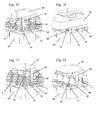
- the upper rack (1) preferably comprises a first type of positioning elements (10) ( Fig 21, Fig. 22 ) and a second type of positioning elements (31, 32, 33, 34) ( Fig. 17, Fig. 18 ).
- the first type of positioning elements (10) allows an approximate positioning of the rack (60) relative to a process head (35), while the second type of positioning elements (31, 32, 33, 34) allows a precise positioning of said rack (60) relative to the process head (35).
- the approximate positioning by the first type of positioning elements (10) ensures that the second type of positioning elements (31, 33) or (32, 34) are aligned with counter-positioning elements (36) on the process head (35).
- the advantage of the two types of positioning elements is that the positioning of rack (60) and process head (35) for tip engagement is fast and precise.
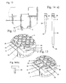
- the positioning elements (31, 33) engage with counter-positioning elements (36) on the process head (35) to align the first type of pipette tips (4) with the interface on the process head (35) ( Fig. 17, Fig. 18 ).
- positioning elements (32, 34) engage with counter-elements (36) on the process head (35) to align the second type of pipette tips (3) with the interface (67) of the process head (35) ( Fig. 19, Fig. 20 ).
- the positioning elements are openings (31, 32, 33, 34) in the top surface (51) of the rack (60), preferably located in opposite corners of the top surface (51) of the rack ( Fig. 1 ).
- the counter-positioning elements, in this preferred embodiment, on the bottom surface (61) of the process head (35) are rods (36) located in the corresponding corners of the process head (35). Openings (31, 32, 33, 34) and rods (36) are constructed such that rods (36) can engage with openings (31, 32 or 33, 34) for precise alignment of rack (60) and process head (35).
- Upper rack (1) and lower rack (2) are fixed during assembly, preferably by a snap-fit (44) located on either one of two opposite side walls (63, 64) of the frame of the upper rack (1) and a snap groove (45) located on either one of two corresponding opposite side walls of the lower rack (2).
- Analytical systems used in the field of diagnostics require processing of samples to be analysed. Such processing involves transfer of vessels, or of liquid samples and reagents from one vessel to another. For higher throughput, simultaneous processing is often performed with processing devices which can handle multiple consumables simultaneously. Engagement of process device and consumables requires proper alignment.
- a positioning method for aligning a rack and a process device comprises aligning at least two positioning elements located on the bottom surface of said process device with at least two positioning elements located on the top surface of said rack, and mechanically engaging said positioning elements on the process device with the positioning elements of the rack.
- Process devices preferably relate to pipettor for engaging with pipette tips to pipette liquids. Such process heads are well known in the art.
- the engagement of the positioning elements on the process device and the positioning elements on the consumable cause the interface of the process device to interact and engage with the pipette tips.
- a "rack” is understood to be any type of device used in an analytical system which holds a sample, a device which holds a consumable which is constructed and arranged to hold a sample.
- the rack has a top surface and four sidewalls, wherein two side walls are parallel and opposing each other.
- the rack also has a bottom surface.
- a consumable is understood to be a device which is introduced recurrently to the analytical system for use in an analytical test. A consumable may be used a single time before being replaced, or it may be use multiple times.
- said rack holds vessels. Said vessels can hold a sample for use in an analytical system.
- Said sample is understood to relate to a sample to be processed in an analytical system, or a reagent to be used in an analytical system.
- one positioning element on the rack located in one corner has a first shape and the second positioning element on the rack which is mounted on the diagonally opposite corner of said top surface of said tip rack has a second shape.
- the first shape is a circular cross-section and the second shape is an elongated shape.
- the method may also include a a first positioning step, wherein the positioning elements located on the bottom surface of said process device and the positioning elements located on the top surface of said rack are aligned.
- the first positioning is mediated by engagement of said positioning element with a notch.
- said process head (35) comprises a number of interfaces (67) equal to the number of pipette tips of a first type (4).
- Said interfaces (67) may be conical or cylindrical, and may preferably comprise an O-ring.
- at least two positioning elements (31, 32, 33, 34) on the tip rack (60, 70) engage with at least two positioning elements (36) on the process head (35) such that the process head (35) only engages with pipette tips of a first (4) or with pipette tips of a second (3) type.
- said positioning elements (31, 32, 33, 34, 36) are located in diagonally opposite corners of said process device (35) or said rack (60, 70).
- the tip rack (60, 70) comprises an equal number of first pipette tips (4) and second pipette tips (3).
- one positioning element (31, 32) on the rack (60, 70) located in one corner is a circular opening
- the corresponding second positioning element (33, 34) on the rack which is mounted on the diagonally opposite corner of the top surface of said tip rack (60, 70) is an oval opening.
- a method for isolating and processing an analyte that may be present in a fluid sample comprises the automated steps of:
- said multiwell vessel is a multiwell plate.
- the method additionally comprises the step of analyzing the purified analyte in a analyzing station. More preferably, the analyzing is performed in a second multiwell plate. Even more preferably, said second multiwell plate is contacted by at least one handler, preferably a handler, and transported between stations, wherein said contact between said handler and said multiwell vessel is a form-locking contact.
- the handler preferably transports the multiwell vessel between two stations, or between three stations. Said stations are preferably a storage station and/or a sample station and/or a separation station and/or a holding station and/or a sealing station and/or an analyzing station, and/or a detection station.
- the method additionally comprises the step of providing pipette tips in a tip rack, wherein said tip rack is contacted by at least one handler and transported between stations, wherein said contact between said at least one handler and said tip rack vessel is a form-locking contact.
- One of the stations is preferably a storage station. Other preferred stations are the stations described herein.
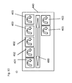
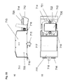
- said handler comprises gripper fingers, wherein said gripper fingers fit with a recess of the multiwell plate, wherein said fit is form-locking.
- a system for purifying and analyzing an analyte is, furthermore, disclosed, comprising a processing cell comprising a separation station for separating an analyte comprised in a vessel of a multiwell plate from a solid support material.
- said separation station is constructed and arranged to separate an analyte comprised in a vessel of a multiwell plate from a solid support material.
- An improved multiwell plate for optimal use in an automated analytical system is provided.
- adjacent vessels within one row are joined on the longer side of said almost rectangular shape.
- the top surface comprises ribs, wherein said ribs surround the openings of the vessels.
- one shorter side of said upper part of the vessels comprises a recess, said recess comprising a bent surface extending from the rib to the inside of the vessel.
- the base preferably comprises a rim comprising recesses. Latch clips on a station of an analyzer can engage with said recesses to fix the plate on a station.
- the processing plate (101) preferably comprises hardware-identifiers (102) and (115).
- the hardware identifiers (102) and (115) are unique for the processing plate (101) and different from hardware identifiers of other consumables used in the same system.
- the hardware identifiers (102, 115) preferably comprise ridges (119) and/or recesses (125) on the side walls of the consumables, wherein said pattern of ridges (119) and/or recesses (125) is unique for a specific type of consumable, preferably the processing plate (101). This unique pattern is also referred to herein as a unique "surface geometry".
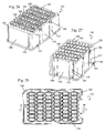
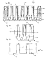
- the center part (120) of the vessels (103) has an almost rectangular cross section ( Fig. 30, Fig. 31 ). They are separated along the longer side (118) of the almost rectangular shape by a common wall (113) ( Fig. 37 ).
- the row of vessels (103) formed thereby has the advantage that despite the limited space available, they have a large volume, preferably of 4 ml. Another advantage is that because of the essentially constant wall thickness, the production is very economical. A further advantage is that the vessels (103) strengthen each other and, thus, a high stability of the shape can be obtained.
- a continuous space (121) is located ( Fig. 31 , Fig. 35 ).
- the space (121) can accommodate magnets (122) or heating devices (128) ( Fig. 36 , Fig. 38 ).
- These magnets (122, 127) and heating devices (128) are preferably solid devices.
- magnetic particles (216) comprised in liquids (215) which can be held in the vessels (103) can be separated from the liquid (215) by exerting a magnetic field on the vessels (103) when the magnets (122, 127) are brought into proximity of the vessels (103).
- the contents of the vessels (103) can be incubated at an elevated, controlled temperature when the processing plate (101) is placed on the heating device (128).
- the space (121) is even more pronounced and can accommodate further magnets (127).
- the combination of the large magnets (122) in the upper area and the smaller magnets (127) in the conical area of the vessels (3) allows separation of magnetic particles (216) in larger or small volumes of liquid (215).
- the small magnets (127) thus, make it easier to sequester the magnetic particles (216) during eluate pipetting. This makes it possible to pipette the eluate with minimal loss by reducing the dead volume of the magnetic particle (216) pellet. Furthermore, the presence of magnetic particles (216) in the transferred eluate is minimized.
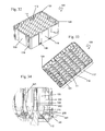
- one of the shorter side walls (109) of the vessel (103) comprises an reagent inlet channel (105) which extends to the circumferential rib (104) ( Fig. 32 , Fig. 30 ).
- the reagents are pipetted onto the reagent inlet channel (105) and drain off the channel (105) into the vessel (103).
- contact between the pipette needle (80) or tip (3, 4) and liquid contained in the vessel is prevented.
- splashes resulting from liquid being directly dispensed into another liquid (215) contained in the vessels (103), which may cause contamination of the pipette needle (80) or tip (3, 4) or neighboring vessels (103) is prevented.
- the vertical latch forces can also neutralize any deformations of the processing plate (101) leading to a more precise positioning of the spherical bottoms (111) within the processing station (201).
- the precise interface between the processing plate (101) and the processing station (201) or heating device (128) within an analyzer (126) reduces dead-volumes and also reduces the risk of sample cross-contamination.
- the fixture comprises at least one magnet generating a magnetic field.
- a moving mechanism is present which vertically moves said at least one fixture comprising at least one magnet at least between first and second positions with respect to the vessels of the multiwell plate.
- said at least two Z-positions of the vessels comprise the side walls and the bottom part of said vessels.
- the magnetic field of said at least one magnet preferably draws the magnetic particles to an inner surface of the vessel adjacent to said at least one magnet when said at least one magnet is in said first position.
- the effect of said magnetic field is less when said at least one magnet is in said second position than when said at least one magnet is in said first position.
- the fixture comprising said at least one magnet comprises a frame.
- the vessels have preferred features as described under Multiwell plate/ Processing plate. One such preferred feature is that at least a part of said vessels has a substantially rectangular cross-section orthogonal to the axis of said vessels.
- the separation station comprises a frame to receive the multiwell plate, and latch-clips to attach the multiwell plate.
- the separation station comprises two types of magnets. This preferred embodiment is further described below.
- a second preferred embodiment is described below, which comprises a spring which exerts a pressure on the frame comprising the magnets such that the magnets are pressed against the vessels of the multiwell plate.
- a method of isolating and purifying an analyte, preferably a nucleic acid comprises the steps of binding an analyte to magnetic particles in a vessel of a multiwell plate.
- the vessel comprises an upper opening, a central part and a bottom part.
- the bound material is then separated from unbound material contained in a liquid when the major part of the liquid is located above the section where the conical part of the vessel is replaced by the central part with the rectangular shape, by moving a magnet from a second position to a first position and, in said first position, applying a magnetic field to the central part and, optionally, additionally applying a magnetic field to the bottom part of said vessel.
- the magnetic particles can optionally be washed with a washing solution.
- a small volume of liquid, wherein the major part of the liquid is located below the section where the conical part of the vessel is replaced by the central part with the rectangular shape is separated from said magnetic particles by selectively applying a magnetic field to the bottom part of said vessel.
- the method hereinbefore described preferably additionally comprises between steps c) and d) the step of eluting said nucleic acid.
- the method comprises the step of transferring said eluate from a said multiwell plate to a second multiwell plate.
- a first type of magnet is moved from a second position to a first position to apply a magnetic field to a central part of the vessel, and, optionally, a second type of magnet is moved to the bottom part of the vessel to apply a magnetic field. More preferably, a magnet is moved to the central part of the vessel for step b), and the magnet is moved to the bottom part of said vessel into a third position for eluting said nucleic acid.
- a first preferred embodiment of a separation station (201) is described below.
- the first preferred embodiment of said separation station (201) comprises at least two types of magnets (202, 203).
- the first, long type of magnet (202) is constructed and arranged to fit into the space (121) of the processing plate (101).
- Magnet (202) thus, exerts a magnetic field on the liquid (215) in the vessel (103) to sequester magnetic particles (216) on the inside of the vessel wall. This allows separation of the magnetic particles (216) and any material bound thereto and the liquid (215) inside the vessel (103) when a large volume of liquid (215) is present.
- Magnet (202) has an elongated structure and is constructed and arranged to interact with the essentially rectangular central part (120) of the vessel.
- magnet (202) is used when the major part of the liquid (215) is located above the section where the conical part (111) of the vessel (103) is replaced by the central part (120) with the rectangular shape.
- the preferred construction of the magnets (202) comprises fixtures (204, 204a) comprising magnets (202) which fit into the space (121) between the rows of vessels (103) in the processing plate (101).
- Another preferred embodiment of magnets (202) comprises magnets (202) arranged on fixtures (204, 204a).
- the magnets (203) of the preferred separation station (201) are smaller, and can interact with the conical part (111) of the vessel (103). This is shown in Fig. 41 (a) .
- the magnets (202, 203) are movable.
- the separation station (201) comprises a mechanism to move the fixtures (204, 204a) and the bases (205). All fixtures (204, 204a) are interconnected by a base (217) and are, thus, moved coordinately. All magnets (203) are joined to one base (218) and are, thus, moved coordinately.
- the mechanism for moving the magnetic plates (202) and (203) is constructed and arranged to move the two types of magnetic plates (202, 203) to a total of four end positions:
- the base (217) of magnets (202) is connected to a positioning wheel (206).
- the base (217) comprises a bottom end (207) which is flexibly in contact with a connecting element (208) by a moving element (209).
- Said moving element is constructed and arranged to move the connecting element (208) along a rail (212) from one side to the other.
- Said moving element (209) is fixed to the connecting element (208) with a pin (220).
- Said connecting element (208) is fixed to the positioning wheel (206) by screw (210).
- Connecting element (208) is also connected to axis (211).
- Said connecting element (208) is preferably a rectangular plate.
- the base (218) is mounted on a bottom part (219) and is connected, at its lower end, with pin (213) to a moving element (214), which is preferably a wheel, which interacts with the positioning wheel (206).
- wheel (214) moves along positioning wheel (206).
- the magnets (203) are in their lowermost position.
- the location of the magnets (203) is controlled by the shape of the positioning wheel (206).
- moving element (209) moves along the central, rounded upper or lower part (212a) of rail (212)
- the small type of magnets (203) are moved up and down.
- the moving element (209) is located on the side (212b) of bottom end (207) and moves up or down, the magnets (202) are moved up- or downwards.
- the positioning wheel can be rotated by any motor (224).
- a spring (225) is attached to the base (222) of the separation station and the base (218) of magnets (203) to ensure that magnets (203) are moved into the lowermost position when they are moved downwards.
- the separation station (230) comprises at least one fixture (231) comprising at least one magnet (232), preferably a number of magnets equal to a number of vessels (103) in a row (123).
- the separation station (230) comprises a number of fixtures (231) equal to the number of rows (123) of the multiwell plate (101) hereinbefore described. More preferably, six fixtures (231) are mounted on the separation station (230). At least one magnet (232) is mounted on one fixture (231). Preferably, the number of magnets (232) equals the number of vessels (103) in one row (123). Most preferably, eight magnets (232) are mounted on one fixture (231).
- one type of magnet (232) is comprised on said fixture (231). More preferably, the magnet (232) is mounted on one side of the which is oriented towards the vessels with which the magnet interacts.
- the fixture (231) is mounted on a base (233).
- said mount is flexible.
- the base (233) comprises springs (234) mounted thereon.
- the number of springs (234) is at least one spring per fixture (231) mounted on said base (233).
- the base further comprises a chamfer (236) which limits the movement of the spring and, consequently, the fixture (231) comprising the magnets (232).
- any one of said springs (234) is constructed and arranged to interact with a fixture (231). More preferably, said spring (234) is a yoke spring. Said interaction controls the horizontal movement of the fixtures (231).
- the separation station (230) comprises a frame (235).
- the base (233) with fixtures (231) is connected to the frame (235) by a moving mechanism as described hereinbefore for the magnets (232) of the first embodiment.
- said base (233) and fixture (231) is constructed and arranged to move vertically (in Z-direction).
- the multiwell plate (101) hereinbefore described is inserted into the separation station (230).
- the fixture (231) comprising the magnets (232) is moved vertically. Any one fixture (232) is, thus, moved into a space (121) between two rows (123) of vessels (103).
- the vertical movement brings the magnets (232) mounted on a fixture (231) into contact with the vessels (103).
- the Z-position is chosen depending on the volume of liquid (215) inside the vessels (103).
- the magnets (232) contact the vessels (103) in a center position (120) where the vessels (103) are of an almost rectangular shape.
- the magnets (232) preferably contact the conical part (111) of the vessels (103).
- a spring is attached to the base (233) of any one frame (231) ( Fig. 39 a), b) ).
- the spring presses the magnets (232) against the vessels (103). This ensures a contact between magnets (232) and vessels (103) during magnetic separation.
- the magnet (232) contacts the vessel (103) on the side wall (109) located underneath the inlet (105). This has the advantage that liquid which is added by pipetting flows over the sequestered magnetic particles and ensures that particles are resuspended and that all samples in all vessels are treated identically.
- This embodiment is particularly suited to separate a liquid (215) comprised in a multiwell plate (101) as hereinbefore described, from magnetic particles (216) when different levels of liquid (215) are contained in the vessels (103) of said multiwell plate (101).
- multiwell plates are commonly used. Such plates are particularly useful in automated analytical systems which comprise an amplification station for amplifying nucleic acid analytes.
- An improved automated method for isolating and amplifying a nucleic acid, improved multiwell plate with a sealing foil and improved automated analytical system are disclosed herein.
- a method for isolating and amplifying a nucleic acid analyte that may be present in a fluid sample comprises separating said nucleic acid analyte from other material present in said fluid sample in a first vessel.
- said first vessel is comprised in a first multiwell plate.
- a second multiwell plate is provided.
- This second multiwell plate comprises a lid which comprises a frame and a sealing foil. The lid is lifted and then the separated analyte in the first vessel is transferred to a well of the second multiwell plate. The lid comprising said sealing foil is placed on the second multiwell plate. Then the second multiwell plate is sealed with the sealing foil. Once the second multiwell plate is sealed, the analyte is amplified in the presence of amplification reagents which were added prior to sealing, in said second multiwell plate.
- the lid is rotated by 180°.
- the frame comprises supporting ribs, more preferably four supporting ribs
- the multiwell plate comprises corresponding recesses, more preferably four corresponding recesses, wherein said recesses are positioned such that the supporting ribs of the frame do not align with the recesses in the first position of the lid on the multiwell plate, and that the supporting ribs do align with the recesses in the second position of the lid on the multiwell plate.
- the supporting ribs of the frame are preferably placed within the recesses of the multiwell plate.
- the sealing in step f) is heat sealing. Further preferred embodiments of the method are described hereinbefore or hereinafter.
- a multiwell plate set comprising a multiwell plate and a lid
- said lid comprises a frame and a sealing foil affixed to said frame, wherein in a first position of said lid on said multiwell plate, a separation distance is located between said sealing foil and the top surface of said multiwell plate, and in a second position, the sealing foil is in contact with said top surface of the multiwell plate.
- the frame comprises supporting ribs and the multiwell plate comprises openings, wherein, in said first position, the supporting ribs are in a different location than the openings, and in said second position, said supporting ribs and said openings align.
- the top surface of said multiwell plate comprises heat rims, and in said second position, the sealing foil contacts the heat rims.
- the sealing foil is affixed to the frame by a heat sealing method. More preferably, the sealing foil is affixed to the top surface of the frame.
- the sealing foil comprises a polymer.
- the sealing foil comprises at least two layers with different melting points. More preferably, the sealing foil comprises two layers with different melting points, wherein the layer with the lower melting point is oriented towards the multiwell plate. Further preferred embodiments of the method are described hereinbefore or hereinafter.
- An analytical system comprising a holding station and a multiwell plate as described herein is also disclosed, wherein said multiwell plate is fixed in said holding station.
- the analytical system additionally comprises a sealing station for heat-sealing of the sealing foil comprised in the frame to the multiwell plate.
- the exemplary multiwell plate with a frame comprises a multiwell plate (300) which comprises a multitude of vessels (312). Said vessels (312) are integrally formed on the upper surface (326) of the multiwell plate (301). On the upper surface (326) each vessel (312) is surrounded by an elevated heat rim (311).
- the lid (302) comprises a frame (302b) comprising a polymer (314) and a foil (303) comprising a polymer.
- the foil (303) is affixed to the frame (302b) by a heat sealing method.
- the foil (303) is sealed onto the top surface (302a), more preferably by heat sealing.
- the multiwell plate (300) comprises two long side walls (323, 324) which are opposite each other, and two short side walls (319, 320) which are opposite each other.
- the frame (302b) comprises two long side walls (328, 327) which are located opposite each other and two short side walls (321, 322) which are located opposite each other.
- the preferred foil (303) comprises two layers (314, 315) with different melting points.
- One layer (311) has a lower melting point.
- This layer (311) is oriented towards the multiwell plate (301) with the heat rims (310, 311) and the surface (302a) of the frame (302b).
- Heat is transferred through the more stable layer (310) with the higher melting point to layer (311) with the lower melting point.
- Layer (311) is, thus, heated and melted.
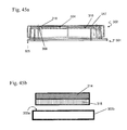
- the upper layer (310) is not melted during heat sealing. This minimizes the risk of a leaking foil (303) ( Fig. 45 b) ).
- the foil (303) when placed on the multiwell plate (301), the foil (303) is brought into contact with the heat rims (311) surrounding the vessels (312) of the multiwell plate (301), and heat can be applied to seal the vessels (312) with the foil (303) ( Fig. 44 d) , Fig. 45 a) ).
- Both microwell plate (301) and lid (302) comprise a length and width of the base corresponding to ANSI SBS footprint format. More preferably, the length is 127.76mm +/- 0.25 mm, and the width is 85.48 mm +/- 0.25 mm. They comprise openings (304) on plate (301) and openings (309) on lid (302) which are constructed and arranged to be gripped by a handler (500), either in pairwise arrangement or individually. Thus, it is possible to grip and transport the assembled plate and frame (300), or only the lid (302) or only the plate (301).
- the frame (302b) comprises a recess (307).
- This recess is located at the lower end of the side of the frame (302b).
- the recess is preferably located in a different position than openings (304).
- two recesses (307) are located on one side of the frame (302), and two recesses (307) are located on the opposite side of the frame (302b).
- said recesses (307) are located in the same position as recesses (306) on the multiwell plate (301).
- the recesses (307) ensure that when the plate (301) is fixed by engagement of fixing elements (124a) and recesses (306) only the multiwell plate (301) is fixed, not the lid (302).
- An analytical system (440) comprising an automated analytical apparatus (400) for isolating and / or analyzing an analyte is disclosed.
- An "analyte” as used herein relates to any type of analyte of interest.
- Preferred analytes are polypeptides or nucleic acids. More preferably, the analyte is a nucleic acid.
- the analytical system (440) further comprises more than one type of consumables (60, 70, 101,301,302), wherein said consumables (60, 70, 101,301,302) have essentially a same footprint, and wherein any type of consumables (60, 70, 101,301,302) comprises a unique surface geometry (601).
- the system also comprises a system comprising specific recognition elements for distinguishing said different consumables wherein any one of said recognition elements comprises a unique surface geometry complementary to a unique surface geometry of a specific type of consumable.
- said system for distinguishing said different consumables 60, 70, 101,301,302 constructed and arranged to recognize specifically said unique surface geometry (601).
- Consumables (60, 70,) with essentially identical footprint are plastic consumables for storing other consumables, such a pipette tips or single tubes, of for holding reagents and samples, or consumables (101,301,302) holding reaction mixes in which the processing or analyzing of the analyte are performed.
- Preferred embodiments of such consumables are racks (60, 70) or multiwell plates (101,301,302). Different types of multiwell plates (101,301,302) with identical footprint can preferably be used in the system (440).
- a "unique surface geometry” is understood to be a surface geometry (601) as hereinbefore described which is unique for a type of consumable (60, 70, 101,301,302) and is substantially different from the surface geometries (601) of other consumables (60, 70, 101,301,302) such that the consumable (60, 70, 101,301,302) is specifically recognized by the recognition system (450) of the analytical system (440).
- Individual consumables (60, 70, 101,301,302) of one type are then retrieved from the stacker (600a,b) within the system (440) and automatically transported to the module (401, 402, 403) in which they are used, either by a conveyor or, preferably by a handler (500) connected to a robotic arm (502).
- a specific type of consumable (60, 70, 101,301,302) can only be loaded into a specific stacker (600a,b). This prevents the user from loading the wrong consumable (60, 70, 101,301,302) into a specific stacker (600a,b), even if the consumables (60, 70, 101,301,302) have the same footprint.
- more than two different types of consumables (60, 70, 101,301,302) with a same footprint are comprised in the system (440).
- more than three different types of consumables (60, 70, 101,301,302) with a same footprint are comprised in the system (440).
- the consumables (60, 70, 101,301,302) are preferably selected from the group consisting of tip rack (60, 70), multiwell plate (101) for sample preparation, multiwell plate (302) for amplification and/or detection, reagent cassette holder, tube holder etc.
- a method for recognizing the identity of a consumable (60, 70, 101,301,302) within an analyzer (400) as described hereinbefore.
- Said method comprises providing one type of consumable (60, 70, 101,301,302), wherein said one type of consumable (60, 70, 101,301,302) comprises a unique surface geometry (601).
- the method further comprises interacting said one type of consumable (60, 70, 101,301,302) comprising a unique surface geometry (601) with a stacker (600a,b) comprising recognition elements (602) specific for said unique surface geometry (601).
- the consumable (60, 70, 101,301,302) is then identified when the unique surface geometry (601) is engaged by the recognition elements (602).
- a consumable 60, 70, 101,301,302
- a unique surface geometry 601 constructed and arranged to allow a stacker (600a,b) to specifically identify the type of consumable (60, 70, 101,301,302).
- Preferred embodiments of consumable (60, 70, 101,301,302), stacker (600a,b) and surface geometry (601) are as hereinbefore described.
- FIG. 51 A schematic drawing of an exemplary analytical system (440) is shown in Fig. (51 ).
- the recognition of the surface geometry (601) by the stacker (600a,b) is shown in Fig. 51 .
- the inner surface of the stacker (600a,b) comprises recognition elements (602). It is constructed and arranged to engage the surface geometry (601) of the consumable (60, 70, 101,301,302) and, thereby, the type of consumable (60, 70, 101,301,302) is specifically recognized and loading of the wrong type of consumable (60, 70, 101,301,302) is avoided.
- more than one type of multiwell plate is used in the analytical system (440), preferably in different steps of the analytical method.
- different types of multiwell plates (101,301,302) have different surface geometries that are unique for each type of multiwell plate (101,301,302).
- Each type of multiwell plate (101,301,302) is specifically recognized by its unique surface geometry (601).
- contamination protection may be further improved by combining the claimed method with any one of the known contamination methods described above.
- said first cell comprises a first air pressure
- said second cell comprises a second air pressure, wherein said first air pressure is higher than said second air pressure
- outside air which enters said first cell is filtered.
- Filtering of air allows to reduce the risk of contaminants entering the analytical apparatus.
- the filters are HEPA filters.
- said first and second cell are separated by a wall. Separation of cells by walls further reduces the risk of potential contaminants from one cell entering another cell.
- the purified analyte is transferred from said first cell to said second cell through an air-lock located between said first and second cell.
- the air lock comprises a door on the side of the first cell and a door on the side of the second cell. In the resting state of the air lock, both doors are on the closed position.
- the door on the side of the first cell opens when a plate has to pass from the first cell to the second cell.
- the plate is then placed on a movable plate holder. Said plate holder is then moved into the air lock.
- the door on the side of the first cell closes. Then, the door on the side of the second cell opens.
- the plate on the plate holder passes to the end of the air lock, and a handler then removes the plate from the plate holder of the air lock.
- said purified analyte is comprised in a reaction vessel.
- a additional step comprises transferring a sample from a sample vessel to a multiwell plate in a third cell, wherein said third cell has an air-flow which is separate from said first and second cell and wherein said step precedes the steps carried out in the first cell.
- the first cell is a processing cell as descried herein
- the second cell is an analytical cell as described herein
- the third cell is a sample cell as described herein.
- An automated analytical apparatus for processing an analyte comprising
- said first cell comprises a first air pressure and said second cell comprises a second air pressure, wherein said first air pressure is higher than said second air pressure.
- an air-lock is located between said processing cell and said analytical cell.
- said automated analytical apparatus additionally comprises a sample cell for transferring samples from a sample vessel to a processing vessel.
- said apparatus comprises separation walls located between said cells.
- said sample cell comprises a filter for filtration of air flowing in said sample cell.
- gaskets are comprised in the upper housing of said processing cell.
- reaction vessel is capped or sealed.
- said transfer system comprises a first handler for transferring said reaction vessel from said processing cell to said air-lock, and a second handler for transferring said reaction vessel from said air-lock to said analytical cell.
- a preferred embodiments of the apparatus is a automated nucleic acid analyzer comprising a process cell for sample preparation and an amplification cell.
- Sample cell (701) has an air-flow (741) and an air pressure (751), and process cell (742) has an air flow (742) and an air pressure (752), and amplification cell (703) has an air flow (743) and an air pressure (753).
- the air pressures (751) and (752) are essentially identical. Air pressure (752) is higher than air pressure (753), which prevents air from flowing from amplification cell (703) to process cell (702). Walls (731) to (734) are located between the three cells (701) to (703). An air lock (710) is located between process cell (702) and amplification cell (703).
- Fig 55 shows a side view (a) and a top view (b) of the air lock (710).
- the air lock (710) has a main body (723) and side walls (713) and a door (711) on the side of the process cell (702) and a second door (712) on the side of the amplification cell (703).
- the doors (711), (712) are movably attached to the main body by hinges (716).
- a movable carriage (714) is mounted inside the air lock (710).
- the carriage (714) comprises a plate holder (720).
- at least one teach-bolt (721), preferably more than one teach-bolt (721) is mounted.
- the teach-bolt (721) serves as an orientation for the handler when the handler is in the process of engaging the plate on the plate holder (720) or when moving the plate onto the plate holder (720).
- the carriage also comprises notches (721) which provide space for the gripper fingers of the gripper.
- the air-lock (710) also comprises gaskets (719) for proper closing of the closing of the doors (711), (712).
- the main body (723) further comprises, on each end, a mechanical stopper (718) for the doors (711) and (712). There is also a motor (715) attached to the main body (723) for moving the carriage (714).
- Fig. 56 shows a preferred apparatus.
- the apparatus comprises, on the front side, walls (761) and (762).
- the walls are movable to allow access to the cells (701), (702) for the handler system (704).
- the walls (761, 762) are made of foil. They can be moved up and down.
- the apparatus further comprises outer side walls (735).
- An analytical apparatus (400) for isolating and analyzing at least one analyte comprising
- the apparatus further comprises at least one transport module (480) for transferring consumables (60, 70, 101,301,302), wherein said at least one transport module (480) is arranged parallel to said axis in front of modules (i) to (iii).
- the at least one transport module (480) preferably comprises a handler (500) as described hereinafter.
- the apparatus (400) comprises at least one consumable holder (600), wherein said at least one consumable holder (600) is arranged along said axis in front of said modules (i) to (iii).
- said consumable holder (600) is a stacker (600).
- Said stacker (600) preferably comprises recognition elements for recognizing consumables (60, 70, 101,301,302).
- said stacker (600) is arranged below said transport module (480).
- analytical apparatus and “analyzer” (400) and “analytical instrument” (400) are used interchangeably.
- said module (403) for analyzing said analyte comprises a thermal cycler.
- the apparatus comprises at least two modules (403) for analyzing said analyte, wherein said at least two modules (403) for analyzing said analyte are mounted on two vertical levels.
- Other preferred embodiments of said module for analyzing said analyte comprise modules for detecting chemical reactions or modules for detecting binding of antibodies to antigens. Further preferred embodiments of said module for analyzing said analyte are described hereinafter.
- the analytical apparatus as described hereinbefore comprises, in a preferred embodiment, a module for preparing at least one reaction mixture for analyzing said at least one analyte, wherein said module is arranged between module (ii) and module (iii).
- An analytical system (440) is also disclosed.
- An analytical system (440) comprises an analytical apparatus (400) as described herein.
- An analytical apparatus (400) comprises one or more modules or cells (401, 402, 403). Said modules or cells comprise stations for carrying out the processing and/or analysis of an analyte. Preferably, said apparatus and said system are automated. More preferably, consumables are loaded manually.
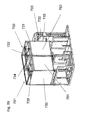
- An embodiment of the apparatus is shown schematically in Fig. 52 .
- the arrangement of all modules of the apparatus facilitates loading of consumables into the apparatus by the user.
- the apparatus and the individual modules are also more easily accessible for servicing than existing analytical apparatuses.
- the arrangement of the transport module along the same axis as the modules also allows an optimization of the footprint of the entire apparatus and system because the transport module is used for loading of consumables into the apparatus as well as for transfer of consumables between the different modules and the waste holder.
- An automated method for isolating and analyzing at least one analyte is, furthermore, disclosed, comprising the steps of
- distributing as used herein relates to the aspiration of sample from a sample container, and subsequent dispensing into receptacles for holding a liquid. Preferred embodiments of said container are described hereinafter and hereinbefore, with reference to the preferred embodiments of the analytical apparatus.
- said analyte is transported by the transport module from said second module for isolating the analyte to said third module for analyzing an analyte.
- the isolated analyte is transferred from said first consumable for isolating an analyte comprised in said sample to a second consumable for analyzing said analyte.
- Preferred embodiments of said second consumable are described hereinafter.
- the automated method further comprises a preferred embodiment wherein said second consumable for analyzing said analyte is transferred by the transfer module from the second module for isolating the analyte to the third module for analyzing an analyte.
- the transfer module comprises at least two transfer devices (500), wherein one transfer device transfers consumables from the consumable holder to module (i) or (ii), from module (i) to module (ii) and from module (ii) to an interface between module (ii) and module (iii), and from module (i), module (ii) or the interface to a waste consumable holder; and the second transfer device transfers consumables between the interface and module (iii).
- the transfer module comprises two transfer devices.
- said method additionally comprises, between steps e) and f), the step of preparing reaction mixtures for analyzing said at least one analyte.
- a method and system of isolating and analyzing an analyte in an automated analyzer comprising the steps of providing a liquid sample comprising said analyte to a processing vessel in a module of a first type; transferring said liquid sample comprising said analyte to a module of a second type; isolating and purifying said analyte in said processing vessel in said module of a second type; transferring said purified analyte to a module of a third type; analyzing said analyte in said module of a third type by reacting said analyte with reagents necessary to obtain a detectable signal.
- the timing for transfer and processing within any one module of one type is pre-defined, and said timing in any one module of one type is identical for any one analyte which is isolated and analyzed. Furthermore, the timing of any one type of module can be independent of the timing of any other type of module. Thus, the modules can work autonomously.
- the advantage of the method and system is that the pre-defined timing of any one module one type allows for optimization of the overall workflow timing, and makes it possible to achieve an optimized high throughput for analytical tests.
- the pre-defined timing of the modules makes it possible to start the analytical process, beginning with distribution of samples, only if, at the end of the workflow of one module, a subsequent type of module for the next step in the analytical process is available.
- the isolation and purification of the analyte is only started if, at the end of the isolation and purification process, a module for analyzing the isolated and purified analyte is available.
- said analyzer comprises at least two modules of a third type.
- an first analyte is isolated and analyzed in said automated analyzer, and a second analyte isolated and analyzed in said automated analyzer, wherein said first and second analyte are isolated and analyzed in parallel, wherein said first analyte is analyzed in one of said modules of a third type, and said second analyte is analyzed in a second one of said modules of a third type, and wherein the time for isolating and analyzing said first and second analyte are identical.
- the timing of the analytical tests run in parallel can be kept identical such that any analyte is processed and analyzed in the analytical apparatus under identical conditions.
- This also makes it possible to use more than one module of one type in the automated analyzer while ensuring identical conditions for every test.
- the possibility to use multiple modules of one type makes it possible to adapt the throughput of the analytical apparatus to the needs of the user.
- said analyte is a nucleic acid analyte.
- the analyte is an antibody, or an antigen, or a cell.
- said module of a third type is an amplification module.
- said automated analyzer comprises at least two modules of a second type.
- said analyzer comprises at least four modules of a third type.
- samples comprising at least one analytes are isolated and purified in parallel. More preferably, said samples are isolated and purified in 96 well plates in parallel. Most preferably, the samples are analyzed in 96 well plates in at least one module of a third type.
- At least 192 samples comprising at least one analyte are isolated and purified in parallel in at least two separate modules of a second type, and are analyzed in at least two separate modules of a third type.
- the time for processing within any one of the modules of a second type is identical, and the time for processing within any one of the modules of a third type is identical.
- Preferred embodiments for modules of a first type are sample cells for distributing a sample comprising an analyte to a processing vessel. Sample cells and processing vessels are further described hereinafter.
- modules of a third type are analytical modules, more preferably cells for amplifying an analyte which is a target nucleic acid.
- Preferred embodiments of such cells include temperature controlled incubators, more preferably thermal cyclers.
- a maximum throughput can be obtained by using a setup as shown in Fig. 53 c) by using twice the amount of modules of a third type than modules of a second type.
- said workflow additionally comprises, for the module of a second type, the loading of reagents.
- the transferring in the transfer system is manual or automated. Preferably, the transfer is automated.
- the transfer system transfers consumables and certain reagents between modules and storage areas. Preferred embodiments of storage areas are described below.
- a further preferred storage area is a fridge.
- the apparatus used in the method hereinbefore described preferably comprises a linear transfer module. In another embodiment, it preferably comprises a rotational transfer module.
- the timing of the transfer system which connects the modules is not critical. This means that manual operations on the system during the process, such as loading with consumables, or loading of samples into any one of the modules, do not affect the workflow of the overall system. Also, pauses between two types of modules are, thus, possible without affecting the workflow in the critical processes (those in modules of a first type, of a second type and of a third type).
- the time for isolating and purifying and analyzing any one analyte is identical to the time for isolating and purifying and analyzing any other analyte.
- the process of providing and isolating and purifying at least one analyte is started conditional on the availability of a module of a third type when the process of isolating and purifying and preparing of reaction mixtures is terminated.
- the method and system hereinbefore described may additionally also comprise a module of a fourth type for preparing reactions for analysis in the module of a third type; and a module of a fifth type for detecting a reaction performed in said module of a third type.
- analysis of an analyte comprises both reaction and detection in said module of a third type.
Landscapes
- Health & Medical Sciences (AREA)
- Immunology (AREA)
- Physics & Mathematics (AREA)
- Life Sciences & Earth Sciences (AREA)
- Chemical & Material Sciences (AREA)
- Analytical Chemistry (AREA)
- Biochemistry (AREA)
- General Health & Medical Sciences (AREA)
- General Physics & Mathematics (AREA)
- Pathology (AREA)
- Engineering & Computer Science (AREA)
- Robotics (AREA)
- Automatic Analysis And Handling Materials Therefor (AREA)
- Apparatus Associated With Microorganisms And Enzymes (AREA)
Priority Applications (1)
| Application Number | Priority Date | Filing Date | Title |
|---|---|---|---|
| EP10194263.9A EP2333558B1 (de) | 2009-12-10 | 2010-12-09 | Formverriegelungsgreifsystem |
Applications Claiming Priority (2)
| Application Number | Priority Date | Filing Date | Title |
|---|---|---|---|
| EP09178724 | 2009-12-10 | ||
| EP10194263.9A EP2333558B1 (de) | 2009-12-10 | 2010-12-09 | Formverriegelungsgreifsystem |
Publications (2)
| Publication Number | Publication Date |
|---|---|
| EP2333558A1 true EP2333558A1 (de) | 2011-06-15 |
| EP2333558B1 EP2333558B1 (de) | 2019-01-16 |
Family
ID=42104476
Family Applications (1)
| Application Number | Title | Priority Date | Filing Date |
|---|---|---|---|
| EP10194263.9A Active EP2333558B1 (de) | 2009-12-10 | 2010-12-09 | Formverriegelungsgreifsystem |
Country Status (3)
| Country | Link |
|---|---|
| US (2) | US20110306052A1 (de) |
| EP (1) | EP2333558B1 (de) |
| JP (1) | JP5933918B2 (de) |
Cited By (5)
| Publication number | Priority date | Publication date | Assignee | Title |
|---|---|---|---|---|
| CN103675315A (zh) * | 2013-12-20 | 2014-03-26 | 深圳徳夏生物医学工程有限公司 | 微孔板加样及转运装置 |
| CN106443040A (zh) * | 2016-08-31 | 2017-02-22 | 盐城拜明生物技术有限公司 | 适用于自动化免疫分析仪器的板间移液装置 |
| WO2022223932A1 (fr) * | 2021-04-22 | 2022-10-27 | Arteion | Système de traitement d'échantillons biologiques comprenant un système de convoyage de supports pour récipients d'échantillons biologiques |
| CN115414984A (zh) * | 2022-09-14 | 2022-12-02 | 光子集成(温州)创新研究院 | 一种可机械自锁的试管架托盘装置 |
| RU2852522C1 (ru) * | 2021-04-22 | 2025-12-09 | Артеион | Система для обработки биологических образцов, содержащая систему для перемещения держателей для контейнеров биологических образцов |
Families Citing this family (8)
| Publication number | Priority date | Publication date | Assignee | Title |
|---|---|---|---|---|
| JP5819617B2 (ja) * | 2010-03-04 | 2015-11-24 | エフ.ホフマン−ラ ロシュ アーゲーF. Hoffmann−La Roche Aktiengesellschaft | 分析器のハードウェア構成 |
| DE202013003390U1 (de) * | 2013-04-11 | 2014-07-14 | Brand Gmbh + Co Kg | Pipettiervorrichtung mit einer Mikrodosiereinheit |
| USD854185S1 (en) | 2017-02-03 | 2019-07-16 | Biotix, Inc. | Pipette tip receptacle plate |
| EP3576883A1 (de) * | 2017-02-03 | 2019-12-11 | Biotix, Inc. | Effizient eingenistete pipettenspitzenarrays und zugehörige verfahren |
| CN112384809B (zh) * | 2018-04-07 | 2025-09-23 | 路玛赛特有限责任公司 | 流体自动采样器和培育器 |
| JP7404972B2 (ja) * | 2020-03-30 | 2023-12-26 | 東ソー株式会社 | 試薬容器供給ユニット及びそれを備えた自動分析装置 |
| CN113943634A (zh) * | 2021-11-10 | 2022-01-18 | 美东汇成生命科技(昆山)有限公司 | 一种多功能pcr 96板 |
| WO2025140140A1 (zh) * | 2023-12-29 | 2025-07-03 | 深圳迈瑞生物医疗电子股份有限公司 | 样本检测装置及提取件 |
Citations (10)
| Publication number | Priority date | Publication date | Assignee | Title |
|---|---|---|---|---|
| US5260872A (en) * | 1991-10-04 | 1993-11-09 | Abbott Laboratories | Automated testing system |
| US20020098117A1 (en) * | 1998-05-01 | 2002-07-25 | Gen-Probe Incorporated | Incubator for use in an automated diagnostic analyzer |
| US6458324B1 (en) * | 1998-11-17 | 2002-10-01 | Tecan Trading Ag | Receiving device and receiving means, transfer device, and workstation and method for their operation |
| US20030059823A1 (en) * | 2001-09-21 | 2003-03-27 | Juki Corporation | Hybridization apparatus and method for detecting nucleic acid in sample using the same |
| US6586255B1 (en) * | 1997-07-21 | 2003-07-01 | Quest Diagnostics Incorporated | Automated centrifuge loading device |
| US6846456B2 (en) | 1997-11-14 | 2005-01-25 | Gen-Probe Incorporated | Assay work station |
| US20050226771A1 (en) * | 2003-09-19 | 2005-10-13 | Lehto Dennis A | High speed microplate transfer |
| US20060263270A1 (en) * | 2005-05-18 | 2006-11-23 | Beckman Coulter, Inc. | Robotic grip and twist assembly |
| US20070258858A1 (en) * | 2006-05-03 | 2007-11-08 | Brian Rasnow | Robotic gripper for transporting multiple object types |
| US20090117004A1 (en) * | 2007-11-06 | 2009-05-07 | Abbott Laboratories | System for automatically loading immunoassay analyzer |
Family Cites Families (26)
| Publication number | Priority date | Publication date | Assignee | Title |
|---|---|---|---|---|
| US6159368A (en) * | 1998-10-29 | 2000-12-12 | The Perkin-Elmer Corporation | Multi-well microfiltration apparatus |
| US20020009394A1 (en) * | 1999-04-02 | 2002-01-24 | Hubert Koster | Automated process line |
| JP4141608B2 (ja) * | 2000-01-17 | 2008-08-27 | プレシジョン・システム・サイエンス株式会社 | 容器搬送処理システム |
| US6746648B1 (en) * | 2000-06-15 | 2004-06-08 | Beckman Coulter, Inc. | Method and system for transporting and storing multiple reagent packs and reagent packs used therein |
| DE10140499B4 (de) * | 2001-08-17 | 2005-02-03 | Bruker Daltonik Gmbh | Probenträgerplatten für Massenspektrometrie mit Ionisierung durch matrixunterstützte Laserdesorption |
| JP2003093038A (ja) * | 2001-09-21 | 2003-04-02 | Juki Corp | ハイブリダイゼーション装置及びこれを用いたサンプル中の核酸検出方法 |
| JP3924595B2 (ja) * | 2001-12-07 | 2007-06-06 | 株式会社アステム | マルチウェルプレート搬送装置 |
| US7867444B2 (en) * | 2002-05-30 | 2011-01-11 | Siemens Healthcare Diagnostics, Inc. | Lab cell centrifuging module |
| JP2007263972A (ja) * | 2002-10-10 | 2007-10-11 | Matsushita Electric Ind Co Ltd | 情報提示方法および情報提示装置 |
| US20070184548A1 (en) * | 2002-12-23 | 2007-08-09 | Lim Hi Tan | Device for carrying out chemical or biological reactions |
| JP4737976B2 (ja) * | 2004-03-31 | 2011-08-03 | ベクトン・ディキンソン・アンド・カンパニー | ロボットハンドリング用のマイクロプレートおよびふた |
| JP2006010484A (ja) * | 2004-06-25 | 2006-01-12 | Hitachi Koki Co Ltd | 自動分注装置 |
| JP4196923B2 (ja) * | 2004-10-05 | 2008-12-17 | パナソニック株式会社 | 液体分注ヘッド装置及び液体分注装置 |
| AU2006214085A1 (en) * | 2005-02-18 | 2006-08-24 | Canon U.S. Life Sciences, Inc. | Devices and methods for identifying genomic DNA of organisms |
| WO2007021820A2 (en) * | 2005-08-11 | 2007-02-22 | Eksigent Technologies, Llc | Methods for measuring biochemical reactions |
| US7876935B2 (en) * | 2006-01-30 | 2011-01-25 | Protedyne Corporation | Sample processing apparatus with a vision system |
| JP2009534688A (ja) * | 2006-04-24 | 2009-09-24 | プロテダイン・コーポレーション | 自律的に作動するツールを備えているロボットシステム |
| AU2006345918B2 (en) * | 2006-07-04 | 2013-06-13 | Eppendorf Se | Modular storage system for laboratory fluids |
| US7976217B2 (en) * | 2006-09-15 | 2011-07-12 | Corning Incorporated | Screening system and method for analyzing a plurality of biosensors |
| JP4899981B2 (ja) * | 2007-03-28 | 2012-03-21 | 和光純薬工業株式会社 | マイクロプレートの搬送装置 |
| JP2007263971A (ja) * | 2007-05-25 | 2007-10-11 | Mba:Kk | ナビゲーション装置 |
| JP5100277B2 (ja) * | 2007-09-20 | 2012-12-19 | シスメックス株式会社 | ピペットチップ供給装置および検体分析装置 |
| JP2009079940A (ja) * | 2007-09-25 | 2009-04-16 | Tosoh Corp | ピペットチップの搬送装置 |
| DE102008001288A1 (de) * | 2008-04-21 | 2009-10-22 | Robert Bosch Gmbh | Greifvorrichtung zum Aufnehmen von Behältern und Verschlüssen sowie zum Verschließen der Behälter |
| US8168137B2 (en) * | 2008-06-02 | 2012-05-01 | Agilent Technologies, Inc. | Nestable, stackable pipette rack for nestable pipette tips |
| JP5662124B2 (ja) * | 2009-12-10 | 2015-01-28 | エフ.ホフマン−ラ ロシュ アーゲーF. Hoffmann−La Roche Aktiengesellschaft | 消耗品のハードウェア・コード化システム |
-
2010
- 2010-12-07 JP JP2010272535A patent/JP5933918B2/ja active Active
- 2010-12-08 US US12/963,167 patent/US20110306052A1/en not_active Abandoned
- 2010-12-09 EP EP10194263.9A patent/EP2333558B1/de active Active
-
2014
- 2014-10-07 US US14/508,713 patent/US9958469B2/en active Active
Patent Citations (10)
| Publication number | Priority date | Publication date | Assignee | Title |
|---|---|---|---|---|
| US5260872A (en) * | 1991-10-04 | 1993-11-09 | Abbott Laboratories | Automated testing system |
| US6586255B1 (en) * | 1997-07-21 | 2003-07-01 | Quest Diagnostics Incorporated | Automated centrifuge loading device |
| US6846456B2 (en) | 1997-11-14 | 2005-01-25 | Gen-Probe Incorporated | Assay work station |
| US20020098117A1 (en) * | 1998-05-01 | 2002-07-25 | Gen-Probe Incorporated | Incubator for use in an automated diagnostic analyzer |
| US6458324B1 (en) * | 1998-11-17 | 2002-10-01 | Tecan Trading Ag | Receiving device and receiving means, transfer device, and workstation and method for their operation |
| US20030059823A1 (en) * | 2001-09-21 | 2003-03-27 | Juki Corporation | Hybridization apparatus and method for detecting nucleic acid in sample using the same |
| US20050226771A1 (en) * | 2003-09-19 | 2005-10-13 | Lehto Dennis A | High speed microplate transfer |
| US20060263270A1 (en) * | 2005-05-18 | 2006-11-23 | Beckman Coulter, Inc. | Robotic grip and twist assembly |
| US20070258858A1 (en) * | 2006-05-03 | 2007-11-08 | Brian Rasnow | Robotic gripper for transporting multiple object types |
| US20090117004A1 (en) * | 2007-11-06 | 2009-05-07 | Abbott Laboratories | System for automatically loading immunoassay analyzer |
Cited By (8)
| Publication number | Priority date | Publication date | Assignee | Title |
|---|---|---|---|---|
| CN103675315A (zh) * | 2013-12-20 | 2014-03-26 | 深圳徳夏生物医学工程有限公司 | 微孔板加样及转运装置 |
| CN103675315B (zh) * | 2013-12-20 | 2015-12-16 | 深圳徳夏生物医学工程有限公司 | 微孔板加样及转运装置 |
| CN106443040A (zh) * | 2016-08-31 | 2017-02-22 | 盐城拜明生物技术有限公司 | 适用于自动化免疫分析仪器的板间移液装置 |
| CN106443040B (zh) * | 2016-08-31 | 2018-02-13 | 江苏拜明生物技术有限公司 | 适用于自动化免疫分析仪器的板间移液装置 |
| WO2022223932A1 (fr) * | 2021-04-22 | 2022-10-27 | Arteion | Système de traitement d'échantillons biologiques comprenant un système de convoyage de supports pour récipients d'échantillons biologiques |
| FR3122174A1 (fr) * | 2021-04-22 | 2022-10-28 | Arteion | Système de convoyage de supports pour récipients d’échantillons biologiques, et système de traitement d’échantillons biologiques comprenant un tel système de convoyage |
| RU2852522C1 (ru) * | 2021-04-22 | 2025-12-09 | Артеион | Система для обработки биологических образцов, содержащая систему для перемещения держателей для контейнеров биологических образцов |
| CN115414984A (zh) * | 2022-09-14 | 2022-12-02 | 光子集成(温州)创新研究院 | 一种可机械自锁的试管架托盘装置 |
Also Published As
| Publication number | Publication date |
|---|---|
| US9958469B2 (en) | 2018-05-01 |
| JP2011123068A (ja) | 2011-06-23 |
| EP2333558B1 (de) | 2019-01-16 |
| US20110306052A1 (en) | 2011-12-15 |
| JP5933918B2 (ja) | 2016-06-15 |
| US20160161515A1 (en) | 2016-06-09 |
Similar Documents
| Publication | Publication Date | Title |
|---|---|---|
| US10351843B2 (en) | System for separating and detecting an analyte | |
| CA2724132C (en) | Amplification system with spatial separation | |
| EP2338597B1 (de) | Multiwellplatte und Deckel | |
| EP2338596B1 (de) | Pipettenspitzenträger | |
| US9678092B2 (en) | Workflow timing between modules | |
| US9696327B2 (en) | Consumable hardware coding system | |
| EP2333558B1 (de) | Formverriegelungsgreifsystem | |
| EP2338600A1 (de) | Prozesskopfpositionierung | |
| EP2363713B1 (de) | Hardware-Architektur für Analysiergeräte |
Legal Events
| Date | Code | Title | Description |
|---|---|---|---|
| PUAI | Public reference made under article 153(3) epc to a published international application that has entered the european phase |
Free format text: ORIGINAL CODE: 0009012 |
|
| AK | Designated contracting states |
Kind code of ref document: A1 Designated state(s): AL AT BE BG CH CY CZ DE DK EE ES FI FR GB GR HR HU IE IS IT LI LT LU LV MC MK MT NL NO PL PT RO RS SE SI SK SM TR |
|
| AX | Request for extension of the european patent |
Extension state: BA ME |
|
| 17P | Request for examination filed |
Effective date: 20111215 |
|
| STAA | Information on the status of an ep patent application or granted ep patent |
Free format text: STATUS: EXAMINATION IS IN PROGRESS |
|
| 17Q | First examination report despatched |
Effective date: 20171011 |
|
| GRAP | Despatch of communication of intention to grant a patent |
Free format text: ORIGINAL CODE: EPIDOSNIGR1 |
|
| STAA | Information on the status of an ep patent application or granted ep patent |
Free format text: STATUS: GRANT OF PATENT IS INTENDED |
|
| INTG | Intention to grant announced |
Effective date: 20180306 |
|
| GRAJ | Information related to disapproval of communication of intention to grant by the applicant or resumption of examination proceedings by the epo deleted |
Free format text: ORIGINAL CODE: EPIDOSDIGR1 |
|
| STAA | Information on the status of an ep patent application or granted ep patent |
Free format text: STATUS: EXAMINATION IS IN PROGRESS |
|
| GRAP | Despatch of communication of intention to grant a patent |
Free format text: ORIGINAL CODE: EPIDOSNIGR1 |
|
| STAA | Information on the status of an ep patent application or granted ep patent |
Free format text: STATUS: GRANT OF PATENT IS INTENDED |
|
| INTC | Intention to grant announced (deleted) | ||
| INTG | Intention to grant announced |
Effective date: 20180607 |
|
| RIN1 | Information on inventor provided before grant (corrected) |
Inventor name: THALMANN, CHRISTIAN Inventor name: BELZ, RENATO Inventor name: KNECHT, URS Inventor name: SCHAERER, VERONIKA |
|
| GRAS | Grant fee paid |
Free format text: ORIGINAL CODE: EPIDOSNIGR3 |
|
| GRAA | (expected) grant |
Free format text: ORIGINAL CODE: 0009210 |
|
| STAA | Information on the status of an ep patent application or granted ep patent |
Free format text: STATUS: THE PATENT HAS BEEN GRANTED |
|
| RAP1 | Party data changed (applicant data changed or rights of an application transferred) |
Owner name: ROCHE DIAGNOSTICS GMBH Owner name: F. HOFFMANN-LA ROCHE AG |
|
| AK | Designated contracting states |
Kind code of ref document: B1 Designated state(s): AL AT BE BG CH CY CZ DE DK EE ES FI FR GB GR HR HU IE IS IT LI LT LU LV MC MK MT NL NO PL PT RO RS SE SI SK SM TR |
|
| REG | Reference to a national code |
Ref country code: GB Ref legal event code: FG4D |
|
| REG | Reference to a national code |
Ref country code: CH Ref legal event code: EP |
|
| REG | Reference to a national code |
Ref country code: IE Ref legal event code: FG4D |
|
| REG | Reference to a national code |
Ref country code: DE Ref legal event code: R096 Ref document number: 602010056556 Country of ref document: DE |
|
| REG | Reference to a national code |
Ref country code: AT Ref legal event code: REF Ref document number: 1090091 Country of ref document: AT Kind code of ref document: T Effective date: 20190215 |
|
| REG | Reference to a national code |
Ref country code: NL Ref legal event code: MP Effective date: 20190116 |
|
| REG | Reference to a national code |
Ref country code: LT Ref legal event code: MG4D |
|
| PG25 | Lapsed in a contracting state [announced via postgrant information from national office to epo] |
Ref country code: NL Free format text: LAPSE BECAUSE OF FAILURE TO SUBMIT A TRANSLATION OF THE DESCRIPTION OR TO PAY THE FEE WITHIN THE PRESCRIBED TIME-LIMIT Effective date: 20190116 |
|
| REG | Reference to a national code |
Ref country code: AT Ref legal event code: MK05 Ref document number: 1090091 Country of ref document: AT Kind code of ref document: T Effective date: 20190116 |
|
| PG25 | Lapsed in a contracting state [announced via postgrant information from national office to epo] |
Ref country code: FI Free format text: LAPSE BECAUSE OF FAILURE TO SUBMIT A TRANSLATION OF THE DESCRIPTION OR TO PAY THE FEE WITHIN THE PRESCRIBED TIME-LIMIT Effective date: 20190116 Ref country code: NO Free format text: LAPSE BECAUSE OF FAILURE TO SUBMIT A TRANSLATION OF THE DESCRIPTION OR TO PAY THE FEE WITHIN THE PRESCRIBED TIME-LIMIT Effective date: 20190416 Ref country code: SE Free format text: LAPSE BECAUSE OF FAILURE TO SUBMIT A TRANSLATION OF THE DESCRIPTION OR TO PAY THE FEE WITHIN THE PRESCRIBED TIME-LIMIT Effective date: 20190116 Ref country code: PT Free format text: LAPSE BECAUSE OF FAILURE TO SUBMIT A TRANSLATION OF THE DESCRIPTION OR TO PAY THE FEE WITHIN THE PRESCRIBED TIME-LIMIT Effective date: 20190516 Ref country code: PL Free format text: LAPSE BECAUSE OF FAILURE TO SUBMIT A TRANSLATION OF THE DESCRIPTION OR TO PAY THE FEE WITHIN THE PRESCRIBED TIME-LIMIT Effective date: 20190116 Ref country code: LT Free format text: LAPSE BECAUSE OF FAILURE TO SUBMIT A TRANSLATION OF THE DESCRIPTION OR TO PAY THE FEE WITHIN THE PRESCRIBED TIME-LIMIT Effective date: 20190116 Ref country code: ES Free format text: LAPSE BECAUSE OF FAILURE TO SUBMIT A TRANSLATION OF THE DESCRIPTION OR TO PAY THE FEE WITHIN THE PRESCRIBED TIME-LIMIT Effective date: 20190116 |
|
| PG25 | Lapsed in a contracting state [announced via postgrant information from national office to epo] |
Ref country code: LV Free format text: LAPSE BECAUSE OF FAILURE TO SUBMIT A TRANSLATION OF THE DESCRIPTION OR TO PAY THE FEE WITHIN THE PRESCRIBED TIME-LIMIT Effective date: 20190116 Ref country code: GR Free format text: LAPSE BECAUSE OF FAILURE TO SUBMIT A TRANSLATION OF THE DESCRIPTION OR TO PAY THE FEE WITHIN THE PRESCRIBED TIME-LIMIT Effective date: 20190417 Ref country code: HR Free format text: LAPSE BECAUSE OF FAILURE TO SUBMIT A TRANSLATION OF THE DESCRIPTION OR TO PAY THE FEE WITHIN THE PRESCRIBED TIME-LIMIT Effective date: 20190116 Ref country code: IS Free format text: LAPSE BECAUSE OF FAILURE TO SUBMIT A TRANSLATION OF THE DESCRIPTION OR TO PAY THE FEE WITHIN THE PRESCRIBED TIME-LIMIT Effective date: 20190516 Ref country code: BG Free format text: LAPSE BECAUSE OF FAILURE TO SUBMIT A TRANSLATION OF THE DESCRIPTION OR TO PAY THE FEE WITHIN THE PRESCRIBED TIME-LIMIT Effective date: 20190416 Ref country code: RS Free format text: LAPSE BECAUSE OF FAILURE TO SUBMIT A TRANSLATION OF THE DESCRIPTION OR TO PAY THE FEE WITHIN THE PRESCRIBED TIME-LIMIT Effective date: 20190116 |
|
| REG | Reference to a national code |
Ref country code: DE Ref legal event code: R097 Ref document number: 602010056556 Country of ref document: DE |
|
| PG25 | Lapsed in a contracting state [announced via postgrant information from national office to epo] |
Ref country code: AT Free format text: LAPSE BECAUSE OF FAILURE TO SUBMIT A TRANSLATION OF THE DESCRIPTION OR TO PAY THE FEE WITHIN THE PRESCRIBED TIME-LIMIT Effective date: 20190116 Ref country code: EE Free format text: LAPSE BECAUSE OF FAILURE TO SUBMIT A TRANSLATION OF THE DESCRIPTION OR TO PAY THE FEE WITHIN THE PRESCRIBED TIME-LIMIT Effective date: 20190116 Ref country code: DK Free format text: LAPSE BECAUSE OF FAILURE TO SUBMIT A TRANSLATION OF THE DESCRIPTION OR TO PAY THE FEE WITHIN THE PRESCRIBED TIME-LIMIT Effective date: 20190116 Ref country code: RO Free format text: LAPSE BECAUSE OF FAILURE TO SUBMIT A TRANSLATION OF THE DESCRIPTION OR TO PAY THE FEE WITHIN THE PRESCRIBED TIME-LIMIT Effective date: 20190116 Ref country code: CZ Free format text: LAPSE BECAUSE OF FAILURE TO SUBMIT A TRANSLATION OF THE DESCRIPTION OR TO PAY THE FEE WITHIN THE PRESCRIBED TIME-LIMIT Effective date: 20190116 Ref country code: IT Free format text: LAPSE BECAUSE OF FAILURE TO SUBMIT A TRANSLATION OF THE DESCRIPTION OR TO PAY THE FEE WITHIN THE PRESCRIBED TIME-LIMIT Effective date: 20190116 Ref country code: SK Free format text: LAPSE BECAUSE OF FAILURE TO SUBMIT A TRANSLATION OF THE DESCRIPTION OR TO PAY THE FEE WITHIN THE PRESCRIBED TIME-LIMIT Effective date: 20190116 Ref country code: AL Free format text: LAPSE BECAUSE OF FAILURE TO SUBMIT A TRANSLATION OF THE DESCRIPTION OR TO PAY THE FEE WITHIN THE PRESCRIBED TIME-LIMIT Effective date: 20190116 |
|
| PLBE | No opposition filed within time limit |
Free format text: ORIGINAL CODE: 0009261 |
|
| STAA | Information on the status of an ep patent application or granted ep patent |
Free format text: STATUS: NO OPPOSITION FILED WITHIN TIME LIMIT |
|
| PG25 | Lapsed in a contracting state [announced via postgrant information from national office to epo] |
Ref country code: SM Free format text: LAPSE BECAUSE OF FAILURE TO SUBMIT A TRANSLATION OF THE DESCRIPTION OR TO PAY THE FEE WITHIN THE PRESCRIBED TIME-LIMIT Effective date: 20190116 |
|
| 26N | No opposition filed |
Effective date: 20191017 |
|
| PG25 | Lapsed in a contracting state [announced via postgrant information from national office to epo] |
Ref country code: SI Free format text: LAPSE BECAUSE OF FAILURE TO SUBMIT A TRANSLATION OF THE DESCRIPTION OR TO PAY THE FEE WITHIN THE PRESCRIBED TIME-LIMIT Effective date: 20190116 |
|
| PG25 | Lapsed in a contracting state [announced via postgrant information from national office to epo] |
Ref country code: TR Free format text: LAPSE BECAUSE OF FAILURE TO SUBMIT A TRANSLATION OF THE DESCRIPTION OR TO PAY THE FEE WITHIN THE PRESCRIBED TIME-LIMIT Effective date: 20190116 |
|
| REG | Reference to a national code |
Ref country code: BE Ref legal event code: MM Effective date: 20191231 |
|
| PG25 | Lapsed in a contracting state [announced via postgrant information from national office to epo] |
Ref country code: MC Free format text: LAPSE BECAUSE OF FAILURE TO SUBMIT A TRANSLATION OF THE DESCRIPTION OR TO PAY THE FEE WITHIN THE PRESCRIBED TIME-LIMIT Effective date: 20190116 |
|
| PG25 | Lapsed in a contracting state [announced via postgrant information from national office to epo] |
Ref country code: IE Free format text: LAPSE BECAUSE OF NON-PAYMENT OF DUE FEES Effective date: 20191209 Ref country code: LU Free format text: LAPSE BECAUSE OF NON-PAYMENT OF DUE FEES Effective date: 20191209 |
|
| PG25 | Lapsed in a contracting state [announced via postgrant information from national office to epo] |
Ref country code: BE Free format text: LAPSE BECAUSE OF NON-PAYMENT OF DUE FEES Effective date: 20191231 |
|
| PG25 | Lapsed in a contracting state [announced via postgrant information from national office to epo] |
Ref country code: CY Free format text: LAPSE BECAUSE OF FAILURE TO SUBMIT A TRANSLATION OF THE DESCRIPTION OR TO PAY THE FEE WITHIN THE PRESCRIBED TIME-LIMIT Effective date: 20190116 |
|
| PG25 | Lapsed in a contracting state [announced via postgrant information from national office to epo] |
Ref country code: MT Free format text: LAPSE BECAUSE OF FAILURE TO SUBMIT A TRANSLATION OF THE DESCRIPTION OR TO PAY THE FEE WITHIN THE PRESCRIBED TIME-LIMIT Effective date: 20190116 Ref country code: HU Free format text: LAPSE BECAUSE OF FAILURE TO SUBMIT A TRANSLATION OF THE DESCRIPTION OR TO PAY THE FEE WITHIN THE PRESCRIBED TIME-LIMIT; INVALID AB INITIO Effective date: 20101209 |
|
| PG25 | Lapsed in a contracting state [announced via postgrant information from national office to epo] |
Ref country code: MK Free format text: LAPSE BECAUSE OF FAILURE TO SUBMIT A TRANSLATION OF THE DESCRIPTION OR TO PAY THE FEE WITHIN THE PRESCRIBED TIME-LIMIT Effective date: 20190116 |
|
| REG | Reference to a national code |
Ref country code: CH Ref legal event code: U11 Free format text: ST27 STATUS EVENT CODE: U-0-0-U10-U11 (AS PROVIDED BY THE NATIONAL OFFICE) Effective date: 20260101 |
|
| PGFP | Annual fee paid to national office [announced via postgrant information from national office to epo] |
Ref country code: DE Payment date: 20251126 Year of fee payment: 16 |
|
| PGFP | Annual fee paid to national office [announced via postgrant information from national office to epo] |
Ref country code: GB Payment date: 20251119 Year of fee payment: 16 |
|
| PGFP | Annual fee paid to national office [announced via postgrant information from national office to epo] |
Ref country code: FR Payment date: 20251119 Year of fee payment: 16 |
|
| PGFP | Annual fee paid to national office [announced via postgrant information from national office to epo] |
Ref country code: CH Payment date: 20260101 Year of fee payment: 16 |