EP2333577A2 - Procédés et systèmes permettant de définir un VOI dans un espace d'imagerie ultrasonore - Google Patents
Procédés et systèmes permettant de définir un VOI dans un espace d'imagerie ultrasonore Download PDFInfo
- Publication number
- EP2333577A2 EP2333577A2 EP10015053A EP10015053A EP2333577A2 EP 2333577 A2 EP2333577 A2 EP 2333577A2 EP 10015053 A EP10015053 A EP 10015053A EP 10015053 A EP10015053 A EP 10015053A EP 2333577 A2 EP2333577 A2 EP 2333577A2
- Authority
- EP
- European Patent Office
- Prior art keywords
- points
- reference point
- projection
- voi
- proxy
- Prior art date
- Legal status (The legal status is an assumption and is not a legal conclusion. Google has not performed a legal analysis and makes no representation as to the accuracy of the status listed.)
- Granted
Links
Images





Classifications
-
- G—PHYSICS
- G06—COMPUTING OR CALCULATING; COUNTING
- G06T—IMAGE DATA PROCESSING OR GENERATION, IN GENERAL
- G06T19/00—Manipulating three-dimensional [3D] models or images for computer graphics
-
- G—PHYSICS
- G01—MEASURING; TESTING
- G01S—RADIO DIRECTION-FINDING; RADIO NAVIGATION; DETERMINING DISTANCE OR VELOCITY BY USE OF RADIO WAVES; LOCATING OR PRESENCE-DETECTING BY USE OF THE REFLECTION OR RERADIATION OF RADIO WAVES; ANALOGOUS ARRANGEMENTS USING OTHER WAVES
- G01S7/00—Details of systems according to groups G01S13/00, G01S15/00, G01S17/00
- G01S7/52—Details of systems according to groups G01S13/00, G01S15/00, G01S17/00 of systems according to group G01S15/00
- G01S7/52017—Details of systems according to groups G01S13/00, G01S15/00, G01S17/00 of systems according to group G01S15/00 particularly adapted to short-range imaging
- G01S7/52053—Display arrangements
- G01S7/52057—Cathode ray tube displays
- G01S7/5206—Two-dimensional coordinated display of distance and direction; B-scan display
- G01S7/52063—Sector scan display
-
- G—PHYSICS
- G06—COMPUTING OR CALCULATING; COUNTING
- G06F—ELECTRIC DIGITAL DATA PROCESSING
- G06F18/00—Pattern recognition
- G06F18/20—Analysing
- G06F18/21—Design or setup of recognition systems or techniques; Extraction of features in feature space; Blind source separation
- G06F18/2163—Partitioning the feature space
-
- G—PHYSICS
- G06—COMPUTING OR CALCULATING; COUNTING
- G06T—IMAGE DATA PROCESSING OR GENERATION, IN GENERAL
- G06T7/00—Image analysis
- G06T7/10—Segmentation; Edge detection
- G06T7/11—Region-based segmentation
-
- G—PHYSICS
- G06—COMPUTING OR CALCULATING; COUNTING
- G06T—IMAGE DATA PROCESSING OR GENERATION, IN GENERAL
- G06T7/00—Image analysis
- G06T7/60—Analysis of geometric attributes
-
- A—HUMAN NECESSITIES
- A61—MEDICAL OR VETERINARY SCIENCE; HYGIENE
- A61B—DIAGNOSIS; SURGERY; IDENTIFICATION
- A61B8/00—Diagnosis using ultrasonic, sonic or infrasonic waves
- A61B8/46—Ultrasonic, sonic or infrasonic diagnostic devices with special arrangements for interfacing with the operator or the patient
- A61B8/461—Displaying means of special interest
- A61B8/466—Displaying means of special interest adapted to display 3D data
-
- A—HUMAN NECESSITIES
- A61—MEDICAL OR VETERINARY SCIENCE; HYGIENE
- A61B—DIAGNOSIS; SURGERY; IDENTIFICATION
- A61B8/00—Diagnosis using ultrasonic, sonic or infrasonic waves
- A61B8/46—Ultrasonic, sonic or infrasonic diagnostic devices with special arrangements for interfacing with the operator or the patient
- A61B8/467—Ultrasonic, sonic or infrasonic diagnostic devices with special arrangements for interfacing with the operator or the patient characterised by special input means
- A61B8/469—Ultrasonic, sonic or infrasonic diagnostic devices with special arrangements for interfacing with the operator or the patient characterised by special input means for selection of a region of interest
-
- A—HUMAN NECESSITIES
- A61—MEDICAL OR VETERINARY SCIENCE; HYGIENE
- A61B—DIAGNOSIS; SURGERY; IDENTIFICATION
- A61B8/00—Diagnosis using ultrasonic, sonic or infrasonic waves
- A61B8/48—Diagnostic techniques
- A61B8/483—Diagnostic techniques involving the acquisition of a 3D volume of data
-
- G—PHYSICS
- G01—MEASURING; TESTING
- G01S—RADIO DIRECTION-FINDING; RADIO NAVIGATION; DETERMINING DISTANCE OR VELOCITY BY USE OF RADIO WAVES; LOCATING OR PRESENCE-DETECTING BY USE OF THE REFLECTION OR RERADIATION OF RADIO WAVES; ANALOGOUS ARRANGEMENTS USING OTHER WAVES
- G01S15/00—Systems using the reflection or reradiation of acoustic waves, e.g. sonar systems
- G01S15/88—Sonar systems specially adapted for specific applications
- G01S15/89—Sonar systems specially adapted for specific applications for mapping or imaging
- G01S15/8906—Short-range imaging systems; Acoustic microscope systems using pulse-echo techniques
- G01S15/8993—Three dimensional imaging systems
-
- G—PHYSICS
- G06—COMPUTING OR CALCULATING; COUNTING
- G06T—IMAGE DATA PROCESSING OR GENERATION, IN GENERAL
- G06T2207/00—Indexing scheme for image analysis or image enhancement
- G06T2207/10—Image acquisition modality
- G06T2207/10132—Ultrasound image
-
- G—PHYSICS
- G06—COMPUTING OR CALCULATING; COUNTING
- G06T—IMAGE DATA PROCESSING OR GENERATION, IN GENERAL
- G06T2207/00—Indexing scheme for image analysis or image enhancement
- G06T2207/20—Special algorithmic details
- G06T2207/20092—Interactive image processing based on input by user
- G06T2207/20104—Interactive definition of region of interest [ROI]
-
- G—PHYSICS
- G06—COMPUTING OR CALCULATING; COUNTING
- G06T—IMAGE DATA PROCESSING OR GENERATION, IN GENERAL
- G06T2207/00—Indexing scheme for image analysis or image enhancement
- G06T2207/30—Subject of image; Context of image processing
- G06T2207/30004—Biomedical image processing
-
- G—PHYSICS
- G06—COMPUTING OR CALCULATING; COUNTING
- G06T—IMAGE DATA PROCESSING OR GENERATION, IN GENERAL
- G06T2219/00—Indexing scheme for manipulating 3D models or images for computer graphics
- G06T2219/008—Cut plane or projection plane definition
Definitions
- the following disclosure relates generally to three-dimensional (3D) ultrasound imaging systems, and more particularly to methods and systems for defining a volume of interest (VOI) in an ultrasound imaging space.
- 3D three-dimensional
- VOI volume of interest
- Ultrasound imaging devices are widely used because they are non-destructive, radiationless, and highly flexible in operation.
- Conventional ultrasound imaging devices provide only two-dimensional images of the human body. Therefore, the sizes and shapes of lesions can only be empirically estimated by doctors based on a plurality of two-dimensional images, and the three-dimensional geometry of a lesions and its surrounding tissues must be imagined by the doctor. This leads to difficulties in diagnosis.
- 3D visualization technology in ultrasound imaging systems, diagnosis has become more convenient. For example, a 3D image may be reconstructed base on a series of two-dimensional images and then may be displayed on a monitor. Not only the overall visual construction of the imaging object may be obtained from the 3D image, but also a lot of important 3D information may be saved. As a result, 3D ultrasound imaging devices have been widely used in clinical practice in recent years.
- the 3D ultrasound imaging process usually includes three steps: data acquisition, reconstruction and rendering.
- 3D ultrasound volume data are collected in the data acquisition step.
- the reconstruction step the collected volume data are converted to corresponding volume data in Cartesian coordinates.
- the relative position of the volume data in Cartesian coordinates must be consistent with the real space position of the volume data.
- the rendering step the volume data are calculated using a visualization algorithm to obtain visual data, after which the visual data are displayed on a monitor.
- 3D ultrasound systems typically use VOI (volume of interest) technology.
- the VOI represents a user-configurable geometric figure in three-dimensional space. Using the VOI in 3D rendering, only the volume data inside the geometric figure are used to produce a 3D image.
- the volume data in which users are interested are defined as the target, while the other data are defined as the background. If the users can make the target into the VOI, then only the 3D image of the target is obtained and displayed.
- VOI technology facilitates target observation.
- Traditional VOI is preset as a rectangular parallelepiped that includes 6 flat surfaces. This can easily lead to ineffectiveness of separating the target and the background when the target profile is complicated. If at least one of the flat surfaces is replaced by a "curved" surface, it is referred to as a curved surface VOI.
- the curved surface VOI greatly increases the flexibility of the VOI setting, making it easier for users to separate the target and background based on objective conditions or subjective personal ideas.
- U.S. Patent 7,433,504 discloses a method for defining a volume of interest in a medical image. According to this method, a user interface is used to select a point on an initial linear border segment of a VOI. The user then moves the point from its initial position on the linear border segment to a new position and a processor then forms a new, non-linear border segment that includes the point. A 3-D presentation of the VOI is then created.
- An ultrasound imaging system provides method for defining a VOI in an ultrasound imaging space.
- the system defines an initial frame of a VOI in ultrasound imaging space, receives a selection of at least one reference point at an arbitrary location in the ultrasound imaging space, creates at least one curved surface using at least one element of the initial frame and the at least one reference point, and then creates the VOI based on the curved surface in the ultrasound imaging space.
- FIG. 1 is a block diagram of an embodiment of a 3D ultrasound imaging system
- FIG. 2 is a flow-chart illustrating a 3D imaging process according to the 3D ultrasound imaging system of FIG. 1 ;
- FIG. 3 is a flow diagram of an embodiment of a method for defining a VOl
- FIG. 4 is a schematic diagram of an embodiment of a initial frame of a VOI
- FIG. 5 is a schematic diagram illustrating an embodiment of generating a curved surface of a VOI base on the initial frame and the reference point;
- FIG. 6 is a schematic diagram of an embodiment of a generated curved surface of a VOI
- FIG. 7 is a schematic diagram of another embodiment of a generated curved surface of a VOI
- FIG. 8 is a schematic diagram of an embodiment of a plurality of reference points
- FIG. 9 is a schematic diagram of an embodiment of a display interface of a 3D ultrasound imaging system.
- FIG. 10 is a flow diagram of another embodiment of a method of defining a VOI
- FIG. 11 is a schematic diagram illustrating an embodiment of calculating the reverse projection point of a proxy reference point
- FIG. 12 is a block diagram of an embodiment of an apparatus for defining a VOI
- FIG. 13 is a block diagram of another embodiment of an apparatus for defining a VOI.
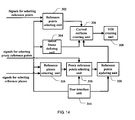
- FIG. 14 is a block diagram of a further embodiment of an apparatus for defining a VOI.
- a 3D ultrasound imaging system includes a probe 2, a transmitting/receiving switch 3, a transmitting circuit 4, a receiving circuit 5, a beam-forming module 6, a signal processing module 7, a 3D imaging module 8, and a monitor 9.
- the transmitting circuit 4 sends a group of pulses which have been focused with time delays to the probe 2.
- the probe 2 emits ultrasound waves to the tissues to be imaged (not shown), then receives ultrasound echoes reflected from the tissues which carrying tissue information, and converts the ultrasound echoes to electrical signals.
- the receiving circuit 5 receives these electrical signals and transmits them to the beam-forming module 6. After time delay focusing, weighting and channel summation processing, those signals are transmitted to the signal processing module 7 for signal processing. Thereafter, the signals are sent to the 3D imaging module 8 for 3D imaging processing. Finally, the 3D images with other visual information are transmitted to the monitor 9 for display.
- a processing procedure of the 3D imaging module 8 includes three steps: acquisition, reconstruction and rendering.
- acquisition step the original 3D ultrasound volume data are obtained.
- the original volume data are converted into reconstructed volume data in some chosen coordinate system, such as rectangular, Cartesian coordinates, which have relative positions corresponding to that of the real space.
- some chosen coordinate system such as rectangular, Cartesian coordinates, which have relative positions corresponding to that of the real space.
- the reconstructed volume data are processed with a visual algorithm to obtain visual information (e.g., 3D images), and the visual information is displayed on a monitor.
- visual information e.g., 3D images
- the original volume data are acquired in the acquisition step, then the original volume data are converted into reconstructed volume data in the reconstruction step, and the reconstructed volume data are calculated and processed with possible user's interaction to obtain the visual information.
- the entire space region is scanned including the imaging target to obtain the information about the tissue or other targets (organs, blood, etc.) in the target space region.
- the space region is referred to herein as the "ultrasound imaging space”.
- 3D ultrasound systems use VOI technology.
- VOI geometric figure
- a geometric figure is defined in the ultrasound imaging space.
- the 3D rendering step only the volume data which are contained in this geometric figure (VOI) will be rendered in conventional systems.
- a method for defining a VOI includes an initial frame definition step 102, a reference point selection step 104, a VOI curved surface generation step 106, and a VOI creation step 108.
- the VOI may be defined without showing the ultrasound images.
- the VOI can also be adjustable for users, and users' interactions may be included in the process of defining the VOI. Therefore, it is feasible to display the ultrasound image, and define the VOI, according to the displayed ultrasound image. As a result, it is possible to see whether the desired 3D imaging target is included in the defined VOI. Certain embodiments may also include steps of displaying ultrasound images.
- an initial frame of the VOI is defined in the ultrasound imaging space as the basis of the final VOI.
- the initial frame may be one of the common geometric figures, such as cuboid, cube, cylinder, etc., and could be chosen based on actual needs, taking into account such factors like convenience of subsequent calculations.
- Setting of the initial frame, including its shape, size, location in the image, etc. may be set with default settings during the initialization of the 3D ultrasound imaging system, and may also be set by the user through a user interface.
- the set initial frame may also be adjusted by the user through the user interface or automatically by the 3D ultrasound imaging system.
- the set initial frame may include the whole 3D imaging target, part of the 3D imaging target, or even exclude the 3D imaging target.
- the initial frame is set to be a cuboid as shown in FIG. 4 .
- the 3D imaging target 20 is not totally contained in the initial frame 10.
- the reference point selection step 104 at least one reference point is selected from the ultrasound imaging space according to a received reference point selecting signal.
- the location of this reference point may be anywhere in the ultrasound imaging space, including the inside of the initial frame or outside of the initial frame.
- T he reference point selecting signal may be a default setting from the 3D ultrasound imaging system, which gives the 3D coordinates of the reference point(s) directly. Alternatively, it may be inputted via a user interface. For example, the 3D coordinates of the reference points may be entered into the system directly, or by moving a mouse to position two of the coordinates x, y, and z, while rotating the mouse wheel to position the other one. There may be one reference point, or more. It is based on actual needs of imaging and may be chosen flexibly. An example of selecting a reference point is shown in FIG. 4 , in which point P is the selected reference point.
- the reference point(s) selected in step 104 and at least one element of the initial frame are used to generate at least one curved surface.
- the "element” of the initial frame herein refers to the point or line segment (straight or curved) of the initial frame.
- FIG. 4 shows one example.
- the initial frame 10 may be set to be a cuboid, and an end plane ABCD of the initial frame 10 may be parallel with the xy plane and the edges of end plane ABCD may be parallel with the x axis or y axis respectively. If the direction of the end plane ABCD does not meet the aforementioned feature, a step of a coordinate transformation may be applied to move the end plane ABCD to the desirable direction.
- the positive direction of the axes x, y, and z may be regarded as the direction of right, up, and forward, respectively, and the contraries may be regarded as direction of left, down, backward, respectively.
- coordinates of each apex of the rectangle ABCD are A(x1,y1,z1), B(x2,y1,z1), C(x1,y2,z1), and D(x2,y2,z1) respectively.
- these apexes are regarded as the feature points of the initial frame.
- the coordinates of the reference point P are (x0,y0,z0).
- several auxiliary points, such as projection points may be obtained. For example, drawing a line starting from the reference point P and perpendicular to the surface on which the rectangle is located, the foot point Q(x0,y0,z1) is the projection point on the surface of the reference point P.
- the foot points E(x1,y0,z1), F(x2,y0,z1), G(x0,y1,z1) and H(x0,y2,z1) may be regarded as the projection points on the initial frame of the reference point P.
- the curved surface of the VOI may be simply as a pyramid which has the reference point P as the vertex and the four edges AB, BD, DC and AC of the rectangle as the base lines.
- the curved surface of the VOI may be an algebraic surface defined by the reference points and at least one point on the initial frame.
- a paraboloid may be used which employs the reference point P as the vertex and passes through four points E, F, G and H on the initial frame, or a paraboloid which employs the reference point P as the vertex and passes through four points A, B, C and D, or a hyperboloid which employs the reference point P as the vertex and passes through four points E, F, G and H, or a hyperboloid which employs the reference point P as the vertex and passes through four points A, B, C and D, or a ellipsoid which employs the reference point P as the vertex and passes through four points E, F, G and H, or a ellipsoid which employs the reference point P as the vertex and passes through four points A, B, C and D, may be selected as the curved surface of the VOI.
- a hyperboloid of rotation or a paraboloid of rotation which employs the reference point P as the vertex and pass through two points E and F
- a hyperboloid of rotation or a paraboloid of rotation which employs the reference point P as the vertex and pass through two points G and H
- a hyperboloid of rotation or a paraboloid of rotation which employs the reference point P as the vertex and pass through two points A and D
- a hyperboloid of rotation or a paraboloid of rotation which employs the reference point P as the vertex and passes through two points B and C
- a cone surface or truncated cone surface which employs the reference point P as the vertex and passes through at least one point of the A, B, C, D, E, F, G, and H.
- a polynomial curved surface which passes through the reference point P and one or more points of the aforementioned points A, B, C, D, E, F, G, and H may also be served as the curved surface of the VOI, and these exemplary points A, B, C, D, E, F, G, and H may be replaced by other points on the line segments AB, BD, DC and AC.
- the manner in which the curved surfaces are generated may be set by default settings of the 3D ultrasound imaging system, as well as the user's input through the user interface according to the actual needs.
- the manner of generating curved surfaces of the VOI is determined, as the coordinates of the points P, A, B, C, D, E, F, G, and H are known or may be calculated, the equation of the curved surfaces of the VOI may be obtained based on these coordinates according to known mathematical methods. Thus, the curved surfaces of the VOI are determined.
- a method for calculating the curved surface of the VOI includes the steps of: calculating projection points of the reference point in the initial frame along at least two directions; calculating curves defined by the reference point and the projection points along each direction respectively to obtain at least two interim curves; and calculating synthesized curved surfaces based on at least two of the interim curves.
- the synthesized curved surface may serve as the curved surface of the VOI.
- projection points E and F of the reference point P on the initial frame work along the direction parallel with the axis x and projection points G and H along the direction parallel with the axis y are initially calculated.
- two space curves EPF and GPH which pass through the reference point P may be calculated as the interim curves.
- the directions along which the point P is projected may be arbitrary.
- the number of directions may be more than two and more than two interim curves may be obtained accordingly.
- the angle between the directions may be chosen flexibly according to actual needs, and may not limited to 90 degrees.
- the plane in which the space curves EPF is located is parallel with the plane defined by the x and z axes
- the plane in which the space curves GPH is located is parallel with the plane defined by the y and z axes. Therefore, the curve EPF may be calculated within the plane xz, and the y coordinate of the points involved may be ignored. Accordingly, the coordinates of the three points E, P, and F may be marked as E(x1, z1), P(x0, z0), and F(x2, z1) respectively. Similarly, the points G, P, and H may be marked as G(y1, z1), P(y0, z0) and H(y2,z1) respectively.
- the calculating of the space curves may be regarded as the problem of defining a curve through three arbitrary points in a plane.
- a curve may be drawn which employs the point P as the vertex and pass through the other two points, such as a parabola, a hyperbola, an elliptical curve, etc, or any other polynomial curve.
- the sub-curves may be a spline curve, an algebraic curve or other types of curves.
- the sub-curves may be in communication with form a smooth curve (having a defined first derivative at every point) at the point P, as well as a non-smooth curve.
- the obtained interim curves EPF and GPH may then be used to calculate the synthesized curved surface.
- z0 stands for the z coordinate of the reference point P
- z1 stand for the z coordinate of the end plane ABCD.
- the end plane ABCD is parallel with the xy plane.
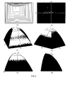
- FIG. 6 shows the curved surface obtained.
- the curved surface is vault shape and is obtained by synthesizing two crossing curves which are in orthogonal planes. This surface is referred to herein as the "orthogonal vault surface".
- the solid point is reference point
- the plane P1 and the plane P2 are reference planes (plane P2 is not shown in FIG. 6(e) and FIG. 6(f) )
- the hollow points are the projection points of the reference points on the reference planes (described below).
- FIG. 6(a) is the contour map of the curved surface, the rectangle outside represent the end plane of the initial frame (the end plane ABCD).
- FIG. 6(f) show the obtained curved surface stereoscopically, the rectangles at the bottom of which represent the end plane of the initial frame (the end plane ABCD).
- FIG. 6(a) and FIG. 6(b) represent watching from the front;
- FIG. 6(c) represents watching from the lower-left-front;
- FIG. 6(d) represent watching from the lower-right-front;
- FIG. 6(e) represent watching from below;
- FIG. 6(f) represent watching from the left.
- FIG. 6(e) and FIG. 6(f) represent watching from directions which offset at a tiny angle with respect to below or left, not accurately from below or left, by which to improve the stereoscopic feeling of the surfaces.
- FIG. 7 shows the curved surface of equation (4).
- This curved surface includes two intermediate curves in two orthogonal planes. This curved surface is referred to herein as the "orthogonal AM surface".
- the curve S in FIG. 7 is curve GPH.
- Other points, lines or planes in FIG. 7 are the same as in FIG. 6 .
- the reference point is projected to reference plane P1 along the curve S.
- the VOI may be obtained based on the curved surface.
- the initial frame 10 is cuboid ABCDKLMN, which includes six end planes: ABCD, ACKN, AKLB, BLMD, CNMD, KNML.
- the end plane ABCD may be replaced by the obtained curved surface described above. This curved surface can form a closed volume together with end planes ACKN, AKLB, BLMD, CNMD, KNML. This closed volume may serve as the expected VOI.
- the curved surface is obtained based on one reference point. In other embodiments, the curved surface may be obtained based on two or more reference points.
- FIG. 8 shows the curved surface obtained according to four reference points. The section shown in FIG. 8 is parallel to zx plane. Points T, U, V, W are reference points. In other embodiments, these reference points may be not located on the same section, but on different sections (not shown in FIG. 8 ).
- an algebraic surface which passes through these reference points may be created by methods which are similar to those described above, or a synthesized surface may be created by synthesizing two or more surfaces which pass through one or more reference points.
- This algebraic surface or combined surface is the expected curved surface.
- the created curves or curved surface pass through the reference points.
- the curves or curved surface may not pass through the reference points, but satisfy some constraint conditions based on the reference points.
- the distance between the curves or the curved surface and the reference point is a predefined value or meet predefined conditions, e.g., the reference point is the center or focus of the curve, or the reference point is the center or focus of the curved surface, etc. All of these curves or surfaces (including those passing through the reference point and those meeting the constraints conditions) are referred to as curves or surfaces "defined" by the reference points and other points.
- the curved surfaces are created on end plane ABCD of the initial frame. In other embodiments, the curved surfaces may also be created on one or at least two other end planes of the initial frame. Alternatively, the curved surfaces may be created on all of the six end planes of the initial frame. Then, the curved surfaces and the other end planes of the initial frame, or, all of the six curved surfaces, may form a closed volume, which is the expected VOI.
- the curved surfaces may be created only based on a predefined initial frame and selected reference points.
- the reference points may be selected arbitrarily based on requirements of imaging, facilitating ease of user operation. If the target of imaging is not located inside the initial frame, the initial frame need not move to make the initial frame contain the target. Reference points only need to be selected to make the created VOI based on the reference points contain the target. Moreover, the number and location of selected reference points are arbitrary. As a result, the VOI may be obtained whose shape is more corresponding to shape of the target by selecting the number and location of the reference points reasonably, by which to reduce background region contained in the VOI.
- the simplest way for selecting reference points is that the user directly inputs the coordinates of the reference points.
- the user may input the x coordinate, y coordinate and z coordinate of reference point into three input boxes supplied by imaging system.
- the coordinates of reference points may also be supplied by imaging system automatically, e.g., using any known edge or boundary detection methods to obtain expected points which will serve as reference points.
- reference points may also be selected in other ways, as described below.
- the view A, view B and view C are section views, and the view D is a 3D view.
- the three section views are mutually perpendicular.
- the corresponding sections of the VOI are also overlaid. If the VOI was cuboid (for example, the initial frame above) and the corresponding end planes were parallel to the section view respectively, then the section of the VOI separately overlaid on the section views is rectangle.
- FIG. 10 illustrates a method for selecting the reference points and defining VOI including steps 202, 204, 206, 208, 210, 212 and 214.
- step 202 an initial frame of the VOI in the ultrasound imaging space is defined.
- step 204 selecting signals for selecting an initial reference point are received in order to select at least one initial reference point at an arbitrary location in the imaging space.
- the selecting signals may be generated by the imaging system automatically or by user input.
- selecting signals are received for selecting at least one reference plane in the ultrasound imaging space.
- the selected reference planes may be one or more of the planes of view A, view B and view C in FIG. 9 .
- one or more of the other planes may be selected as reference plane(s).
- the section views displayed on the display may be changed to make the section views located on the selected reference planes to be displayed in view A, view B or view C.
- these selecting signals may be generated by the imaging system automatically or by user input.
- selecting signals are received for a selecting proxy reference point to select at least one proxy reference point at an arbitrary location of the reference plane.
- the locations of the proxy reference points are not limited. These selecting signals may be generated by the imaging system automatically, such as the imaging system directly gives the coordinates of the proxy reference points. These selecting signals may also be generated by user input, such as the user inputting the coordinates of the proxy reference points, or clicking the mouse to select points which would be proxy reference points in the reference plane.
- the number of the proxy reference points is not limited and may be one or more.
- the relationship between the initial reference points and the reference planes are determined.
- the initial reference points and the reference planes may be corresponded according to certain rules to obtain the corresponding points of the initial reference points in the reference planes.
- the simplest rule is vertical projection, e.g., projecting vertically the initial reference points to the reference planes.
- the projection points are the corresponding points.
- the initial reference points may be "projected" to the reference planes along oblique lines or curves, e.g., calculating the intersection points of the reference planes and the oblique lines or curves which pass through the initial reference points.
- the intersection points are the corresponding points.
- the initial reference points may be calculated (assuming that the initial reference points were not known) according to a "reversed projection relationship.”
- corresponding points out of the reference planes can also be calculated according to the reversed projection relationship above. These corresponding points calculated by the reversed projection relationship are referred to herein as "reversed projection points”.
- the projection relationships are not limited. They may be any relationship which satisfy requirements.
- the projection relationship to be used may be selected by the imaging system or by the user via the user interface.
- the reversed projection points of the selected proxy reference points may be calculated. These reversed projection points then are used as the reference points being selected.
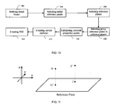
- the projection relationship is vertical projection.
- point O is initial reference point.
- Point O is projected vertically to the reference plane.
- Point O' is the projection point.
- Point J is the selected proxy reference point.
- Point J' is the reversed projection point, that is, the reference point.
- the coordinates of the initial reference point O are (x1, y1, z1) and the coordinate of the reference plane is z2, then the coordinates of the projection point O' are (x1, y1, z2).
- the coordinates of the selected proxy reference point J are (x2, y2)
- the coordinates of point J are (x2, y2, z2)
- the coordinates of the reversed projection point J' of the projection point J are (x2, y2, z1). That is, the coordinates of the reference point are (x2, y2, z1).
- the coordinates of the selected proxy reference point in the reference plane were (x2', y3, z2')
- the coordinates of the reversed projection point of the proxy reference point are (x2', g -1 (z2'), z2')
- the function g -1 () is inverse function of function g().
- the initial reference points may be projected to the reference plane along the interim curves. As FIG. 7 shows, the initial reference point (solid point in FIG. 7 ) is projected to the reference plane P1 along interim curve S.
- step 212 create at least one curved surface using at least one of the reference points and at least one of the elements of the initial frame;
- step 214 create the VOI based on the at least one curved surface.
- steps 206, 208 and 210 steps 202, 204, 212 and 214 are same or similar with steps 102, 104, 106 and 108 above.
- the proxy reference points may be obtained by moving the projection points of the initial reference points in the reference planes. That is, after selecting the initial reference points, the projection points of the initial reference points in the reference planes may be calculated and displayed, then these projection points may be moved to expected locations using, for example, a mouse. These points in new locations then are used as the proxy reference points.
- the proxy reference points may be adjusted or updated. That is, signals for adjusting or updating the proxy reference points may be received, then the locations of the proxy reference points may be adjusted or updated according to the signals, which may be inputted by the user.
- the obtained VOI may be "updated" by selecting new proxy reference points in the reference plane and then calculating new reference points using the methods described above. That is, new proxy reference points may be selected, then reference points may be recalculated using the methods described above based on the selected new proxy reference points, the curved surfaces may be recalculated based on the new reference points according to steps 106, 108 or steps 212, 214 described above, and then, the VOI may be redefined based on the recalculated curved surfaces. In this way, the VOI may be adjusted to better satisfy the requirements of the user.
- the rendering unit of the 3D imaging module for implementing the rendering step in FIG. 2 includes an apparatus for defining the VOI in the ultrasound imaging space.
- the apparatus may include a reference points selecting unit 302, an initial frame defining unit 304, a curved surfaces creating unit 306, and a VOI defining unit 308, wherein the reference points selecting unit 302 and initial frame defining unit 304 are in communication with the curved surfaces creating unit 306, which is in communication with the VOI defining unit 308.
- the initial frame defining unit 304 defines the initial frame of the VOI in the ultrasound imaging space.
- the reference points selecting unit 302 receives the signals for selecting the reference points and selects at least one reference point at an arbitrary location in the ultrasound imaging space according to the signals.
- the curved surfaces creating unit 306 receives the initial frame defined by the initial frame defining unit 304 and the reference points selected by the reference points selecting unit 302 and creates at least one curved surface based on at least one of the reference points and at least one element of the initial frame.
- the VOI defining unit 308 receives the curved surfaces created by the curved surfaces creating unit 306 and defines the VOI based on the curved surfaces.
- the creating curved surface unit 306 may use the methods of step 106 or step 212 above to create the curved surface.
- the creating curved surface unit 306 may include a projection points calculating sub-unit, which calculates the projection points of the reference points on the initial frame along at least two directions; an interim curves creating sub-unit, which creates the curves defined by the reference point and its projection points on the initial frame in each projection directions to obtain at least two interim curves; and/or a curved surfaces creating sub-unit, which creates curved surfaces based on the at least two interim curves.
- the apparatus may further include a user interface unit 314, as shown in FIG. 13 .
- the user interface unit 314 is in communication with at least one of the reference points selecting unit 302 and the initial frame defining unit 304.
- the user interface unit 314 may also be connected to the display unit 312. As a result, the user can select or adjust the reference points and/or the initial frame of the VOI by the user interface unit 314.
- the apparatus may further include a reference planes selecting unit 316, a proxy reference points selecting unit 318, and a reference points updating unit 320, as shown in FIG. 14 .
- the reference planes selecting unit 316 is in communication with the proxy reference points selecting unit 318, which is in communication with the reference points updating unit 320.
- the reference points updating unit 320 is in communication with the creating curved surface unit 306.
- the selecting reference plane unit 316 receives the signals for selecting the reference planes and selects at least one reference plane in the ultrasound imaging space according to these signals.
- the proxy reference points selecting unit 318 receives the signals for selecting the proxy reference points and selects at least one proxy reference point in the arbitrary location of the reference plane according to these signals.
- the reference points updating unit 320 calculates the reversed projection points of the proxy reference points selected by the proxy reference points selecting unit 318 according to the "reversed projection relationship" which is reversed to the projection relationship according to which the reference points selected by the reference points selecting unit 302 are projected to the reference plane. Then, the calculated reversed projection points are the new reference points.
- the reference points selected by the reference points selecting unit 302 are referred to herein as "initial reference points,” and the reference points selecting unit 302 may be referred to as the "selecting initial reference points unit".
- the signals for selecting the proxy reference points received by the proxy reference points selecting unit 318 may come from the imaging system or user input.
- the proxy reference points selecting unit 318 may include a projection points calculating sub-unit, which calculates at least one projection point of the reference points in the reference planes; and a projection points moving sub-unit, which receives the signals for selecting proxy reference points and moves the projection points according to this signals.
- the moved projection points are the proxy reference points.
- the signals received by the projection points moving sub-unit may come from the imaging system or input of the user (for example, dragging the projection points by a mouse).
- the proxy reference points selecting unit 318 may further include a displaying projection points sub-unit, which displays the calculated projection points.
- the user interface unit 314 may be in communication with at least one of the reference points selecting unit 302, the initial frame defining unit 304, the selecting reference plane unit 316, the proxy reference points selecting unit 318, and the reference points updating unit 320. Accordingly, the user can select or adjust the reference points, the initial reference points, the reference plane, the proxy reference points or the initial frame, etc., through the user interface.
- Embodiments may include various steps, which may be embodied in machine-executable instructions to be executed by a general-purpose or special-purpose computer (or other electronic device). Alternatively, the steps may be performed by hardware components that include specific logic for performing the steps or by a combination of hardware, software, and/or firmware.
- Embodiments may also be provided as a computer program product including a machine-readable medium having stored thereon instructions that may be used to program a computer (or other electronic device) to perform processes described herein.
- the machine-readable medium may include, but is not limited to, hard drives, floppy diskettes, optical disks, CD-ROMs, DVD-ROMs, ROMs, RAMS, EPROMs, EEPROMs, magnetic or optical cards, solid-state memory devices, or other types of media/machine-readable medium suitable for storing electronic instructions.
Landscapes
- Engineering & Computer Science (AREA)
- Physics & Mathematics (AREA)
- General Physics & Mathematics (AREA)
- Theoretical Computer Science (AREA)
- Computer Vision & Pattern Recognition (AREA)
- General Engineering & Computer Science (AREA)
- Computer Networks & Wireless Communication (AREA)
- Computer Graphics (AREA)
- Computer Hardware Design (AREA)
- Software Systems (AREA)
- Remote Sensing (AREA)
- Radar, Positioning & Navigation (AREA)
- Data Mining & Analysis (AREA)
- Geometry (AREA)
- Bioinformatics & Cheminformatics (AREA)
- Bioinformatics & Computational Biology (AREA)
- Evolutionary Biology (AREA)
- Evolutionary Computation (AREA)
- Artificial Intelligence (AREA)
- Life Sciences & Earth Sciences (AREA)
- Ultra Sonic Daignosis Equipment (AREA)
Applications Claiming Priority (1)
| Application Number | Priority Date | Filing Date | Title |
|---|---|---|---|
| CN2009102257160A CN102081697B (zh) | 2009-11-27 | 2009-11-27 | 一种在超声成像空间中定义感兴趣容积的方法及其装置 |
Publications (3)
| Publication Number | Publication Date |
|---|---|
| EP2333577A2 true EP2333577A2 (fr) | 2011-06-15 |
| EP2333577A3 EP2333577A3 (fr) | 2012-10-24 |
| EP2333577B1 EP2333577B1 (fr) | 2016-12-28 |
Family
ID=43733950
Family Applications (1)
| Application Number | Title | Priority Date | Filing Date |
|---|---|---|---|
| EP10015053.1A Active EP2333577B1 (fr) | 2009-11-27 | 2010-11-26 | Procédés et systèmes permettant de définir un VOI dans un espace d'imagerie ultrasonore |
Country Status (3)
| Country | Link |
|---|---|
| US (2) | US8781196B2 (fr) |
| EP (1) | EP2333577B1 (fr) |
| CN (1) | CN102081697B (fr) |
Cited By (1)
| Publication number | Priority date | Publication date | Assignee | Title |
|---|---|---|---|---|
| EP2924656A1 (fr) * | 2014-03-28 | 2015-09-30 | Hitachi Aloka Medical, Ltd. | Appareil et procédé de génération d'image de diagnostic |
Families Citing this family (8)
| Publication number | Priority date | Publication date | Assignee | Title |
|---|---|---|---|---|
| CN102081697B (zh) * | 2009-11-27 | 2013-12-11 | 深圳迈瑞生物医疗电子股份有限公司 | 一种在超声成像空间中定义感兴趣容积的方法及其装置 |
| US10835210B2 (en) * | 2015-03-30 | 2020-11-17 | Siemens Medical Solutions Usa, Inc. | Three-dimensional volume of interest in ultrasound imaging |
| CN107647880B (zh) * | 2016-07-26 | 2021-01-19 | 东芝医疗系统株式会社 | 医用图像处理装置以及医用图像处理方法 |
| CN106725614B (zh) * | 2016-12-29 | 2021-03-30 | 深圳开立生物医疗科技股份有限公司 | 超声成像设备、超声成像方法及装置 |
| CN109259801B (zh) * | 2018-09-12 | 2021-05-14 | 深圳开立生物医疗科技股份有限公司 | 一种剪切波弹性成像方法及装置 |
| WO2020093402A1 (fr) * | 2018-11-09 | 2020-05-14 | 深圳迈瑞生物医疗电子股份有限公司 | Procédé d'acquisition d'image ultrasonore, système et milieu de stockage informatique |
| EP4125610B1 (fr) * | 2020-04-03 | 2023-08-02 | Koninklijke Philips N.V. | Procédé mis en oeuvre par ordinateur pour la visualisation d'une structure anatomique allongée |
| CN114463165B (zh) * | 2021-09-28 | 2025-02-14 | 西安大医集团股份有限公司 | 感兴趣体积voi确定方法及装置 |
Citations (1)
| Publication number | Priority date | Publication date | Assignee | Title |
|---|---|---|---|---|
| US7433504B2 (en) | 2004-08-27 | 2008-10-07 | General Electric Company | User interactive method for indicating a region of interest |
Family Cites Families (86)
| Publication number | Priority date | Publication date | Assignee | Title |
|---|---|---|---|---|
| US5555352A (en) * | 1991-04-23 | 1996-09-10 | International Business Machines Corporation | Object-based irregular-grid volume rendering |
| US5920319A (en) * | 1994-10-27 | 1999-07-06 | Wake Forest University | Automatic analysis in virtual endoscopy |
| DE19723095C2 (de) * | 1997-06-02 | 2001-08-23 | Siemens Ag | Bildrekonstruktionsverfahren für einen Computertomographen |
| US6740883B1 (en) * | 1998-08-14 | 2004-05-25 | Robert Z. Stodilka | Application of scatter and attenuation correction to emission tomography images using inferred anatomy from atlas |
| US6687393B1 (en) * | 1999-07-16 | 2004-02-03 | General Electric Company | Efficient methods and apparatus for resampling three dimensional datasets |
| US7006085B1 (en) * | 2000-10-30 | 2006-02-28 | Magic Earth, Inc. | System and method for analyzing and imaging three-dimensional volume data sets |
| US7103205B2 (en) * | 2000-11-24 | 2006-09-05 | U-Systems, Inc. | Breast cancer screening with ultrasound image overlays |
| EP1362329B1 (fr) * | 2001-02-13 | 2019-03-27 | Koninklijke Philips N.V. | Traitement d'images dans un sens de succession |
| US6638221B2 (en) * | 2001-09-21 | 2003-10-28 | Kabushiki Kaisha Toshiba | Ultrasound diagnostic apparatus, and image processing method |
| US7379572B2 (en) * | 2001-10-16 | 2008-05-27 | University Of Chicago | Method for computer-aided detection of three-dimensional lesions |
| US6738063B2 (en) * | 2002-02-07 | 2004-05-18 | Siemens Corporate Research, Inc. | Object-correspondence identification without full volume registration |
| US7346381B2 (en) * | 2002-11-01 | 2008-03-18 | Ge Medical Systems Global Technology Company Llc | Method and apparatus for medical intervention procedure planning |
| US7362889B2 (en) * | 2002-05-10 | 2008-04-22 | Massachusetts Institute Of Technology | Elastomeric actuator devices for magnetic resonance imaging |
| JP3928506B2 (ja) * | 2002-07-08 | 2007-06-13 | 松下電器産業株式会社 | 3次元超音波診断装置 |
| JP2004141514A (ja) * | 2002-10-28 | 2004-05-20 | Toshiba Corp | 画像処理装置及び超音波診断装置 |
| DE10254908B4 (de) * | 2002-11-25 | 2006-11-30 | Siemens Ag | Verfahren zum Herstellen eines Bildes |
| GB2395880B (en) * | 2002-11-27 | 2005-02-02 | Voxar Ltd | Curved multi-planar reformatting of three-dimensional volume data sets |
| US20040138560A1 (en) * | 2002-12-02 | 2004-07-15 | Gianluca Paladini | Real-time scan conversion and rendering of ultrasound data |
| GB2398469B (en) * | 2003-02-12 | 2005-10-26 | Canon Europa Nv | Image processing apparatus |
| US6852081B2 (en) * | 2003-03-13 | 2005-02-08 | Siemens Medical Solutions Usa, Inc. | Volume rendering in the acoustic grid methods and systems for ultrasound diagnostic imaging |
| EP2460474B1 (fr) * | 2003-05-08 | 2015-12-16 | Hitachi Medical Corporation | Procédé d'affichage d'images de référence pour échographie et appareil de diagnostic à ultrasons |
| US6909914B2 (en) * | 2003-06-13 | 2005-06-21 | Esaote, S.P.A. | Method for generating time independent images of moving objects |
| ATE550680T1 (de) * | 2003-09-30 | 2012-04-15 | Esaote Spa | Methode zur positions- und geschwindigkeitsverfolgung eines objektrandes in zwei- oder dreidimensionalen digitalen echographischen bildern |
| EP1523939B1 (fr) * | 2003-10-14 | 2012-03-07 | Olympus Corporation | Dispositif de diagnostique à ultrasons |
| US7447341B2 (en) * | 2003-11-26 | 2008-11-04 | Ge Medical Systems Global Technology Company, Llc | Methods and systems for computer aided targeting |
| US7727151B2 (en) * | 2003-11-28 | 2010-06-01 | U-Systems Inc. | Navigation among multiple breast ultrasound volumes |
| CN101023448A (zh) * | 2004-02-10 | 2007-08-22 | 芝加哥大学 | 成像系统 |
| DE102004015383B4 (de) * | 2004-03-26 | 2006-04-13 | SAM Präzisionstechnik GmbH | Kombinationsvorrichtung zur Registrierung der Unterkieferbewegungen in Bezug auf den Schädel einerseits und zur schädelgerechten Übertragung von Oberkiefermodellen in einen Artikulator andererseits |
| US20050234340A1 (en) * | 2004-03-31 | 2005-10-20 | Brock-Fisher George A | Bolus control for contrast imaging with 3D |
| KR100686289B1 (ko) * | 2004-04-01 | 2007-02-23 | 주식회사 메디슨 | 대상체 영상의 윤곽내 볼륨 데이터를 이용하는 3차원초음파 영상 형성 장치 및 방법 |
| US20050237336A1 (en) * | 2004-04-23 | 2005-10-27 | Jens Guhring | Method and system for multi-object volumetric data visualization |
| US7714855B2 (en) * | 2004-05-17 | 2010-05-11 | Siemens Medical Solutions Usa, Inc. | Volume rendering processing distribution in a graphics processing unit |
| US7428334B2 (en) * | 2004-08-27 | 2008-09-23 | General Electric Company | Methods and systems for 3D segmentation of ultrasound images |
| US7471815B2 (en) * | 2004-08-31 | 2008-12-30 | Siemens Medical Solutions Usa, Inc. | Candidate generation for lung nodule detection |
| EP1677253A1 (fr) * | 2004-12-30 | 2006-07-05 | GSF-Forschungszentrum für Umwelt und Gesundheit GmbH | Procédé et dispositif pour la reconstruction d'une fonction d'image multidimensionelle à partir de données de Radon |
| JP4335817B2 (ja) * | 2005-01-07 | 2009-09-30 | ザイオソフト株式会社 | 関心領域指定方法、関心領域指定プログラム、関心領域指定装置 |
| US20080170765A1 (en) * | 2005-04-25 | 2008-07-17 | Koninklijke Philips Electronics, N.V. | Targeted Additive Gain Tool For Processing Ultrasound Images |
| US7852335B2 (en) * | 2005-05-09 | 2010-12-14 | Siemens Medical Solutions Usa, Inc. | Volume rendering processing distribution in a graphics processing unit |
| US9314222B2 (en) * | 2005-07-07 | 2016-04-19 | Stereotaxis, Inc. | Operation of a remote medical navigation system using ultrasound image |
| US20070038065A1 (en) * | 2005-07-07 | 2007-02-15 | Creighton Francis M Iv | Operation of a remote medical navigation system using ultrasound image |
| US20070052700A1 (en) * | 2005-09-07 | 2007-03-08 | Wheeler Frederick W | System and method for 3D CAD using projection images |
| WO2007046074A1 (fr) * | 2005-10-20 | 2007-04-26 | Koninklijke Philips Electronics N.V. | Systeme et procede d'imagerie ultrasonique |
| KR100859434B1 (ko) * | 2005-11-01 | 2008-09-23 | 주식회사 메디슨 | 다중 단면영상을 이용한 컨투어 편집 기능을 제공하는 영상처리 시스템 및 방법 |
| CA2644641A1 (fr) * | 2006-03-17 | 2007-09-27 | Koninklijke Philips Electronics, N.V. | Systemes et procedes pour definition interactive de regions et de volumes d'interet |
| ITTO20060223A1 (it) * | 2006-03-24 | 2007-09-25 | I Med S R L | Procedimento e sistema per il riconoscimento automatico di anomalie preneoplastiche in strutture anatomiche, e relativo programma per elaboratore |
| US7889194B2 (en) * | 2006-03-30 | 2011-02-15 | Siemens Medical Solutions Usa, Inc. | System and method for in-context MPR visualization using virtual incision volume visualization |
| US20070255139A1 (en) * | 2006-04-27 | 2007-11-01 | General Electric Company | User interface for automatic multi-plane imaging ultrasound system |
| JP4864554B2 (ja) | 2006-06-12 | 2012-02-01 | 株式会社東芝 | 超音波診断装置、医用画像処理装置、及び医用画像処理プログラム |
| WO2008044572A1 (fr) * | 2006-10-04 | 2008-04-17 | Hitachi Medical Corporation | dispositif de diagnostic d'images médicales |
| JP2008104798A (ja) * | 2006-10-27 | 2008-05-08 | Ziosoft Inc | 画像処理方法 |
| AU2007317262B2 (en) * | 2006-11-09 | 2011-10-20 | Amo Wavefront Sciences, Llc. | Method and apparatus for obtaining the distance from an optical measurement instrument to and object under test |
| US8303502B2 (en) * | 2007-03-06 | 2012-11-06 | General Electric Company | Method and apparatus for tracking points in an ultrasound image |
| KR101028354B1 (ko) | 2007-03-20 | 2011-06-14 | 주식회사 메디슨 | 초음파 영상을 형성하는 초음파 시스템 및 방법 |
| CN101292883B (zh) | 2007-04-23 | 2012-07-04 | 深圳迈瑞生物医疗电子股份有限公司 | 超声三维快速成像方法及其装置 |
| US20080267467A1 (en) * | 2007-04-30 | 2008-10-30 | General Electric Company | Method and system for automatic adjustment of a diagnostic imaging display |
| GB0718614D0 (en) * | 2007-05-16 | 2007-10-31 | Seereal Technologies Sa | Holograms |
| US20080287799A1 (en) * | 2007-05-16 | 2008-11-20 | General Electric Company | Method and apparatus for measuring volumetric flow |
| DE102007026520A1 (de) * | 2007-06-08 | 2008-12-11 | Siemens Ag | Bildakquisitons-, Bildarchivierungs- und Bildrenderingsystem zur Reproduzierung von eingestellten Untersuchungsparametern einer CT-, PET-CT- bzw. MRT- gestützten Erstuntersuchung bei nachfolgenden radiologischen Kontrolluntersuchungen |
| US8540635B2 (en) * | 2007-07-12 | 2013-09-24 | Siemens Medical Solutions Usa, Inc. | Medical diagnostic imaging with hardware generated region of interest border |
| US8135198B2 (en) * | 2007-08-08 | 2012-03-13 | Resonant Medical, Inc. | Systems and methods for constructing images |
| US8009887B2 (en) * | 2007-11-02 | 2011-08-30 | Siemens Corporation | Method and system for automatic quantification of aortic valve function from 4D computed tomography data using a physiological model |
| US9651662B2 (en) * | 2007-11-16 | 2017-05-16 | Koninklijke Philips N.V. | Interventional navigation using 3D contrast-enhanced ultrasound |
| JP5364290B2 (ja) * | 2008-04-17 | 2013-12-11 | 富士フイルム株式会社 | 画像表示装置並びに画像表示制御方法およびプログラム |
| EP2130497A1 (fr) * | 2008-06-05 | 2009-12-09 | Medison Co., Ltd. | Extraction de fonction anatomique à partir d'une image de foie à ultrasons |
| JP4541434B2 (ja) * | 2008-07-14 | 2010-09-08 | ザイオソフト株式会社 | 画像処理装置及び画像処理プログラム |
| JP4998399B2 (ja) * | 2008-07-25 | 2012-08-15 | 富士通株式会社 | 情報処理装置、情報処理方法および情報処理プログラム |
| KR101083936B1 (ko) * | 2008-09-26 | 2011-11-15 | 삼성메디슨 주식회사 | 초음파 데이터 처리 장치 및 방법 |
| KR101068917B1 (ko) * | 2009-05-18 | 2011-09-30 | 삼성메디슨 주식회사 | 기관 표시를 위한 초음파 진단기 및 방법 |
| KR101121353B1 (ko) * | 2009-08-03 | 2012-03-09 | 한국과학기술원 | 2차원 초음파 영상에 대응하는 2차원 ct 영상을 제공하는 시스템 및 방법 |
| EP2478494A1 (fr) * | 2009-09-14 | 2012-07-25 | Exxonmobil Upstream Research Company | Système et procédé de visualisation correspondant à des objets physiques |
| CN102081697B (zh) * | 2009-11-27 | 2013-12-11 | 深圳迈瑞生物医疗电子股份有限公司 | 一种在超声成像空间中定义感兴趣容积的方法及其装置 |
| US8977377B2 (en) * | 2010-02-25 | 2015-03-10 | Jostens, Inc. | Method for digital manufacturing of jewelry items |
| US8582865B2 (en) * | 2010-04-28 | 2013-11-12 | General Electric Company | Ultrasound imaging with ray casting and software-based image reconstruction |
| CN102274042B (zh) * | 2010-06-08 | 2013-09-04 | 深圳迈瑞生物医疗电子股份有限公司 | 图像配准方法、宽景成像方法、超声成像方法及其系统 |
| JP5623157B2 (ja) * | 2010-06-30 | 2014-11-12 | 富士フイルム株式会社 | 超音波診断装置及びその作動方法 |
| JP5660432B2 (ja) * | 2010-06-30 | 2015-01-28 | 独立行政法人理化学研究所 | 領域データ編集装置、領域データ編集方法、プログラム、及び、記録媒体 |
| US20120007851A1 (en) * | 2010-07-12 | 2012-01-12 | Kazuhiko Matsumoto | Method for display of images utilizing curved planar reformation techniques |
| CA2806197A1 (fr) * | 2010-08-05 | 2012-02-09 | Exxonmobil Upstream Research Company | Obtention de donnees a partir d'un modele terrestre au moyen de descripteurs fonctionnels |
| US8731875B2 (en) * | 2010-08-13 | 2014-05-20 | Exxonmobil Upstream Research Company | System and method for providing data corresponding to physical objects |
| JP5689678B2 (ja) * | 2010-12-27 | 2015-03-25 | 株式会社東芝 | 超音波装置 |
| US10575757B2 (en) * | 2011-08-16 | 2020-03-03 | Koninklijke Philips N.V. | Curved multi-planar reconstruction using fiber optic shape data |
| JP5972561B2 (ja) * | 2011-12-08 | 2016-08-17 | 東芝メディカルシステムズ株式会社 | 超音波診断装置、画像処理装置及び画像処理プログラム |
| KR101364527B1 (ko) * | 2011-12-27 | 2014-02-19 | 삼성메디슨 주식회사 | 대상체의 움직임 프로파일 정보를 제공하는 초음파 시스템 및 방법 |
| US20140029820A1 (en) * | 2012-01-20 | 2014-01-30 | Carl Zeiss Meditec, Inc. | Differential geometric metrics characterizing optical coherence tomography data |
| US9235931B2 (en) * | 2012-05-18 | 2016-01-12 | Eiffel Medtech Inc. | Method and system for the three-dimensional reconstruction of structures |
| US20130328874A1 (en) * | 2012-06-06 | 2013-12-12 | Siemens Medical Solutions Usa, Inc. | Clip Surface for Volume Rendering in Three-Dimensional Medical Imaging |
-
2009
- 2009-11-27 CN CN2009102257160A patent/CN102081697B/zh active Active
-
2010
- 2010-11-22 US US12/951,935 patent/US8781196B2/en active Active
- 2010-11-26 EP EP10015053.1A patent/EP2333577B1/fr active Active
-
2014
- 2014-07-10 US US14/328,497 patent/US9721355B2/en active Active
Patent Citations (1)
| Publication number | Priority date | Publication date | Assignee | Title |
|---|---|---|---|---|
| US7433504B2 (en) | 2004-08-27 | 2008-10-07 | General Electric Company | User interactive method for indicating a region of interest |
Cited By (1)
| Publication number | Priority date | Publication date | Assignee | Title |
|---|---|---|---|---|
| EP2924656A1 (fr) * | 2014-03-28 | 2015-09-30 | Hitachi Aloka Medical, Ltd. | Appareil et procédé de génération d'image de diagnostic |
Also Published As
| Publication number | Publication date |
|---|---|
| US9721355B2 (en) | 2017-08-01 |
| US8781196B2 (en) | 2014-07-15 |
| US20110129137A1 (en) | 2011-06-02 |
| EP2333577B1 (fr) | 2016-12-28 |
| EP2333577A3 (fr) | 2012-10-24 |
| CN102081697B (zh) | 2013-12-11 |
| US20140341458A1 (en) | 2014-11-20 |
| CN102081697A (zh) | 2011-06-01 |
Similar Documents
| Publication | Publication Date | Title |
|---|---|---|
| US9721355B2 (en) | Methods and systems for defining a VOI in an ultrasound imaging space | |
| Mohamed et al. | A survey on 3D ultrasound reconstruction techniques | |
| JP5637653B2 (ja) | 医用画像処理装置、超音波診断装置、及び医用画像処理プログラム | |
| JP5495357B2 (ja) | 画像表示方法及び医用画像診断システム | |
| JP4470187B2 (ja) | 超音波装置、超音波撮像プログラム及び超音波撮像方法 | |
| JP5433240B2 (ja) | 超音波診断装置及び画像表示装置 | |
| JP5400466B2 (ja) | 画像診断装置、画像診断方法 | |
| JP5631629B2 (ja) | 超音波画像処理装置及び超音波診断装置 | |
| KR102267060B1 (ko) | 초음파 영상 장치 및 그 제어 방법 | |
| CN105769240B (zh) | 显示医学图像的设备和方法 | |
| KR101100464B1 (ko) | 부 관심영역에 기초하여 3차원 초음파 영상을 제공하는 초음파 시스템 및 방법 | |
| US8810568B2 (en) | Methods and apparatuses for creating orientation markers and 3D ultrasound imaging systems using the same | |
| CN108885797A (zh) | 成像系统和方法 | |
| JP2001084409A (ja) | 三次元画像処理方法及び三次元画像処理装置 | |
| JP2001276066A (ja) | 三次元画像処理装置 | |
| JP5942217B2 (ja) | 超音波診断装置、超音波画像処理装置及び超音波画像処理プログラム | |
| JP5305635B2 (ja) | 医用画像表示装置 | |
| JP5583472B2 (ja) | 医用画像診断装置及び制御プログラム | |
| JP2008029694A (ja) | 画像処理装置及び該画像処理装置を備える医用診断装置 | |
| JP5701362B2 (ja) | 画像診断装置、画像診断方法 | |
| JP2019170412A (ja) | 手術シミュレーション装置及び手術シミュレーションプログラム | |
| JP2024114266A (ja) | 医用画像処理装置、超音波診断装置、及び医用画像処理プログラム |
Legal Events
| Date | Code | Title | Description |
|---|---|---|---|
| PUAI | Public reference made under article 153(3) epc to a published international application that has entered the european phase |
Free format text: ORIGINAL CODE: 0009012 |
|
| AK | Designated contracting states |
Kind code of ref document: A2 Designated state(s): AL AT BE BG CH CY CZ DE DK EE ES FI FR GB GR HR HU IE IS IT LI LT LU LV MC MK MT NL NO PL PT RO RS SE SI SK SM TR |
|
| AX | Request for extension of the european patent |
Extension state: BA ME |
|
| PUAL | Search report despatched |
Free format text: ORIGINAL CODE: 0009013 |
|
| AK | Designated contracting states |
Kind code of ref document: A3 Designated state(s): AL AT BE BG CH CY CZ DE DK EE ES FI FR GB GR HR HU IE IS IT LI LT LU LV MC MK MT NL NO PL PT RO RS SE SI SK SM TR |
|
| AX | Request for extension of the european patent |
Extension state: BA ME |
|
| RIC1 | Information provided on ipc code assigned before grant |
Ipc: G06T 19/00 20110101ALI20120920BHEP Ipc: G01S 15/89 20060101ALI20120920BHEP Ipc: A61B 8/14 20060101ALI20120920BHEP Ipc: G01S 7/52 20060101AFI20120920BHEP |
|
| 17P | Request for examination filed |
Effective date: 20130424 |
|
| 17Q | First examination report despatched |
Effective date: 20130607 |
|
| GRAP | Despatch of communication of intention to grant a patent |
Free format text: ORIGINAL CODE: EPIDOSNIGR1 |
|
| RIC1 | Information provided on ipc code assigned before grant |
Ipc: G01S 15/89 20060101ALI20160614BHEP Ipc: G06T 7/00 20060101ALI20160614BHEP Ipc: G01S 7/52 20060101AFI20160614BHEP Ipc: A61B 8/08 20060101ALI20160614BHEP Ipc: G06T 19/00 20110101ALI20160614BHEP Ipc: A61B 8/00 20060101ALI20160614BHEP |
|
| INTG | Intention to grant announced |
Effective date: 20160627 |
|
| GRAS | Grant fee paid |
Free format text: ORIGINAL CODE: EPIDOSNIGR3 |
|
| GRAA | (expected) grant |
Free format text: ORIGINAL CODE: 0009210 |
|
| AK | Designated contracting states |
Kind code of ref document: B1 Designated state(s): AL AT BE BG CH CY CZ DE DK EE ES FI FR GB GR HR HU IE IS IT LI LT LU LV MC MK MT NL NO PL PT RO RS SE SI SK SM TR |
|
| REG | Reference to a national code |
Ref country code: GB Ref legal event code: FG4D |
|
| REG | Reference to a national code |
Ref country code: CH Ref legal event code: EP |
|
| REG | Reference to a national code |
Ref country code: AT Ref legal event code: REF Ref document number: 857771 Country of ref document: AT Kind code of ref document: T Effective date: 20170115 |
|
| REG | Reference to a national code |
Ref country code: IE Ref legal event code: FG4D |
|
| REG | Reference to a national code |
Ref country code: DE Ref legal event code: R096 Ref document number: 602010039089 Country of ref document: DE |
|
| PG25 | Lapsed in a contracting state [announced via postgrant information from national office to epo] |
Ref country code: LV Free format text: LAPSE BECAUSE OF FAILURE TO SUBMIT A TRANSLATION OF THE DESCRIPTION OR TO PAY THE FEE WITHIN THE PRESCRIBED TIME-LIMIT Effective date: 20161228 |
|
| REG | Reference to a national code |
Ref country code: NL Ref legal event code: FP |
|
| REG | Reference to a national code |
Ref country code: LT Ref legal event code: MG4D |
|
| PG25 | Lapsed in a contracting state [announced via postgrant information from national office to epo] |
Ref country code: SE Free format text: LAPSE BECAUSE OF FAILURE TO SUBMIT A TRANSLATION OF THE DESCRIPTION OR TO PAY THE FEE WITHIN THE PRESCRIBED TIME-LIMIT Effective date: 20161228 Ref country code: GR Free format text: LAPSE BECAUSE OF FAILURE TO SUBMIT A TRANSLATION OF THE DESCRIPTION OR TO PAY THE FEE WITHIN THE PRESCRIBED TIME-LIMIT Effective date: 20170329 Ref country code: NO Free format text: LAPSE BECAUSE OF FAILURE TO SUBMIT A TRANSLATION OF THE DESCRIPTION OR TO PAY THE FEE WITHIN THE PRESCRIBED TIME-LIMIT Effective date: 20170328 Ref country code: LT Free format text: LAPSE BECAUSE OF FAILURE TO SUBMIT A TRANSLATION OF THE DESCRIPTION OR TO PAY THE FEE WITHIN THE PRESCRIBED TIME-LIMIT Effective date: 20161228 |
|
| REG | Reference to a national code |
Ref country code: AT Ref legal event code: MK05 Ref document number: 857771 Country of ref document: AT Kind code of ref document: T Effective date: 20161228 |
|
| PG25 | Lapsed in a contracting state [announced via postgrant information from national office to epo] |
Ref country code: RS Free format text: LAPSE BECAUSE OF FAILURE TO SUBMIT A TRANSLATION OF THE DESCRIPTION OR TO PAY THE FEE WITHIN THE PRESCRIBED TIME-LIMIT Effective date: 20161228 Ref country code: HR Free format text: LAPSE BECAUSE OF FAILURE TO SUBMIT A TRANSLATION OF THE DESCRIPTION OR TO PAY THE FEE WITHIN THE PRESCRIBED TIME-LIMIT Effective date: 20161228 Ref country code: FI Free format text: LAPSE BECAUSE OF FAILURE TO SUBMIT A TRANSLATION OF THE DESCRIPTION OR TO PAY THE FEE WITHIN THE PRESCRIBED TIME-LIMIT Effective date: 20161228 |
|
| PG25 | Lapsed in a contracting state [announced via postgrant information from national office to epo] |
Ref country code: IS Free format text: LAPSE BECAUSE OF FAILURE TO SUBMIT A TRANSLATION OF THE DESCRIPTION OR TO PAY THE FEE WITHIN THE PRESCRIBED TIME-LIMIT Effective date: 20170428 Ref country code: CZ Free format text: LAPSE BECAUSE OF FAILURE TO SUBMIT A TRANSLATION OF THE DESCRIPTION OR TO PAY THE FEE WITHIN THE PRESCRIBED TIME-LIMIT Effective date: 20161228 Ref country code: EE Free format text: LAPSE BECAUSE OF FAILURE TO SUBMIT A TRANSLATION OF THE DESCRIPTION OR TO PAY THE FEE WITHIN THE PRESCRIBED TIME-LIMIT Effective date: 20161228 Ref country code: SK Free format text: LAPSE BECAUSE OF FAILURE TO SUBMIT A TRANSLATION OF THE DESCRIPTION OR TO PAY THE FEE WITHIN THE PRESCRIBED TIME-LIMIT Effective date: 20161228 Ref country code: RO Free format text: LAPSE BECAUSE OF FAILURE TO SUBMIT A TRANSLATION OF THE DESCRIPTION OR TO PAY THE FEE WITHIN THE PRESCRIBED TIME-LIMIT Effective date: 20161228 |
|
| PG25 | Lapsed in a contracting state [announced via postgrant information from national office to epo] |
Ref country code: IT Free format text: LAPSE BECAUSE OF FAILURE TO SUBMIT A TRANSLATION OF THE DESCRIPTION OR TO PAY THE FEE WITHIN THE PRESCRIBED TIME-LIMIT Effective date: 20161228 Ref country code: BE Free format text: LAPSE BECAUSE OF FAILURE TO SUBMIT A TRANSLATION OF THE DESCRIPTION OR TO PAY THE FEE WITHIN THE PRESCRIBED TIME-LIMIT Effective date: 20161228 Ref country code: AT Free format text: LAPSE BECAUSE OF FAILURE TO SUBMIT A TRANSLATION OF THE DESCRIPTION OR TO PAY THE FEE WITHIN THE PRESCRIBED TIME-LIMIT Effective date: 20161228 Ref country code: ES Free format text: LAPSE BECAUSE OF FAILURE TO SUBMIT A TRANSLATION OF THE DESCRIPTION OR TO PAY THE FEE WITHIN THE PRESCRIBED TIME-LIMIT Effective date: 20161228 Ref country code: BG Free format text: LAPSE BECAUSE OF FAILURE TO SUBMIT A TRANSLATION OF THE DESCRIPTION OR TO PAY THE FEE WITHIN THE PRESCRIBED TIME-LIMIT Effective date: 20170328 Ref country code: PL Free format text: LAPSE BECAUSE OF FAILURE TO SUBMIT A TRANSLATION OF THE DESCRIPTION OR TO PAY THE FEE WITHIN THE PRESCRIBED TIME-LIMIT Effective date: 20161228 Ref country code: SM Free format text: LAPSE BECAUSE OF FAILURE TO SUBMIT A TRANSLATION OF THE DESCRIPTION OR TO PAY THE FEE WITHIN THE PRESCRIBED TIME-LIMIT Effective date: 20161228 Ref country code: PT Free format text: LAPSE BECAUSE OF FAILURE TO SUBMIT A TRANSLATION OF THE DESCRIPTION OR TO PAY THE FEE WITHIN THE PRESCRIBED TIME-LIMIT Effective date: 20170428 |
|
| REG | Reference to a national code |
Ref country code: DE Ref legal event code: R097 Ref document number: 602010039089 Country of ref document: DE |
|
| PLBE | No opposition filed within time limit |
Free format text: ORIGINAL CODE: 0009261 |
|
| STAA | Information on the status of an ep patent application or granted ep patent |
Free format text: STATUS: NO OPPOSITION FILED WITHIN TIME LIMIT |
|
| REG | Reference to a national code |
Ref country code: FR Ref legal event code: PLFP Year of fee payment: 8 |
|
| PG25 | Lapsed in a contracting state [announced via postgrant information from national office to epo] |
Ref country code: DK Free format text: LAPSE BECAUSE OF FAILURE TO SUBMIT A TRANSLATION OF THE DESCRIPTION OR TO PAY THE FEE WITHIN THE PRESCRIBED TIME-LIMIT Effective date: 20161228 |
|
| 26N | No opposition filed |
Effective date: 20170929 |
|
| PG25 | Lapsed in a contracting state [announced via postgrant information from national office to epo] |
Ref country code: SI Free format text: LAPSE BECAUSE OF FAILURE TO SUBMIT A TRANSLATION OF THE DESCRIPTION OR TO PAY THE FEE WITHIN THE PRESCRIBED TIME-LIMIT Effective date: 20161228 |
|
| PG25 | Lapsed in a contracting state [announced via postgrant information from national office to epo] |
Ref country code: MC Free format text: LAPSE BECAUSE OF FAILURE TO SUBMIT A TRANSLATION OF THE DESCRIPTION OR TO PAY THE FEE WITHIN THE PRESCRIBED TIME-LIMIT Effective date: 20161228 |
|
| PG25 | Lapsed in a contracting state [announced via postgrant information from national office to epo] |
Ref country code: CH Free format text: LAPSE BECAUSE OF NON-PAYMENT OF DUE FEES Effective date: 20171130 Ref country code: LI Free format text: LAPSE BECAUSE OF NON-PAYMENT OF DUE FEES Effective date: 20171130 |
|
| PG25 | Lapsed in a contracting state [announced via postgrant information from national office to epo] |
Ref country code: LU Free format text: LAPSE BECAUSE OF NON-PAYMENT OF DUE FEES Effective date: 20171126 |
|
| REG | Reference to a national code |
Ref country code: IE Ref legal event code: MM4A |
|
| PG25 | Lapsed in a contracting state [announced via postgrant information from national office to epo] |
Ref country code: MT Free format text: LAPSE BECAUSE OF NON-PAYMENT OF DUE FEES Effective date: 20171126 |
|
| PG25 | Lapsed in a contracting state [announced via postgrant information from national office to epo] |
Ref country code: IE Free format text: LAPSE BECAUSE OF NON-PAYMENT OF DUE FEES Effective date: 20171126 |
|
| PG25 | Lapsed in a contracting state [announced via postgrant information from national office to epo] |
Ref country code: HU Free format text: LAPSE BECAUSE OF FAILURE TO SUBMIT A TRANSLATION OF THE DESCRIPTION OR TO PAY THE FEE WITHIN THE PRESCRIBED TIME-LIMIT; INVALID AB INITIO Effective date: 20101126 |
|
| PG25 | Lapsed in a contracting state [announced via postgrant information from national office to epo] |
Ref country code: CY Free format text: LAPSE BECAUSE OF NON-PAYMENT OF DUE FEES Effective date: 20161228 |
|
| PG25 | Lapsed in a contracting state [announced via postgrant information from national office to epo] |
Ref country code: MK Free format text: LAPSE BECAUSE OF FAILURE TO SUBMIT A TRANSLATION OF THE DESCRIPTION OR TO PAY THE FEE WITHIN THE PRESCRIBED TIME-LIMIT Effective date: 20161228 |
|
| PG25 | Lapsed in a contracting state [announced via postgrant information from national office to epo] |
Ref country code: TR Free format text: LAPSE BECAUSE OF FAILURE TO SUBMIT A TRANSLATION OF THE DESCRIPTION OR TO PAY THE FEE WITHIN THE PRESCRIBED TIME-LIMIT Effective date: 20161228 |
|
| PG25 | Lapsed in a contracting state [announced via postgrant information from national office to epo] |
Ref country code: AL Free format text: LAPSE BECAUSE OF FAILURE TO SUBMIT A TRANSLATION OF THE DESCRIPTION OR TO PAY THE FEE WITHIN THE PRESCRIBED TIME-LIMIT Effective date: 20161228 |
|
| REG | Reference to a national code |
Ref country code: GB Ref legal event code: 732E Free format text: REGISTERED BETWEEN 20220728 AND 20220803 |
|
| REG | Reference to a national code |
Ref country code: NL Ref legal event code: QB Free format text: DETAILS LICENCE OR PLEDGE: LICENCE, NEW LICENCE REGISTRATION Name of requester: SHENZHEN MINDRAY ANIMAL MEDICAL TECHNOLOGY CO., LTD. Effective date: 20220930 |
|
| PGFP | Annual fee paid to national office [announced via postgrant information from national office to epo] |
Ref country code: NL Payment date: 20251119 Year of fee payment: 16 |
|
| PGFP | Annual fee paid to national office [announced via postgrant information from national office to epo] |
Ref country code: DE Payment date: 20251119 Year of fee payment: 16 |
|
| PGFP | Annual fee paid to national office [announced via postgrant information from national office to epo] |
Ref country code: GB Payment date: 20251121 Year of fee payment: 16 |
|
| PGFP | Annual fee paid to national office [announced via postgrant information from national office to epo] |
Ref country code: FR Payment date: 20251124 Year of fee payment: 16 |