EP2333752B1 - Étiquette avec région pour recollage - Google Patents
Étiquette avec région pour recollage Download PDFInfo
- Publication number
- EP2333752B1 EP2333752B1 EP08877081.3A EP08877081A EP2333752B1 EP 2333752 B1 EP2333752 B1 EP 2333752B1 EP 08877081 A EP08877081 A EP 08877081A EP 2333752 B1 EP2333752 B1 EP 2333752B1
- Authority
- EP
- European Patent Office
- Prior art keywords
- application
- region
- label
- separation
- backing
- Prior art date
- Legal status (The legal status is an assumption and is not a legal conclusion. Google has not performed a legal analysis and makes no representation as to the accuracy of the status listed.)
- Not-in-force
Links
Images





Classifications
-
- B—PERFORMING OPERATIONS; TRANSPORTING
- B65—CONVEYING; PACKING; STORING; HANDLING THIN OR FILAMENTARY MATERIAL
- B65C—LABELLING OR TAGGING MACHINES, APPARATUS, OR PROCESSES
- B65C9/00—Details of labelling machines or apparatus
- B65C9/08—Label feeding
- B65C9/18—Label feeding from strips, e.g. from rolls
- B65C9/1865—Label feeding from strips, e.g. from rolls the labels adhering on a backing strip
- B65C9/1876—Label feeding from strips, e.g. from rolls the labels adhering on a backing strip and being transferred by suction means
- B65C9/1884—Label feeding from strips, e.g. from rolls the labels adhering on a backing strip and being transferred by suction means the suction means being a movable vacuum arm or pad
-
- G—PHYSICS
- G09—EDUCATION; CRYPTOGRAPHY; DISPLAY; ADVERTISING; SEALS
- G09F—DISPLAYING; ADVERTISING; SIGNS; LABELS OR NAME-PLATES; SEALS
- G09F3/00—Labels, tag tickets, or similar identification or indication means; Seals; Postage or like stamps
- G09F3/02—Forms or constructions
-
- G—PHYSICS
- G09—EDUCATION; CRYPTOGRAPHY; DISPLAY; ADVERTISING; SEALS
- G09F—DISPLAYING; ADVERTISING; SIGNS; LABELS OR NAME-PLATES; SEALS
- G09F3/00—Labels, tag tickets, or similar identification or indication means; Seals; Postage or like stamps
- G09F3/02—Forms or constructions
- G09F3/0288—Labels or tickets consisting of more than one part, e.g. with address of sender or other reference on separate section to main label; Multi-copy labels
-
- G—PHYSICS
- G09—EDUCATION; CRYPTOGRAPHY; DISPLAY; ADVERTISING; SEALS
- G09F—DISPLAYING; ADVERTISING; SIGNS; LABELS OR NAME-PLATES; SEALS
- G09F3/00—Labels, tag tickets, or similar identification or indication means; Seals; Postage or like stamps
- G09F3/08—Fastening or securing by means not forming part of the material of the label itself
- G09F3/10—Fastening or securing by means not forming part of the material of the label itself by an adhesive layer
-
- G—PHYSICS
- G09—EDUCATION; CRYPTOGRAPHY; DISPLAY; ADVERTISING; SEALS
- G09F—DISPLAYING; ADVERTISING; SIGNS; LABELS OR NAME-PLATES; SEALS
- G09F3/00—Labels, tag tickets, or similar identification or indication means; Seals; Postage or like stamps
- G09F3/02—Forms or constructions
- G09F2003/0214—Stock management
- G09F2003/022—Shipment
-
- G—PHYSICS
- G09—EDUCATION; CRYPTOGRAPHY; DISPLAY; ADVERTISING; SEALS
- G09F—DISPLAYING; ADVERTISING; SIGNS; LABELS OR NAME-PLATES; SEALS
- G09F3/00—Labels, tag tickets, or similar identification or indication means; Seals; Postage or like stamps
- G09F3/02—Forms or constructions
- G09F2003/0225—Carrier web
-
- G—PHYSICS
- G09—EDUCATION; CRYPTOGRAPHY; DISPLAY; ADVERTISING; SEALS
- G09F—DISPLAYING; ADVERTISING; SIGNS; LABELS OR NAME-PLATES; SEALS
- G09F3/00—Labels, tag tickets, or similar identification or indication means; Seals; Postage or like stamps
- G09F3/02—Forms or constructions
- G09F2003/0225—Carrier web
- G09F2003/0229—Carrier roll
-
- Y—GENERAL TAGGING OF NEW TECHNOLOGICAL DEVELOPMENTS; GENERAL TAGGING OF CROSS-SECTIONAL TECHNOLOGIES SPANNING OVER SEVERAL SECTIONS OF THE IPC; TECHNICAL SUBJECTS COVERED BY FORMER USPC CROSS-REFERENCE ART COLLECTIONS [XRACs] AND DIGESTS
- Y10—TECHNICAL SUBJECTS COVERED BY FORMER USPC
- Y10T—TECHNICAL SUBJECTS COVERED BY FORMER US CLASSIFICATION
- Y10T428/00—Stock material or miscellaneous articles
- Y10T428/14—Layer or component removable to expose adhesive
-
- Y—GENERAL TAGGING OF NEW TECHNOLOGICAL DEVELOPMENTS; GENERAL TAGGING OF CROSS-SECTIONAL TECHNOLOGIES SPANNING OVER SEVERAL SECTIONS OF THE IPC; TECHNICAL SUBJECTS COVERED BY FORMER USPC CROSS-REFERENCE ART COLLECTIONS [XRACs] AND DIGESTS
- Y10—TECHNICAL SUBJECTS COVERED BY FORMER USPC
- Y10T—TECHNICAL SUBJECTS COVERED BY FORMER US CLASSIFICATION
- Y10T428/00—Stock material or miscellaneous articles
- Y10T428/14—Layer or component removable to expose adhesive
- Y10T428/1476—Release layer
-
- Y—GENERAL TAGGING OF NEW TECHNOLOGICAL DEVELOPMENTS; GENERAL TAGGING OF CROSS-SECTIONAL TECHNOLOGIES SPANNING OVER SEVERAL SECTIONS OF THE IPC; TECHNICAL SUBJECTS COVERED BY FORMER USPC CROSS-REFERENCE ART COLLECTIONS [XRACs] AND DIGESTS
- Y10—TECHNICAL SUBJECTS COVERED BY FORMER USPC
- Y10T—TECHNICAL SUBJECTS COVERED BY FORMER US CLASSIFICATION
- Y10T428/00—Stock material or miscellaneous articles
- Y10T428/14—Layer or component removable to expose adhesive
- Y10T428/149—Sectional layer removable
-
- Y—GENERAL TAGGING OF NEW TECHNOLOGICAL DEVELOPMENTS; GENERAL TAGGING OF CROSS-SECTIONAL TECHNOLOGIES SPANNING OVER SEVERAL SECTIONS OF THE IPC; TECHNICAL SUBJECTS COVERED BY FORMER USPC CROSS-REFERENCE ART COLLECTIONS [XRACs] AND DIGESTS
- Y10—TECHNICAL SUBJECTS COVERED BY FORMER USPC
- Y10T—TECHNICAL SUBJECTS COVERED BY FORMER US CLASSIFICATION
- Y10T428/00—Stock material or miscellaneous articles
- Y10T428/14—Layer or component removable to expose adhesive
- Y10T428/149—Sectional layer removable
- Y10T428/1495—Adhesive is on removable layer
-
- Y—GENERAL TAGGING OF NEW TECHNOLOGICAL DEVELOPMENTS; GENERAL TAGGING OF CROSS-SECTIONAL TECHNOLOGIES SPANNING OVER SEVERAL SECTIONS OF THE IPC; TECHNICAL SUBJECTS COVERED BY FORMER USPC CROSS-REFERENCE ART COLLECTIONS [XRACs] AND DIGESTS
- Y10—TECHNICAL SUBJECTS COVERED BY FORMER USPC
- Y10T—TECHNICAL SUBJECTS COVERED BY FORMER US CLASSIFICATION
- Y10T428/00—Stock material or miscellaneous articles
- Y10T428/15—Sheet, web, or layer weakened to permit separation through thickness
Definitions
- the present invention relates to a label having a region for re-application that is re-separable from an object of application after application and re-applicable to a different object of application, and, in particular, to a label having a region for re-application suitable for an automatic label separator that mechanically and automatically separates a label main body from a strip-shaped backing liner using a release plate according to the preamble of claim 1.
- a label according to the preamble of claim 1 is already known from JP 2002 175014 A or JP 2008 191549 A .
- a label having a region for re-application that is re-separable from an object of application after application and re-applicable to a different object of application is often used, and the region for re-application is used as a return label that indicates a destination address for returning, or as a tracking label for the courier company by applying the region for re-application to a different delivery document (see Patent Literature 1, for example).
- a conventional label having a region for re-application is described with reference to FIG. 10 and FIG. 11 .
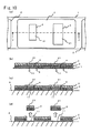
- FIG. 10 is an illustration of a structure of the conventional label having a region for re-application, in which (a) is a plan view, (b) is a cross-sectional view taken along line Y-Y' shown in (a), and (c) and (d) are illustrative views explaining its usage.
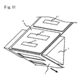
- FIG. 11 is a perspective view explaining an operation of separating a label main body from a strip-shaped backing liner using a release plate in the label having a region for re-application.
- the conventional label having a region for re-application is configured by a strip-shaped backing liner 1 in a shape of a strip and label main bodies 2 each provided with a back surface on which an adhesive 3 is applied.
- the adhesive 3 is applied to the back surface of each label main body 2, and the plurality of label main bodies 2 are temporarily attached to the strip-shaped backing liner 1 at a predetermined interval by the adhesives 3 applied to the back surfaces.
- the cross-sectional view shown in FIG. 10(b) is enlarged in a thickness direction for the sake of explanation.
- Each label main body 2 is provided with regions for re-application 21 each enclosed by a label separation cutting line 4 in a closed state and separable from the label main body 2 such that the regions for re-application 21 can be used, for example, as a return label indicating a destination address for returning and as a tracking label for the courier company.
- the strip-shaped backing liner 1 is provided with re-separation backing regions 11 each enclosed by a backing separation cutting line 5 in a closed state and separable from the strip-shaped backing liner 1 such that each region contains the corresponding region for re-application 21 provided for the label main body 2, that is, each region includes the corresponding region for re-application 21 therein and has an area wider than that of the region for re-application 21.
- the conventional label having a region for re-application as described above is used by separating the back surface of the label main body 2 from the strip-shaped backing liner 1 excluding the re-separation backing regions 11 to expose the adhesive 3, and applying the label main body 2 to which the re-separation backing regions 11 are temporary attached to an object of application 6 by the exposed adhesive 3.
- the regions for re-application 21 can be re-applied to different objects of application by separating the regions for re-application 21 from the re-separation backing regions 11.
- an automatic label separator that mechanically and automatically performs separation using a release plate 7 is used in separating each main body 2 from the strip-shaped backing liner 1 excluding the re-separation backing regions 11.
- Such an automatic label separator separates the label main bodies 2 from the strip-shaped backing liner 1 excluding the re-separation backing regions 11 by, as shown in FIG. 11 , folding back the strip-shaped backing liner 1 using the release plate 7 and transferring only the strip-shaped backing liner 1 toward a downstream side indicated by an arrow.
- the re-separation backing regions 11 are naturally provided in a range wider than the corresponding regions for re-application 21 across the width direction, and a distance between the regions for re-application 21 and a side end becomes narrow.
- this consequently reduces a tensile strength of the strip-shaped backing liner 1 from which the label main bodies 2 have been separated in the transfer direction when using the automatic label separator, there is a problem that the strip-shaped backing liner 1 can be cut up when transferring only the strip-shaped backing liner 1 that has been folded back using the release plate 7 to the downstream side.
- the present invention has been made in view of the above problem, and an object of the present invention is to provide a label having a region for re-application, the label being capable of ensuring a tensile strength of a strip-shaped backing liner from which label main bodies have been separated even when the region for re-application is provided in a wide range across a width direction.
- the re-separation backing partial regions on both ends across the width direction are provided so as to respectively include both end portions of the region for re-application across the width direction.
- a pickable portion enclosed by the label separation cutting line in a closed state is provided continuously from one of the end portions of each region for re-application across the width direction, as a portion from which separation of the corresponding region for re-application starts, and the non-adhesive region is provided so as to slightly extend over the re-separation backing partial regions on both sides in the width direction.
- the label having a region for re-application of the present invention includes label main bodies each provided with a back surface to which an adhesive is applied and the region for re-application defined by a label separation cutting line in a closed state; and a strip-shaped backing liner in a shape of a strip along which the plurality of label main bodies are arranged and temporarily attached at an interval.
- the strip-shaped backing liner is provided with a plurality of re-separation backing partial regions at an interval across a width direction perpendicular to the arrangement direction so as to correspond to the region for re-application defined in each label main body, each re-separation backing partial region being defined by a backing separation cutting line in a closed state and provided over a range wider than the region for re-application in a direction of the arrangement of the label main bodies.
- a region between the adjacent re-separation backing partial regions in the width direction and not temporarily attached in the back surface of the region for re-application is processed as a non-adhesive region.
- the re-separation backing partial regions on both ends across the width direction are provided so as to respectively include both end portions of the region for re-application across the width direction.
- a pickable portion enclosed by the label separation cutting line in a closed state is provided continuously from one of the end portions of each region for re-application across the width direction, as a portion from which separation of the corresponding region for re-application starts.
- the non-adhesive region is provided so as to slightly extend over the re-separation backing partial regions on both sides in the width direction.
- FIG. 1 is plan view illustrating a structure of label having a region for re-application of an embodiment according to the present invention when viewed from a side of a label main body
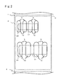
- FIG. 2 is a plan view illustrating the structure of the label having a region for re-application of the embodiment according to the present invention when viewed from a side of a strip-shaped backing liner
- FIG. 3 is a plan view illustrating a structure of a back surface of the label main body shown in FIG. 1
- FIG. 4 is a cross-sectional view taken along line X-X' shown in FIG. 1 .
- the label having a region for re-application of this embodiment is configured by a strip-shaped backing liner 1 in a shape of a strip and label main bodies 2 each provided with a back surface on which an adhesive 3 is applied.
- the adhesive 3 is applied to the back surface of each label main body 2, and the plurality of label main bodies 2 are temporarily attached to the strip-shaped backing liner 1 at a predetermined interval by the adhesives 3 applied to the back surfaces.
- the cross-sectional view shown in FIG. 4 is enlarged in a thickness direction for the sake of explanation. Further, in this embodiment, an up-down direction in each of FIG. 1 to FIG.
- an arrangement direction a direction that is perpendicular to the arrangement direction in FIG. 1 to FIG. 3 is referred to as a width direction.
- Each label main body 2 is provided with two regions for re-application 21 each enclosed by a label separation cutting line 4 in a closed state and separable from the label main body 2, such that the regions for re-application 21 can be used, for example, as a return label indicating a destination address for returning and as a tracking label for a courier company.
- pickable portions 22 each enclosed by the corresponding label separation cutting line 4 in a closed state are provided continuously from the respective regions for re-application 21 on one end thereof across the width direction, as a portion from which separation of the corresponding region for re-application 21 starts. With this, the region for re-application 21 can be easily separated from the pickable portion 22 in the width direction.
- each label separation cutting line 4 is cutting into a part or a whole of a thickness of the label main body 2, and the cutting can be provided for an entire circumference or can be perforations in a regular or a random pattern.
- the regions for re-application 21 and the pickable portions 22 are subjected to a so-called full-cutting or half-cutting process. Further, it is preferable that the label separation cutting line 4 between the pickable portion 22 and the region for re-application 21 be perforations or formed by half-cutting, and that the remaining portion of the label separation cutting line 4 around the pickable portion 22 be formed by full-cutting.
- the pickable portion 22 can be easily picked and the holding portion 22 is continuous from the corresponding region for re-application 21, it is possible to split the holding portion 22 off from the region for re-application 21 after separating the region for re-application 21 while holding the holding portion 22.
- each re-separation backing partial region 12 is provided for the strip-shaped backing liner 1 at an interval across the width direction so as to correspond to each of the two regions for re-application 21 provided on the label main body 2, and each re-separation backing partial region 12 is enclosed by a backing separation cutting line 5 in a closed state.
- Each re-separation backing partial region 12 is provided over a range wider than the corresponding region for re-application 21 in the arrangement direction.
- each backing separation cutting line 5 is cutting through an entire thickness of the strip-shaped backing liner 1 for an entire circumference, and the re-separation backing partial regions 12 are subjected to the so-called full-cutting process.
- regions in each region for re-application 21 to which the re-separation backing partial regions 12 are not temporarily attached and each between the adjacent re-separation backing partial regions 12 in the width direction are processed as non-adhesive regions 31 to which such as silicone is applied so as to bring an effect of an adhesive force of the adhesive 3 to be lost.
- the non-adhesive regions 31 can be wider than the regions for re-application 21 in the arrangement direction or slightly extend over the re-separation backing partial regions 12 on both sides, as shown in FIG.
- the non-adhesive regions 31 at least include the regions in each region for re-application 21 to which the re-separation backing partial regions 12 are not temporarily attached and each between the re-separation backing partial regions 12.
- an area of the non-adhesive regions 31 be as small as possible, as an adhesive force when applying the region for re-application 21 to a different object of application is reduced if this area is large.
- a tensile strength of the strip-shaped backing liner 1 in the arrangement direction is increased as the setting for the number of the re-separation backing partial regions 12 provided in the width direction is decreased, the width of the re-separation backing partial regions 12 is decreased, and a distance between the adjacent re-separation backing partial regions 12 in the width direction is increased.
- the adhesive force when applying the region for re-application 21 to a different object of application is increased as the setting for the number of the re-separation backing partial regions 12 provided in the width direction is increased, the width of the re-separation backing partial regions 12 is increased, and the distance between the adjacent re-separation backing partial regions 12 in the width direction is decreased.
- the strip-shaped backing liner 1 excluding the re-separation backing partial regions 12 in the width direction becomes smaller around a portion at which the re-separation backing partial regions 12 are provided, the tensile strength of the strip-shaped backing liner 1 in the arrangement direction is reduced.
- the number of the re-separation backing partial regions 12 provided in the width direction, the width of the re-separation backing partial regions 12, and the distance between the adjacent re-separation backing partial regions 12 in the width direction be set appropriately according to a tensile strength of the strip-shaped backing liner 1 in the arrangement direction desired to be ensured and an adhesive force desired to be ensured when applying the region for re-application 21 to a different object of application.
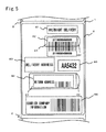
- FIG. 5 is a plan view illustrating an exemplary printing when the label having a region for re-application of the embodiment according to the present invention is used as a courier label
- FIG. 6 is an illustration for explaining the usage of the label having a region for re-application of the embodiment according to the present invention
- FIG. 7 is a perspective view illustrating a state in which the label having a region for re-application of the embodiment according to the present invention are wound in a roll
- FIG. 8 is a side view schematically illustrating a structure of an automatic printing and labeling machine in which the label having a region for re-application of the embodiment according to the present invention is employed
- FIG. 9 is a perspective view illustrating an operation of separating the label main bodies from the strip-shaped backing liner using a release plate in the label having a region for re-application of the embodiment according to the present invention.
- FIG. 5 shows the exemplary printing when the label having a region for re-application of this embodiment is used as a courier label, on which a service indication 81 specifying a delivery service such as a delivery date, a package indication 82 indicating a package number, a delivery destination indication 83 indicating a delivery address, a return address indication 84 indicating a return address, a delivery indication 85 indicating a car number and a route number of a courier company, and a courier company indication 86 indicating a service office number of the courier company, a name, a delivery date, a package number/ total quantity, and other additional information are printed.
- a service indication 81 specifying a delivery service such as a delivery date
- a package indication 82 indicating a package number
- a delivery destination indication 83 indicating a delivery address
- a return address indication 84 indicating a return address
- a delivery indication 85 indicating a car number and a route number of a courier company
- the package indication 82 is printed across one of the two regions for re-application 21 to be re-separated and a region other than the region for re-application 21 that is not to be re-separated, and this region for re-application 21 can be used for providing certification of delivery information, and can be used as a tracking label for the courier company. Further, the return address indication 84 is printed on the other of the regions for re-application 21, and this region for re-application 21 can be used as a return label.
- the adhesive 3 is caused to be exposed by separating the back surface of the label main body 2 from the strip-shaped backing liner 1 excluding the re-separation backing partial regions 12 as shown in FIG. 6(a) , and the label main body 2 while the re-separation backing partial regions 12 being temporarily attached is applied to an object of application 6 by the exposed adhesive 3 as shown in FIG. 6(b) .
- the regions between the adjacent re-separation backing partial regions 12 in the back surfaces of the regions for re-application 21 in the width direction are brought into contact with the object of application 6.
- the regions for re-application 21 are not applied to the object of application 6 at these regions.
- FIG. 7 shows the example of so-called face-in winding in which the label having a region for re-application is wound with the label main bodies 2 facing inside
- face-out winding in which the label having a region for re-application is wound with the label main bodies2 facing outside.
- the automatic printing and labeling machine 90 is provided with a label holding unit 91 that rotatably holds the label having a region for re-application wound into a roll according to this embodiment, a printer-separator unit 92 that carries out printing to the label main body 2 using a thermal print head and separates the label main body 2 after printing from the strip-shaped backing liner 1 using a release plate 7, a backing winding unit 93 that winds the strip-shaped backing liner 1 from which the label main body 2 has been separated, and an applicator unit 95 that applies the label main body 2 separated from the strip-shaped backing liner 1 and fed from the release plate 7 to the object of application 6 such as a package that is transferred on a conveyer 94.
- a printer-separator unit 92 that carries out printing to the label main body 2 using a thermal print head and separates the label main body 2 after printing from the strip-shaped backing liner 1 using a release plate 7, a backing winding unit 93 that winds the strip-shaped backing liner 1 from
- the arrangement direction along which the label main bodies 2 are arranged is a transfer direction, and the printing to the label main body 2 is carried out while the label having a region for re-application fed from the label holding unit 91 is held and transferred between a platen roller of the printer-separator unit 92 and the thermal print head. Further, the strip-shaped backing liner 1 is folded back at a tip of the release plate 7 as shown in FIG. 9 , and the strip-shaped backing liner 1 from which the label main body 2 has been separated is transferred by the backing winding unit 93 toward a downstream side indicated by an arrow shown in FIG. 9 .
- the label main body 2 is separated from the strip-shaped backing liner 1 excluding the re-separation backing partial regions 12, and the label main body 2 separated from the strip-shaped backing liner 1 is fed from the release plate 7 and applied to the object of application 6 by the applicator unit 95.
- the strip-shaped backing liner 1 that is transferred by the backing winding unit 93 is in a state in which, as shown in FIG. 9 , the label main body 2 has been separated and the re-separation backing partial regions 12 have been removed.
- the regions between the adjacent re-separation backing partial regions 12 remain, since the re-separation backing partial regions 12 for temporarily attaching the regions for re-application 21 are provided in the width direction at an interval even when the regions for re-application 21 are provided in a wide range across the width direction. Therefore, it is possible to ensure the tensile strength of the strip-shaped backing liner 1 from which the label main body 2 has been separated in the arrangement direction.
- the region for re-application 21 can be re-applied to a different object of application, as shown in FIG. 6(c) , by separating the region for re-application 21 from the re-separation backing partial regions 12.
- separation of the regions for re-application 21 can be easily carried out in the width direction from the pickable portion 22, which is provided as the portion from which the separation starts and continuously from the regions for re-application 21 in the width direction.
- the non-adhesive regions 31 processed on the back surfaces of the regions for re-application 21 so as to slightly extend over the re-separation backing partial regions 12 on the both sides in the width direction, it is possible to separate the regions for re-application 21 from the re-separation backing partial regions 12 smoothly when separating in the width direction.
- the re-separation backing partial regions 12 on the both ends across the width direction are provided so as to respectively include the both end portions of each region for re-application 21 across the width direction, the adhesive 3 is applied on the back surface of the both end portions of each separated region for re-application 21 in the width direction. Therefore, it is possible to apply the separated region for re-application 21 to a different object of application without causing the both end portions to lift.
- the label main bodies 2 each including the back surface to which the adhesive 3 is applied and the region for re-application 21 defined by the label separation cutting line 4 in a closed state; and the strip-shaped backing liner 1 in a shape of a strip along which the plurality of label main bodies 2 are arranged and temporarily attached at an interval.
- the strip-shaped backing liner 1 is provided with the plurality of re-separation backing partial regions 12 at an interval across the width direction perpendicular to the arrangement direction so as to correspond to the region for re-application 21 defined in each label main body 2, each re-separation backing partial region being defined by the backing separation cutting line 5 in a closed state and provided over the range wider than the region for re-application 21 in the direction of the arrangement of the label main bodies 2.
- the region that is between the adjacent re-separation backing partial regions 12 in the width direction and to which the re-separation backing partial region 12 is not temporarily attached in the back surface of the region for re-application 21 is processed as the non-adhesive region 31.
- the re-separation backing partial regions 12 on the both ends across the width direction are provided so as to respectively include the both end portions of the region for re-application 21 across the width direction.
- the pickable portion 22 enclosed by the label separation cutting line 4 in a closed state is provided continuously from one of the end portions of each region for re-application 21 across the width direction, as the portion from which separation of the corresponding region for re-application 21 starts.
- the non-adhesive region 31 is provided so as to slightly extend over the re-separation backing partial regions 12 on the both sides in the width direction.
Landscapes
- Physics & Mathematics (AREA)
- General Physics & Mathematics (AREA)
- Engineering & Computer Science (AREA)
- Theoretical Computer Science (AREA)
- Making Paper Articles (AREA)
- Labeling Devices (AREA)
- Details Of Rigid Or Semi-Rigid Containers (AREA)
Claims (3)
- Étiquette avec région pour recollage configurée pour être reséparée d'un objet de collage après collage, et recollée sur un objet de collage différent (6), l'étiquette comprenant :des corps principaux d'étiquette (2) munis chacun d'une surface dorsale sur laquelle est appliqué un adhésif (3) et la région de recollage (21) définie par une ligne de découpe de séparation d'étiquettes (4) dans un état fermé ; etun revêtement dorsal en forme de bande (1) se présentant sous la forme d'une bande le long de laquelle la pluralité de corps principaux d'étiquette (2) sont agencés et fixés temporairement selon un certain intervalle, caractérisée en ce quele revêtement dorsal en forme de bande (1) est muni d'une pluralité de régions dorsales partielles de reséparation (12) avec un intervalle dans le sens de la largeur qui est perpendiculaire à la direction d'agencement de façon à correspondre à la région de recollage (21) définie dans chaque corps principal d'étiquette (2), chaque région dorsale partielle de reséparation étant définie par une ligne de découpe de séparation dorsale (5) dans un état fermé et disposée sur une plus large étendue que la région de recollage (21) dans le sens de l'agencement des corps principaux d'étiquette (2),une région située entre les régions dorsales partielles de reséparation adjacentes (12) dans le sens de la largeur et qui n'est pas fixée temporairement à la surface dorsale de la région de recollage (21) est traitée comme une région non adhésive (31), etdes régions non adhésives (31) sont appliquées au dos de l'adhésif (3) à des emplacements situés entre les régions dorsales partielles de reséparation adjacentes (12) dans le sens de la largeur.
- Étiquette avec région pour recollage selon la revendication 1, dans laquelle
les régions dorsales partielles de reséparation (12) sur les deux extrémités dans le sens de la largeur sont disposées de sorte à inclure respectivement les deux parties d'extrémité de la région de recollage (21) dans le sens de la largeur. - Étiquette avec région pour recollage selon l'une des revendications 1 et 2, dans laquelle
une partie saisissable (12) entourée par la ligne de découpe de séparation d'étiquettes (4) dans un état fermé est disposée en continu depuis l'une des parties d'extrémité de chaque région de recollage (21) dans le sens de la largeur, en tant que partie à partir de laquelle commence la séparation de la région pour recollage correspondante (21), et
la région non adhésive (31) est disposée de façon à s'étendre légèrement au-dessus des régions dorsales partielles de reséparation (12) sur les deux côtés dans le sens de la largeur.
Applications Claiming Priority (2)
| Application Number | Priority Date | Filing Date | Title |
|---|---|---|---|
| JP2008251319A JP4856143B2 (ja) | 2008-09-29 | 2008-09-29 | 再貼付用領域付きラベル |
| PCT/JP2008/072485 WO2010035353A1 (fr) | 2008-09-29 | 2008-12-11 | Étiquette avec région pour recollage |
Publications (3)
| Publication Number | Publication Date |
|---|---|
| EP2333752A1 EP2333752A1 (fr) | 2011-06-15 |
| EP2333752A4 EP2333752A4 (fr) | 2012-05-02 |
| EP2333752B1 true EP2333752B1 (fr) | 2014-02-12 |
Family
ID=42059371
Family Applications (1)
| Application Number | Title | Priority Date | Filing Date |
|---|---|---|---|
| EP08877081.3A Not-in-force EP2333752B1 (fr) | 2008-09-29 | 2008-12-11 | Étiquette avec région pour recollage |
Country Status (4)
| Country | Link |
|---|---|
| US (1) | US8507065B2 (fr) |
| EP (1) | EP2333752B1 (fr) |
| JP (1) | JP4856143B2 (fr) |
| WO (1) | WO2010035353A1 (fr) |
Families Citing this family (15)
| Publication number | Priority date | Publication date | Assignee | Title |
|---|---|---|---|---|
| US9061484B2 (en) * | 2006-10-24 | 2015-06-23 | Continental Datalabel, Inc. | Label assembly having registration structures for applying a label to an object |
| AU2012338245B2 (en) * | 2011-11-18 | 2015-09-03 | Sato Holdings Kabushiki Kaisha | Series of wristbands, and wristband |
| US9189978B2 (en) * | 2013-02-27 | 2015-11-17 | Ccl Label, Inc. | Labels, label sheet assemblies, and related methods |
| JP6540034B2 (ja) * | 2015-01-20 | 2019-07-10 | 凸版印刷株式会社 | ラベルテープ及びラベル貼付システム |
| US10056013B1 (en) * | 2016-01-18 | 2018-08-21 | True Label, Inc. | Two-part label with removable strip |
| USD862601S1 (en) | 2016-07-07 | 2019-10-08 | Ccl Label, Inc. | Carrier assembly |
| US20180290416A1 (en) * | 2017-01-20 | 2018-10-11 | Iconex Llc | Single-ply liner label combination and roll |
| US10984683B2 (en) * | 2017-01-20 | 2021-04-20 | Iconex Llc | Two-ply channel liner, label, and roll |
| CA3035388C (fr) | 2018-03-01 | 2026-01-20 | Ccl Label, Inc. | Feuille a perforation d'alimentation |
| EP3774317B8 (fr) * | 2018-04-03 | 2025-10-15 | Iconex LLC | Combinaison support-étiquette monocouche et rouleau |
| USD914085S1 (en) | 2018-08-29 | 2021-03-23 | Ccl Label, Inc. | Label sheet layout assemblies |
| JP7555178B2 (ja) | 2018-09-28 | 2024-09-24 | ブラザー工業株式会社 | 媒体 |
| JP7148888B2 (ja) * | 2018-09-28 | 2022-10-06 | ブラザー工業株式会社 | 媒体 |
| USD943668S1 (en) | 2019-05-01 | 2022-02-15 | Ccl Label, Inc. | Label sheet with surface texture assembly |
| KR102242946B1 (ko) * | 2020-01-19 | 2021-05-04 | 주식회사굿스플로 | 반품 서비스 방법 |
Family Cites Families (11)
| Publication number | Priority date | Publication date | Assignee | Title |
|---|---|---|---|---|
| US4032679A (en) * | 1972-04-27 | 1977-06-28 | Shiro Kojima | Sticker |
| US3914483A (en) * | 1974-02-08 | 1975-10-21 | Bates Printing Specialties Inc | Double die-cut label |
| US4995642A (en) * | 1989-05-08 | 1991-02-26 | Wallace Computer Services, Inc. | Pocket label for shipping package and method of making |
| FR2697206A1 (fr) * | 1992-10-22 | 1994-04-29 | Moore Business Forms Inc | Ensemble de formation d'étiquettes de colisage. |
| US5512343A (en) * | 1994-08-01 | 1996-04-30 | Diagraph Corporation | Label assembly |
| US5958536A (en) * | 1997-03-06 | 1999-09-28 | The Challenge Printing Company | Self-adhesive label with detachable sticker |
| US6410113B1 (en) * | 1999-09-29 | 2002-06-25 | Ncr Corporation | Dual skip label laminate |
| US6368688B1 (en) * | 2000-07-31 | 2002-04-09 | Ward/Kraft, Inc. | Pharmacy form and label |
| JP2002175014A (ja) * | 2000-12-06 | 2002-06-21 | Dainippon Printing Co Ltd | 剥離票付き配送伝票とその製造方法、使用方法 |
| US20040007557A1 (en) * | 2002-07-10 | 2004-01-15 | Maliszewski Diane Shea | Wine bottle label memento |
| JP4723523B2 (ja) * | 2007-02-07 | 2011-07-13 | 株式会社サトー | 配送伝票用ラベル |
-
2008
- 2008-09-29 JP JP2008251319A patent/JP4856143B2/ja not_active Expired - Fee Related
- 2008-12-11 EP EP08877081.3A patent/EP2333752B1/fr not_active Not-in-force
- 2008-12-11 US US13/121,203 patent/US8507065B2/en not_active Expired - Fee Related
- 2008-12-11 WO PCT/JP2008/072485 patent/WO2010035353A1/fr not_active Ceased
Also Published As
| Publication number | Publication date |
|---|---|
| EP2333752A4 (fr) | 2012-05-02 |
| US8507065B2 (en) | 2013-08-13 |
| JP2010085451A (ja) | 2010-04-15 |
| WO2010035353A1 (fr) | 2010-04-01 |
| JP4856143B2 (ja) | 2012-01-18 |
| US20110177277A1 (en) | 2011-07-21 |
| EP2333752A1 (fr) | 2011-06-15 |
Similar Documents
| Publication | Publication Date | Title |
|---|---|---|
| EP2333752B1 (fr) | Étiquette avec région pour recollage | |
| EP2317491B1 (fr) | Étiquette de prix et procédé pour son application | |
| JP4781293B2 (ja) | ラベルシート | |
| JPH04232986A (ja) | 接着ラベルのクラスタ | |
| US7850207B1 (en) | Multi-part labels with variable data on at least two layers | |
| US20200086672A1 (en) | System and method of manufacturing extended content labels | |
| JP2012006184A (ja) | 熨斗付き配送伝票 | |
| JP2009157030A (ja) | ラベル連続体、その剥離方法および剥離装置 | |
| EP3571041B1 (fr) | Doublure de canal à deux plis, étiquette et rouleau | |
| JP4430097B2 (ja) | Rfidラベルおよびその製造方法 | |
| JP2009193262A (ja) | Rfidタグ | |
| US20180290416A1 (en) | Single-ply liner label combination and roll | |
| JP2007232766A (ja) | Rfidラベル | |
| JP4559845B2 (ja) | カス剥離装置 | |
| JP4750569B2 (ja) | ラベル連続体 | |
| EP3774317B1 (fr) | Combinaison support-étiquette monocouche et rouleau | |
| JPH09327872A (ja) | 台紙なしラベルの製造方法 | |
| JP4914230B2 (ja) | 配送伝票用ラベル | |
| JP2008151881A (ja) | 多層ラベル | |
| JP4878892B2 (ja) | 小型粘着ラベルシート | |
| JP2005331646A (ja) | Icラベルおよびicラベルの製造方法 | |
| JP3942886B2 (ja) | 荷札ラベル | |
| JP4986227B2 (ja) | ラベル貼付装置 | |
| JPH0740476A (ja) | 単位ラベル用紙の作成方法 | |
| JP2014138986A (ja) | ラベル処理装置 |
Legal Events
| Date | Code | Title | Description |
|---|---|---|---|
| PUAI | Public reference made under article 153(3) epc to a published international application that has entered the european phase |
Free format text: ORIGINAL CODE: 0009012 |
|
| 17P | Request for examination filed |
Effective date: 20101207 |
|
| AK | Designated contracting states |
Kind code of ref document: A1 Designated state(s): AT BE BG CH CY CZ DE DK EE ES FI FR GB GR HR HU IE IS IT LI LT LU LV MC MT NL NO PL PT RO SE SI SK TR |
|
| AX | Request for extension of the european patent |
Extension state: AL BA MK RS |
|
| DAX | Request for extension of the european patent (deleted) | ||
| A4 | Supplementary search report drawn up and despatched |
Effective date: 20120329 |
|
| RIC1 | Information provided on ipc code assigned before grant |
Ipc: B42D 15/04 20060101ALI20120323BHEP Ipc: B42D 11/00 20060101ALI20120323BHEP Ipc: G09F 3/10 20060101AFI20120323BHEP Ipc: B65C 9/18 20060101ALI20120323BHEP Ipc: G09F 3/02 20060101ALI20120323BHEP |
|
| GRAP | Despatch of communication of intention to grant a patent |
Free format text: ORIGINAL CODE: EPIDOSNIGR1 |
|
| INTG | Intention to grant announced |
Effective date: 20130712 |
|
| GRAS | Grant fee paid |
Free format text: ORIGINAL CODE: EPIDOSNIGR3 |
|
| RAP1 | Party data changed (applicant data changed or rights of an application transferred) |
Owner name: SATO HOLDINGS KABUSHIKI KAISHA |
|
| GRAA | (expected) grant |
Free format text: ORIGINAL CODE: 0009210 |
|
| AK | Designated contracting states |
Kind code of ref document: B1 Designated state(s): AT BE BG CH CY CZ DE DK EE ES FI FR GB GR HR HU IE IS IT LI LT LU LV MC MT NL NO PL PT RO SE SI SK TR |
|
| REG | Reference to a national code |
Ref country code: GB Ref legal event code: FG4D |
|
| REG | Reference to a national code |
Ref country code: CH Ref legal event code: EP |
|
| REG | Reference to a national code |
Ref country code: AT Ref legal event code: REF Ref document number: 652438 Country of ref document: AT Kind code of ref document: T Effective date: 20140215 |
|
| REG | Reference to a national code |
Ref country code: IE Ref legal event code: FG4D |
|
| REG | Reference to a national code |
Ref country code: DE Ref legal event code: R096 Ref document number: 602008030322 Country of ref document: DE Effective date: 20140403 |
|
| REG | Reference to a national code |
Ref country code: NL Ref legal event code: VDEP Effective date: 20140212 |
|
| REG | Reference to a national code |
Ref country code: AT Ref legal event code: MK05 Ref document number: 652438 Country of ref document: AT Kind code of ref document: T Effective date: 20140212 |
|
| REG | Reference to a national code |
Ref country code: LT Ref legal event code: MG4D |
|
| PG25 | Lapsed in a contracting state [announced via postgrant information from national office to epo] |
Ref country code: LT Free format text: LAPSE BECAUSE OF FAILURE TO SUBMIT A TRANSLATION OF THE DESCRIPTION OR TO PAY THE FEE WITHIN THE PRESCRIBED TIME-LIMIT Effective date: 20140212 Ref country code: NO Free format text: LAPSE BECAUSE OF FAILURE TO SUBMIT A TRANSLATION OF THE DESCRIPTION OR TO PAY THE FEE WITHIN THE PRESCRIBED TIME-LIMIT Effective date: 20140512 Ref country code: IS Free format text: LAPSE BECAUSE OF FAILURE TO SUBMIT A TRANSLATION OF THE DESCRIPTION OR TO PAY THE FEE WITHIN THE PRESCRIBED TIME-LIMIT Effective date: 20140612 |
|
| PG25 | Lapsed in a contracting state [announced via postgrant information from national office to epo] |
Ref country code: NL Free format text: LAPSE BECAUSE OF FAILURE TO SUBMIT A TRANSLATION OF THE DESCRIPTION OR TO PAY THE FEE WITHIN THE PRESCRIBED TIME-LIMIT Effective date: 20140212 Ref country code: CY Free format text: LAPSE BECAUSE OF FAILURE TO SUBMIT A TRANSLATION OF THE DESCRIPTION OR TO PAY THE FEE WITHIN THE PRESCRIBED TIME-LIMIT Effective date: 20140212 Ref country code: AT Free format text: LAPSE BECAUSE OF FAILURE TO SUBMIT A TRANSLATION OF THE DESCRIPTION OR TO PAY THE FEE WITHIN THE PRESCRIBED TIME-LIMIT Effective date: 20140212 Ref country code: FI Free format text: LAPSE BECAUSE OF FAILURE TO SUBMIT A TRANSLATION OF THE DESCRIPTION OR TO PAY THE FEE WITHIN THE PRESCRIBED TIME-LIMIT Effective date: 20140212 Ref country code: ES Free format text: LAPSE BECAUSE OF FAILURE TO SUBMIT A TRANSLATION OF THE DESCRIPTION OR TO PAY THE FEE WITHIN THE PRESCRIBED TIME-LIMIT Effective date: 20140212 Ref country code: SE Free format text: LAPSE BECAUSE OF FAILURE TO SUBMIT A TRANSLATION OF THE DESCRIPTION OR TO PAY THE FEE WITHIN THE PRESCRIBED TIME-LIMIT Effective date: 20140212 Ref country code: PT Free format text: LAPSE BECAUSE OF FAILURE TO SUBMIT A TRANSLATION OF THE DESCRIPTION OR TO PAY THE FEE WITHIN THE PRESCRIBED TIME-LIMIT Effective date: 20140612 |
|
| PG25 | Lapsed in a contracting state [announced via postgrant information from national office to epo] |
Ref country code: BE Free format text: LAPSE BECAUSE OF FAILURE TO SUBMIT A TRANSLATION OF THE DESCRIPTION OR TO PAY THE FEE WITHIN THE PRESCRIBED TIME-LIMIT Effective date: 20140212 Ref country code: LV Free format text: LAPSE BECAUSE OF FAILURE TO SUBMIT A TRANSLATION OF THE DESCRIPTION OR TO PAY THE FEE WITHIN THE PRESCRIBED TIME-LIMIT Effective date: 20140212 Ref country code: HR Free format text: LAPSE BECAUSE OF FAILURE TO SUBMIT A TRANSLATION OF THE DESCRIPTION OR TO PAY THE FEE WITHIN THE PRESCRIBED TIME-LIMIT Effective date: 20140212 |
|
| PG25 | Lapsed in a contracting state [announced via postgrant information from national office to epo] |
Ref country code: EE Free format text: LAPSE BECAUSE OF FAILURE TO SUBMIT A TRANSLATION OF THE DESCRIPTION OR TO PAY THE FEE WITHIN THE PRESCRIBED TIME-LIMIT Effective date: 20140212 Ref country code: DK Free format text: LAPSE BECAUSE OF FAILURE TO SUBMIT A TRANSLATION OF THE DESCRIPTION OR TO PAY THE FEE WITHIN THE PRESCRIBED TIME-LIMIT Effective date: 20140212 Ref country code: RO Free format text: LAPSE BECAUSE OF FAILURE TO SUBMIT A TRANSLATION OF THE DESCRIPTION OR TO PAY THE FEE WITHIN THE PRESCRIBED TIME-LIMIT Effective date: 20140212 Ref country code: CZ Free format text: LAPSE BECAUSE OF FAILURE TO SUBMIT A TRANSLATION OF THE DESCRIPTION OR TO PAY THE FEE WITHIN THE PRESCRIBED TIME-LIMIT Effective date: 20140212 |
|
| REG | Reference to a national code |
Ref country code: DE Ref legal event code: R097 Ref document number: 602008030322 Country of ref document: DE |
|
| PG25 | Lapsed in a contracting state [announced via postgrant information from national office to epo] |
Ref country code: PL Free format text: LAPSE BECAUSE OF FAILURE TO SUBMIT A TRANSLATION OF THE DESCRIPTION OR TO PAY THE FEE WITHIN THE PRESCRIBED TIME-LIMIT Effective date: 20140212 Ref country code: SK Free format text: LAPSE BECAUSE OF FAILURE TO SUBMIT A TRANSLATION OF THE DESCRIPTION OR TO PAY THE FEE WITHIN THE PRESCRIBED TIME-LIMIT Effective date: 20140212 |
|
| PLBE | No opposition filed within time limit |
Free format text: ORIGINAL CODE: 0009261 |
|
| STAA | Information on the status of an ep patent application or granted ep patent |
Free format text: STATUS: NO OPPOSITION FILED WITHIN TIME LIMIT |
|
| 26N | No opposition filed |
Effective date: 20141113 |
|
| REG | Reference to a national code |
Ref country code: DE Ref legal event code: R097 Ref document number: 602008030322 Country of ref document: DE Effective date: 20141113 |
|
| PG25 | Lapsed in a contracting state [announced via postgrant information from national office to epo] |
Ref country code: IT Free format text: LAPSE BECAUSE OF FAILURE TO SUBMIT A TRANSLATION OF THE DESCRIPTION OR TO PAY THE FEE WITHIN THE PRESCRIBED TIME-LIMIT Effective date: 20140212 |
|
| PG25 | Lapsed in a contracting state [announced via postgrant information from national office to epo] |
Ref country code: SI Free format text: LAPSE BECAUSE OF FAILURE TO SUBMIT A TRANSLATION OF THE DESCRIPTION OR TO PAY THE FEE WITHIN THE PRESCRIBED TIME-LIMIT Effective date: 20140212 |
|
| PG25 | Lapsed in a contracting state [announced via postgrant information from national office to epo] |
Ref country code: LU Free format text: LAPSE BECAUSE OF FAILURE TO SUBMIT A TRANSLATION OF THE DESCRIPTION OR TO PAY THE FEE WITHIN THE PRESCRIBED TIME-LIMIT Effective date: 20141211 |
|
| REG | Reference to a national code |
Ref country code: CH Ref legal event code: PL |
|
| REG | Reference to a national code |
Ref country code: IE Ref legal event code: MM4A |
|
| PG25 | Lapsed in a contracting state [announced via postgrant information from national office to epo] |
Ref country code: CH Free format text: LAPSE BECAUSE OF NON-PAYMENT OF DUE FEES Effective date: 20141231 Ref country code: LI Free format text: LAPSE BECAUSE OF NON-PAYMENT OF DUE FEES Effective date: 20141231 Ref country code: IE Free format text: LAPSE BECAUSE OF NON-PAYMENT OF DUE FEES Effective date: 20141211 |
|
| REG | Reference to a national code |
Ref country code: FR Ref legal event code: PLFP Year of fee payment: 8 |
|
| PG25 | Lapsed in a contracting state [announced via postgrant information from national office to epo] |
Ref country code: BG Free format text: LAPSE BECAUSE OF FAILURE TO SUBMIT A TRANSLATION OF THE DESCRIPTION OR TO PAY THE FEE WITHIN THE PRESCRIBED TIME-LIMIT Effective date: 20140212 Ref country code: MC Free format text: LAPSE BECAUSE OF FAILURE TO SUBMIT A TRANSLATION OF THE DESCRIPTION OR TO PAY THE FEE WITHIN THE PRESCRIBED TIME-LIMIT Effective date: 20140212 |
|
| PG25 | Lapsed in a contracting state [announced via postgrant information from national office to epo] |
Ref country code: GR Free format text: LAPSE BECAUSE OF FAILURE TO SUBMIT A TRANSLATION OF THE DESCRIPTION OR TO PAY THE FEE WITHIN THE PRESCRIBED TIME-LIMIT Effective date: 20140513 |
|
| PG25 | Lapsed in a contracting state [announced via postgrant information from national office to epo] |
Ref country code: MT Free format text: LAPSE BECAUSE OF FAILURE TO SUBMIT A TRANSLATION OF THE DESCRIPTION OR TO PAY THE FEE WITHIN THE PRESCRIBED TIME-LIMIT Effective date: 20140212 Ref country code: HU Free format text: LAPSE BECAUSE OF FAILURE TO SUBMIT A TRANSLATION OF THE DESCRIPTION OR TO PAY THE FEE WITHIN THE PRESCRIBED TIME-LIMIT; INVALID AB INITIO Effective date: 20081211 Ref country code: TR Free format text: LAPSE BECAUSE OF FAILURE TO SUBMIT A TRANSLATION OF THE DESCRIPTION OR TO PAY THE FEE WITHIN THE PRESCRIBED TIME-LIMIT Effective date: 20140212 |
|
| REG | Reference to a national code |
Ref country code: FR Ref legal event code: PLFP Year of fee payment: 9 |
|
| REG | Reference to a national code |
Ref country code: FR Ref legal event code: PLFP Year of fee payment: 10 |
|
| P01 | Opt-out of the competence of the unified patent court (upc) registered |
Effective date: 20230413 |
|
| PGFP | Annual fee paid to national office [announced via postgrant information from national office to epo] |
Ref country code: GB Payment date: 20231220 Year of fee payment: 16 |
|
| PGFP | Annual fee paid to national office [announced via postgrant information from national office to epo] |
Ref country code: FR Payment date: 20231221 Year of fee payment: 16 Ref country code: DE Payment date: 20231214 Year of fee payment: 16 |
|
| REG | Reference to a national code |
Ref country code: DE Ref legal event code: R119 Ref document number: 602008030322 Country of ref document: DE |
|
| GBPC | Gb: european patent ceased through non-payment of renewal fee |
Effective date: 20241211 |
|
| PG25 | Lapsed in a contracting state [announced via postgrant information from national office to epo] |
Ref country code: DE Free format text: LAPSE BECAUSE OF NON-PAYMENT OF DUE FEES Effective date: 20250701 |
|
| PG25 | Lapsed in a contracting state [announced via postgrant information from national office to epo] |
Ref country code: GB Free format text: LAPSE BECAUSE OF NON-PAYMENT OF DUE FEES Effective date: 20241211 |
|
| PG25 | Lapsed in a contracting state [announced via postgrant information from national office to epo] |
Ref country code: FR Free format text: LAPSE BECAUSE OF NON-PAYMENT OF DUE FEES Effective date: 20241231 |