EP2333786B1 - Diaphragme à fente asymétrique ainsi que dispositif et procédé de sa fabrication - Google Patents
Diaphragme à fente asymétrique ainsi que dispositif et procédé de sa fabrication Download PDFInfo
- Publication number
- EP2333786B1 EP2333786B1 EP09178329A EP09178329A EP2333786B1 EP 2333786 B1 EP2333786 B1 EP 2333786B1 EP 09178329 A EP09178329 A EP 09178329A EP 09178329 A EP09178329 A EP 09178329A EP 2333786 B1 EP2333786 B1 EP 2333786B1
- Authority
- EP
- European Patent Office
- Prior art keywords
- axis
- rotational axis
- movement
- workpiece
- rotational
- Prior art date
- Legal status (The legal status is an assumption and is not a legal conclusion. Google has not performed a legal analysis and makes no representation as to the accuracy of the status listed.)
- Not-in-force
Links
Images




Classifications
-
- G—PHYSICS
- G21—NUCLEAR PHYSICS; NUCLEAR ENGINEERING
- G21K—HANDLING OF PARTICLES OR IONISING RADIATION NOT OTHERWISE PROVIDED FOR; IRRADIATION DEVICES; GAMMA RAY OR X-RAY MICROSCOPES
- G21K1/00—Arrangements for handling particles or ionising radiation, e.g. focusing or moderating
- G21K1/02—Arrangements for handling particles or ionising radiation, e.g. focusing or moderating using diaphragms, collimators
-
- G—PHYSICS
- G21—NUCLEAR PHYSICS; NUCLEAR ENGINEERING
- G21K—HANDLING OF PARTICLES OR IONISING RADIATION NOT OTHERWISE PROVIDED FOR; IRRADIATION DEVICES; GAMMA RAY OR X-RAY MICROSCOPES
- G21K2207/00—Particular details of imaging devices or methods using ionizing electromagnetic radiation such as X-rays or gamma rays
Definitions
- the invention relates to a slit diaphragm, in particular an asymmetrical slit diaphragm with extended opening angle for imaging radiating and backscattering objects, according to the preamble of claim 1, and an apparatus and a method for producing the same, according to the preambles of claims 8 and 13.
- the radiation source can be, for example, the effective focal spot on the anode of an x-ray tube or surface-distributed radiating material.
- the latter can be radioactive waste distributed over a room in a collecting bin, whereby alleged discrepancies between declaration and actual content must be clarified.
- Further examples of radiation sources whose shape one wishes to image are deposits with uranium-containing ores or nuclear facilities, in which it is often of importance not only to determine the nature of the radiation, but also to determine the spatial structure of the radiation sources.
- the thickness of the material for the pinhole diaphragm must be large, that is to say in relation to the half-value thickness of the intensity of the radiation used for imaging. Therefore, the achievable image quality is essentially determined by aperture diameter and material thickness and density. Often, therefore, one obtains at best a shadow image of the actual pinhole, wherein the pinhole, which is to serve for imaging, due to the wall thickness becomes a collimator, which can pass only a straight-line beam. Therefore, the aperture in the hole cameras is often trumpet-shaped with the narrow spot to the radiation source designed so as not to lose the imaging properties completely. In the case of high-energy radiation, the solutions known from the prior art have a considerable deviation from the ideal hole-camera principle due to the required material thickness.
- the aperture can be realized with almost any material thickness without losing its imaging properties.
- the diaphragm is suitable for limiting radiation originating from a radiation source, in particular high-energy radiation, and for directing it to an imaging region along an optical axis x according to the hole-camera principle.
- the camera body is unwieldy and heavy; including the shield, the camera assembly typically weighs 200 to 300 kg.
- Another disadvantage is the long exposure time; In particular when imaging backscattering objects, an exposure time of more than half an hour may be required due to the low intensity of the backscatter radiation.
- the object of the invention is therefore to provide a slit diaphragm for a pinhole camera, which compared to that in the patent DE 10 2005 029 674 B4 disclosed aperture a more compact camera design and a higher intensity on the imaging surface and thus allows a shorter exposure time.
- the object area to be imaged should be retained.
- the object is achieved by means of a slit diaphragm, in particular an asymmetrical slit diaphragm with extended opening angle for imaging radiating and backscattering objects, with the features mentioned in claim 1.
- An absorption element here is to be understood as an element which has at least one region which at least partially absorbs the radiation.
- a gap is to be understood as meaning a region which absorbs the radiation to a small extent. It may be filled with air or other suitable material which absorbs the radiation less than the portions of the absorption elements at least partially absorbing the radiation, which material may be in the form of a separate insert or a coating applied to at least one of the non-planar surfaces ,
- a ruled surface is an area in which there is a straight line at every point on the surface that lies completely within the surface. These completely in-plane straight lines are referred to as the generators of the control surface.
- the Gaussian curvature of a surface at a point is the product of its two main features in the point; the principal curvatures of the area at a point are the minimum value and the maximum value of the curvatures of all curves resulting from intersecting the area with a plane containing the surface normal on the point.
- the camera structure In order to increase the intensity on the imaging surface, the camera structure is to be brought closer to the object. Both the downsizing of the camera body and the closer approach to the object require an enlargement of the viewing angle. This becomes all the more necessary when small-area semiconductor-based flat panel detectors are to be used. These have the advantage of not only converting the image directly into digital signals, but also being available with very high sensitivity.
- the enlargement of the viewing angle requires a corresponding adaptation of the diaphragm geometry in order to achieve a fan-shaped beam guidance.
- a fan-shaped beam guide was also in the published patent application DE 10 2005 048 519 A1 revealed focal point oriented roller blind used. However, this is not based on the Lochtrekar, but directed in each position only one beam to the detector located in a focal point; a two-dimensional image is obtained only by turning the roller shutter and line by line scanning of the object.
- the slit diaphragm according to the invention suitable to limit radiation emitted by a radiation source, in particular high-energy radiation and directed along an optical axis according to the Lochensekar on an imaging area, and comprises a first absorption element, which has a first non-planar outer surface of the at least one subregion lies on a control surface whose Gaussian curvature does not disappear in the subregion, and a second absorption element which has a second non-planar outer surface whose surface contour is at least partially complementary to the non-planar outer surface of the first absorption element is, wherein the two absorption elements are positioned or positioned so that between the two non-planar outer surfaces, a gap is present.
- the diaphragm according to the invention is further characterized in that the distance in a direction perpendicular to the optical axis between the generatrices of the control surface decreases towards the imaging region. This ensures that the approximately along the generatrix of the control surface incident beam converge almost unhindered through the aperture, converge behind the aperture and meet as close to the aperture on an imaging range, which can be significantly smaller than the diaphragm body. It is preferred that, at least in a partial region of the first non-planar outer surface, the distance between the generatrices of the control surface and the imaging region decreases in each direction perpendicular to the optical axis. It is thereby achieved that the radiation bundles incident approximately along the generatrix of the control surface converge particularly strongly towards the imaging region.
- the mapping rule is simplified, and with a suitable position of the diaphragm body, the area around the central axis can be used as the imaging area.
- the diaphragm can be produced by means of a device according to claim 9 or a method according to claim 14.
- the polar angles of the direction vectors of the generatrix of the control surface with respect to the central axis are linearly related to the intersection of the generatrix of the control surface with the central axis. This ensures that the mapping rule is approximately linear and the diaphragm can be produced by means of a device according to claim 10 or a method according to claim 15.
- the set of all ruled surfaces in which the polar angles of the direction vectors of the generators of the ruled surface with respect to the central axis are not constantly linearly related to the intersection of the generatrices of the ruled surface with the central axis is a subset of the ruled surfaces whose Gaussian curvature does not disappear anywhere; that is, the feature that the polar angles of the direction vectors of the generatrix of the control surface with respect to the central axis in non-constant linear relationship with the intersection of the generatrix of the control surface with the central axis, resulting in a slit diaphragm according to the invention, without the additional requirement that the Gaussian curvature the ruled surface disappears nowhere.
- the central axis is outside the diaphragm body. This ensures that the detector can be arranged in the vicinity of the central axis, so that an image can be recorded on the smallest possible area.
- the absorption elements have a trapezoidal plan, which widens towards the radiation source. This ensures that the outer shape of the absorption elements corresponds to the area used for the fan-shaped beam guidance.
- the opening of the gap on the radiation source facing side of the slit is greater than the opening of the gap on the imaging region side facing the slit. This ensures that the beams passing through the gap also converge in the direction perpendicular to the gap.
- the slit diaphragm comprises, in addition to the one gap, at least one further gap, the shape of which in each case results essentially from an affine image from the shape of the one gap, as in German Patent Application No. 10 2008 025 109.7-54 described in more detail.
- An affine image is an image of the three-dimensional space on itself, which maps each straight line to a straight line.
- EP 2 062 705 A1 discloses an apparatus and a method for producing slit diaphragms, with which in the patent DE 10 2005 029 674 B4 disclosed slit diaphragm and in the published patent application DE 10 2005 048 519 A1 revealed focal point-oriented roller blind can be produced. It is a further object of the present invention to further develop this teaching in order to provide an apparatus and a method for producing a slit diaphragm according to the invention.
- this object is achieved by means of a device and a method for producing a slit diaphragm according to the features mentioned in claim 8 or claim 13.
- the apparatus for producing a slit includes a cutting tool adapted to cut along a straight line, and means adapted to effect relative movement between the cutting tool and a workpiece such that the cutting tool passes along the workpiece a line which corresponds to a beam path in the slit diaphragm to be produced.
- the cutting tool is adapted to cut along a first direction.
- the means comprise a holding element, on which a workpiece can be fastened and which is rotatably mounted about a first axis of rotation.
- the means are adapted to effect a first rotational movement of the retaining element about the first axis of rotation and at the same time a translational movement of the retaining element along the first axis of rotation.
- the first rotational movement and the translational movement of the retaining element are coupled.
- This teaching is further developed by the present invention in that the means are further adapted to effect a second rotational movement of the holding member and the first axis of rotation about a second axis of rotation simultaneously with the first rotational movement and the translational movement, and the second rotational movement and translational movement of the retaining element are coupled. It is thereby achieved that the distance in the direction of the first axis of rotation between the cut beam paths decreases in the direction perpendicular to the first and second axes of rotation.
- the first axis of rotation, the second axis of rotation and the line along which the cutting tool cuts have a common point of intersection.
- the slit diaphragm produced by means of the device has the advantageous additional feature of claim 2.
- the second axis of rotation is perpendicular to the cutting direction of the cutting tool and perpendicular to the first axis of rotation.
- the translational movement and the first rotational movement are linearly coupled and the translational movement and the second rotational movement are linearly coupled. Such a linear coupling can be accomplished with particularly simple technical means.
- the slit diaphragm produced by means of the device has the advantageous additional feature of claim 3.
- the cutting tool is arranged immovably. It is thus preferred that the cutting tool is stationary and the workpiece is guided around it.
- the starting point of this preferred embodiment is not to clamp the workpiece in a fixed support and to guide the tool, but conversely to move it in a controlled manner around a milling cutter or a cutting jet.
- the means may comprise a first, a second and a third threaded shaft, wherein the first threaded shaft is parallel to the first axis of rotation, the second threaded shaft is located on the first axis of rotation and the third threaded shaft is located on the second axis of rotation.
- a rotational movement of the three threaded shafts may be coupled by a gear system.
- the first screw shaft may include a portion formed as a screw shaft through which a support arm to which the second screw shaft is connected is movable along the first rotation axis.
- a relative movement between a cutting tool which is suitable for cutting along a straight line and a workpiece is carried out such that the cutting tool cuts the workpiece along a line corresponding to a beam path in the plane a first rotational movement of the workpiece about a first axis of rotation and simultaneously a translational movement of the workpiece along the first axis of rotation is performed and the first rotational movement and the translational movement of the workpiece are coupled.
- This teaching is further developed by the present invention such that a second rotational movement of the workpiece and the first axis of rotation about a second axis of rotation is carried out simultaneously with the first rotational movement and the translation movement and the second rotational movement and the translational movement of the workpiece are coupled.
- the first axis of rotation, the second axis of rotation and the line along which the cutting tool cuts have a common point of intersection. It is thereby achieved that the slit diaphragm produced by the method has the advantageous additional feature of claim 2. It is particularly preferred that the second axis of rotation is perpendicular to the cutting direction of the cutting tool and perpendicular to the first axis of rotation. It is also particularly preferred that the translational movement and the first rotational movement are linearly coupled and the translational movement and the second rotational movement are linearly coupled. Such a linear coupling can be accomplished with particularly simple technical means. Furthermore, it is achieved that the slit diaphragm produced by the method has the advantageous additional feature of claim 3.
- any method known in the art may be used, including, for example, milling, fine milling, precision milling, blasting, jet milling or sawing.
- FIG. 1 illustrates the Lochtreradaferat an imaging device 100.
- a radiation source 102 for example, a test body
- high-energy radiation 104 in particular X-rays or gamma rays
- the radiation 104 strikes a diaphragm 110, by which it is delimited and directed along an optical axis x according to the hole-camera principle onto an imaging region 106.
- the imaging region 106 is typically a projection surface on which an image of the test body 102 is created.
- a receiving unit 108 which is sensitive to the radiation 104, in particular a detector or a camera.
- FIG. 2 shows schematically a test arrangement.
- a continuously radiating, powerful x-ray tube 112 generates radiation, which is masked out by an all-round shield, here a lead wall 114 with window.
- the radiation passing through the window of the lead wall 114 is incident on an aluminum plate as scatter filter 116.
- the actual test object 118 is arranged between the scatter filter 116 and the diaphragm 120 according to the invention, which is integrated in a shielding wall 122 made of lead.
- an X-ray film or an image-forming film (English: phosphor imaging plate) in a cassette serves as the detector 124 on the projection surface 126.
- the invention is not limited to this arrangement.
- the invention can also be used for imaging backscattered radiation, for example for radiographic examination of objects for which only one-sided access is possible.
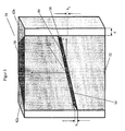
- FIG. 3 shows a perspective view of a first embodiment of a slit 50 according to the invention according to claim 3.
- the slit 50 comprises a first absorption element 52 having a first non-planar outer surface 54 and a second Absorption member 56 having a second non-planar outer surface 58. Between the two non-planar outer surfaces 54 and 58 is a gap 60.
- the absorption elements have a trapezoidal plan, which widens towards the radiation source; the lateral brackets 62a and 62b have a corresponding complementary shape.
- first non-planar outer surface 54 is in FIG. 3 drawn a Cartesian coordinate system, whose origin lies at the center of the first non-planar outer surface 54, the x- axis lies in the direction of the optical axis and the ⁇ -axis lies on the central axis through which all generators of the control surface on which the first not -plane outer surface 54 is, run.
- the imaging area is behind the aperture 50 in the direction of the positive x-axis.
- the height h 1 of the opening of the gap 60 at the front of the aperture 50 is greater than the height h 2 of the opening of the gap 60 at the back of the aperture 50.
- the height h 1 can be 3 mm and the height h 2 1 mm .
- the rear opening of the gap is steeper than the front opening of the gap due to the fan-shaped beam guide.
- the width d of the front side of a lateral support may for example be 10 to 25 mm.
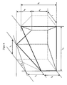
- FIG. 4 shows an exploded view of in FIG. 3 shown slit diaphragm according to the invention.
- two generators E 1 and E 2 of the control surface are drawn.
- the portion of the generatrix E 2 extending on the first non-planar outer surface 54 is highlighted for clarity.
- the distance in the y-direction, ie in the direction of the central axis, between the generatrices E 1 and E 2 decreases towards the imaging region.
- the distance between the generatrix of the control surface in the z-direction, and thus in each direction perpendicular to the optical axis also decreases towards the imaging region.
- FIG. 6 shows a perspective view of a second embodiment of a slit 70 according to the invention.
- the slit 70 comprises a first absorption element 72 with a first non-planar outer surface and a second absorption element 76th with a second non-planar outer surface.
- first absorption element 72 with a first non-planar outer surface
- second absorption element 76th with a second non-planar outer surface.
- the gap 80 is shown, not the complementary non-planar outer surfaces forming it, which are close together.
- a slit 70 ' according to the patent DE 10 2005 029 674 B4 drawn with a first absorption element 72 ', a second absorption element 76' and a gap 80 ', wherein both diaphragms have the same central axis and are described in the same Cartesian coordinate system whose ⁇ -axis lies on the common central axis.
- the absorption elements of the slit diaphragm of the second exemplary embodiment have a trapezoidal plan view.
- the lines of intersection of the gaps with the outer boundary surfaces of the respective slit are shown, namely in each case the two outermost generatrices E 3 and E 4 or E 3 'and E 4 ', the opening of the slit on the side of the slit diaphragm, O 1, facing the radiation source or O 1 ', and the opening of the gap on the imaging region side facing the slit, O 2 and O 2 '.
- the generatrices of the control surface, on which the first non-planar outer surface of the first absorption element of the slit diaphragm of the second embodiment lies, converge in the y-direction, ie in the direction of the central axis. Also, their z-coordinates approach each other in the range x ⁇ 0, in which the first non-planar outer surface lies.
- the distance between the generatrix of the control surface and the imaging region decreases in each direction perpendicular to the optical axis.
- the ⁇ -axis is outside the diaphragm body.
- the detector can be arranged in the vicinity of the gamma axis at a small distance from the slit diaphragm on a particularly small area.
- Such asymmetric design of the visor body has already been in the German patent application with the file number 10 2008 025 109.7-54 disclosed; However, in the present invention, not only the diaphragm body but also the (unlimited) control surface is asymmetrical with respect to the ⁇ -axis.
- FIG. 7 shows a perspective view of a third embodiment of a slit 90 according to the invention, in which, as in the German patent application with the file reference 10 2008 025 109.7-54 described in more detail, in addition to the gap 92, a further gap 94 is arranged, the shape of which results from an affine image of the shape of the gap 92.
- the affine mapping is a rotation about the central axis y about the angle ⁇ .
- the angle ⁇ influences both the intensity distribution in the image field as well as the width of the reproduced image; he can be chosen freely. If required, additional columns can be added.
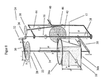
- FIG. 8 shows a perspective view of an inventive apparatus for beam milling a slit of cube-shaped raw material (semi-finished) with half-milled block.
- This device is suitable for manufacturing a slit diaphragm according to claim 3.
- the drawn Cartesian coordinate system is to be understood as a body-fixed on the workpiece 10 related; it corresponds to the in the Figures 3 . 4 and 6 drawn Cartesian coordinate systems.
- a first threaded shaft 16 is driven, which runs parallel to the ⁇ -axis.
- the first threaded shaft 16 has a portion 18 which is formed as a worm shaft.
- a holding arm 20 arranged parallel to the z axis is moved in a direction parallel to the ⁇ axis, whereby a second threaded shaft 22 connected to the holding arm 20 and arranged along the ⁇ axis and the workpiece 10 arranged thereon is moved linearly along the ⁇ -axis.
- the device comprises a third threaded shaft 40, which runs along the z-axis.
- the rotation of the three threaded shafts 16, 22 and 40 is synchronized, wherein the mechanical transmission via a gear system 24 is accomplished.
- the gear system 24 consists of three gears (front or bevel gears) 26, 28 and 42, which are mounted on the three threaded shafts 16, 22 and 40, a perpendicular to the ⁇ -axis worm shaft 30 and a further threaded shaft 44, the one area 46, which is formed as a screw shaft.
- the worm shaft 30 drives the gear 28 on the second threaded shaft 22, while also a transmission of Rotary movement between the mutually perpendicular gears 26, 32 takes place.
- the threaded shaft 44 drives the gear 42 on the third threaded shaft 40 via the formed as a screw shaft portion 46, while also a transmission of the rotational movement between the two gears 26, 38 takes place.
- the third threaded shaft 40 is fixed in space, and the entire device including the first and second threaded shaft is mounted so that it rotates upon rotation of the third threaded shaft 40 about this. Since the drawn coordinate system is to be understood as being body-fixed relative to the workpiece 10, the first threaded shaft 16 and the second threaded shaft 22 are still parallel to the ⁇ -axis after rotation about the third threaded shaft 40.
- a slit is cut into the workpiece 10 by a cutting jet 12.
- the cutting beam 12 extends in the illustrated position of the workpiece parallel to the x-axis and keeps this direction during the entire milling process at room, so does not participate in the rotation of the workpiece 10 and related to this body-fixed coordinate system. He follows the beam path through the produced aperture.
- the workpiece 10 is symmetrically inserted into the holder 36 a, 36 b to the in FIG. 3 illustrated inventive slit diaphragm of the first embodiment produce.
- the workpiece 10 is asymmetrical use, so that through the second threaded shaft 22 extending axis of rotation outside the diaphragm body comes to rest.
- a plurality of milling operations may be performed, wherein the workpiece 10 is to be inserted in a respective position corresponding to the gap to be milled.
- the workpiece 10 consists of a suitable collimator material, for example Densimet as mechanically processable tungsten alloy.
- a suitable collimator material for example Densimet as mechanically processable tungsten alloy.
- X-rays especially backscattered X-rays
- lead is in principle also suitable, but difficult to process mechanically. Conceivable would be the production in the casting process.
- a mold could be made with a blank of another suitable material.
- the device according to the invention and the method according to the invention are suitable for producing a slit diaphragm according to the invention, using the example of the device according to claim 9, in particular according to claim 10, the method according to claim 14, in particular according to claim 15, and the slit diaphragm according to claim 2, in particular according to Claim 3, shown.
- the beam paths cut by the device according to claim 9 and the method according to claim 14 are described in the above-introduced body-fixed coordinate system, ie the Cartesian coordinate system firmly connected to the workpiece.
- the origin of the coordinate system lies in the common intersection of the two axes of rotation and the cutting line of the cutting tool, and the y- axis points along the first axis of rotation.
- the x- axis and the z- axis lie so that they are in the in FIG. 8 represented, as a starting position considered position of the workpiece along the cutting line of the cutting tool or along the second axis of rotation.
- the rotation about the second axis of rotation must first be applied and then only the rotation about the body-fixed first axis of rotation and the displacement along the same.
- the slit diaphragm produced thus has a central axis in the y- axis, through which all cutting lines run, and thus has the additional feature of claim 2. If the two rotational movements and the translational motion are coupled linearly, there is a distance between the distance y 0 , which indicates the position of the intersection of the section line with the central axis, and the angles ⁇ and ⁇ , which are the polar angles of the direction vector (cos ⁇ cos ⁇ , sin ⁇ , cos ⁇ sin ⁇ ) with respect to the ⁇ -axis are a linear relationship.
- the slit diaphragm produced has the additional feature of claim 3.
- the direction vector of the section line forms the angle ⁇ / 2- ⁇ with the ⁇ -axis.
- the slit diaphragm thus produced also has the characterizing part of claim 1.
- the Gaussian curvature of the control surface of the slit diaphragm produced in this way results in a break with the counter - ⁇ cos 2 ⁇ , where ⁇ is the constant rate at which the angle ⁇ changes linearly along the central axis.
- the Gaussian curvature does not vanish anywhere in the subarea of the ruled surface used for imaging.
Landscapes
- Physics & Mathematics (AREA)
- Spectroscopy & Molecular Physics (AREA)
- Engineering & Computer Science (AREA)
- General Engineering & Computer Science (AREA)
- High Energy & Nuclear Physics (AREA)
- Apparatus For Radiation Diagnosis (AREA)
- Optical Elements Other Than Lenses (AREA)
Claims (15)
- Ecran fendu (50, 70, 90), en particulier pour dispositif (100) de formation d'image, qui convient pour délimiter le rayonnement (104) émis par une source de rayonnement (102) et en particulier à haute énergie et de l'orienter le long d'un axe optique (x) sur une partie (106) de formation d'image selon le principe de la chambre noire à sténopé,
l'écran fendu (50, 70, 90) comportant un premier élément d'absorption (52, 72) qui présente une première surface extérieure non plane (54) dont au moins une partie est située sur une surface réglée dont la courbure de Gauss ne disparaît nulle part dans cette partie,
l'écran fendu (50, 70, 90) comportant un deuxième élément d'absorption (56, 76) qui présente une deuxième surface extérieure non plane (58) dont le contour est au moins partiellement complémentaire de la surface extérieure non plane (54) du premier élément d'absorption (52, 72),
les deux éléments d'absorption (52, 72; 56, 76) étant positionnés ou pouvant l'être de manière à former un interstice (60, 80, 92) entre les deux surfaces extérieures non planes (54, 58),
caractérisé en ce que
la distance dans une direction (y) perpendiculaire à l'axe optique (x) entre les génératrices de la surface réglée diminue en direction de la partie (106) de formation d'image. - Ecran fendu (50, 70, 90) selon la revendication 1, caractérisé en ce qu'un axe central (y) coupe chacune des génératrices de la surface réglée.
- Ecran fendu (50, 70, 90) selon la revendication 2, caractérisé en ce que les angles polaires des vecteurs de direction des génératrices de la surface réglée par rapport à l'axe central (y) est en relation linéaire avec le point de concours des génératrices de la surface réglée avec l'axe central (y).
- Ecran fendu (70, 90) selon les revendications 2 ou 3, caractérisé en ce que l'axe central (y) est situé à l'extérieur du corps de l'écran.
- Ecran fendu (50, 70) selon l'une des revendications précédentes, caractérisée en ce que les éléments d'absorption (52, 72; 56, 76) présentent un périmètre trapézoïdal qui s'évase en direction de la source de rayonnement (102).
- Ecran fendu (50) selon l'une des revendications précédentes, caractérisé en ce que l'ouverture (h1) de l'interstice (60) sur le côté de l'écran fendu (50) tourné vers la source de rayonnement (102) est supérieure à l'ouverture (h2) de l'interstice (60) sur le côté de l'écran fendu (50) tourné vers la partie (106) de formation d'image.
- Ecran fendu (90) selon l'une des revendications précédentes, caractérisé en ce que l'écran fendu (90) comporte en plus du premier interstice (92) au moins un autre interstice (94) dont la forme découle essentiellement d'une transformation affine de la forme du premier interstice (92).
- Dispositif de fabrication d'un écran fendu (50, 70, 90), le dispositif présentent :un outil de coupe (12) qui permet une découpe le long d'une ligne droite etdes moyens qui permettent d'imprimer un déplacement relatif entre l'outil de coupe (12) et une pièce (10) de telle sorte que l'outil de coupe (12) coupe la pièce (10) le long d'une ligne qui correspond à un parcours de rayon dans l'écran fendu (50, 70, 90) à fabriquer,l'outil de coupe (12) permettant une découpe le long d'une première direction (x),les moyens comportant un élément de maintien (36a, 36b) sur lequel la pièce (10) peut être fixée et montée à rotation autour d'un premier axe de rotation (22),les moyens permettant d'imprimer un premier déplacement de rotation à l'élément de maintien (36) autour du premier axe de rotation (22) et en même temps un déplacement de translation de l'élément de maintien (36) le long du premier axe de rotation (22) etle premier déplacement de rotation et le déplacement de translation de l'élément de maintien (36) étant couplés l'un à l'autre,
caractérisé en ce queles moyens permettent en outre, en même temps que le premier déplacement de rotation et que le déplacement de translation, d'imprimer un deuxième déplacement de rotation à l'élément de maintien (36) et au premier axe de rotation (22) autour d'un deuxième axe de rotation (40) eten ce que le deuxième déplacement de rotation et le déplacement de translation de l'élément de maintien (36) sont couplés l'un à l'autre. - Dispositif selon la revendication 8, caractérisé en ce que le deuxième axe de rotation (40) s'étend le long d'une deuxième direction (z) perpendiculaire à la direction de coupe (x) de l'outil de coupe (12) et perpendiculairement au premier axe de rotation (22) et en ce que le premier axe de rotation (22), le deuxième axe de rotation (40) et la ligne le long de laquelle l'outil de coupe (12) effectue sa découpe présentent un point de concours commun.
- Dispositif selon les revendications 8 ou 9, caractérisé en ce que le déplacement de translation et le premier déplacement de rotation sont couplés l'un à l'autre linéairement et en ce que le déplacement de translation et le deuxième déplacement de rotation sont couplés l'un à l'autre linéairement.
- Dispositif selon l'une des revendications 8 à 10, caractérisé en ce que les moyens comprennent un premier arbre fileté (16), un deuxième arbre fileté (22) et un troisième arbre fileté (40),
le premier arbre fileté (16) s'étendant parallèlement au premier axe de rotation (22), le deuxième arbre fileté (22) étant situé sur le premier axe de rotation (22) et le troisième arbre fileté (40) étant situé sur le deuxième axe de rotation (40), les déplacements de rotation des trois arbres filetés (16, 22, 40) étant couplés les uns aux autres par un système (24) de roues dentées. - Dispositif selon la revendication 11, caractérisé en ce que le premier arbre fileté (16) comprend une partie (18) qui est configurée comme arbre hélicoïdal par lequel un bras de maintien (20) auquel le deuxième arbre fileté (22) est relié peut être déplacé le long du premier axe de rotation (22).
- Procédé de fabrication d'un écran fendu, dans lequel un déplacement relatif entre un outil de coupe (12) qui permet de réaliser une découpe le long d'une ligne droite et une pièce (10) est réalisé de telle sorte que l'outil de coupe (12) découpe la pièce (10) le long d'une ligne qui correspond au parcours d'un rayon dans l'écran fendu à fabriquer,
la pièce (10) étant découpée le long d'une première direction (x) invariable,
un premier déplacement de rotation de la pièce (10) étant réalisé autour d'un premier axe de rotation (22) et en même temps un déplacement de translation de la pièce (10) étant réalisé le long du premier axe de rotation (22),
le premier déplacement de rotation et le déplacement de translation de la pièce (10) étant couplés l'un à l'autre,
caractérisé en ce que
en même temps que le premier déplacement de rotation et le déplacement de translation, un deuxième déplacement de rotation de la pièce (10) et du premier axe de rotation (22) est réalisé autour d'un deuxième axe de rotation (40) et
en ce que le deuxième déplacement de rotation et le déplacement de translation de la pièce (10) sont couplés l'un à l'autre. - Procédé selon la revendication 13, caractérisé en ce que le deuxième axe de rotation (40) s'étend le long d'une deuxième direction (z) perpendiculaire à la direction de coupe (x) de l'outil de coupe (12) et perpendiculairement au premier axe de rotation (22) et en ce que le premier axe de rotation (22), le deuxième axe de rotation (40) et la ligne le long de laquelle l'outil de coupe (12) effectue sa découpe présentent un point de concours commun.
- Procédé selon les revendications 13 ou 14, caractérisé en ce que le déplacement de translation et le premier déplacement de rotation sont couplés l'un à l'autre linéairement et en ce que le déplacement de translation et le deuxième déplacement de rotation sont couplés l'un à l'autre linéairement.
Priority Applications (3)
| Application Number | Priority Date | Filing Date | Title |
|---|---|---|---|
| EP09178329A EP2333786B1 (fr) | 2009-12-08 | 2009-12-08 | Diaphragme à fente asymétrique ainsi que dispositif et procédé de sa fabrication |
| AT09178329T ATE545935T1 (de) | 2009-12-08 | 2009-12-08 | Asymmetrische schlitzblende sowie vorrichtung und verfahren zur herstellung derselben |
| PCT/EP2010/067273 WO2011069770A1 (fr) | 2009-12-08 | 2010-11-11 | Diaphragme à fente asymétrique ainsi que dispositif et procédé pour la fabrication de celui-ci |
Applications Claiming Priority (1)
| Application Number | Priority Date | Filing Date | Title |
|---|---|---|---|
| EP09178329A EP2333786B1 (fr) | 2009-12-08 | 2009-12-08 | Diaphragme à fente asymétrique ainsi que dispositif et procédé de sa fabrication |
Publications (2)
| Publication Number | Publication Date |
|---|---|
| EP2333786A1 EP2333786A1 (fr) | 2011-06-15 |
| EP2333786B1 true EP2333786B1 (fr) | 2012-02-15 |
Family
ID=42103049
Family Applications (1)
| Application Number | Title | Priority Date | Filing Date |
|---|---|---|---|
| EP09178329A Not-in-force EP2333786B1 (fr) | 2009-12-08 | 2009-12-08 | Diaphragme à fente asymétrique ainsi que dispositif et procédé de sa fabrication |
Country Status (3)
| Country | Link |
|---|---|
| EP (1) | EP2333786B1 (fr) |
| AT (1) | ATE545935T1 (fr) |
| WO (1) | WO2011069770A1 (fr) |
Families Citing this family (2)
| Publication number | Priority date | Publication date | Assignee | Title |
|---|---|---|---|---|
| US9117564B2 (en) | 2012-07-05 | 2015-08-25 | American Science And Engineering, Inc. | Variable angle collimator |
| DE102014103833B3 (de) * | 2014-03-20 | 2015-07-09 | Bundesrepublik Deutschland, Vertreten Durch Den Bundesminister Für Wirtschaft Und Energie, Dieser Vertreten Durch Den Präsidenten Der Bundesanstalt Für Materialforschung Und -Prüfung (Bam) | Schlitzblende für Anwendungen in der Radiographie |
Family Cites Families (5)
| Publication number | Priority date | Publication date | Assignee | Title |
|---|---|---|---|---|
| DD240091A1 (de) | 1985-08-07 | 1986-10-15 | Akad Wissenschaften Ddr | Lochkamera fuer enrgiereiche quantenstrahlung |
| DE4000507A1 (de) | 1990-01-10 | 1991-07-11 | Philips Patentverwaltung | Anordnung zur untersuchung eines pruefobjekts mit gamma- oder roentgenstrahlung |
| DE102005029674B4 (de) * | 2005-06-20 | 2008-08-21 | BAM Bundesanstalt für Materialforschung und -prüfung | Blende für eine bildgebende Einrichtung |
| DE102005048519A1 (de) | 2005-10-06 | 2007-04-19 | BAM Bundesanstalt für Materialforschung und -prüfung | Brennpunktorientierte Blende |
| DE102007057261B3 (de) | 2007-11-26 | 2009-08-06 | BAM Bundesanstalt für Materialforschung und -prüfung | Vorrichtung und Verfahren zur Herstellung von Schlitzblenden |
-
2009
- 2009-12-08 AT AT09178329T patent/ATE545935T1/de active
- 2009-12-08 EP EP09178329A patent/EP2333786B1/fr not_active Not-in-force
-
2010
- 2010-11-11 WO PCT/EP2010/067273 patent/WO2011069770A1/fr not_active Ceased
Also Published As
| Publication number | Publication date |
|---|---|
| EP2333786A1 (fr) | 2011-06-15 |
| ATE545935T1 (de) | 2012-03-15 |
| WO2011069770A1 (fr) | 2011-06-16 |
Similar Documents
| Publication | Publication Date | Title |
|---|---|---|
| DE19619913C2 (de) | Röntgendiagnostikgerät für Tomosynthese | |
| DE69218808T2 (de) | Röntgenuntersuchungsapparat | |
| EP1749190B1 (fr) | Procédé de mesure d'un objet utilisant un appareil de mesure de coordonnées incluant un tomodensitomètre | |
| EP3177114B1 (fr) | Procédé d'ajustement de la face primaire d'un diffractomètre à rayons x | |
| EP2269042B1 (fr) | Tomodensitomètre à rayons x et procédé de contrôle d'un élément structural par tomodensitométrie | |
| EP0807405A1 (fr) | Procédé pour produire des images tomosynthétiques | |
| WO2008119555A1 (fr) | Procédé et système de mesure pour produire des images tridimensionnelles d'objets mesurés par rayonnement à caractère invasif | |
| EP2175456A2 (fr) | Instrument d'analyse de rayons X doté d'une fenêtre d'ouverture mobile | |
| EP1772874B1 (fr) | Diaphragme orienté vers le foyer | |
| DE102005010077A1 (de) | Detektor mit einem Szintillator und bildgebendes Gerät, aufweisend einen derartigen Detektor | |
| DE102008048917B4 (de) | Röntgendiffraktionsmessapparat mit einem optischen Debye-Scherrer-System und Röntgendiffraktionsmessverfahren für diesen Apparat | |
| DE10337935A1 (de) | Vorrichtung für die Aufnahme von Strukturdaten eines Objekts | |
| DE2816218A1 (de) | Verbesserter abtaster fuer computer- tomographie | |
| EP1754969B1 (fr) | Tomodensitomètre et méthode pour examiner des objects de tailles differentes | |
| DE2609925A1 (de) | Anordnung zur ermittlung der raeumlichen verteilung der absorption eines koerpers | |
| EP2333786B1 (fr) | Diaphragme à fente asymétrique ainsi que dispositif et procédé de sa fabrication | |
| DE102008025109B4 (de) | Blende für eine bildgebende Einrichtung | |
| CH630176A5 (en) | Method of producing a tomogram and device for tomographically investigating an object | |
| DE2548531C2 (fr) | ||
| DE102005029674B4 (de) | Blende für eine bildgebende Einrichtung | |
| DE102005009817B4 (de) | Lochmaske für einen Röntgenstrahlendetektor, Computertomographiegerät, aufweisend eine Lochmaske und Verfahren zur Justierung einer Lochmaske | |
| DE102011110109A1 (de) | Verfahren zur Duchleuchtung von Rädern mittels Röntgenstrahlung sowie Strahlenschutzkabine hierfür | |
| EP3754328B1 (fr) | Dispositif d'ajustement et de changement de récepteurs de rayonnement | |
| DE102014116595A1 (de) | Vorrichtung und Verfahren zum Einsatz mehrerer Detektoren bei der dimensionellen Messung mit einer Computertomografiesensorik | |
| DE102005011467B4 (de) | Kollimator mit einstellbarer Brennweite, hierauf gerichtetes Verfahren sowie Röntgenprüfanlage |
Legal Events
| Date | Code | Title | Description |
|---|---|---|---|
| PUAI | Public reference made under article 153(3) epc to a published international application that has entered the european phase |
Free format text: ORIGINAL CODE: 0009012 |
|
| 17P | Request for examination filed |
Effective date: 20100716 |
|
| AK | Designated contracting states |
Kind code of ref document: A1 Designated state(s): AT BE BG CH CY CZ DE DK EE ES FI FR GB GR HR HU IE IS IT LI LT LU LV MC MK MT NL NO PL PT RO SE SI SK SM TR |
|
| AX | Request for extension of the european patent |
Extension state: AL BA RS |
|
| GRAP | Despatch of communication of intention to grant a patent |
Free format text: ORIGINAL CODE: EPIDOSNIGR1 |
|
| RIC1 | Information provided on ipc code assigned before grant |
Ipc: G21K 1/02 20060101AFI20110715BHEP |
|
| GRAS | Grant fee paid |
Free format text: ORIGINAL CODE: EPIDOSNIGR3 |
|
| GRAA | (expected) grant |
Free format text: ORIGINAL CODE: 0009210 |
|
| AK | Designated contracting states |
Kind code of ref document: B1 Designated state(s): AT BE BG CH CY CZ DE DK EE ES FI FR GB GR HR HU IE IS IT LI LT LU LV MC MK MT NL NO PL PT RO SE SI SK SM TR |
|
| REG | Reference to a national code |
Ref country code: GB Ref legal event code: FG4D Free format text: NOT ENGLISH Ref country code: CH Ref legal event code: EP |
|
| REG | Reference to a national code |
Ref country code: IE Ref legal event code: FG4D Free format text: LANGUAGE OF EP DOCUMENT: GERMAN |
|
| REG | Reference to a national code |
Ref country code: AT Ref legal event code: REF Ref document number: 545935 Country of ref document: AT Kind code of ref document: T Effective date: 20120315 |
|
| REG | Reference to a national code |
Ref country code: DE Ref legal event code: R096 Ref document number: 502009002797 Country of ref document: DE Effective date: 20120419 |
|
| REG | Reference to a national code |
Ref country code: NL Ref legal event code: VDEP Effective date: 20120215 |
|
| LTIE | Lt: invalidation of european patent or patent extension |
Effective date: 20120215 |
|
| REG | Reference to a national code |
Ref country code: DE Ref legal event code: R082 Ref document number: 502009002797 Country of ref document: DE Representative=s name: ZIMMERMANN & PARTNER, DE Ref country code: DE Ref legal event code: R082 Ref document number: 502009002797 Country of ref document: DE Representative=s name: ZIMMERMANN & PARTNER PATENTANWAELTE MBB, DE |
|
| PG25 | Lapsed in a contracting state [announced via postgrant information from national office to epo] |
Ref country code: HR Free format text: LAPSE BECAUSE OF FAILURE TO SUBMIT A TRANSLATION OF THE DESCRIPTION OR TO PAY THE FEE WITHIN THE PRESCRIBED TIME-LIMIT Effective date: 20120215 Ref country code: LT Free format text: LAPSE BECAUSE OF FAILURE TO SUBMIT A TRANSLATION OF THE DESCRIPTION OR TO PAY THE FEE WITHIN THE PRESCRIBED TIME-LIMIT Effective date: 20120215 Ref country code: IS Free format text: LAPSE BECAUSE OF FAILURE TO SUBMIT A TRANSLATION OF THE DESCRIPTION OR TO PAY THE FEE WITHIN THE PRESCRIBED TIME-LIMIT Effective date: 20120615 Ref country code: NO Free format text: LAPSE BECAUSE OF FAILURE TO SUBMIT A TRANSLATION OF THE DESCRIPTION OR TO PAY THE FEE WITHIN THE PRESCRIBED TIME-LIMIT Effective date: 20120515 Ref country code: NL Free format text: LAPSE BECAUSE OF FAILURE TO SUBMIT A TRANSLATION OF THE DESCRIPTION OR TO PAY THE FEE WITHIN THE PRESCRIBED TIME-LIMIT Effective date: 20120215 |
|
| PG25 | Lapsed in a contracting state [announced via postgrant information from national office to epo] |
Ref country code: PT Free format text: LAPSE BECAUSE OF FAILURE TO SUBMIT A TRANSLATION OF THE DESCRIPTION OR TO PAY THE FEE WITHIN THE PRESCRIBED TIME-LIMIT Effective date: 20120615 Ref country code: FI Free format text: LAPSE BECAUSE OF FAILURE TO SUBMIT A TRANSLATION OF THE DESCRIPTION OR TO PAY THE FEE WITHIN THE PRESCRIBED TIME-LIMIT Effective date: 20120215 Ref country code: LV Free format text: LAPSE BECAUSE OF FAILURE TO SUBMIT A TRANSLATION OF THE DESCRIPTION OR TO PAY THE FEE WITHIN THE PRESCRIBED TIME-LIMIT Effective date: 20120215 Ref country code: GR Free format text: LAPSE BECAUSE OF FAILURE TO SUBMIT A TRANSLATION OF THE DESCRIPTION OR TO PAY THE FEE WITHIN THE PRESCRIBED TIME-LIMIT Effective date: 20120516 Ref country code: PL Free format text: LAPSE BECAUSE OF FAILURE TO SUBMIT A TRANSLATION OF THE DESCRIPTION OR TO PAY THE FEE WITHIN THE PRESCRIBED TIME-LIMIT Effective date: 20120215 |
|
| REG | Reference to a national code |
Ref country code: IE Ref legal event code: FD4D |
|
| PG25 | Lapsed in a contracting state [announced via postgrant information from national office to epo] |
Ref country code: CY Free format text: LAPSE BECAUSE OF FAILURE TO SUBMIT A TRANSLATION OF THE DESCRIPTION OR TO PAY THE FEE WITHIN THE PRESCRIBED TIME-LIMIT Effective date: 20120215 |
|
| PG25 | Lapsed in a contracting state [announced via postgrant information from national office to epo] |
Ref country code: EE Free format text: LAPSE BECAUSE OF FAILURE TO SUBMIT A TRANSLATION OF THE DESCRIPTION OR TO PAY THE FEE WITHIN THE PRESCRIBED TIME-LIMIT Effective date: 20120215 Ref country code: RO Free format text: LAPSE BECAUSE OF FAILURE TO SUBMIT A TRANSLATION OF THE DESCRIPTION OR TO PAY THE FEE WITHIN THE PRESCRIBED TIME-LIMIT Effective date: 20120215 Ref country code: IE Free format text: LAPSE BECAUSE OF FAILURE TO SUBMIT A TRANSLATION OF THE DESCRIPTION OR TO PAY THE FEE WITHIN THE PRESCRIBED TIME-LIMIT Effective date: 20120215 Ref country code: DK Free format text: LAPSE BECAUSE OF FAILURE TO SUBMIT A TRANSLATION OF THE DESCRIPTION OR TO PAY THE FEE WITHIN THE PRESCRIBED TIME-LIMIT Effective date: 20120215 Ref country code: SE Free format text: LAPSE BECAUSE OF FAILURE TO SUBMIT A TRANSLATION OF THE DESCRIPTION OR TO PAY THE FEE WITHIN THE PRESCRIBED TIME-LIMIT Effective date: 20120215 Ref country code: CZ Free format text: LAPSE BECAUSE OF FAILURE TO SUBMIT A TRANSLATION OF THE DESCRIPTION OR TO PAY THE FEE WITHIN THE PRESCRIBED TIME-LIMIT Effective date: 20120215 Ref country code: SI Free format text: LAPSE BECAUSE OF FAILURE TO SUBMIT A TRANSLATION OF THE DESCRIPTION OR TO PAY THE FEE WITHIN THE PRESCRIBED TIME-LIMIT Effective date: 20120215 |
|
| PG25 | Lapsed in a contracting state [announced via postgrant information from national office to epo] |
Ref country code: IT Free format text: LAPSE BECAUSE OF FAILURE TO SUBMIT A TRANSLATION OF THE DESCRIPTION OR TO PAY THE FEE WITHIN THE PRESCRIBED TIME-LIMIT Effective date: 20120215 Ref country code: SK Free format text: LAPSE BECAUSE OF FAILURE TO SUBMIT A TRANSLATION OF THE DESCRIPTION OR TO PAY THE FEE WITHIN THE PRESCRIBED TIME-LIMIT Effective date: 20120215 |
|
| PLBE | No opposition filed within time limit |
Free format text: ORIGINAL CODE: 0009261 |
|
| STAA | Information on the status of an ep patent application or granted ep patent |
Free format text: STATUS: NO OPPOSITION FILED WITHIN TIME LIMIT |
|
| 26N | No opposition filed |
Effective date: 20121116 |
|
| REG | Reference to a national code |
Ref country code: DE Ref legal event code: R097 Ref document number: 502009002797 Country of ref document: DE Effective date: 20121116 |
|
| PG25 | Lapsed in a contracting state [announced via postgrant information from national office to epo] |
Ref country code: ES Free format text: LAPSE BECAUSE OF FAILURE TO SUBMIT A TRANSLATION OF THE DESCRIPTION OR TO PAY THE FEE WITHIN THE PRESCRIBED TIME-LIMIT Effective date: 20120526 |
|
| BERE | Be: lapsed |
Owner name: BAM BUNDESANSTALT FUR MATERIALFORSCHUNG UND -PRUF Effective date: 20121231 |
|
| PG25 | Lapsed in a contracting state [announced via postgrant information from national office to epo] |
Ref country code: BG Free format text: LAPSE BECAUSE OF FAILURE TO SUBMIT A TRANSLATION OF THE DESCRIPTION OR TO PAY THE FEE WITHIN THE PRESCRIBED TIME-LIMIT Effective date: 20120515 Ref country code: MC Free format text: LAPSE BECAUSE OF NON-PAYMENT OF DUE FEES Effective date: 20121231 |
|
| REG | Reference to a national code |
Ref country code: FR Ref legal event code: ST Effective date: 20130830 |
|
| PG25 | Lapsed in a contracting state [announced via postgrant information from national office to epo] |
Ref country code: BE Free format text: LAPSE BECAUSE OF NON-PAYMENT OF DUE FEES Effective date: 20121231 |
|
| PG25 | Lapsed in a contracting state [announced via postgrant information from national office to epo] |
Ref country code: FR Free format text: LAPSE BECAUSE OF NON-PAYMENT OF DUE FEES Effective date: 20130102 Ref country code: MT Free format text: LAPSE BECAUSE OF FAILURE TO SUBMIT A TRANSLATION OF THE DESCRIPTION OR TO PAY THE FEE WITHIN THE PRESCRIBED TIME-LIMIT Effective date: 20120215 |
|
| PG25 | Lapsed in a contracting state [announced via postgrant information from national office to epo] |
Ref country code: TR Free format text: LAPSE BECAUSE OF FAILURE TO SUBMIT A TRANSLATION OF THE DESCRIPTION OR TO PAY THE FEE WITHIN THE PRESCRIBED TIME-LIMIT Effective date: 20120215 |
|
| PG25 | Lapsed in a contracting state [announced via postgrant information from national office to epo] |
Ref country code: LU Free format text: LAPSE BECAUSE OF NON-PAYMENT OF DUE FEES Effective date: 20121208 Ref country code: SM Free format text: LAPSE BECAUSE OF FAILURE TO SUBMIT A TRANSLATION OF THE DESCRIPTION OR TO PAY THE FEE WITHIN THE PRESCRIBED TIME-LIMIT Effective date: 20120215 |
|
| PG25 | Lapsed in a contracting state [announced via postgrant information from national office to epo] |
Ref country code: HU Free format text: LAPSE BECAUSE OF FAILURE TO SUBMIT A TRANSLATION OF THE DESCRIPTION OR TO PAY THE FEE WITHIN THE PRESCRIBED TIME-LIMIT Effective date: 20091208 |
|
| REG | Reference to a national code |
Ref country code: CH Ref legal event code: PL |
|
| GBPC | Gb: european patent ceased through non-payment of renewal fee |
Effective date: 20131208 |
|
| PG25 | Lapsed in a contracting state [announced via postgrant information from national office to epo] |
Ref country code: CH Free format text: LAPSE BECAUSE OF NON-PAYMENT OF DUE FEES Effective date: 20131231 Ref country code: LI Free format text: LAPSE BECAUSE OF NON-PAYMENT OF DUE FEES Effective date: 20131231 |
|
| PG25 | Lapsed in a contracting state [announced via postgrant information from national office to epo] |
Ref country code: GB Free format text: LAPSE BECAUSE OF NON-PAYMENT OF DUE FEES Effective date: 20131208 |
|
| PGFP | Annual fee paid to national office [announced via postgrant information from national office to epo] |
Ref country code: DE Payment date: 20141230 Year of fee payment: 6 |
|
| PG25 | Lapsed in a contracting state [announced via postgrant information from national office to epo] |
Ref country code: MK Free format text: LAPSE BECAUSE OF FAILURE TO SUBMIT A TRANSLATION OF THE DESCRIPTION OR TO PAY THE FEE WITHIN THE PRESCRIBED TIME-LIMIT Effective date: 20120215 |
|
| REG | Reference to a national code |
Ref country code: AT Ref legal event code: MM01 Ref document number: 545935 Country of ref document: AT Kind code of ref document: T Effective date: 20141208 |
|
| PG25 | Lapsed in a contracting state [announced via postgrant information from national office to epo] |
Ref country code: AT Free format text: LAPSE BECAUSE OF NON-PAYMENT OF DUE FEES Effective date: 20141208 |
|
| REG | Reference to a national code |
Ref country code: DE Ref legal event code: R119 Ref document number: 502009002797 Country of ref document: DE |
|
| PG25 | Lapsed in a contracting state [announced via postgrant information from national office to epo] |
Ref country code: DE Free format text: LAPSE BECAUSE OF NON-PAYMENT OF DUE FEES Effective date: 20160701 |