EP2333891B1 - Batterie secondaire - Google Patents
Batterie secondaire Download PDFInfo
- Publication number
- EP2333891B1 EP2333891B1 EP10191323.4A EP10191323A EP2333891B1 EP 2333891 B1 EP2333891 B1 EP 2333891B1 EP 10191323 A EP10191323 A EP 10191323A EP 2333891 B1 EP2333891 B1 EP 2333891B1
- Authority
- EP
- European Patent Office
- Prior art keywords
- electrode
- cover
- terminal
- secondary battery
- external member
- Prior art date
- Legal status (The legal status is an assumption and is not a legal conclusion. Google has not performed a legal analysis and makes no representation as to the accuracy of the status listed.)
- Active
Links
Images


Classifications
-
- H—ELECTRICITY
- H01—ELECTRIC ELEMENTS
- H01M—PROCESSES OR MEANS, e.g. BATTERIES, FOR THE DIRECT CONVERSION OF CHEMICAL ENERGY INTO ELECTRICAL ENERGY
- H01M10/00—Secondary cells; Manufacture thereof
- H01M10/36—Accumulators not provided for in groups H01M10/05-H01M10/34
- H01M10/38—Construction or manufacture
-
- H—ELECTRICITY
- H01—ELECTRIC ELEMENTS
- H01M—PROCESSES OR MEANS, e.g. BATTERIES, FOR THE DIRECT CONVERSION OF CHEMICAL ENERGY INTO ELECTRICAL ENERGY
- H01M50/00—Constructional details or processes of manufacture of the non-active parts of electrochemical cells other than fuel cells, e.g. hybrid cells
- H01M50/10—Primary casings; Jackets or wrappings
- H01M50/102—Primary casings; Jackets or wrappings characterised by their shape or physical structure
- H01M50/107—Primary casings; Jackets or wrappings characterised by their shape or physical structure having curved cross-section, e.g. round or elliptic
-
- H—ELECTRICITY
- H01—ELECTRIC ELEMENTS
- H01M—PROCESSES OR MEANS, e.g. BATTERIES, FOR THE DIRECT CONVERSION OF CHEMICAL ENERGY INTO ELECTRICAL ENERGY
- H01M50/00—Constructional details or processes of manufacture of the non-active parts of electrochemical cells other than fuel cells, e.g. hybrid cells
- H01M50/10—Primary casings; Jackets or wrappings
- H01M50/147—Lids or covers
- H01M50/155—Lids or covers characterised by the material
- H01M50/16—Organic material
-
- H—ELECTRICITY
- H01—ELECTRIC ELEMENTS
- H01M—PROCESSES OR MEANS, e.g. BATTERIES, FOR THE DIRECT CONVERSION OF CHEMICAL ENERGY INTO ELECTRICAL ENERGY
- H01M50/00—Constructional details or processes of manufacture of the non-active parts of electrochemical cells other than fuel cells, e.g. hybrid cells
- H01M50/50—Current conducting connections for cells or batteries
- H01M50/543—Terminals
- H01M50/564—Terminals characterised by their manufacturing process
- H01M50/566—Terminals characterised by their manufacturing process by welding, soldering or brazing
-
- H—ELECTRICITY
- H01—ELECTRIC ELEMENTS
- H01M—PROCESSES OR MEANS, e.g. BATTERIES, FOR THE DIRECT CONVERSION OF CHEMICAL ENERGY INTO ELECTRICAL ENERGY
- H01M10/00—Secondary cells; Manufacture thereof
- H01M10/05—Accumulators with non-aqueous electrolyte
- H01M10/052—Li-accumulators
- H01M10/0525—Rocking-chair batteries, i.e. batteries with lithium insertion or intercalation in both electrodes; Lithium-ion batteries
-
- H—ELECTRICITY
- H01—ELECTRIC ELEMENTS
- H01M—PROCESSES OR MEANS, e.g. BATTERIES, FOR THE DIRECT CONVERSION OF CHEMICAL ENERGY INTO ELECTRICAL ENERGY
- H01M50/00—Constructional details or processes of manufacture of the non-active parts of electrochemical cells other than fuel cells, e.g. hybrid cells
- H01M50/50—Current conducting connections for cells or batteries
- H01M50/543—Terminals
- H01M50/547—Terminals characterised by the disposition of the terminals on the cells
- H01M50/548—Terminals characterised by the disposition of the terminals on the cells on opposite sides of the cell
-
- H—ELECTRICITY
- H01—ELECTRIC ELEMENTS
- H01M—PROCESSES OR MEANS, e.g. BATTERIES, FOR THE DIRECT CONVERSION OF CHEMICAL ENERGY INTO ELECTRICAL ENERGY
- H01M50/00—Constructional details or processes of manufacture of the non-active parts of electrochemical cells other than fuel cells, e.g. hybrid cells
- H01M50/50—Current conducting connections for cells or batteries
- H01M50/543—Terminals
- H01M50/552—Terminals characterised by their shape
- H01M50/553—Terminals adapted for prismatic, pouch or rectangular cells
- H01M50/557—Plate-shaped terminals
-
- Y—GENERAL TAGGING OF NEW TECHNOLOGICAL DEVELOPMENTS; GENERAL TAGGING OF CROSS-SECTIONAL TECHNOLOGIES SPANNING OVER SEVERAL SECTIONS OF THE IPC; TECHNICAL SUBJECTS COVERED BY FORMER USPC CROSS-REFERENCE ART COLLECTIONS [XRACs] AND DIGESTS
- Y02—TECHNOLOGIES OR APPLICATIONS FOR MITIGATION OR ADAPTATION AGAINST CLIMATE CHANGE
- Y02E—REDUCTION OF GREENHOUSE GAS [GHG] EMISSIONS, RELATED TO ENERGY GENERATION, TRANSMISSION OR DISTRIBUTION
- Y02E60/00—Enabling technologies; Technologies with a potential or indirect contribution to GHG emissions mitigation
- Y02E60/10—Energy storage using batteries
-
- Y—GENERAL TAGGING OF NEW TECHNOLOGICAL DEVELOPMENTS; GENERAL TAGGING OF CROSS-SECTIONAL TECHNOLOGIES SPANNING OVER SEVERAL SECTIONS OF THE IPC; TECHNICAL SUBJECTS COVERED BY FORMER USPC CROSS-REFERENCE ART COLLECTIONS [XRACs] AND DIGESTS
- Y02—TECHNOLOGIES OR APPLICATIONS FOR MITIGATION OR ADAPTATION AGAINST CLIMATE CHANGE
- Y02P—CLIMATE CHANGE MITIGATION TECHNOLOGIES IN THE PRODUCTION OR PROCESSING OF GOODS
- Y02P70/00—Climate change mitigation technologies in the production process for final industrial or consumer products
- Y02P70/50—Manufacturing or production processes characterised by the final manufactured product
Definitions
- the present invention relates to a secondary battery, and more particularly, to a lithium polymer secondary battery.
- a secondary battery is assembled by housing an electrode assembly and electrolyte in an external case.
- the electrode assembly includes a positive electrode plate, a negative electrode plate, and a separator disposed between the electrode plates.
- a high capacity battery often includes a stack type or wound type electrode assembly that has a plurality of unit batteries and a plurality of separators.
- Such a high capacity battery may require an additional sealing space in an external case storing an electrode assembly, thus decreasing the capacity of the battery.
- US 2009/0162748 discloses a sealed battery enclosure housing a primary/secondary battery cell.
- the enclosure comprises a tubular battery housing having open ends, to which end plugs are attached to form a sealed battery enclosure.
- EP 1006602 discloses a casing for a battery element which is formed by covering the battery element with a laminate film and sealing the battery element by welding the periphery of the laminate film.
- EP 1744384 discloses a similar technique for housing the battery element, but using two separate laminate films and sealing the films around the edges.
- EP2337106 citeable under Article 54(3) EPC, discloses a secondary battery having covers over the ends of the electrode assembly to form the battery terminals.
- a lithium polymer secondary battery that omits an additional scaling space of an external case storing an electrode assembly to increase the capacity of the battery.
- a lithium polymer secondary battery that improves a sealing performance between an electrode terminal of an electrode assembly and an external case to improve the reliability of the battery.
- a lithium polymer secondary battery including an electrode assembly having a first electrode plate, a second electrode plate, and a separator between the first electrode plate and the second electrode plate; a first electrode terminal electrically coupled to the first electrode plate and a second electrode terminal electrically coupled to the second electrode plate; an external member wrapped around side surfaces of the electrode assembly; and a first cover and a second cover coupled to the external member and covering a first end surface and a second end surface, respectively, of the electrode assembly, wherein the first electrode terminal and the second electrode terminal protrude from one of the first cover or the second cover.
- a sealed electrode assembly may be formed by combining the external member 120 with separate cover members 130, 140 to form a tight fit around the electrode assembly 110, without needing to place the electrode assembly into a pre-made can or case.
- This arrangement also permits the electrode terminals to protrude from opposite ends of the resulting battery, while allowing a good terminal seal to be made at each of the cover members.
- the first electrode terminal protrudes from the first cover and the second electrode terminal protrudes from the second cover. In another embodiment, the first electrode terminal and the second electrode terminal protrude from the first cover.
- the external member may have a first surface overlapping and welded to a second surface of the external member to form a sealing part.
- the first cover and the second cover are welded to the external member, such as by heat welding.
- the external member may include a gas chamber to which gas generated during charging and discharging of the secondary battery is discharged, and wherein the gas chamber is configured to inject electrolyte into the secondary battery.
- FIG. 1 is an exploded perspective view illustrating a secondary battery, for example a lithium polymer secondary battery, according to an embodiment.
- FIG. 2 is an enlarged view illustrating a portion II of FIG. 1 .
- FIG. 3 is a perspective view illustrating an assembled lithium polymer secondary battery of FIG. 1 .
- FIG. 4 is a cross-sectional view of FIG. 3 .
- FIG. 5 is a perspective view illustrating the lithium polymer secondary battery including a gas chamber.
- a lithium polymer secondary battery 100 includes: an electrode assembly 110 including a first electrode plate 111 and a second electrode plate 112 to which electrode tabs 114 and 115 having different polarities to deliver a current to the outside are respectively attached, and a separator 113 disposed between the first and second electrode plates 111 and 112; an external member 120 surrounding the electrode assembly 110; and first and second covers 130 and 140 welded to respective ends of the external member 120.
- the electrode assembly 110 is formed by sequentially stacking and winding the first electrode plate 111, the separator 113, and the second electrode plate 112.
- a first electrode terminal 116 connected to the electrode tab 114 extends to the outside through the first cover 130
- a second electrode terminal 117 connected to the electrode tab 115 extends to the outside through the second cover 140.
- the first electrode plate 111 of the electrode assembly 110 may be a positive electrode plate, and the second electrode plate 112 may be a negative electrode plate.
- the polarity of the electrode plates 111, 112 may be reversed.
- the positive electrode plate 111 includes a positive electrode collector and a positive electrode coated portion disposed on the positive electrode collector. An end of the positive electrode collector has a positive electrode uncoated portion.
- the electrode tab 114 which is electrode tab of the first electrode plate 111, are attached to the positive electrode uncoated portion. Thus, the electrode tab 114 is electrically coupled to an external circuit such that electrons collected in the positive electrode collector flow to the external circuit.
- the positive electrode collector and the electrode tab 114 are formed of aluminum (Al) that has high electrical conductivity.
- the electrode tab 114 may be attached to the positive electrode uncoated portion through supersonic welding.
- the positive electrode coated portion is formed by mixing lithium metal oxide such as lithium cobalt oxide (LiCoO 2 ) with conductive material and a binder for inserting and extracting lithium ions. After the electrode tab 114 is welded to the positive electrode uncoated portion, a tape is attached to the electrode tab 114 to prevent detachment of the electrode tab 114.
- lithium metal oxide such as lithium cobalt oxide (LiCoO 2 )
- a binder for inserting and extracting lithium ions.
- the negative electrode plate 112 includes a negative electrode collector collecting electrons generated through a chemical reaction, and a negative electrode coated portion disposed on the upper portion of the negative electrode collector. An end of the negative electrode collector is provided with a negative electrode uncoated portion.
- the electrode tab 115 which is electrode tab of the second electrode plate 112, is attached to the negative electrode uncoated portion. Thus, the electrode tab 115 is electrically coupled to an external circuit such that electrons collected in the negative electrode collector flow to the external circuit.
- a tape is attached to the electrode tab 115 to prevent the electrode tab 115 from being detached from the negative electrode uncoated portion.
- the negative electrode collector may be formed of copper (Cu) or nickel (Ni) that has high electrical conductivity.
- the electrode tab 115 may be formed of nickel (Ni).
- the negative electrode coated portion is formed by mixing carbon material with conductive material and a binder for inserting and extracting lithium ions.
- the positive electrode tab 114 attached to the positive electrode plate 111 extends in a first direction of the electrode assembly 110.
- the negative electrode tab 115 attached to the negative electrode plate 112 extends in a second direction that is generally opposite to the first direction of the electrode assembly 110.
- the positive electrode tab 114 and the negative electrode tab 115 extend in opposite directions with respect to the electrode assembly 110.
- the first electrode terminal 116 is welded to the positive electrode tab 114.
- the second electrode terminal 117 is welded to the negative electrode tab 115.
- the external member 120 surrounds side surfaces of the wound electrode assembly 110.
- the wound electrode assembly 110 is compressed on both sides to have a substantially rectangular parallelepiped shape.
- the external member 120 surrounds four side surfaces of the electrode assembly 110, but not the top and bottom end surfaces from which the positive electrode tab 114 and the negative electrode tab 115 extend.
- the electrode assembly 110 and electrolyte are stored inside the external member 120.
- Two sides of the external member 120 are welded together, e.g., through heat welding at both ends to form a sealing part 124.
- a side of the sealing part 124 may be provided with a gas chamber through which the electrolyte is injected and gas generated during initial charging/discharging is discharged.
- a structure of the gas chamber will be described in more detail in a description of a fabrication method to be described later.
- the external member 120 may include a laminate film with a substantially rectangular shape.
- the laminate film has a thickness ranging from about 170 ⁇ m to about 300 ⁇ m, and prevents leakage of an electrode assembly and electrolyte and may have high strength with high shock resistance property. Thus, when the thickness of the laminate film is less than 170 ⁇ m, it is difficult to secure sufficient shock resistance. When the thickness of the laminate film is greater than 300 ⁇ m, it is difficult to increase the capacity of a battery relative to a metal can type external member.
- the external member 120 includes a shield layer 121, an outer layer 122 disposed on a first surface of the shield layer 121, and an inner layer 123 disposed on a second surface of the shield layer 121.
- the shield layer 121 may be formed of metal that may be at least one of iron (Fe), nickel (Ni), and aluminum (Al).
- the metal of the shield layer 121 has high mechanical strength and high corrosion resistance. Thus, mechanical strength of the external member 120, and corrosion resistance of the external member 120 against electrolyte are improved.
- the metal of the shield layer 121 may have an elongation ranging from about 20% to about 60%. Accordingly, the shield layer 121 may have a thickness ranging from about 20 ⁇ m to about 150 ⁇ m.
- the outer layer 122 is disposed on the outer surface of the external member 120, and may be one of nylon and polyethylene terephthalate (PET) having high tensile strength, high shock strength, and high durability.
- the outer layer 122 may be formed on the outer surface of the shield layer 121 at high temperature in a laminate manner.
- the outer layer 122 may have a thickness ranging from about 5 ⁇ m to about 30 ⁇ m.
- Polyethylene terephthalate (PET) may constitute an alloy film.
- An adhesive component does not need to be included in polyethylene terephthalate (PET). In this case, adhesive is applied on a surface of the shield layer 121, and then polyethylene terephthalate (PET) is attached to the surface.
- the inner layer 123 is disposed on the inner surface of the external member 120.
- the inner layer 123 may be formed of modified polypropylene (CPP).
- the inner layer 123 may have a thickness ranging from about 30 ⁇ m to about 150 ⁇ m.
- the first cover 130 is coupled to a position where the first electrode terminal 116 welded to the positive electrode tab 114 attached to the positive electrode plate 111 extends in the first direction of the electrode assembly 110.
- the first cover 130 has a substantially rectangular parallelepiped shape with an open surface, and a size corresponding to the electrode assembly 110. That is, the first cover 130 has a cap shape having an inner surface with an open surface, thereby defining a cavity.
- the first cover 130 includes a flat plate 131 and a side plate 132 attached to the flat plate 131.
- the flat plate 131 of the first cover 130 is provided with a terminal hole or opening 133 through which the first electrode terminal 116 passes. An edge of the first electrode terminal 116 is welded and fixed to the inner portion of the terminal opening 133 of the first cover 130. Sealing material is injected or applied between the first electrode terminal 116 and the inner surface of the terminal opening 133 to prevent leakage of electrolyte.
- the positive electrode tab 114 is bent in the first cover 130 to maximally secure the inner space of the external member 120, thus increasing the capacity of the battery.
- the first cover 130 may be formed of one of polypropylene (PP) and polyethylene (PE), but the present disclosure is not limited thereto.
- PP polypropylene
- PE polyethylene
- the second cover 140 is coupled to a position where the second electrode terminal 117 welded to the negative electrode tab 115 attached to the negative electrode plate 112 extends in the second direction of the electrode assembly 110.
- the second cover 140 has a substantially rectangular parallelepiped cap shape with an open surface defining a cavity, and a size corresponding to the electrode assembly 110.
- the second cover 140 includes a flat plate 141 and a side plate 142 attached to the flat plate 141.
- the second cover 140 may have a plate shape.
- the flat plate 141 of the second cover 140 is provided with a terminal hole or opening 143 through which the second electrode terminal 117 passes. An edge of the second electrode terminal 117 is welded and fixed to the inner portion of the terminal opening 143 of the second cover 140. Sealing material is injected or applied between the second electrode terminal 117 and the inner surface of the terminal opening 143 to substantially prevent leakage of electrolyte.
- the second cover 140 may be formed of one of polypropylene (PP) and polyethylene (PE), but the present disclosure is not limited thereto.
- the positive electrode plate 111, the separator 113, and the second electrode plate 112 are sequentially stacked and wound to form the electrode assembly 110 in generally a jelly roll shape. Then, the positive electrode tab 114 is attached to the uncoated portion of the positive electrode plate 111, and the negative electrode tab 115 is attached to the uncoated portion of the negative electrode plate 112. In one embodiment, the direction in which the positive electrode tab 114 attached to the positive electrode plate 111 extends out of the electrode assembly 110 is opposite to the direction in which the negative electrode tab 115 attached to the negative electrode plate 112 extends out of the electrode assembly 110.
- the electrode assembly 110 having a jelly roll shape is compressed from both side surfaces with a jig so as to form a relatively thin electrode assembly with a substantially rectangular parallelepiped shape.
- the first electrode terminal 116 welded to the positive electrode tab 114 of the electrode assembly 110 protrudes in the first direction from the electrode assembly 110.
- the second electrode terminal 117 welded to the negative electrode tab 115 of the electrode assembly 110 protrudes in a second direction of the electrode assembly 110, generally toward a lower side of the electrode assembly 110 and substantially opposite to the first direction.
- the upper end of the electrode assembly 110 is coupled with the first cover 130.
- the first electrode terminal 116 protrudes out of the first cover 130 through the terminal opening 133 of the first cover 130.
- the first electrode terminal 116 is fixed to the terminal opening 133 of the first cover 130 through a process such as welding.
- the lower end of the electrode assembly 110 is coupled with the second cover 140.
- the second electrode terminal 117 protrudes out of the second cover 140 through the terminal opening 143 of the second cover 140.
- the second electrode terminal 117 is fixed to the terminal opening 143 of the second cover 140 through a process such as welding. Sealing material may be applied on a welded portion between the terminal opening 133 of the first cover 130 and the first electrode terminal 116, and on a welded portion between the terminal opening 143 of the second cover 140 and the second electrode terminal 117.
- the external member 120 is placed around the electrode assembly 110 to wrap or surround the side surfaces of the electrode assembly 110 and the side surfaces of the first and second covers 130 and 140, and two edges of the external member 120 overlap each other to be thermally compressed, that is, they overlap to allow two side surfaces to be welded by heat welding to form the sealing part 124.
- the upper end of the external member 120 is welded, e.g., thermally welded with the lower end of the first cover 130, and the lower end of the external member 120 is welded, e.g., thermally welded with the upper end of the second cover 140.
- the first and second covers 130 and 140 are formed of polypropylene, and the inner surface of the external member 120 is formed of modified polypropylene (CPP).
- CPP modified polypropylene
- a discrete gas chamber may be provided to inject electrolyte to the inside of the external member 120.
- an extension part 160 is disposed on a side of the sealing part 124 from the electrode assembly storage space 150. Then, a gas chamber 170 is disposed on the extension part 160.
- electrolyte injection passages 180 are disposed to connect the electrode assembly storage space 150 to the gas chamber 170. Thus, electrolyte is injected into the electrode assembly storage space 150 through the gas chamber 170 and the electrolyte injection passages 180.
- an opening may be formed on external member 120 for injecting electrolyte into the electrode assembly storage space 150, and this opening is hermetically sealed after injecting electrolyte.
- gas generated in the electrode assembly storage space 150 is discharged to the gas chamber 170.
- the gas chamber 170 and the extension part 160 disposed around the gas chamber 170 are removed, and the sealing part 124 of the external member 120 is heated, compressed, and sealed to complete the fabrication of the battery.
- FIG. 6 is an exploded perspective view illustrating a lithium polymer secondary battery according to another embodiment.
- a lithium polymer secondary battery 200 includes an electrode assembly 210 including first electrode plates 211 and second electrode plates 212 to which a plurality of electrode tabs 214 and 215 having different polarities to deliver a current to the outside are respectively attached, and separators 213 disposed between the first and second electrode plates 211 and 212; the external member 120 surrounding the electrode assembly 210; and first and second covers 230 and 240 welded to both ends of the external member 120.
- the electrode assembly 210 is a stack type electrode assembly formed by sequentially stacking the first electrode plates 211, the separators 213, and the second electrode plates 212.
- the electrode tabs 214 of the first electrode plates 211 and the electrode tabs 215 of the second electrode plates 212 are attached to the electrode assembly 210 such that they generally extend in a first direction.
- the electrode tabs 214 of the first electrode plates 211 are welded to the first electrode terminal 116, and the first electrode terminal 116 extends to the outside through the first cover 230.
- the electrode tabs 215 of the second electrode plates 212 are welded to the second electrode terminal 117, and the second electrode terminal 117 extends to the outside also through the first cover 230.
- the electrode assembly 210 is a stack type electrode assembly, and the electrode tabs 214 and 215 are attached to the electrode assembly 210 in the same direction, so that the first electrode terminal 116 and the second electrode terminal 117 extend through the first cover 230.
- the first electrode plates 211 of the electrode assembly 210 are positive electrode plates, and the second electrode plates 212 are negative electrode plates, but the polarity of the first and second electrode plates may be reversed. Since configurations of the positive and negative electrode plates and the separators 213 are substantially the same as those of the previous embodiment, descriptions thereof will be omitted.
- first and second covers 230 and 240 are substantially the same as those of the previous embodiment except that the first cover 230 includes a flat plate 231 and a side plate 232 attached to the flat plate 231.
- the flat plate 231 is provided with a first terminal opening 233 and the second terminal opening 234, and a side plate 232 has no terminal opening.
- the positive electrode plates 211, the separators 213, and the negative electrode plates 212 are sequentially stacked to form the stack type electrode assembly 210. Then, the positive electrode tabs 214 and the negative electrode tabs 215 are attached to the positive electrode plates 211 and the negative electrode plates 212 such that they extend in the same direction with respect to the electrode assembly 210.
- the upper end of the electrode assembly 210 corresponding to the first direction is coupled with the first cover 230.
- the first electrode terminal 116 passes through the first terminal opening 233 of the first cover 230, and the second electrode terminal 117 passes through the second terminal opening 234.
- the first electrode terminal 116 and the second electrode terminal 117 protrude together through the first cover 230.
- the first and second electrode terminals 116 and 117 passing through the first and second terminal openings 233 and 234 of the first cover 230 are fixed through a process such as welding. Sealing material may be applied on welded portions of the first and second electrode terminals 116 and 117.
- the lower end of the electrode assembly 210 corresponding to a second direction is coupled with the second cover 240.
- the external member 120 surrounds the side surface of the electrode assembly 210 and the side surfaces of the first and second covers 230 and 240, and two edges of the external member 120 overlap each other to allow two side surfaces of the external member to be thermally compressed, that is, to be welded through heat welding, so that the sealing part 124 is formed.
- the upper end of the external member 120 is welded, e.g., thermally welded with the lower end of the first cover 230, and the lower end of the external member 120 is welded, e.g., thermally welded with the upper end of the second cover 240, so as to complete the fabrication of the battery.
- a discrete gas chamber may be provided to inject electrolyte to the inside of the external member 120, and a structure of the gas chamber and a method of fabricating the gas chamber are substantially the same as those of the previous embodiment.
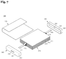
- FIG. 7 is an exploded perspective view illustrating a lithium polymer secondary battery according to another embodiment.
- a lithium polymer secondary battery 300 includes the electrode assembly 210 including the first electrode plates 211 and the second electrode plates 212 to which the electrode tabs 214 and 215 having different polarities to deliver a current to the outside are respectively attached, and the separators 213 disposed between the first and second electrode plates 211 and 212; the external member 120 wrapping or surrounding the electrode assembly 210; and first and second covers 330 and 340 each welded to a respective end of the external member 120.
- the electrode assembly 210 is formed by sequentially stacking the first electrode plates 211, the separators 213, and the second electrode plates 212.
- the electrode tabs 214 of the first electrode plates 211 and the electrode tabs 215 of the second electrode plates 212 extend in generally opposite directions from the electrode assembly. That is, the electrode tabs 214 of the first electrode plates 211 are attached to the electrode assembly 210 in a first direction, and the electrode tabs 215 of the second electrode plates 212 are attached to the electrode assembly 210 in a second direction opposite to the first direction.
- the electrode tabs 214 of the first electrode plates 211 is welded to the first electrode terminal 116, and the first electrode terminal 116 extends to the outside through the first cover 330.
- the electrode tabs 215 of the second electrode plates 212 are welded to the second electrode terminal 117, and the second electrode terminal 117 extends to the outside through the second cover 340.
- the electrode assembly 210 is a stack type electrode assembly like the embodiment of FIG. 6 , except that the extension direction of the first electrode terminal 116 is opposite to the extension direction of the second electrode terminal 117.
- the first electrode terminal 116 extends to the outside through the first cover 330
- the second electrode terminal 117 extends to the outside through the second cover 340.
- the electrode assembly 210 is the same as that of the embodiment of FIG. 6 , and a configuration of the external member 120 is substantially the same as the embodiment of FIG. 1 , descriptions thereof will be omitted.
- first and second covers 330 and 340 are substantially the same as those of the embodiment of FIG. 1 . That is, the first cover 330 includes a flat plate 331 and a side plate 332 attached to the flat plate 331 and having a terminal opening 333 at about the center of the flat plate 331, and the second cover 340 includes a flat plate 341 and a side plate 342 attached to the flat plate 341 with a terminal opening 343 at about the center of the flat plate 341.
- the positive electrode plates 211, the separators 213, and the negative electrode plates 212 are sequentially stacked to form the stack type electrode assembly 210. Then, the positive electrode tabs 214 are attached to the positive electrode plates 211 such that the positive electrode tabs 214 extend generally in the first direction with respect to the electrode assembly 210, and the negative electrode tabs 215 are attached to the negative electrode plate 212 such that the negative electrode tabs 215 extend generally in the second direction with respect to the electrode assembly 210.
- the upper end of the electrode assembly 210 corresponding to the first direction is coupled with the first cover 330.
- the first electrode terminal 116 passes through the terminal opening 333 of the first cover 330, and extends to the outside.
- the lower end of the electrode assembly 210 corresponding to the second direction is coupled with the second cover 340.
- the second electrode terminal 117 passes through the terminal opening 343 of the second cover 340, and extends to the outside. Contact portions of the first and second electrode terminals 116 and 117 passing through the first and second covers 330 and 340 are welded, and sealing material is applied to seal the contact portions.
- the external member 120 surrounds the side surface of the electrode assembly 210 and the side surfaces of the first and second covers 330 and 340, and both ends of the external member 120 overlap each other to be thermally compressed, that is, to be welded through heat welding, so that the sealing part 124 is formed.
- the upper end of the external member 120 is welded, e.g., thermally welded with the lower end of the first cover 330, and the lower end of the external member 120 is welded, e.g., thermally welded with the upper end of the second cover 340, like in the previous embodiments.
- a discrete gas chamber may be provided to inject electrolyte to the inside of the external member 120, and a structure of the gas chamber and a method of fabricating the gas chamber are substantially the same as those of the embodiment of FIG. 1 . Thus, descriptions thereof will be omitted.
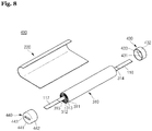
- FIG. 8 is an exploded perspective view illustrating a lithium polymer secondary battery according to another embodiment.
- a lithium polymer secondary battery 400 includes an electrode assembly 310 including a first electrode plate 311 and a second electrode plate 312 to which a plurality of electrode tabs 314 and 315 having different polarities to deliver a current to the outside are respectively attached, and a separator 313 disposed between the first and second electrode plates 311 and 312; an external member 220 surrounding the electrode assembly 310; and first and second covers 430 and 440 welded to both ends of the external member 220.
- the electrode assembly 310 is a cylindrical electrode assembly formed by winding the first electrode plate 311, the separator 313, and the second electrode plate 312 in a circular shape.
- the electrode tab 314 of the first electrode plate 311 and the electrode tab 315 of the second electrode plate 312 extend in opposite directions. That is, when the electrode tab 314 of the first electrode plate 311 is attached to the electrode assembly 310 in the first direction, the electrode tab 315 of the second electrode plate 312 may be attached to the electrode assembly 310 in the second direction opposite to the first direction.
- the electrode tab 314 of the first electrode plate 311 is welded to the first electrode terminal 116, and the first electrode terminal 116 extends to the outside through the first cover 430.
- the electrode tab 315 of the second electrode plate 312 is welded to the second electrode terminal 117, and the second electrode terminal 117 extends to the outside through the second cover 440.
- the electrode assembly 310 is a cylindrical electrode assembly, and the electrode tabs 314 and 315 are attached to the electrode assembly 310 in the different directions, so that the first and second electrode terminals 116 and 117 respectively extend through the first and second covers 430 and 440.
- the first electrode plate 311 of the electrode assembly 310 may be a positive electrode plate, and the second electrode plate 312 may be a negative electrode plate. However, the polarity of the first and second electrode plates may be reversed. Since configurations of the positive electrode plate, the negative electrode plate, and the separator 313 are substantially the same as those of the embodiment of FIG. 1 , descriptions thereof will be omitted.
- an external member 220 is substantially the same as that of the embodiment of FIG. 1 except that the external member 220 surrounds an exterior side surface of the cylindrical electrode assembly 310, a description thereof will be omitted.
- the first and second covers 430 and 440 are substantially the same as those of the embodiment of FIG. 1 in properties such as material.
- the first cover 430 includes a flat plate 431 and a side plate 432 attached to the flat plate 431, and the flat plate 431 is provided with a first terminal opening 433 through which the first electrode terminal 116 extends.
- the flat plate 431 is circular, and the side plate 432 extends from the edge of the flat plate 431.
- the positive electrode plate 311, the separator 313, and the negative electrode plate 312 are sequentially arrayed and wound in a cylindrical shape to form the cylindrical electrode assembly 310. Then, the positive electrode tab 314 is provided to the positive electrode plate 311 such that the positive electrode tab 314 extends generally in the first direction with respect to the electrode assembly 310, and the negative electrode tab 315 is attached to the negative electrode plate 312 such that the negative electrode tab 315 extends generally in the second direction with respect to the electrode assembly 310.
- the upper end of the electrode assembly 310 corresponding to the first direction is coupled with the first cover 430.
- the first electrode terminal 116 passes through the terminal opening 433 of the first cover 430, and extends to the outside.
- the lower end of the electrode assembly 310 corresponding to the second direction is coupled with the second cover 440.
- the second electrode terminal 117 passes through the terminal opening 443 of the second cover 440, and extends to the outside. Contact portions of the first and second electrode terminals 116 and 117 passing through the first and second covers 430 and 440 are welded, and sealing material is applied to seal the contact portions.
- the external member 220 wraps around or surrounds the side surface of the electrode assembly 310 and the side surfaces of the first and second covers 430 and 440, and two edges of the external member 420 overlap each other to allow two side surface of the external member 420 to be thermally compressed, that is, to be welded through heat welding, so that a sealing part is formed.
- the upper end of the external member 220 is welded, e.g., thermally welded with the lower end of the first cover 430, and the lower end of the external member 220 is welded, e.g., thermally welded with the upper end of the second cover 440, like in the previous embodiments.
- a discrete gas chamber may be provided to inject electrolyte to the inside of the external member 220, and a structure of the gas chamber and a method of fabricating the gas chamber are substantially the same as those of the embodiment of FIG. 1 . Thus, descriptions thereof will be omitted.
- a sealing part also called a terrace part in which a circuit board provided with a protective circuit is installed, or in which an electrode tab is disposed by opening a surface of a pouch type external member of a related art lithium polymer battery is not required.
- a sealing part also called a terrace part in which a circuit board provided with a protective circuit is installed, or in which an electrode tab is disposed by opening a surface of a pouch type external member of a related art lithium polymer battery is not required.
- the cap-shaped covers or the plate-shaped covers are welded to the upper and lower ends of the external case, and the electrode terminals of the electrode assembly extend through the covers.
- the space between the electrode terminals and the covers is sealed through welding or sealing liquid, so as to simplify a sealing process and improve sealing conditions.
Landscapes
- Chemical & Material Sciences (AREA)
- Chemical Kinetics & Catalysis (AREA)
- Electrochemistry (AREA)
- General Chemical & Material Sciences (AREA)
- Engineering & Computer Science (AREA)
- Manufacturing & Machinery (AREA)
- Connection Of Batteries Or Terminals (AREA)
- Sealing Battery Cases Or Jackets (AREA)
- Secondary Cells (AREA)
- Filling, Topping-Up Batteries (AREA)
Claims (14)
- Batterie secondaire comprenant :un ensemble d'électrodes (110, 210, 310) comprenant une première plaque d'électrode (111), une seconde plaque d'électrode (112) et un séparateur (113) entre la première plaque d'électrode et la seconde plaque d'électrode ;une première borne d'électrode (116) électriquement couplée à la première plaque d'électrode et une seconde borne d'électrode (117) électriquement couplée à la seconde plaque d'électrode ; etun premier couvercle (130, 230, 330, 430) et un second couvercle (140, 240, 340, 440) respectivement couplés aux parties d'extrémité de l'ensemble d'électrodes afin de recouvrir une première surface d'extrémité et une seconde surface d'extrémité, respectivement, de l'ensemble d'électrodes,dans laquelle la première borne d'électrode et la seconde borne d'électrode passent à travers une ouverture de borne (133, 143, 233, 234, 333, 343, 433, 443) correspondante dans au moins l'un des premier et second couvercles ;la batterie secondaire comprenant en outre :un organe externe (120) enroulé autour des surfaces latérales de l'ensemble d'électrodes et des surfaces latérales des premier et second couvercles, l'organe externe comprenant un film stratifié,dans laquelle deux bords de l'organe externe se chevauchent et sont soudés ensemble, et les première et seconde extrémités de l'organe externe sont soudées aux premier et second couvercles, respectivement, de sorte que l'ensemble d'électrode est scellé.
- Batterie secondaire selon la revendication 1, dans laquelle la première borne d'électrode fait saillie du premier couvercle et la seconde borne d'électrode fait saillie du second couvercle.
- Batterie secondaire selon la revendication 1, dans laquelle la première borne d'électrode et la seconde borne d'électrode font saillie du premier couvercle.
- Batterie secondaire selon l'une quelconque des revendications précédentes, dans laquelle l'organe externe comprend une chambre à gaz (170) dans laquelle est déchargé le gaz généré pendant la charge et la décharge de la batterie secondaire, et dans laquelle la chambre à gaz est configurée pour injecter un électrolyte dans la batterie secondaire.
- Batterie secondaire selon l'une quelconque des revendications précédentes, dans laquelle l'organe externe comprend un film stratifié ayant une forme de feuille sensiblement rectangulaire.
- Batterie secondaire selon la revendication 5, dans laquelle l'organe externe a une épaisseur comprise entre 170 µm et 300 µm.
- Batterie secondaire selon l'une quelconque des revendications précédentes, dans laquelle l'organe externe comprend une couche externe (122), une couche de protection (121) et une couche interne (123) empilées ensemble.
- Batterie secondaire selon l'une quelconque des revendications précédentes, dans laquelle l'un ou les deux parmi le premier couvercle et le second couvercle ont une forme de capuchon ayant une cavité définie par une plaque latérale et une plaque plate.
- Batterie secondaire selon la revendication 1, dans laquelle le premier couvercle a une ouverture de borne (133, 333, 433) à travers laquelle la première borne d'électrode fait saillie, et le second couvercle a une ouverture de borne (143, 343, 443) à travers laquelle la seconde borne d'électrode fait saillie.
- Batterie secondaire selon la revendication 9, dans laquelle la première borne d'électrode est soudée au premier couvercle au niveau de la première ouverture de borne et la seconde borne d'électrode est soudée au second couvercle au niveau de la seconde ouverture de borne.
- Batterie secondaire selon la revendication 1, dans laquelle le premier couvercle a une première ouverture de borne (233) et une seconde ouverture de borne (234) à travers laquelle la première borne d'électrode et la seconde borne d'électrode font respectivement saillie.
- Batterie secondaire selon la revendication 11, dans laquelle la première borne d'électrode et la seconde borne d'électrode sont soudées au premier couvercle au niveau de la première ouverture de borne et au niveau de la seconde ouverture de borne, respectivement.
- Batterie secondaire selon l'une quelconque des revendications précédentes, dans laquelle le premier couvercle et le second couvercle comprennent du polypropylène ou du polyéthylène.
- Batterie secondaire selon l'une quelconque des revendications précédentes, dans laquelle l'ensemble d'électrodes est un ensemble d'électrodes (210) de type à empilement dans lequel la première plaque d'électrode, le séparateur et la seconde plaque d'électrode sont empilés de manière séquentielle, ou dans laquelle l'ensemble d'électrodes est un ensemble d'électrodes (110) du type gâteau roulé dans lequel la première plaque d'électrode, le séparateur et la seconde plaque d'électrode sont enroulés ensemble et comprimés, ou dans laquelle l'ensemble d'électrodes est un ensemble d'électrodes cylindrique (310) dans lequel la première plaque d'électrode, le séparateur et la seconde plaque d'électrode sont enroulés selon une forme cylindrique.
Applications Claiming Priority (1)
| Application Number | Priority Date | Filing Date | Title |
|---|---|---|---|
| KR1020090110519A KR20110053835A (ko) | 2009-11-16 | 2009-11-16 | 리튬 폴리머 이차 전지 |
Publications (2)
| Publication Number | Publication Date |
|---|---|
| EP2333891A1 EP2333891A1 (fr) | 2011-06-15 |
| EP2333891B1 true EP2333891B1 (fr) | 2020-09-16 |
Family
ID=43598416
Family Applications (1)
| Application Number | Title | Priority Date | Filing Date |
|---|---|---|---|
| EP10191323.4A Active EP2333891B1 (fr) | 2009-11-16 | 2010-11-16 | Batterie secondaire |
Country Status (5)
| Country | Link |
|---|---|
| US (1) | US9099696B2 (fr) |
| EP (1) | EP2333891B1 (fr) |
| JP (1) | JP5395749B2 (fr) |
| KR (1) | KR20110053835A (fr) |
| CN (1) | CN102064338B (fr) |
Families Citing this family (52)
| Publication number | Priority date | Publication date | Assignee | Title |
|---|---|---|---|---|
| KR101230994B1 (ko) * | 2010-12-03 | 2013-02-07 | 기아자동차주식회사 | 중대형 배터리 |
| JP6160350B2 (ja) * | 2013-08-06 | 2017-07-12 | 株式会社豊田自動織機 | 蓄電装置 |
| US9991498B2 (en) | 2013-09-09 | 2018-06-05 | Samsung Electronics Co., Ltd. | Electrode assembly and secondary battery including the same |
| KR102489488B1 (ko) | 2014-05-16 | 2023-01-18 | 가부시키가이샤 한도오따이 에네루기 켄큐쇼 | 이차 전지를 가지는 전자 기기 |
| KR20160148316A (ko) | 2015-06-16 | 2016-12-26 | 삼성에스디아이 주식회사 | 이차 전지 |
| KR102513784B1 (ko) * | 2015-10-07 | 2023-03-23 | 에스케이온 주식회사 | 리튬 이차 전지 |
| KR102217444B1 (ko) * | 2017-04-06 | 2021-02-22 | 주식회사 엘지화학 | 전극조립체 및 그 전극조립체의 제조 방법 |
| KR102475343B1 (ko) | 2018-03-02 | 2022-12-08 | 주식회사 엘지에너지솔루션 | 이차 전지 및 그의 제조 방법 |
| CN110364643B (zh) * | 2018-03-26 | 2021-05-18 | 宁德时代新能源科技股份有限公司 | 二次电池以及二次电池的制造方法 |
| US11450909B2 (en) * | 2018-09-12 | 2022-09-20 | Cardiac Pacemakers, Inc. | Open tube battery housing |
| DE102019202408A1 (de) | 2018-12-17 | 2020-06-18 | Robert Bosch Gmbh | Verfahren zur Herstellung einer Batteriezelle sowie Batteriezelle und Verwendung der Batteriezelle |
| CN111509286B (zh) * | 2019-01-31 | 2021-10-22 | 东莞新能安科技有限公司 | 电芯及电池 |
| KR102809759B1 (ko) * | 2019-10-14 | 2025-05-16 | 주식회사 엘지에너지솔루션 | 배터리 셀, 이러한 배터리 셀을 포함하는 배터리 모듈 및 이러한 배터리 모듈을 포함하는 배터리 팩 |
| WO2021157731A1 (fr) * | 2020-02-07 | 2021-08-12 | 大日本印刷株式会社 | Dispositif de stockage d'énergie et procédé de fabrication de dispositif de stockage d'énergie |
| KR102924942B1 (ko) | 2020-09-29 | 2026-02-10 | 에스케이온 주식회사 | 배터리 셀 및 이를 구비하는 배터리 모듈과 배터리 팩 |
| JP7302614B2 (ja) * | 2021-02-12 | 2023-07-04 | トヨタ自動車株式会社 | 二次電池 |
| JP7537414B2 (ja) | 2021-12-06 | 2024-08-21 | トヨタ自動車株式会社 | 二次電池 |
| KR20230085070A (ko) | 2021-12-06 | 2023-06-13 | 도요타 지도샤(주) | 이차전지 |
| KR20230089378A (ko) * | 2021-12-13 | 2023-06-20 | 에스케이온 주식회사 | 이차 전지 |
| KR20240125557A (ko) * | 2021-12-17 | 2024-08-19 | 다이니폰 인사츠 가부시키가이샤 | 축전 디바이스, 커버체, 축전 디바이스의 제조 방법 |
| EP4553969A3 (fr) * | 2022-02-26 | 2025-11-12 | Dai Nippon Printing Co., Ltd. | Corps de couvercle, unité de corps de couvercle, dispositif de stockage d'énergie électrique, procédé de fabrication d'unité de corps de couvercle et procédé de fabrication de dispositif de stockage d'énergie électrique |
| JP7679578B2 (ja) | 2022-04-28 | 2025-05-20 | トヨタ自動車株式会社 | 電池、電池モジュールおよび電池の製造方法 |
| JP7276573B1 (ja) * | 2022-07-08 | 2023-05-18 | 大日本印刷株式会社 | 蓄電デバイス、電動自動車、蓄電デバイス用包装容器及びその製造方法 |
| JP7276572B1 (ja) | 2022-07-08 | 2023-05-18 | 大日本印刷株式会社 | 蓄電デバイス及び電動自動車 |
| JP7524928B2 (ja) | 2022-07-15 | 2024-07-30 | トヨタ自動車株式会社 | 電池および電池の製造方法 |
| US20240030523A1 (en) | 2022-07-25 | 2024-01-25 | Aesc Japan Ltd. | Battery cell |
| JP2024015598A (ja) * | 2022-07-25 | 2024-02-06 | 株式会社Aescジャパン | 電池セル |
| US20240039092A1 (en) | 2022-07-28 | 2024-02-01 | Aesc Japan Ltd. | Battery cell |
| JP2024017790A (ja) * | 2022-07-28 | 2024-02-08 | 株式会社Aescジャパン | 電池セル |
| JP7833989B2 (ja) * | 2022-08-12 | 2026-03-23 | 株式会社Aescジャパン | 電池セル |
| US20240039091A1 (en) | 2022-07-28 | 2024-02-01 | Aesc Japan Ltd. | Battery cell |
| JP7743820B2 (ja) | 2022-07-28 | 2025-09-25 | トヨタ自動車株式会社 | 電池 |
| JP7661944B2 (ja) | 2022-08-15 | 2025-04-15 | トヨタ自動車株式会社 | 電池 |
| JP7567879B2 (ja) | 2022-09-01 | 2024-10-16 | トヨタ自動車株式会社 | 電池、電池モジュールおよび電池の製造方法 |
| JP7650419B2 (ja) | 2022-09-12 | 2025-03-25 | トヨタ自動車株式会社 | タブフィルムカット方法 |
| WO2024063103A1 (fr) * | 2022-09-22 | 2024-03-28 | 株式会社村田製作所 | Batterie secondaire |
| CN120077509A (zh) * | 2022-10-12 | 2025-05-30 | 大日本印刷株式会社 | 蓄电器件 |
| JP7771928B2 (ja) | 2022-11-10 | 2025-11-18 | トヨタ自動車株式会社 | ラミネート型電池、電池モジュール、およびラミネート型電池の製造方法 |
| JP7712558B2 (ja) | 2022-11-29 | 2025-07-24 | トヨタ自動車株式会社 | ラミネート型電池、及びラミネート型電池の製造方法 |
| DE102023201904A1 (de) * | 2023-03-02 | 2024-09-05 | Volkswagen Aktiengesellschaft | Verfahren zur Herstellung einer Batteriezelle, eine Batteriezellenkomponente sowie eine Batteriezelle |
| KR20250160887A (ko) * | 2023-03-06 | 2025-11-14 | 다이니폰 인사츠 가부시키가이샤 | 축전 디바이스의 제조 방법, 및 축전 디바이스 |
| KR20250168185A (ko) * | 2023-03-29 | 2025-12-02 | 다이니폰 인사츠 가부시키가이샤 | 축전 디바이스 및 그 제조 방법 |
| JP7726412B2 (ja) * | 2023-03-29 | 2025-08-20 | 大日本印刷株式会社 | 蓄電デバイス及び蓄電デバイス用の保護部材 |
| JP2024157625A (ja) | 2023-04-26 | 2024-11-08 | 株式会社Aescジャパン | 電池セル |
| WO2024248570A1 (fr) * | 2023-06-01 | 2024-12-05 | 주식회사 엘지에너지솔루션 | Batterie secondaire |
| JP2025008745A (ja) * | 2023-07-06 | 2025-01-20 | トヨタ自動車株式会社 | 蓄電セル |
| JP7750453B2 (ja) * | 2023-10-02 | 2025-10-07 | 大日本印刷株式会社 | 蓄電デバイス、蓄電デバイス製造キット及び蓄電デバイスの製造方法 |
| KR20250082269A (ko) * | 2023-11-30 | 2025-06-09 | 주식회사 엘지에너지솔루션 | 이차전지 |
| WO2025127882A1 (fr) * | 2023-12-15 | 2025-06-19 | 주식회사 엘지에너지솔루션 | Procédé de fabrication de batterie secondaire |
| JP7790640B1 (ja) * | 2024-03-06 | 2025-12-23 | 大日本印刷株式会社 | 蓋体、蓄電デバイス、蓄電デバイスの製造方法 |
| KR20260020788A (ko) * | 2024-08-05 | 2026-02-12 | 주식회사 엘지에너지솔루션 | 이차 전지 및 이를 포함하는 배터리 팩 |
| WO2026071634A1 (fr) * | 2024-09-27 | 2026-04-02 | 주식회사 엘지에너지솔루션 | Batterie secondaire et procédé de fabrication de batterie secondaire |
Citations (1)
| Publication number | Priority date | Publication date | Assignee | Title |
|---|---|---|---|---|
| EP2337106A2 (fr) * | 2009-10-13 | 2011-06-22 | Samsung SDI Co., Ltd. | Batterie rechargeable |
Family Cites Families (18)
| Publication number | Priority date | Publication date | Assignee | Title |
|---|---|---|---|---|
| FR2770032B1 (fr) * | 1997-10-16 | 1999-12-17 | Alsthom Cge Alcatel | Accumulateur etanche a enveloppe multicouche |
| US6083640A (en) * | 1998-09-22 | 2000-07-04 | Samsung Display Device Co., Ltd. | Secondary battery with electrode assembly fixing device |
| KR100303828B1 (ko) | 1998-09-22 | 2001-10-19 | 김순택 | 이차전지 |
| JP3900507B2 (ja) | 1998-11-30 | 2007-04-04 | ソニー株式会社 | 非水電解質電池 |
| KR20040005022A (ko) | 2002-07-08 | 2004-01-16 | 삼성에스디아이 주식회사 | 이차전지용 케이스와 이를 성형하는 다이 |
| JP2004303535A (ja) | 2003-03-31 | 2004-10-28 | Mitsubishi Materials Corp | 平板状単電池の組電池 |
| JP4857742B2 (ja) | 2005-12-02 | 2012-01-18 | ソニー株式会社 | 電池パック |
| JP2005142416A (ja) | 2003-11-07 | 2005-06-02 | Nisshinbo Ind Inc | 密閉型蓄電装置及びその製造方法 |
| JP4424053B2 (ja) | 2004-04-28 | 2010-03-03 | トヨタ自動車株式会社 | ラミネート型二次電池、およびその組電池 |
| JP4765439B2 (ja) * | 2004-07-23 | 2011-09-07 | ソニー株式会社 | 電池パック |
| US20060099501A1 (en) * | 2004-10-28 | 2006-05-11 | Kim Ka Y | Secondary battery |
| US7682735B2 (en) * | 2005-03-28 | 2010-03-23 | Samsung Sdi Co., Ltd. | Pouch type lithium secondary battery and method of fabricating the same |
| KR100824897B1 (ko) | 2005-12-29 | 2008-04-23 | 삼성에스디아이 주식회사 | 파우치형 전지 및 그 형성 방법 |
| JP4599314B2 (ja) * | 2006-02-22 | 2010-12-15 | 株式会社東芝 | 非水電解質電池、電池パック及び自動車 |
| JP4458145B2 (ja) | 2007-10-15 | 2010-04-28 | ソニー株式会社 | 電池パックおよびその製造方法 |
| KR100928120B1 (ko) * | 2007-11-07 | 2009-11-24 | 삼성에스디아이 주식회사 | 이차 전지 |
| WO2009079029A1 (fr) * | 2007-12-19 | 2009-06-25 | American Lithium Energy Corporation | Enceinte de batterie |
| KR101042766B1 (ko) * | 2009-02-05 | 2011-06-20 | 삼성에스디아이 주식회사 | 배터리 팩 및 그 제조 방법 |
-
2009
- 2009-11-16 KR KR1020090110519A patent/KR20110053835A/ko not_active Ceased
-
2010
- 2010-06-04 JP JP2010128961A patent/JP5395749B2/ja active Active
- 2010-10-29 US US12/916,449 patent/US9099696B2/en active Active
- 2010-11-16 EP EP10191323.4A patent/EP2333891B1/fr active Active
- 2010-11-16 CN CN201010549700.8A patent/CN102064338B/zh active Active
Patent Citations (1)
| Publication number | Priority date | Publication date | Assignee | Title |
|---|---|---|---|---|
| EP2337106A2 (fr) * | 2009-10-13 | 2011-06-22 | Samsung SDI Co., Ltd. | Batterie rechargeable |
Also Published As
| Publication number | Publication date |
|---|---|
| JP2011108623A (ja) | 2011-06-02 |
| EP2333891A1 (fr) | 2011-06-15 |
| US20110117404A1 (en) | 2011-05-19 |
| JP5395749B2 (ja) | 2014-01-22 |
| CN102064338A (zh) | 2011-05-18 |
| CN102064338B (zh) | 2014-03-12 |
| US9099696B2 (en) | 2015-08-04 |
| KR20110053835A (ko) | 2011-05-24 |
Similar Documents
| Publication | Publication Date | Title |
|---|---|---|
| EP2333891B1 (fr) | Batterie secondaire | |
| US8895180B2 (en) | Lithium polymer secondary battery with external wrapping member | |
| US7858228B2 (en) | Rechargeable battery | |
| CN102035013B (zh) | 二次电池和制造二次电池的方法 | |
| US8628876B2 (en) | Electrode assembly and lithium secondary battery with same | |
| JP5122072B2 (ja) | リチウム二次電池 | |
| KR101175057B1 (ko) | 리튬 폴리머 이차 전지 | |
| US8815434B2 (en) | Electrode assembly for secondary battery with wound and folded separator portions and secondary battery having the same | |
| US20120052341A1 (en) | Rechargeable battery | |
| EP2610945B1 (fr) | Cellule empilée | |
| US20090098418A1 (en) | Battery pack and method of fabricating the same | |
| US8546005B2 (en) | Cap assembly and secondary battery having the same | |
| KR101696964B1 (ko) | 코팅층이 형성된 원통형 이차전지 | |
| US9023500B2 (en) | Cylindrical secondary battery | |
| KR100973314B1 (ko) | 보호회로 조립체 및 이를 구비하는 배터리 팩 | |
| KR101308296B1 (ko) | 리튬 이차 전지 | |
| US20050042507A1 (en) | Secondary battery and method with electrode tap positioned at short side portion of secondary battery can | |
| US20110151287A1 (en) | Battery pack | |
| KR101264432B1 (ko) | 단차부가 형성된 외부케이스를 구비한 전지 팩 | |
| KR20080024859A (ko) | 전지 팩 |
Legal Events
| Date | Code | Title | Description |
|---|---|---|---|
| PUAI | Public reference made under article 153(3) epc to a published international application that has entered the european phase |
Free format text: ORIGINAL CODE: 0009012 |
|
| 17P | Request for examination filed |
Effective date: 20101116 |
|
| AK | Designated contracting states |
Kind code of ref document: A1 Designated state(s): AL AT BE BG CH CY CZ DE DK EE ES FI FR GB GR HR HU IE IS IT LI LT LU LV MC MK MT NL NO PL PT RO RS SE SI SK SM TR |
|
| AX | Request for extension of the european patent |
Extension state: BA ME |
|
| 17Q | First examination report despatched |
Effective date: 20120730 |
|
| STAA | Information on the status of an ep patent application or granted ep patent |
Free format text: STATUS: EXAMINATION IS IN PROGRESS |
|
| GRAP | Despatch of communication of intention to grant a patent |
Free format text: ORIGINAL CODE: EPIDOSNIGR1 |
|
| STAA | Information on the status of an ep patent application or granted ep patent |
Free format text: STATUS: GRANT OF PATENT IS INTENDED |
|
| INTG | Intention to grant announced |
Effective date: 20200610 |
|
| GRAS | Grant fee paid |
Free format text: ORIGINAL CODE: EPIDOSNIGR3 |
|
| GRAA | (expected) grant |
Free format text: ORIGINAL CODE: 0009210 |
|
| STAA | Information on the status of an ep patent application or granted ep patent |
Free format text: STATUS: THE PATENT HAS BEEN GRANTED |
|
| AK | Designated contracting states |
Kind code of ref document: B1 Designated state(s): AL AT BE BG CH CY CZ DE DK EE ES FI FR GB GR HR HU IE IS IT LI LT LU LV MC MK MT NL NO PL PT RO RS SE SI SK SM TR |
|
| REG | Reference to a national code |
Ref country code: GB Ref legal event code: FG4D |
|
| REG | Reference to a national code |
Ref country code: CH Ref legal event code: EP |
|
| REG | Reference to a national code |
Ref country code: DE Ref legal event code: R096 Ref document number: 602010065453 Country of ref document: DE |
|
| REG | Reference to a national code |
Ref country code: IE Ref legal event code: FG4D |
|
| REG | Reference to a national code |
Ref country code: AT Ref legal event code: REF Ref document number: 1314971 Country of ref document: AT Kind code of ref document: T Effective date: 20201015 |
|
| PG25 | Lapsed in a contracting state [announced via postgrant information from national office to epo] |
Ref country code: SE Free format text: LAPSE BECAUSE OF FAILURE TO SUBMIT A TRANSLATION OF THE DESCRIPTION OR TO PAY THE FEE WITHIN THE PRESCRIBED TIME-LIMIT Effective date: 20200916 Ref country code: HR Free format text: LAPSE BECAUSE OF FAILURE TO SUBMIT A TRANSLATION OF THE DESCRIPTION OR TO PAY THE FEE WITHIN THE PRESCRIBED TIME-LIMIT Effective date: 20200916 Ref country code: GR Free format text: LAPSE BECAUSE OF FAILURE TO SUBMIT A TRANSLATION OF THE DESCRIPTION OR TO PAY THE FEE WITHIN THE PRESCRIBED TIME-LIMIT Effective date: 20201217 Ref country code: NO Free format text: LAPSE BECAUSE OF FAILURE TO SUBMIT A TRANSLATION OF THE DESCRIPTION OR TO PAY THE FEE WITHIN THE PRESCRIBED TIME-LIMIT Effective date: 20201216 Ref country code: BG Free format text: LAPSE BECAUSE OF FAILURE TO SUBMIT A TRANSLATION OF THE DESCRIPTION OR TO PAY THE FEE WITHIN THE PRESCRIBED TIME-LIMIT Effective date: 20201216 Ref country code: FI Free format text: LAPSE BECAUSE OF FAILURE TO SUBMIT A TRANSLATION OF THE DESCRIPTION OR TO PAY THE FEE WITHIN THE PRESCRIBED TIME-LIMIT Effective date: 20200916 |
|
| REG | Reference to a national code |
Ref country code: AT Ref legal event code: MK05 Ref document number: 1314971 Country of ref document: AT Kind code of ref document: T Effective date: 20200916 |
|
| REG | Reference to a national code |
Ref country code: NL Ref legal event code: MP Effective date: 20200916 |
|
| PG25 | Lapsed in a contracting state [announced via postgrant information from national office to epo] |
Ref country code: LV Free format text: LAPSE BECAUSE OF FAILURE TO SUBMIT A TRANSLATION OF THE DESCRIPTION OR TO PAY THE FEE WITHIN THE PRESCRIBED TIME-LIMIT Effective date: 20200916 Ref country code: RS Free format text: LAPSE BECAUSE OF FAILURE TO SUBMIT A TRANSLATION OF THE DESCRIPTION OR TO PAY THE FEE WITHIN THE PRESCRIBED TIME-LIMIT Effective date: 20200916 |
|
| REG | Reference to a national code |
Ref country code: LT Ref legal event code: MG4D |
|
| PG25 | Lapsed in a contracting state [announced via postgrant information from national office to epo] |
Ref country code: PT Free format text: LAPSE BECAUSE OF FAILURE TO SUBMIT A TRANSLATION OF THE DESCRIPTION OR TO PAY THE FEE WITHIN THE PRESCRIBED TIME-LIMIT Effective date: 20210118 Ref country code: LT Free format text: LAPSE BECAUSE OF FAILURE TO SUBMIT A TRANSLATION OF THE DESCRIPTION OR TO PAY THE FEE WITHIN THE PRESCRIBED TIME-LIMIT Effective date: 20200916 Ref country code: NL Free format text: LAPSE BECAUSE OF FAILURE TO SUBMIT A TRANSLATION OF THE DESCRIPTION OR TO PAY THE FEE WITHIN THE PRESCRIBED TIME-LIMIT Effective date: 20200916 Ref country code: SM Free format text: LAPSE BECAUSE OF FAILURE TO SUBMIT A TRANSLATION OF THE DESCRIPTION OR TO PAY THE FEE WITHIN THE PRESCRIBED TIME-LIMIT Effective date: 20200916 Ref country code: RO Free format text: LAPSE BECAUSE OF FAILURE TO SUBMIT A TRANSLATION OF THE DESCRIPTION OR TO PAY THE FEE WITHIN THE PRESCRIBED TIME-LIMIT Effective date: 20200916 Ref country code: CZ Free format text: LAPSE BECAUSE OF FAILURE TO SUBMIT A TRANSLATION OF THE DESCRIPTION OR TO PAY THE FEE WITHIN THE PRESCRIBED TIME-LIMIT Effective date: 20200916 Ref country code: EE Free format text: LAPSE BECAUSE OF FAILURE TO SUBMIT A TRANSLATION OF THE DESCRIPTION OR TO PAY THE FEE WITHIN THE PRESCRIBED TIME-LIMIT Effective date: 20200916 |
|
| PG25 | Lapsed in a contracting state [announced via postgrant information from national office to epo] |
Ref country code: PL Free format text: LAPSE BECAUSE OF FAILURE TO SUBMIT A TRANSLATION OF THE DESCRIPTION OR TO PAY THE FEE WITHIN THE PRESCRIBED TIME-LIMIT Effective date: 20200916 Ref country code: IS Free format text: LAPSE BECAUSE OF FAILURE TO SUBMIT A TRANSLATION OF THE DESCRIPTION OR TO PAY THE FEE WITHIN THE PRESCRIBED TIME-LIMIT Effective date: 20210116 Ref country code: ES Free format text: LAPSE BECAUSE OF FAILURE TO SUBMIT A TRANSLATION OF THE DESCRIPTION OR TO PAY THE FEE WITHIN THE PRESCRIBED TIME-LIMIT Effective date: 20200916 Ref country code: AT Free format text: LAPSE BECAUSE OF FAILURE TO SUBMIT A TRANSLATION OF THE DESCRIPTION OR TO PAY THE FEE WITHIN THE PRESCRIBED TIME-LIMIT Effective date: 20200916 Ref country code: AL Free format text: LAPSE BECAUSE OF FAILURE TO SUBMIT A TRANSLATION OF THE DESCRIPTION OR TO PAY THE FEE WITHIN THE PRESCRIBED TIME-LIMIT Effective date: 20200916 |
|
| REG | Reference to a national code |
Ref country code: DE Ref legal event code: R097 Ref document number: 602010065453 Country of ref document: DE |
|
| PG25 | Lapsed in a contracting state [announced via postgrant information from national office to epo] |
Ref country code: MC Free format text: LAPSE BECAUSE OF FAILURE TO SUBMIT A TRANSLATION OF THE DESCRIPTION OR TO PAY THE FEE WITHIN THE PRESCRIBED TIME-LIMIT Effective date: 20200916 Ref country code: SK Free format text: LAPSE BECAUSE OF FAILURE TO SUBMIT A TRANSLATION OF THE DESCRIPTION OR TO PAY THE FEE WITHIN THE PRESCRIBED TIME-LIMIT Effective date: 20200916 |
|
| REG | Reference to a national code |
Ref country code: CH Ref legal event code: PL |
|
| PLBE | No opposition filed within time limit |
Free format text: ORIGINAL CODE: 0009261 |
|
| STAA | Information on the status of an ep patent application or granted ep patent |
Free format text: STATUS: NO OPPOSITION FILED WITHIN TIME LIMIT |
|
| PG25 | Lapsed in a contracting state [announced via postgrant information from national office to epo] |
Ref country code: LU Free format text: LAPSE BECAUSE OF NON-PAYMENT OF DUE FEES Effective date: 20201116 |
|
| REG | Reference to a national code |
Ref country code: BE Ref legal event code: MM Effective date: 20201130 |
|
| 26N | No opposition filed |
Effective date: 20210617 |
|
| PG25 | Lapsed in a contracting state [announced via postgrant information from national office to epo] |
Ref country code: CH Free format text: LAPSE BECAUSE OF NON-PAYMENT OF DUE FEES Effective date: 20201130 Ref country code: DK Free format text: LAPSE BECAUSE OF FAILURE TO SUBMIT A TRANSLATION OF THE DESCRIPTION OR TO PAY THE FEE WITHIN THE PRESCRIBED TIME-LIMIT Effective date: 20200916 Ref country code: SI Free format text: LAPSE BECAUSE OF FAILURE TO SUBMIT A TRANSLATION OF THE DESCRIPTION OR TO PAY THE FEE WITHIN THE PRESCRIBED TIME-LIMIT Effective date: 20200916 Ref country code: LI Free format text: LAPSE BECAUSE OF NON-PAYMENT OF DUE FEES Effective date: 20201130 |
|
| PG25 | Lapsed in a contracting state [announced via postgrant information from national office to epo] |
Ref country code: IT Free format text: LAPSE BECAUSE OF FAILURE TO SUBMIT A TRANSLATION OF THE DESCRIPTION OR TO PAY THE FEE WITHIN THE PRESCRIBED TIME-LIMIT Effective date: 20200916 Ref country code: IE Free format text: LAPSE BECAUSE OF NON-PAYMENT OF DUE FEES Effective date: 20201116 |
|
| PG25 | Lapsed in a contracting state [announced via postgrant information from national office to epo] |
Ref country code: TR Free format text: LAPSE BECAUSE OF FAILURE TO SUBMIT A TRANSLATION OF THE DESCRIPTION OR TO PAY THE FEE WITHIN THE PRESCRIBED TIME-LIMIT Effective date: 20200916 Ref country code: MT Free format text: LAPSE BECAUSE OF FAILURE TO SUBMIT A TRANSLATION OF THE DESCRIPTION OR TO PAY THE FEE WITHIN THE PRESCRIBED TIME-LIMIT Effective date: 20200916 Ref country code: CY Free format text: LAPSE BECAUSE OF FAILURE TO SUBMIT A TRANSLATION OF THE DESCRIPTION OR TO PAY THE FEE WITHIN THE PRESCRIBED TIME-LIMIT Effective date: 20200916 |
|
| PG25 | Lapsed in a contracting state [announced via postgrant information from national office to epo] |
Ref country code: MK Free format text: LAPSE BECAUSE OF FAILURE TO SUBMIT A TRANSLATION OF THE DESCRIPTION OR TO PAY THE FEE WITHIN THE PRESCRIBED TIME-LIMIT Effective date: 20200916 |
|
| PG25 | Lapsed in a contracting state [announced via postgrant information from national office to epo] |
Ref country code: BE Free format text: LAPSE BECAUSE OF NON-PAYMENT OF DUE FEES Effective date: 20201130 |
|
| P01 | Opt-out of the competence of the unified patent court (upc) registered |
Effective date: 20230528 |
|
| PGFP | Annual fee paid to national office [announced via postgrant information from national office to epo] |
Ref country code: DE Payment date: 20251104 Year of fee payment: 16 |
|
| PGFP | Annual fee paid to national office [announced via postgrant information from national office to epo] |
Ref country code: GB Payment date: 20251030 Year of fee payment: 16 |
|
| PGFP | Annual fee paid to national office [announced via postgrant information from national office to epo] |
Ref country code: FR Payment date: 20251117 Year of fee payment: 16 |