EP2334399B1 - Verfahren zum herstellen einer filterendscheibe und eines fluidfilters, filterendscheibe - Google Patents
Verfahren zum herstellen einer filterendscheibe und eines fluidfilters, filterendscheibe Download PDFInfo
- Publication number
- EP2334399B1 EP2334399B1 EP09741257.1A EP09741257A EP2334399B1 EP 2334399 B1 EP2334399 B1 EP 2334399B1 EP 09741257 A EP09741257 A EP 09741257A EP 2334399 B1 EP2334399 B1 EP 2334399B1
- Authority
- EP
- European Patent Office
- Prior art keywords
- plastic mold
- mold material
- filter
- plastic
- filter end
- Prior art date
- Legal status (The legal status is an assumption and is not a legal conclusion. Google has not performed a legal analysis and makes no representation as to the accuracy of the status listed.)
- Not-in-force
Links
- 238000000034 method Methods 0.000 title claims description 61
- 239000012530 fluid Substances 0.000 title claims description 21
- 238000004519 manufacturing process Methods 0.000 title claims description 19
- 239000000463 material Substances 0.000 claims description 121
- 239000004033 plastic Substances 0.000 claims description 62
- 238000002347 injection Methods 0.000 claims description 34
- 239000007924 injection Substances 0.000 claims description 34
- 230000005855 radiation Effects 0.000 claims description 29
- XLYOFNOQVPJJNP-UHFFFAOYSA-N water Substances O XLYOFNOQVPJJNP-UHFFFAOYSA-N 0.000 claims description 22
- 238000010521 absorption reaction Methods 0.000 claims description 17
- 239000007787 solid Substances 0.000 claims description 8
- 238000002844 melting Methods 0.000 claims description 7
- 230000008018 melting Effects 0.000 claims description 7
- 230000005540 biological transmission Effects 0.000 claims description 4
- 238000010137 moulding (plastic) Methods 0.000 description 99
- 239000012778 molding material Substances 0.000 description 98
- 230000008569 process Effects 0.000 description 25
- 239000011162 core material Substances 0.000 description 18
- 238000007789 sealing Methods 0.000 description 15
- 239000010410 layer Substances 0.000 description 11
- 239000004952 Polyamide Substances 0.000 description 10
- 229920002647 polyamide Polymers 0.000 description 10
- 238000012545 processing Methods 0.000 description 8
- 238000001746 injection moulding Methods 0.000 description 7
- -1 for example Substances 0.000 description 6
- 238000003860 storage Methods 0.000 description 6
- 239000004743 Polypropylene Substances 0.000 description 5
- 239000000203 mixture Substances 0.000 description 5
- 229920001155 polypropylene Polymers 0.000 description 5
- 239000012815 thermoplastic material Substances 0.000 description 5
- 239000007788 liquid Substances 0.000 description 4
- 239000012768 molten material Substances 0.000 description 4
- 238000002834 transmittance Methods 0.000 description 4
- 238000003466 welding Methods 0.000 description 4
- 238000001816 cooling Methods 0.000 description 3
- 239000000945 filler Substances 0.000 description 3
- 239000000446 fuel Substances 0.000 description 3
- 238000010438 heat treatment Methods 0.000 description 3
- 239000000155 melt Substances 0.000 description 3
- 230000008859 change Effects 0.000 description 2
- 238000006243 chemical reaction Methods 0.000 description 2
- 238000009826 distribution Methods 0.000 description 2
- 238000005516 engineering process Methods 0.000 description 2
- 239000004744 fabric Substances 0.000 description 2
- 230000002349 favourable effect Effects 0.000 description 2
- 238000001914 filtration Methods 0.000 description 2
- 239000006260 foam Substances 0.000 description 2
- 239000002245 particle Substances 0.000 description 2
- 230000035515 penetration Effects 0.000 description 2
- 230000001681 protective effect Effects 0.000 description 2
- 238000007711 solidification Methods 0.000 description 2
- 238000007792 addition Methods 0.000 description 1
- 239000000654 additive Substances 0.000 description 1
- 239000000853 adhesive Substances 0.000 description 1
- 230000001070 adhesive effect Effects 0.000 description 1
- 230000008901 benefit Effects 0.000 description 1
- 239000006229 carbon black Substances 0.000 description 1
- 238000004040 coloring Methods 0.000 description 1
- 150000001875 compounds Chemical class 0.000 description 1
- 230000007423 decrease Effects 0.000 description 1
- 230000001419 dependent effect Effects 0.000 description 1
- 238000013461 design Methods 0.000 description 1
- 238000011161 development Methods 0.000 description 1
- 238000010586 diagram Methods 0.000 description 1
- 238000006073 displacement reaction Methods 0.000 description 1
- 239000000975 dye Substances 0.000 description 1
- 238000000465 moulding Methods 0.000 description 1
- 239000002985 plastic film Substances 0.000 description 1
- 229920006255 plastic film Polymers 0.000 description 1
- 239000011241 protective layer Substances 0.000 description 1
- 230000002787 reinforcement Effects 0.000 description 1
- 238000007493 shaping process Methods 0.000 description 1
- 230000008023 solidification Effects 0.000 description 1
- 239000004071 soot Substances 0.000 description 1
- 229920001169 thermoplastic Polymers 0.000 description 1
- 238000009757 thermoplastic moulding Methods 0.000 description 1
- 239000004416 thermosoftening plastic Substances 0.000 description 1
- 238000012546 transfer Methods 0.000 description 1
- 230000007704 transition Effects 0.000 description 1
Images


Classifications
-
- B—PERFORMING OPERATIONS; TRANSPORTING
- B01—PHYSICAL OR CHEMICAL PROCESSES OR APPARATUS IN GENERAL
- B01D—SEPARATION
- B01D29/00—Filters with filtering elements stationary during filtration, e.g. pressure or suction filters, not covered by groups B01D24/00 - B01D27/00; Filtering elements therefor
- B01D29/11—Filters with filtering elements stationary during filtration, e.g. pressure or suction filters, not covered by groups B01D24/00 - B01D27/00; Filtering elements therefor with bag, cage, hose, tube, sleeve or like filtering elements
- B01D29/111—Making filtering elements
-
- B—PERFORMING OPERATIONS; TRANSPORTING
- B01—PHYSICAL OR CHEMICAL PROCESSES OR APPARATUS IN GENERAL
- B01D—SEPARATION
- B01D29/00—Filters with filtering elements stationary during filtration, e.g. pressure or suction filters, not covered by groups B01D24/00 - B01D27/00; Filtering elements therefor
- B01D29/11—Filters with filtering elements stationary during filtration, e.g. pressure or suction filters, not covered by groups B01D24/00 - B01D27/00; Filtering elements therefor with bag, cage, hose, tube, sleeve or like filtering elements
- B01D29/13—Supported filter elements
- B01D29/15—Supported filter elements arranged for inward flow filtration
- B01D29/21—Supported filter elements arranged for inward flow filtration with corrugated, folded or wound sheets
-
- B—PERFORMING OPERATIONS; TRANSPORTING
- B01—PHYSICAL OR CHEMICAL PROCESSES OR APPARATUS IN GENERAL
- B01D—SEPARATION
- B01D46/00—Filters or filtering processes specially modified for separating dispersed particles from gases or vapours
- B01D46/0002—Casings; Housings; Frame constructions
-
- B—PERFORMING OPERATIONS; TRANSPORTING
- B29—WORKING OF PLASTICS; WORKING OF SUBSTANCES IN A PLASTIC STATE IN GENERAL
- B29C—SHAPING OR JOINING OF PLASTICS; SHAPING OF MATERIAL IN A PLASTIC STATE, NOT OTHERWISE PROVIDED FOR; AFTER-TREATMENT OF THE SHAPED PRODUCTS, e.g. REPAIRING
- B29C45/00—Injection moulding, i.e. forcing the required volume of moulding material through a nozzle into a closed mould; Apparatus therefor
- B29C45/16—Making multilayered or multicoloured articles
- B29C45/1642—Making multilayered or multicoloured articles having a "sandwich" structure
-
- B—PERFORMING OPERATIONS; TRANSPORTING
- B01—PHYSICAL OR CHEMICAL PROCESSES OR APPARATUS IN GENERAL
- B01D—SEPARATION
- B01D2201/00—Details relating to filtering apparatus
- B01D2201/29—Filter cartridge constructions
- B01D2201/291—End caps
-
- B—PERFORMING OPERATIONS; TRANSPORTING
- B01—PHYSICAL OR CHEMICAL PROCESSES OR APPARATUS IN GENERAL
- B01D—SEPARATION
- B01D2265/00—Casings, housings or mounting for filters specially adapted for separating dispersed particles from gases or vapours
- B01D2265/04—Permanent measures for connecting different parts of the filter, e.g. welding, glueing or moulding
-
- B—PERFORMING OPERATIONS; TRANSPORTING
- B01—PHYSICAL OR CHEMICAL PROCESSES OR APPARATUS IN GENERAL
- B01D—SEPARATION
- B01D46/00—Filters or filtering processes specially modified for separating dispersed particles from gases or vapours
- B01D46/0001—Making filtering elements
-
- B—PERFORMING OPERATIONS; TRANSPORTING
- B29—WORKING OF PLASTICS; WORKING OF SUBSTANCES IN A PLASTIC STATE IN GENERAL
- B29C—SHAPING OR JOINING OF PLASTICS; SHAPING OF MATERIAL IN A PLASTIC STATE, NOT OTHERWISE PROVIDED FOR; AFTER-TREATMENT OF THE SHAPED PRODUCTS, e.g. REPAIRING
- B29C35/00—Heating, cooling or curing, e.g. crosslinking or vulcanising; Apparatus therefor
- B29C35/02—Heating or curing, e.g. crosslinking or vulcanizing during moulding, e.g. in a mould
- B29C35/08—Heating or curing, e.g. crosslinking or vulcanizing during moulding, e.g. in a mould by wave energy or particle radiation
- B29C35/0805—Heating or curing, e.g. crosslinking or vulcanizing during moulding, e.g. in a mould by wave energy or particle radiation using electromagnetic radiation
- B29C2035/0822—Heating or curing, e.g. crosslinking or vulcanizing during moulding, e.g. in a mould by wave energy or particle radiation using electromagnetic radiation using IR radiation
-
- B—PERFORMING OPERATIONS; TRANSPORTING
- B29—WORKING OF PLASTICS; WORKING OF SUBSTANCES IN A PLASTIC STATE IN GENERAL
- B29C—SHAPING OR JOINING OF PLASTICS; SHAPING OF MATERIAL IN A PLASTIC STATE, NOT OTHERWISE PROVIDED FOR; AFTER-TREATMENT OF THE SHAPED PRODUCTS, e.g. REPAIRING
- B29C65/00—Joining or sealing of preformed parts, e.g. welding of plastics materials; Apparatus therefor
- B29C65/02—Joining or sealing of preformed parts, e.g. welding of plastics materials; Apparatus therefor by heating, with or without pressure
- B29C65/14—Joining or sealing of preformed parts, e.g. welding of plastics materials; Apparatus therefor by heating, with or without pressure using wave energy, i.e. electromagnetic radiation, or particle radiation
- B29C65/1403—Joining or sealing of preformed parts, e.g. welding of plastics materials; Apparatus therefor by heating, with or without pressure using wave energy, i.e. electromagnetic radiation, or particle radiation characterised by the type of electromagnetic or particle radiation
- B29C65/1412—Infrared [IR] radiation
-
- B—PERFORMING OPERATIONS; TRANSPORTING
- B29—WORKING OF PLASTICS; WORKING OF SUBSTANCES IN A PLASTIC STATE IN GENERAL
- B29C—SHAPING OR JOINING OF PLASTICS; SHAPING OF MATERIAL IN A PLASTIC STATE, NOT OTHERWISE PROVIDED FOR; AFTER-TREATMENT OF THE SHAPED PRODUCTS, e.g. REPAIRING
- B29C65/00—Joining or sealing of preformed parts, e.g. welding of plastics materials; Apparatus therefor
- B29C65/02—Joining or sealing of preformed parts, e.g. welding of plastics materials; Apparatus therefor by heating, with or without pressure
- B29C65/14—Joining or sealing of preformed parts, e.g. welding of plastics materials; Apparatus therefor by heating, with or without pressure using wave energy, i.e. electromagnetic radiation, or particle radiation
- B29C65/1429—Joining or sealing of preformed parts, e.g. welding of plastics materials; Apparatus therefor by heating, with or without pressure using wave energy, i.e. electromagnetic radiation, or particle radiation characterised by the way of heating the interface
- B29C65/1435—Joining or sealing of preformed parts, e.g. welding of plastics materials; Apparatus therefor by heating, with or without pressure using wave energy, i.e. electromagnetic radiation, or particle radiation characterised by the way of heating the interface at least passing through one of the parts to be joined, i.e. transmission welding
-
- B—PERFORMING OPERATIONS; TRANSPORTING
- B29—WORKING OF PLASTICS; WORKING OF SUBSTANCES IN A PLASTIC STATE IN GENERAL
- B29C—SHAPING OR JOINING OF PLASTICS; SHAPING OF MATERIAL IN A PLASTIC STATE, NOT OTHERWISE PROVIDED FOR; AFTER-TREATMENT OF THE SHAPED PRODUCTS, e.g. REPAIRING
- B29C65/00—Joining or sealing of preformed parts, e.g. welding of plastics materials; Apparatus therefor
- B29C65/02—Joining or sealing of preformed parts, e.g. welding of plastics materials; Apparatus therefor by heating, with or without pressure
- B29C65/14—Joining or sealing of preformed parts, e.g. welding of plastics materials; Apparatus therefor by heating, with or without pressure using wave energy, i.e. electromagnetic radiation, or particle radiation
- B29C65/16—Laser beams
- B29C65/1603—Laser beams characterised by the type of electromagnetic radiation
- B29C65/1612—Infrared [IR] radiation, e.g. by infrared lasers
-
- B—PERFORMING OPERATIONS; TRANSPORTING
- B29—WORKING OF PLASTICS; WORKING OF SUBSTANCES IN A PLASTIC STATE IN GENERAL
- B29C—SHAPING OR JOINING OF PLASTICS; SHAPING OF MATERIAL IN A PLASTIC STATE, NOT OTHERWISE PROVIDED FOR; AFTER-TREATMENT OF THE SHAPED PRODUCTS, e.g. REPAIRING
- B29C65/00—Joining or sealing of preformed parts, e.g. welding of plastics materials; Apparatus therefor
- B29C65/02—Joining or sealing of preformed parts, e.g. welding of plastics materials; Apparatus therefor by heating, with or without pressure
- B29C65/14—Joining or sealing of preformed parts, e.g. welding of plastics materials; Apparatus therefor by heating, with or without pressure using wave energy, i.e. electromagnetic radiation, or particle radiation
- B29C65/16—Laser beams
- B29C65/1629—Laser beams characterised by the way of heating the interface
- B29C65/1635—Laser beams characterised by the way of heating the interface at least passing through one of the parts to be joined, i.e. laser transmission welding
-
- B—PERFORMING OPERATIONS; TRANSPORTING
- B29—WORKING OF PLASTICS; WORKING OF SUBSTANCES IN A PLASTIC STATE IN GENERAL
- B29C—SHAPING OR JOINING OF PLASTICS; SHAPING OF MATERIAL IN A PLASTIC STATE, NOT OTHERWISE PROVIDED FOR; AFTER-TREATMENT OF THE SHAPED PRODUCTS, e.g. REPAIRING
- B29C65/00—Joining or sealing of preformed parts, e.g. welding of plastics materials; Apparatus therefor
- B29C65/02—Joining or sealing of preformed parts, e.g. welding of plastics materials; Apparatus therefor by heating, with or without pressure
- B29C65/14—Joining or sealing of preformed parts, e.g. welding of plastics materials; Apparatus therefor by heating, with or without pressure using wave energy, i.e. electromagnetic radiation, or particle radiation
- B29C65/16—Laser beams
- B29C65/1629—Laser beams characterised by the way of heating the interface
- B29C65/1664—Laser beams characterised by the way of heating the interface making use of several radiators
- B29C65/1667—Laser beams characterised by the way of heating the interface making use of several radiators at the same time, i.e. simultaneous laser welding
- B29C65/167—Laser beams characterised by the way of heating the interface making use of several radiators at the same time, i.e. simultaneous laser welding using laser diodes
-
- B—PERFORMING OPERATIONS; TRANSPORTING
- B29—WORKING OF PLASTICS; WORKING OF SUBSTANCES IN A PLASTIC STATE IN GENERAL
- B29C—SHAPING OR JOINING OF PLASTICS; SHAPING OF MATERIAL IN A PLASTIC STATE, NOT OTHERWISE PROVIDED FOR; AFTER-TREATMENT OF THE SHAPED PRODUCTS, e.g. REPAIRING
- B29C65/00—Joining or sealing of preformed parts, e.g. welding of plastics materials; Apparatus therefor
- B29C65/02—Joining or sealing of preformed parts, e.g. welding of plastics materials; Apparatus therefor by heating, with or without pressure
- B29C65/14—Joining or sealing of preformed parts, e.g. welding of plastics materials; Apparatus therefor by heating, with or without pressure using wave energy, i.e. electromagnetic radiation, or particle radiation
- B29C65/16—Laser beams
- B29C65/1677—Laser beams making use of an absorber or impact modifier
-
- B—PERFORMING OPERATIONS; TRANSPORTING
- B29—WORKING OF PLASTICS; WORKING OF SUBSTANCES IN A PLASTIC STATE IN GENERAL
- B29C—SHAPING OR JOINING OF PLASTICS; SHAPING OF MATERIAL IN A PLASTIC STATE, NOT OTHERWISE PROVIDED FOR; AFTER-TREATMENT OF THE SHAPED PRODUCTS, e.g. REPAIRING
- B29C66/00—General aspects of processes or apparatus for joining preformed parts
- B29C66/50—General aspects of joining tubular articles; General aspects of joining long products, i.e. bars or profiled elements; General aspects of joining single elements to tubular articles, hollow articles or bars; General aspects of joining several hollow-preforms to form hollow or tubular articles
- B29C66/51—Joining tubular articles, profiled elements or bars; Joining single elements to tubular articles, hollow articles or bars; Joining several hollow-preforms to form hollow or tubular articles
- B29C66/53—Joining single elements to tubular articles, hollow articles or bars
- B29C66/534—Joining single elements to open ends of tubular or hollow articles or to the ends of bars
- B29C66/5346—Joining single elements to open ends of tubular or hollow articles or to the ends of bars said single elements being substantially flat
-
- B—PERFORMING OPERATIONS; TRANSPORTING
- B29—WORKING OF PLASTICS; WORKING OF SUBSTANCES IN A PLASTIC STATE IN GENERAL
- B29C—SHAPING OR JOINING OF PLASTICS; SHAPING OF MATERIAL IN A PLASTIC STATE, NOT OTHERWISE PROVIDED FOR; AFTER-TREATMENT OF THE SHAPED PRODUCTS, e.g. REPAIRING
- B29C66/00—General aspects of processes or apparatus for joining preformed parts
- B29C66/90—Measuring or controlling the joining process
- B29C66/91—Measuring or controlling the joining process by measuring or controlling the temperature, the heat or the thermal flux
- B29C66/914—Measuring or controlling the joining process by measuring or controlling the temperature, the heat or the thermal flux by controlling or regulating the temperature, the heat or the thermal flux
- B29C66/9141—Measuring or controlling the joining process by measuring or controlling the temperature, the heat or the thermal flux by controlling or regulating the temperature, the heat or the thermal flux by controlling or regulating the temperature
- B29C66/91411—Measuring or controlling the joining process by measuring or controlling the temperature, the heat or the thermal flux by controlling or regulating the temperature, the heat or the thermal flux by controlling or regulating the temperature of the parts to be joined, e.g. the joining process taking the temperature of the parts to be joined into account
-
- B—PERFORMING OPERATIONS; TRANSPORTING
- B29—WORKING OF PLASTICS; WORKING OF SUBSTANCES IN A PLASTIC STATE IN GENERAL
- B29C—SHAPING OR JOINING OF PLASTICS; SHAPING OF MATERIAL IN A PLASTIC STATE, NOT OTHERWISE PROVIDED FOR; AFTER-TREATMENT OF THE SHAPED PRODUCTS, e.g. REPAIRING
- B29C66/00—General aspects of processes or apparatus for joining preformed parts
- B29C66/90—Measuring or controlling the joining process
- B29C66/91—Measuring or controlling the joining process by measuring or controlling the temperature, the heat or the thermal flux
- B29C66/919—Measuring or controlling the joining process by measuring or controlling the temperature, the heat or the thermal flux characterised by specific temperature, heat or thermal flux values or ranges
- B29C66/9192—Measuring or controlling the joining process by measuring or controlling the temperature, the heat or the thermal flux characterised by specific temperature, heat or thermal flux values or ranges in explicit relation to another variable, e.g. temperature diagrams
- B29C66/91921—Measuring or controlling the joining process by measuring or controlling the temperature, the heat or the thermal flux characterised by specific temperature, heat or thermal flux values or ranges in explicit relation to another variable, e.g. temperature diagrams in explicit relation to another temperature, e.g. to the softening temperature or softening point, to the thermal degradation temperature or to the ambient temperature
- B29C66/91931—Measuring or controlling the joining process by measuring or controlling the temperature, the heat or the thermal flux characterised by specific temperature, heat or thermal flux values or ranges in explicit relation to another variable, e.g. temperature diagrams in explicit relation to another temperature, e.g. to the softening temperature or softening point, to the thermal degradation temperature or to the ambient temperature in explicit relation to the fusion temperature or melting point of the material of one of the parts to be joined
-
- B—PERFORMING OPERATIONS; TRANSPORTING
- B29—WORKING OF PLASTICS; WORKING OF SUBSTANCES IN A PLASTIC STATE IN GENERAL
- B29K—INDEXING SCHEME ASSOCIATED WITH SUBCLASSES B29B, B29C OR B29D, RELATING TO MOULDING MATERIALS OR TO MATERIALS FOR MOULDS, REINFORCEMENTS, FILLERS OR PREFORMED PARTS, e.g. INSERTS
- B29K2077/00—Use of PA, i.e. polyamides, e.g. polyesteramides or derivatives thereof, as moulding material
-
- B—PERFORMING OPERATIONS; TRANSPORTING
- B29—WORKING OF PLASTICS; WORKING OF SUBSTANCES IN A PLASTIC STATE IN GENERAL
- B29K—INDEXING SCHEME ASSOCIATED WITH SUBCLASSES B29B, B29C OR B29D, RELATING TO MOULDING MATERIALS OR TO MATERIALS FOR MOULDS, REINFORCEMENTS, FILLERS OR PREFORMED PARTS, e.g. INSERTS
- B29K2101/00—Use of unspecified macromolecular compounds as moulding material
- B29K2101/12—Thermoplastic materials
-
- B—PERFORMING OPERATIONS; TRANSPORTING
- B29—WORKING OF PLASTICS; WORKING OF SUBSTANCES IN A PLASTIC STATE IN GENERAL
- B29L—INDEXING SCHEME ASSOCIATED WITH SUBCLASS B29C, RELATING TO PARTICULAR ARTICLES
- B29L2031/00—Other particular articles
- B29L2031/14—Filters
-
- Y—GENERAL TAGGING OF NEW TECHNOLOGICAL DEVELOPMENTS; GENERAL TAGGING OF CROSS-SECTIONAL TECHNOLOGIES SPANNING OVER SEVERAL SECTIONS OF THE IPC; TECHNICAL SUBJECTS COVERED BY FORMER USPC CROSS-REFERENCE ART COLLECTIONS [XRACs] AND DIGESTS
- Y10—TECHNICAL SUBJECTS COVERED BY FORMER USPC
- Y10T—TECHNICAL SUBJECTS COVERED BY FORMER US CLASSIFICATION
- Y10T156/00—Adhesive bonding and miscellaneous chemical manufacture
- Y10T156/10—Methods of surface bonding and/or assembly therefor
- Y10T156/1002—Methods of surface bonding and/or assembly therefor with permanent bending or reshaping or surface deformation of self sustaining lamina
Definitions
- the present invention relates to a method for producing a filter end disk, as required, for example, for a fluid filter in a motor vehicle.
- cylindrical fluid filters are used in which a filter material provided with longitudinal folds is arranged between two filter end disks.
- filters are used for example as a fuel filter or as an air filter in cars or trucks.
- disc-shaped filter end plates made of plastic are produced in an injection molding process and then connected to a tube made of folded filter fleece material. It can be applied to the top and bottom fold profiles and / or end plates, for example adhesive, which ensures a fluid-tight seal.
- thermoplastic materials are used in particular for the end plates, it is also possible to heat the filter medium side side of the filter end plate, whereby the thermoplastic melts. In the partially melted Filterendplatte then the folding profile is pressed into it, and it forms after re-solidification of the plastic material as close as possible conclusion.
- a problem with the latter method is the fastest possible and yet uniform heating of the filter end plate, so that the folding edges can be pressed into it.
- at least a certain layer depth of the end plate must be melted, which slows down the production process in a series production of corresponding fluid filters.
- a method of manufacturing a filter end disc such as for a fluid filter of a motor vehicle, is disclosed wherein a first plastic molding material and a second plastic molding material are injected into a tool mold according to a monosandwich or co-injection method such that the second plastic molding material substantially is enclosed by the first plastic molding material.
- the monosandwich process or co-injection process has proven to be particularly suitable, wherein the first and the second plastic molding material are injected into the tool mold.
- the introduction of the two components or plastic molding materials takes place with one screw stroke and not successively with two separate injection units in a turning tool or by transfer.
- the internal volume of the tool mold into which the first and second plastic mold material is injected is preferably constant during injection. That is, the mold shape is not changed in its internal geometry during monosandwich injection or co-injection injection. In a two-part Tool is opened the same, for example, exclusively for removing the sprayed FilterendUI.
- the first plastic molding material is water and / or water vapor impermeable in the solid state.
- a protection of the second plastic molding material is achieved, which usually forms the inner core of the end plate. If the second plastic molding material in the solid state has hygroscopic properties, storage of water is prevented. This is particularly advantageous if the inner plastic molding material has to be heated or melted in further processing since otherwise water could throw disturbing bubbles. In this respect, the storage and processing properties are improved.
- second plastic molding material for example, polyamide
- polyamide As inner core material, so second plastic molding material, for example, polyamide can be used, which is on the one hand easy and inexpensive to use, on the other hand, however, is hydrophilic or hygroscopic.
- a first water-impermeable plastic molding material such as polypropylene
- the first plastic molding material then encloses, for example, in the manner of a film or skin, the second plastic molding material.
- the plastic mold materials are further preferably selected such that the second plastic molding material converts a radiation having predetermined radiation properties into heat more strongly than the first plastic molding material.
- the mold is shaped such that during injection, the first plastic molding material penetrates into recesses of the tool mold and fills them in such a way that a sealing element protruding from an end face of the filter end disk arises from the solidified first plastic mold material.
- the recess in the molding tool or tool mold leads, for example, to a sealing lip on an end face of the finished filter end disk. It is particularly advantageous if the sealing element protruding from the filter end disk is exclusively the first one Plastic molding material comprises, and optionally further, the first plastic molding material in the solid state is softer and / or more flexible than the second plastic molding material in the solid state.
- the resulting sealing element is, for example, melted or fused during further processing, and the edge or the fold profile of a cylindrical fold pack is pressed in and connects in a fluid-tight manner after cooling.
- a plurality of concentric sealing webs or sealing lips projecting from the filter end disk are provided.
- thermoplastic material as plastic molding materials is obtained by successively completed injection into the mold, that the first plastic molding material solidifies on the inner walls of the mold during the injection process and substantially the second plastic molding material forms an inner core of the filter end plate thus manufactured.
- polyamide as a thermoplastic material is suitable as Filterendusionnmaterial and for injection into a mold.
- the first plastic molding material can be chosen such that it has a lower absorption than the second plastic molding material.
- the first plastic molding material preferably further has a lower degree of reflection than the second plastic molding material.
- the first plastic molding material can also have a higher Transmittance than the second plastic molding material have. In this case, the absorption, reflection and transmittance each understood with respect to a given radiation.
- the radiation may, for example, radiate heat from an infrared radiator e.g. Laser, filament or light emitting diode array be.
- an infrared radiator e.g. Laser, filament or light emitting diode array be.
- possible wavelengths of the infrared radiation are 780 to 3000 nm in particular 900 nm to 1500 nm or narrow band 900 nm to 1100 nm in question, which also find use in conventional welding process with plastic Ver.
- an irradiated heat radiation initially penetrates through the outer surface of the filter end disk and then heats a region of the filter end disk below the surface at the interface between the two plastic molding materials. This results in a particularly favorable temperature profile setting, which makes it easier to connect, for example, a filter material with the Filterenduse.
- coloring of the first and the second plastic molding material furthermore takes place in such a way that the respective absorption, reflection and / or transmission properties for the radiation remain essentially unchanged.
- the plastic molding materials still have the same color.
- the filter end disk is made up of two components, namely the first and the second plastic molding material.
- suitable dyes which are transparent to infrared radiation and thus have virtually no influence on the temperature profile perpendicular to a surface of the filter end disk.
- the second plastic molding material may, for example, be formed from the first plastic molding material by adding carbon black particles for increasing the degree of absorption. This has the advantage, for example, that the rheological properties of both Plastic mold materials differ insignificantly and processing, for example, in the injection molding machine is particularly easy.
- a method for producing a fluid filter is also proposed.
- a method as previously indicated for producing a filter end disk is first carried out.
- the filter end disk is irradiated by radiation having the predetermined radiation properties for melting the first plastic molding material.
- a filter material is applied to the at least partially melted first plastic molding material. For example, a folded edge of the filter material may be forced into the molten first plastic molding material.
- the present invention further includes an automotive fluid filter made according to the previously disclosed method.
- a filter end disk in particular for a fluid filter of a motor vehicle, which is manufactured by a monosandwich method or co-injection method claimed.
- a first outer plastic molding material and a second inner plastic molding material is provided, wherein the second plastic molding material is enclosed by the first plastic molding material.
- the first plastic molding material is then water and / or water vapor impermeable.
- the second plastic molding material may be hygroscopic, such as polyamide, and the first plastic molding material, such as modified polypropylene, may be water impermeable.
- the two plastic molding materials are selected such that they can be processed in particular in a monosandwich process and adhere to one another in the filter end disk.
- the first plastic molding material preferably forms a closed water and / or water vapor-tight outer surface of the filter end disk.
- the invention also provides a filter end disk having a first outer plastic molding material and a second inner plastic molding material, wherein the second plastic molding material is enclosed by the first plastic molding material.
- the enclosure may in this case be complete, in particular if the first plastic molding material is water vapor-tight, or even partially present in alternative embodiments, e.g. on a flat side of the Filterendharide to 50% of the area, preferably more than 90% of the area.
- the first plastic molding material may be applied to the filter end disk in a wavelength range, e.g. Infrared, have a lower absorption than the second plastic material.
- the core or second plastic material is then heated more than the outer plastic material surrounding the core.
- the first, outer plastic material may have a lower softening point or melting point than the second, inner plastic material. In either case, by heating the second, inner plastic material, the first, outer, plastic material may be heated to allow connection to a bellows.
- a particularly strong heating can e.g. be realized at one of the interfaces of the first plastic material with the second plastic material on the side of the second plastic material.
- the present invention comprises a motor vehicle fluid filter with a filter end disc as described in the various embodiments.
- the invention includes an oil or fuel filter with one or more described filter end discs.
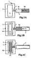
- FIG. 1 shows a tool mold 1 with a cavity 4, which is enclosed by a cavity wall 5.
- the cavity 4 is filled with heated thermoplastic molding material, such as suitable polyamide, to form the filter end disc.
- an opening 3 is provided in the mold 1, to which an extruder 2 is coupled, in which the plastic mold materials M1 and M2 can be filled.
- the material sequence M1 and M2 can be injected into the mold 1.
- Figure 1A shows a situation prior to injecting the two plastic mold materials M1, M2 in the mold 1.
- the first plastic molding material M1 which is to form an outer shell of the filter end later, is filled into the extruder 2 so that it is first injected through the opening 3 in FIG the cavity 4 of the tool mold 1 passes.
- a second plastic molding material M2 is provided, which likewise has polyamide, for example, which differs from the first material M1 by suitable additives, for example with regard to its radiation absorption properties.
- the materials M1 and M2 are filled in the extruder 2 so that they can be successively pressed into the opening 3 in the mold 1.
- the material M1 can also be selected, for example, as a water-impermeable material, such as polypropylene.
- a protective cover can be produced around the material M2, which is hydrophilic, ie hygroscopic. An unwanted storage of water during storage of the manufactured end plates is then prevented.
- modified polypropylene type Admer QB510E is used as M1 and polyamide as M2.
- FIG. 1B illustrates the injection process for the first plastic molding material M1, which is introduced into the tool mold 1 in the hot, substantially liquid state. Since at the edges or the surface 5 of the inner wall 5 in the cavity 4 of the mold 1 solidifies the first injected plastic molding material M1, the first plastic molding material M1 is substantially distributed around the inner wall 5. Only then is the second plastic molding material M2 through the opening 3 also injected or pressed into the mold 1.
- FIG. 1B shows the state, after which the first plastic molding material M1 has just been completely injected into the tool mold 1 and the second plastic molding material M2 passes through the opening 3. Thus, then the second plastic molding material M2 is also injected through the opening 3 in the mold 1.
- a cavity 6 may arise, in which the second plastic molding material M2, as in the Figure 1C is shown, passes.
- the two plastic mold materials M1, M2 in suitable dosage are now in the mold 1, wherein the second plastic mold material M2 forms a core of the resulting Filterendusion and the first plastic mold material M1 forms the outer surface.
- these factors can be such be set that result in a desired distribution of the materials in the interior 4 of the mold 1.
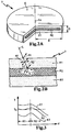
- FIG. 2 is a correspondingly produced Filterendusion 7 shown in more detail.
- the FIG. 2A shows a perspective view of an embodiment of a Filterendusion, for example, is designed substantially circular with a radius R and a thickness D.
- the filter end disk 7 has two materials, of which a first material M1 forms an outer shell and a second material M2 corresponds to a core of the filter end disk 7.
- the surface O of the filter end disk 7 therefore essentially has only the material M1.
- the material combination can be chosen such that the hygroscopic core M2 is encased by a moisture-shielding shell M1. Since commonly used polyamide is hygroscopic, and therefore absorbs moisture from the air, without the protective cover made of M1 to interfere with further processing steps. In a welding process, which is often necessary to connect the end plate 7 with a filter bellows, it can come in the presence of internal moisture to a blistering, which is undesirable. The water in the end plate component then foams up the liquid molten plastic molding material, and a secure and tight welding is hardly possible.
- the plastic molding materials may also have other functional properties that are advantageous for the further processing and production of filter elements are. In particular, it is possible to adjust the heat absorption properties in a targeted manner.
- FIG. 2B is a section of a cross section of the Filterendhari 7 shown.
- the materials M1 and M2 are selected, for example, such that the outer material M1 or the first plastic molding material M1 in the solidified state is different from the material M2 in terms of the heat transmission, absorption and reflection properties.
- the two materials are chosen such that the inner core material M2 converts an incident radiation into heat more strongly than the material M1.
- the water impermeability of the outer layer M1 may be present.
- infrared radiation L is indicated as an arrow, which is irradiated onto the filter end disk 7.
- the outer "protective layer” M1 ensures that after the production and storage of Endegonrohlinge no storage of water or moisture in the hygroscopic core material M2 can occur.
- these properties with respect to the irradiation of materials can be expressed by the degree of absorption A, the transmittance T and the reflectance R.
- a + T + R 1, which expresses the interdependence of the different processes in the material.
- the materials in the manufacturing process for a filter end disk are now chosen such that an incident radiation L, such as from an infrared radiator for a welding process, the second deeper material M2 present in the core of the Filterendhari 7 heated more than the superficially arranged plastic molding material M1.
- FIG. 3 is a temperature profile along, for example, an axis Ax of in FIG. 2 shown Filterendusion 7 shown at different Einstrahlungsdauem of infrared radiation.
- the depth d is illustrated on the X axis and the temperature curve T on the Y axis. Three curves are indicated, the upper curve K1 corresponding to the longest irradiation time and the curves K2 and K3 each having lower irradiation times of the plastic end disk.
- the melting temperature Ts is shown as a dashed line.
- the penetration depth d 0, for example, the surface O of the filter end disk 7 is present.
- the maximum temperature is in each case close to the interface between the two materials M1 and M2.
- the polyamide designated PA6 can be used as a suitable material for filter end discs.
- the outer material region M1 corresponds, for example, natural-colored polyamide
- the core region with the second plastic molding material M2 is made of polyamide which is colored black, for example with soot particles.
- Modified Admer QB510E polypropylene would also be suitable as a water-impermeable outer material. This results in a significantly higher absorption of the irradiated radiation by the core material M1, so that a higher temperature develops in the vicinity of the interface than in the surface region.
- the irradiation time can now be set such that at least the material M1 heats up in such a way that the melting point is reached.
- the curve K2 corresponds to a suitable irradiation time.
- the temperature in the first outer material M1 is very homogeneous and decreases only slightly towards the second material. This is advantageous since the corresponding filter fleece material is pressed into the molten material layer M1 and only to a small extent into the molten material layer M2 and is intended to form a fluid-tight seal.
- a filter end disc made of two components with an inner core and an outer layer, for example, produced in accordance with a monosandwich process, is therefore particularly well suited for efficiently and quickly forming filters.
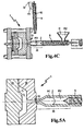
- FIGS. 4 and 5 an exemplary monosandwich process for the manufacture of a filter end disk is shown.
- the show Figures 4A-4C preparatory steps to fill an extruder with the appropriate plastic molding material mixture and the Figures 5A-5C various process conditions during the injection process of the two plastic molding materials.
- FIG. 4 is a tool mold 1 shown with a filler neck 13.
- the main extruder 2 is filled with the second plastic molding material M2, ie the material which causes a greater heat development upon irradiation in terms of heat absorption and Umsetz styleenschaften.
- the two extruders 2, 9 also have suitable transport screws 8, 10 or other means to transport the thermoplastic material M1 or M2 in the direction of the respective outlet opening. These are provided with the reference numerals 8 and 10.
- FIG. 4A is shown in detail, both extruders 2, 9 each completely filled with the plastic molding material M1, M2.
- the opening of the main extruder 2 is first connected to the opening of the secondary extruder 9. Subsequently, the first plastic molding material M1 is injected into a front region 20 of the main extruder 2. Thus, both the material mixture M1 and M2 as well as the sequence for a subsequent injection process results in the tool mold 1. The tip of the main extruder 2 is thus filled with the first plastic molding material M1. This is followed by the second plastic molding material M2.
- the secondary extruder 9 is separated, and the tip of the main extruder 2 is inserted into the filler neck 13 of the mold. This is in the FIG. 4C shown in more detail. It also follows that the two material sequences M1 and M2 are present in the front region of the tip 20 in accordance with their subsequent injection into the mold 1.
- FIG. 5 shows in more detail the injection process of the two materials M1 and M2 in the mold.
- the prepared extruder 2 is attached to the filler neck 13 of the mold 1.
- the tool mold 1 has two parts 1A and 1B, which together form an interior 4 with an interior wall 5.
- the extruder 2 has in the front region 20, the two materials M1 and M2, which are injected by a punch or other suitable conveyor 8, eg screw. Further, if thermoplastic material is used as the plastic molding material, the extruder syringe or the entire extruder 2 is heated accordingly.
- FIG. 5B shows the state in which the first plastic molding material M1 is already partially introduced into the mold 1 by the punch 8 in the extruder 2.
- the material M1 nestles substantially on the surface 5 of the inner wall in the interior 4 of the mold 1.
- the second plastic molding material M2 injected into the mold 1.
- the second plastic mold material remains essentially in the interior of the resulting filter end disk.
- the inner cavity 4 always has the same volume during the injection process. A shaping or distribution of the injected material by a change in the inner wall 5 does not take place. The cavity 4 and the shape of the tool 1A, 1B remain constant.
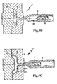
- FIG. 6 shows in more detail the processes when injecting the material mixture.
- FIG. 6 shows a cross section through the mold 1 with a respective surface 5.
- the surface 5 is relatively cool, so that when injecting the first plastic molding material M1 on the surface 5, the temperature drops below the melting point Ts, so that a layer M1S of solidified first plastic molding material M1S forms.
- the in the FIG. 6 Arrows shown represent the flow or injection direction of the plastic molding material M1 L in the liquid state. Since the cooling is not abrupt, the subsequent injection of the second plastic molding material M2 results in an inner region of the second plastic molding material M2.
- the geometry of the tool mold 1 and the injection speed are chosen such that the first and second plastic mold material do not mix, but as in the FIG. 6 1, the outer layer of the resulting filter end disk is made of the first material (M1S).
- FIG. 7 is a motor vehicle resource filter, for example, an oil or air filter with a filter end correspondingly manufactured, shown.
- the corresponding fluid filter 14 has upper and lower filter end disks 7A, 7B, for example, the upper filter end disk 7A has an opening 7C for introducing fluid such as fuel or air.
- Between the two Filterendharin 7A, 7B folded filter fabric material 15 is arranged in a cylindrical shape, which can for example be further held by suitable reinforcements 16 in the form.
- This is indicated by the arrows I and OT in the FIG. 7 indicated.
- the flow direction can of course also be done from outside to inside and thus the filtration from the outer jacket of the filter element.
- the respective filter end disk is heated on the side towards the filter material 15 so that a melt of the plastic molding material of the filter end disk 7A, 7B forms on the surface. Subsequently, the edge or the profile of the folded filter fabric is pressed into the melt, which then solidifies. As a rule, this results in good tight transitions.
- FIG. 8 a cross section through a corresponding fluid filter 14 is shown in fragmentary form. It is in the FIG. 8 illustrated the situation in which the filter medium 15, the molten material of the Filterendhari 7 was pressed in and solidified. You see in the FIG. 8 in that, when displacing the folding profiles into the filter end disk 7 between the folds and the filter end disk material, a tight seal is produced by the displacement. You see in the FIG. 8 Furthermore, that the second plastic molding material M2 can be melted by irradiation, whereby the penetration depth of the folds 15 is increased.
- the two materials M1 and M2 can be dyed the same color, without substantially changing their properties with respect to the heat conversion of incident radiation.
- the respective end plate can be additionally provided with a sealing element.
- FIG. 9 shows a truncated perspective view of another embodiment of a Filterendusion 7. It is on the front side, which in the orientation of the FIG. 9 facing up, a sealing element 19 is provided, which is formed exclusively of the outer plastic molding material M1.
- the sealing element 19 comprises two concentric rings 19 which protrude from the surface of the end plate 7.
- a meandering material web 20 is provided.
- the outer plastic mold material M1, which also comprises the sealing element 19, is preferably made of a softer plastic than the inner core material M2.
- the core material M2 is shown in black.
- This flexible seal geometry 19 can be adapted to the particular circumstances with regard to the folds to be attached thereto.
- the projecting webs 19, 20 are then melted and connect, as in the FIG. 8 is illustrated with the filter fleece. Due to the additional molten material of the sealing webs more plastic material can be connected to the fold profiles, and there is an improved seal between the folded fleece and the end plate.
- FIG. 10 schematically shows one for the production of in FIG. 9
- the tool 1A, 1B is in two parts and formed a constant cavity into which the plastic molding materials are injected.
- the second plastic molding material M2 forms the core of the filter end disk and is shown in black. It can be achieved by the design of the recesses particularly thin protruding from the disc sealing webs or sealing structures and thus save material.
- a plurality of concentric recesses are provided to provide many protruding sealing lands.
Landscapes
- Chemical & Material Sciences (AREA)
- Chemical Kinetics & Catalysis (AREA)
- Engineering & Computer Science (AREA)
- Manufacturing & Machinery (AREA)
- Mechanical Engineering (AREA)
- Filtering Materials (AREA)
- Injection Moulding Of Plastics Or The Like (AREA)
- Moulds For Moulding Plastics Or The Like (AREA)
Description
- Die vorliegende Erfindung betrifft ein Verfahren zum Herstellen einer Filterendscheibe, wie sie zum Beispiel für einen Fluidfilter bei einem Kraftfahrzeug benötigt wird. Häufig werden zylinderförmige Fluidfilter eingesetzt, bei denen zwischen zwei Filterendscheiben ein mit Längsfalten versehenes Filtermaterial angeordnet ist. Solche Filter dienen beispielsweise als Kraftstofffilter oder auch als Luftfilter im Pkw oder Lkw.
- Üblicherweise werden scheibenförmige Filterendplatten aus Kunststoff in einem Spritzgussverfahren gefertigt und anschließend mit einem Tubus aus gefaltetem Filtervliesmaterial verbunden. Dabei kann auf die ober- und unterseitigen Faltenprofile und/oder Endscheiben, zum Beispiel Klebstoff, aufgebracht werden, der einen fluiddichten Abschluss gewährleistet.
- Da teilweise insbesondere thermoplastische Kunststoffe für die Endscheiben verwendet werden, besteht auch die Möglichkeit, die filtermediumseitige Seite der Filterendplatte zu erhitzen, wodurch das Thermoplast schmilzt. In die teilweise angeschmolzene Filterendplatte wird dann das Faltenprofil hinein gedrückt, und es bildet sich nach erneutem Erstarren des Kunststoffmaterials ein möglichst dichter Abschluss. Ein Problem bei dem letztgenannten Verfahren ist die möglichst schnelle und dennoch gleichmäßige Erwärmung der Filter-end-platte, damit die Faltkanten hinein gedrückt werden können. Um einen fluiddichten Abschluss zu erzielen, muss zumindest eine gewisse Schichttiefe der Endplatte geschmolzen werden, was bei einer Serienproduktion von entsprechenden Fluidfiltem den Herstellungsprozess bremst.
- Beispielsweise ist aus der
EP 1 695 751 A1 ein Verfahren zum Herstellen einer Kunststoffendscheibe bekannt, bei welchem zwei im Wesentlichen planparallel zueinander angeordnete Kunststofflagen miteinander verschweißt werden, wobei eine Kunststofflage starr und die andere Kunststofflage elastisch ausgebildet ist. Außerdem ist beispielhaft der Fachartikel " Für alle Fälle gerüstet - Technologieführerschaft durch Mehrkomponententechnik" (Kunststoffe International, Vol. 92, Nr. 9, Seiten 105 - 109; Carl Hanser Verlag, München) zu nennen, welcher allgemein verschiedene Mehrkomponentenspritztechniken, insbesondere das sogenannte Monosandwich-Verfahren, beschreibt. - Es ist daher eine Aufgabe der vorliegenden Erfindung, ein verbessertes Verfahren zum Herstellen von Filterendscheiben bereitzustellen.
- Daher ist ein Verfahren zum Herstellen einer Filterendscheibe, wie zum Beispiel für einen Fluidfilter eines Kraftfahrzeuges, offenbart, wobei ein erstes Kunststoffformmaterial und ein zweites Kunststoffformmaterial gemäß einem Monosandwich-Verfahren oder Co-Injektionsverfahren derart in eine Werkzeugform gespritzt werden, dass das zweite Kunststoffformmaterial im Wesentlichen von dem ersten Kunststoffformmaterial umschlossen wird.
- Es hat sich das Monosandwich-Verfahren oder Co-Injektionsverfahren als besonders geeignet erwiesen, wobei das erste und das zweite Kunststoffformmaterial in die Werkzeugform gespritzt werden. Im Unterschied zu einem 2-Komponenten-Spritzguss erfolgt das Einbringen der beiden Komponenten bzw. Kunststoffformmaterialien mit einem Schneckenhub und nicht nacheinander mit 2 separaten Spritzaggregaten in einem Wendewerkzeug oder durch Umsetzen.
- Das innere Volumen der Werkzeugform, in die das erste und zweite Kunststoffformmaterial gespritzt wird, ist während des Einspritzens vorzugsweise konstant. Das heißt, dass die Werkzeugform hinsichtlich ihrer inneren Geometrie während des Monosandwich-Einspritztens oder Co-Injektions-Einspritzens nicht verändert wird. Bei einem zweiteiligen Werkzeug wird dasselbe zum Beispiel ausschließlich zum Entnehmen der gespritzten Filterendscheibe geöffnet.
- Bei konventionellen Spritzgussverfahren, die mehrkomponentige Spritzgussteile liefern, wird häufig die Form selbst während des Einspritzens verändert. Üblich sind zum Beispiel zylindrische Werkzeugformen deren inneres zylindrisches Volumen zum Verteilen der flüssigen eingespritzten Kunststoffformmassen verkleinert wird. Derartige ineinandergreifende stempelartige Werkzeuge sind bei dem vorgeschlagenen Verfahren nicht notwendig. Das Herstellungsverfahren ist daher schneller und einfacher zu implementieren.
- Das erste Kunststoffformmaterial ist bei einer Variante des Verfahrens im festen Zustand wasser- und/oder wasserdampfundurchlässig. Dadurch wird ein Schutz des zweiten Kunststoffformmaterials erreicht, welches in der Regel den inneren Kern der Endscheibe bildet. Falls das zweite Kunststoffformmaterial im festen Zustand hygroskopische Eigenschaften hat, wird eine Einlagerung von Wasser verhindert. Dies ist insbesondere von Vorteil, wenn das innere Kunststoffformmaterial in weiteren Prozessierungen erhitzt oder aufgeschmolzen werden muss, da Wasser ansonsten störende Blasen werfen könnte. Insofern werden die Lager- und Verarbeitungseigenschaften verbessert.
- Als inneres Kernmaterial, also zweites Kunststoffformmaterial, kann zum Beispiel Polyamid verwendet werden, welches einerseits einfach und günstig zu verarbeiten ist, andererseits jedoch wasseranziehend bzw. hygroskopisch ist. Durch die Wahl eines ersten wasserundurchlässigen Kunststoffformmaterials, wie zum Beispiel Polypropylen wird mittels dem Monosandwich-Verfahren oder Co-Injektionsverfahren eine geschlossene dichte Oberfläche erzielt. Das erste Kunststoffformmaterial umschließt dann zum Beispiel in der Art einer Folie oder Haut das zweite Kunststoffformmaterial.
- Die Kunststoffformmaterialien werden ferner vorzugsweise derart gewählt, dass das zweite Kunststoffformmaterial eine Strahlung mit vorgegebenen Strahlungseigenschaften stärker in Wärme umsetzt als das erste Kunststoffformmaterial.
- Bei einer weiteren Variante des Verfahrens ist die Werkzeugform derart geformt, dass beim Einspritzen das erste Kunststoffformmaterial in Aussparungen der Werkzeugform eindringt und diese derart ausfüllt, dass aus dem verfestigten ersten Kunststoffformmaterial ein von einer Stirnseite der Filterendscheibe abstehendes Dichtungselement entsteht.
- Die Aussparung in dem Formwerkzeug bzw. der Werkzeugform führt zum Beispiel zu einer Dichtlippe auf einer Stirnseite der fertigen Filterendscheibe. Es ist insbesondere vorteilhaft, wenn das von der Filterendscheibe abstehende Dichtungselement ausschließlich das erste Kunststoffformmaterial umfasst, und optional ferner das erste Kunststoffformmaterial im festen Zustand weicher und/oder flexibler ist als das zweite Kunststoffformmaterial im festen Zustand.
- Das sich ergebende Dichtelement wird bei der weiteren Verarbeitung zum Beispiel an- oder aufgeschmolzen, und der Rand oder das Faltenprofil eines zylinderförmigen Faltenpacks wird hineingedrückt und verbindet sich nach dem Erkalten fluiddicht.
- Bei einem Ausführungsbeispiel des Verfahrens und einer Filterendscheibe sind mehrere konzentrische, von der Filterendscheibe abstehende Dichtstege oder Dichtungslippen vorgesehen.
- Zum Beispiel bei der Verwendung von thermoplastischem Material als Kunststoffformmaterialien ergibt sich durch das nacheinander vollzogene Einspritzen in die Werkzeugform, dass das erste Kunststoffformmaterial an den Innenwänden der Werkzeugform beim Einspritzvorgang erstarrt und im Wesentlichen das zweite Kunststoffformmaterial einen inneren Kern der derart gefertigten Filterendscheibe bildet. Durch die Auswahl der beiden Kunststoffformmaterialien mit vorgegebenen Eigenschaften hinsichtlich der energetischen Umsetzung einer eingestrahlten Strahlung in Wärmeenergie kann eine besonders günstige, erneute Aufschmelzung der Filterendscheibe in weiteren Verarbeitungsschritten zum Ausbilden eines vollständigen Fluidfilters erzielt werden.
- Insbesondere Polyamid als thermoplastisches Material eignet sich als Filterendscheibenmaterial und zum Einspritzen in eine Werkzeugform. Um die gewünschten Absorptions-, Reflektions- und Transmissionseigenschaften der beiden Kunststoffformmaterialien zu erzielen, kann zum Beispiel das erste Kunststoffformmaterial derart gewählt werden, dass es einen niedrigeren Absorptionsgrad hat als das zweite Kunststoffformmaterial. Das erste Kunststoffformmaterial hat vorzugsweise ferner einen niedrigeren Reflektionsgrad als das zweite Kunststoffformmaterial. Das erste Kunststoffformmaterial kann zudem einen höheren Transmissionsgrad als das zweite Kunststoffformmaterial haben. Dabei versteht sich der Absorptions-, Reflektions- und Transmissionsgrad jeweils bezüglich einer vorgegebenen Strahlung.
- Die Strahlung kann zum Beispiel Wärmestrahlung von einem Infrarotstrahler z.B. Laser, Glühwendel oder Leuchtdiodenarray sein. Als mögliche Wellenlängen der Infrarot-Strahlung kommen 780 bis 3000 nm insbesondere 900 nm bis 1500 nm oder auch schmalbandiger 900 nm bis 1100 nm in Frage, die auch bei üblichen Schweißverfahren mit Kunststoff Ver wendung finden.
- Dadurch, dass das äußere erste Kunststoffformmaterial im Wesentlichen transparenter ist, dringt eine eingestrahlte Wärmestrahlung zunächst durch die äußere Oberfläche der Filterendscheibe hindurch und erhitzt dann an der Grenzfläche zwischen den beiden Kunststoffformmaterialien einen unterhalb der Oberfläche liegenden Bereich der Filterendscheibe. Dadurch ergibt sich eine besonders günstige Temperaturprofileinstellung, was es erleichtert, zum Beispiel ein Filtermaterial mit der Filterendscheibe zu verbinden.
- In einer Variante des Verfahrens erfolgt ferner ein Einfärben des ersten und des zweiten Kunststoffformmaterials derart, dass die jeweiligen Absorptions-, Reflektions- und/oder Transmissionseigenschaften für die Strahlung im Wesentlichen unverändert bleiben. Die Kunststoffformmaterialien weisen jedoch dennoch dieselbe Farbe auf. Dadurch kann visuell nicht erkannt werden, dass die Filterendscheibe aus zwei Komponenten, nämlich dem ersten und dem zweiten Kunststoffformmaterial aufgebaut ist. Es existieren insbesondere geeignete Farbstoffe, die transparent für Infrarotstrahlung sind und somit praktisch keinen Einfluss auf das Temperaturprofil senkrecht zu einer Oberfläche der Filterendscheibe haben.
- Das zweite Kunststoffformmaterial kann zum Beispiel aus dem ersten Kunststoffformmaterial gebildet werden, indem Rußpartikel zum Erhöhen des Absorptionsgrades beigefügt werden. Dies hat zum Beispiel den Vorteil, dass sich die rheologischen Eigenschaften beider Kunststoffformmaterialien unwesentlich unterscheiden und eine Verarbeitung, beispielsweise in der Spritzgussmaschine besonders leicht ist.
- Es wird ferner ein Verfahren zum Herstellen eines Fluidfilters vorgeschlagen. Dabei wird zunächst ein wie zuvor angedeutetes Verfahren zum Herstellen einer Filterendscheibe durchgeführt. Anschließend erfolgt ein Bestrahlen der Filterendscheibe durch eine Strahlung mit den vorgegebenen Strahlungseigenschaften zum Schmelzen des ersten Kunststoffformmaterials. Dann wird ein Filtermaterial auf das zumindest teilweise geschmolzene erste Kunststoffformmaterial aufgebracht. Beispielsweise kann ein gefalteter Rand des Filtermaterials in das geschmolzene erste Kunststoffformmaterial hinein gedrückt werden.
- Die vorliegende Erfindung umfasst ferner einen Kraftfahrzeugfluidfilter, welcher nach dem zuvor offenbarten Verfahren hergestellt ist.
- Ferner wird eine Filterendscheibe, insbesondere für einen Fluidfilter eines Kraftfahrzeugs, welche nach einem Monosandwichverfahren oder Co-Injektionsverfahren gefertigt ist, beansprucht. Dabei ist ein erstes äußeres Kunststoffformmaterial und ein zweites inneres Kunststoffformmaterial vorgesehen, wobei das zweite Kunststoffformmaterial von dem ersten Kunststoffformmaterial umschlossen ist. Das erste Kunststoffformmaterial ist dann wasser- und/oder wasserdampfundurchlässig.
- Das zweite Kunststoffformmaterial kann, wie zum Beispiel Polyamid, hygroskopisch sein, und das erste Kunststoffformmaterial kann, wie zum Beispiel modifiziertes Polypropylen, wasserundurchlässig sein. Die beiden Kunststoffformmaterialien sind derart ausgewählt, dass sie insbesondere in einem Monosandwichverfahren verarbeitbar sind und in der Filterendscheibe aneinander haften.
- Insofern bildet das erste Kunststoffformmaterial vorzugsweise eine geschlossene wasserund/oder wasserdampfdichte äußere Oberfläche der Filterendscheibe.
- Erfindungsgemäß ist auch eine Filterendscheibe mit einem ein ersten äußeren Kunststoffformmaterial und einem zweiten inneren Kunststoffformmaterial, wobei das zweite Kunststoffformmaterial von dem ersten Kunststoffformmaterial umschlossen ist. Die Umschließung kann hierbei vollständig sein, insbesondere wenn das erste Kunststoffformmaterial wasserdampfdicht ist, oder in alternativen Ausgestaltungen auch nur teilweise vorliegen, z.B. an einer flachen Seite der Filterendscheibe zu 50% der Fläche, bevorzugt zu mehr als 90% der Fläche vorliegen.
- Das erste Kunststoffformmaterial kann bei der Filterendscheibe in einem Wellenlängenbereich, z.B. Infrarot, eine geringere Absorption besitzen als das zweite Kunststoffmaterial. Beim Bestrahlen mit dieser Wellenlänge wird dann der Kern oder das zweite Kunststoffmaterial stärker erwärmt als das äußere Kunststoffmaterial, das den Kern umschließt. Das erste, äußere Kunststoffmaterial kann einen niedrigeren Erweichungspunkt oder Schmelzpunkt besitzen als das zweite, innere Kunststoffmaterial. In jedem Fall kann durch die Erwärmung des zweiten, inneren Kunststoffmaterials das erste, äußere Kunststoffmaterial so erwärmt werden, dass eine Verbindung mit einem Faltenbalg ermöglicht wird.
- Eine besonders starke Erwärmung kann z.B. an einer der Grenzflächen vom ersten Kunststoffmaterial mit dem zweiten Kunststoffmaterial auf der Seite des zweiten Kunststoffmaterials realisiert werden.
- Weiterhin umfasst die vorliegende Erfindung einen Kraftfahrzeugfluidfilter mit einer Filterendscheibe wie in den verschiedenen Ausführungsformen beschrieben. Insbesondere einen Kraftfahrzeugfluidfilter mit einem Faltenbalg, insbesondere einem sterngefalteten Faltenbalg. Insbesondere umfasst die Erfindung einen Öl- oder Kraftstofffilter mit einer oder mehreren beschriebenen Filterendscheiben.
- Weitere mögliche Implementierungen der Erfindung umfassen auch nicht explizit genannte Kombinationen von zuvor oder im Folgenden bezüglich der Ausführungsbeispiele beschriebenen Merkmale, Verfahrensschritte oder Ausführungsformen. Dabei wird der Fachmann auch Einzelaspekte als Verbesserungen oder Ergänzungen zu der jeweiligen Grundform der Erfindung hinzufügen.
- Weitere Ausgestaltungen der Erfindung sind Gegenstand der Unteransprüche sowie der im Folgenden beschriebenen Ausführungsbeispiele.
- Im Weiteren wird die Erfindung anhand beispielhafter Ausführungsformen unter Bezugnahme auf die beigelegten Figuren näher erläutert. Es zeigt dabei:
-
Figur 1 : eine Abfolge von Verfahrensschritten zum Herstellen einer Filterendscheibe; -
Figur 2 : eine perspektivische Ansicht einer Filterendscheibe und deren Strahlungsabsorptionseigenschaften; -
Figur 3 : ein Diagramm zur Erläuterung des Temperaturprofils bei Wärmeeinstrahlung auf eine Filterendscheibe; -
Figur 4 : eine Schnittansicht eines Spritzgusswerkzeuges für ein Monosandwich-Verfahren zum Herstellen einer Filterendscheibe; -
Figur 5 : eine Darstellung des Spritzgusswerkzeuges während eines Einspritzvorganges nach einem Monosandwich-Verfahren; -
Figur 6 : eine detaillierte Schnittansicht während eines Einspritzvorgangs einer zweikomponentigen Kunststoffformmasse; -
Figur 7 : eine perspektivische Ansicht eines Kraftfahrzeugfluidfilters; -
Figur 8 : eine Schnittansicht eines Kraftfahrzeugfluidfilters; -
Figur 9 : eine angeschnittene perspektivische Ansicht einer Filterendscheibe; und -
Figur 10 : eine Schnittansicht eines weiteren Spritzgusswerkzeuges für ein MonosandwichVerfahren zum Herstellen einer Filterendscheibe. - In den Figuren sind gleiche oder funktionsgleiche Elemente mit denselben Bezugszeichen versehen worden, sofern nichts anderes angegeben ist.
- In der
Figur 1 sind Verfahrensschritte für ein Verfahren zum Herstellen einer Filterendscheibe dargestellt.Figur 1 zeigt eine Werkzeugform 1 mit einem Hohlraum 4, der von einer Hohlraumwandung 5 umschlossen ist. Der Hohlraum 4 wird mit erhitztem thermoplastischem Kunststoffformmaterial, wie beispielsweise geeignetem Polyamid ausgefüllt zum Ausbilden der Filterendscheibe. Dazu ist in der Werkzeugform 1 eine Öffnung 3 vorgesehen, an die ein Extruder 2 angekoppelt ist, in den die Kunststoffformmaterialien M1 und M2 eingefüllt werden können. Beispielsweise mit einem Stempel oder Schnecke oder einer anderen geeignete Fördereinrichtung kann die Materialabfolge M1 und M2 in die Werkzeugform 1 gespritzt werden. -
Figur 1A zeigt eine Situation vor dem Einspritzen der beiden Kunststoffformmaterialien M1, M2 in die Werkzeugform 1. Das erste Kunststoffformmaterial M1, welches später eine Außenhülle der Filterendscheibe bilden soll, ist derart in den Extruder 2 eingefüllt, dass es beim Einspritzen als erstes durch die Öffnung 3 in den Hohlraum 4 der Werkzeugform 1 gelangt. Hinter dem ersten Kunststoffformmaterial M1 ist ein zweites Kunststoffformmaterial M2 vorgesehen, das beispielsweise ebenfalls Polyamid aufweist, das sich durch geeignete Zusätze zum Beispiel hinsichtlich seiner Strahlungsabsorptionseigenschaften von dem ersten Material M1 unterscheidet. Die Materialien M1 und M2 sind so in den Extruder 2 eingefüllt, dass sie nacheinander in die Öffnung 3 in die Werkzeugform 1 gepresst werden können. - Das Material M1 kann beispielsweise auch als wasserundurchlässiges Material, wie Polypropylen, gewählt werden. Dadurch kann, wie im Weiteren erläutert ist, eine Schutzhülle um das Material M2 erzeugt werden, welches wasseranziehend, also hygroskopisch ist. Eine ungewünschte Einlagerung von Wasser bei der Lagerung der hergestellten Endscheiben wird dann verhindert. Um eine Verträglichkeit der beiden Kunststoffformmaterialien M1, M2 miteinander mit den gewählten Eigenschaften zu gewährleisten, wird beispielsweise modifiziertes Polypropylen vom Typ Admer QB510E als M1 und Polyamid als M2 verwendet.
- Die
Figur 1B illustriert den Einspritzvorgang für das erste Kunststoffformmaterial M1, welches im heißen, im Wesentlichen flüssigen Zustand, in die Werkzeugform 1 eingeführt wird. Da sich an den Rändern bzw. der Oberfläche 5 der Innenwandung 5 im Hohlraum 4 der Werkzeugform 1 das als erstes eingespritzte Kunststoffformmaterial M1 erstarrt, verteilt sich das erste Kunststoffformmaterial M1 im Wesentlichen um die Innenwandung 5. Erst anschließend wird das zweite Kunststoffformmaterial M2 durch die Öffnung 3 ebenfalls in die Werkzeugform 1 eingespritzt oder eingepresst.Figur 1B zeigt den Zustand, nach dem das erste Kunststoffformmaterial M1 gerade vollständig in die Werkzeugform 1 eingespritzt wurde und das zweite Kunststoffformmaterial M2 durch die Öffnung 3 gelangt. Somit wird dann das zweite Kunststoffformmaterial M2 ebenfalls durch die Öffnung 3 in die Werkzeugform 1 eingespritzt. - Durch das bereits erfolgte Erstarren des ersten Kunststoffformmaterials M1 an der Innenwandung 5 kann ein Hohlraum 6 entstehen, in den das zweite Kunststoffformmaterial M2, wie es in der
Figur 1C dargestellt ist, gelangt. Die beiden Kunststoffformmaterialien M1, M2 in geeigneter Dosierung, sind nun in der Werkzeugform 1, wobei das zweite Kunststoffformmaterial M2 einen Kern der sich ergebenden Filterendscheibe bildet und das erste Kunststoffformmaterial M1 die äußere Oberfläche bildet. Hinsichtlich der Anordnung der Werkzeugform 1 und dem Extruder 2 sowie der Einspritzgeschwindigkeiten der beiden nacheinander eingeführten Kunststoffformmaterialien M1, M2, können diese Faktoren derart eingestellt werden, dass sich eine gewünschte Verteilung der Materialien im Innenraum 4 der Werkzeugform 1 ergeben. - In der
Figur 2 ist eine entsprechend hergestellte Filterendscheibe 7 näher dargestellt. DieFigur 2A zeigt eine perspektivische Ansicht einer Ausführungsform einer Filterendscheibe, die beispielsweise im Wesentlichen kreisrund mit einem Radius R und einer Dicke D ausgeführt ist. Die Filterendscheibe 7 weist zwei Materialien auf, wovon ein erstes Material M1 eine Außenhülle bildet und ein zweites Material M2 einem Kern der Filterendscheibe 7 entspricht. Die Oberfläche O der Filterendscheibe 7 hat daher im Wesentlichen lediglich das Material M1. - Zum Einen kann die Materialkombination derart gewählt werden, dass der hygroskopische Kern M2 von einer Feuchtigkeits-abschirmenden Hülle M1 ummantelt ist. Da häufig verwendetes Polyamid hygroskopisch ist, und daher Feuchtigkeit aus der Luft aufnimmt, kommt es ohne die Schutzhülle aus M1 zu Störungen in weiteren Verarbeitungsschritten. In einem Schweißprozess, der oft notwendig ist, um die Endscheibe 7 mit einem Filterbalg zu verbinden, kann es bei vorliegender innerer Feuchtigkeit zu einer Blasenbildung kommen, die unerwünscht ist. Das Wasser im Endscheibenbauteil schäumt dann das flüssige geschmolzene kunststoffformmaterial auf, und eine sichere und dichte Verschweißung ist kaum noch möglich.
- In der Vergangenheit mussten vorgefertigte Endscheiben daher aufwändig getrocknet werden. Diese sonst notwendigen zusätzlichen Maßnahmen sind bei der vorgeschlagenen Variante, bei der das erste im Monosandwichverfahren eingespritzte Kunststoffformmaterial wasser- oder wasserdampfundurchlässig ist, nicht notwendig. Entsprechende geeignete Materialien sind zum Beispiel aus der Kunststofffolienherstellung bekannt.
- Zum Anderen können die Kunststoffformmaterialien auch weitere funktionelle Eigenschaften aufweisen, die für die Weiterverarbeitung und Herstellung von Filterelementen von Vorteil sind. Es ist insbesondere möglich, die Wärmeabsorptionseigenschaften gezielt einzustellen.
- In der
Figur 2B ist ein Ausschnitt eines Querschnittes der Filterendscheibe 7 dargestellt. Dabei ergibt sich eine Abfolge von Materialschichten zu M1, M2 und M1. Die Materialien M1 und M2 sind beispielsweise derart gewählt, dass das äußere Material M1 bzw. das erste Kunststoffformmaterial M1 im erstarrten Zustand hinsichtlich der Wärmetransmissions-, Absorptions- und Reflektionseigenschaften unterschiedlich von dem Material M2 ist. Die beiden Materialien sind derart gewählt, dass das innere Kernmaterial M2 stärker eine einfallende Strahlung in Wärme umsetzt als das Material M1. Darüber hinaus kann die Wasserundurchlässigkeit der äußeren Schicht M1 vorliegen. - Zur Erläuterung ist beispielsweise Infrarotstrahlung L als Pfeil angedeutet, welches auf die Filterendscheibe 7 eingestrahlt wird. Beispielsweise ist es notwendig, bis zu einer gewissen Tiefe, die Materialien M1 und M2 aufzuschmelzen, um in das angeschmolzene Kunststoffmaterial, ein gefaltetes Filtervlies-Material als Filtermedium, hineinzudrücken und mit der Filterendscheibe 7 zu verbinden. Dabei ist es insbesondere gewünscht, dass ein etwa 1-2 mm tiefer Bereich von der Oberfläche der Filterendscheibe aus betrachtet aufgeschmolzen wird. Dies muss möglichst schnell erfolgen, um den Herstellungsprozess der sich ergebenden Filter zu beschleunigen.
- Sofern keine Feuchtigkeit in dem inneren Material M2 vorliegt, lässt sich ein gut kontrollierbares Aufschmelzen erreichen. Ansonsten würden Blasen und Schaum entstehen, der die weitere Bearbeitung stört. Die äußere "Schutzschicht" M1 gewährleistet, dass nach der Herstellung und Lagerung der Endscheibenrohlinge keine Einlagerung von Wasser oder Feuchtigkeit in das hygroskopische Kernmaterial M2 auftreten kann.
- Im Wesentlichen ergeben sich drei Prozesse, wenn Strahlung auf ein Material eingestrahlt wird. Einerseits werden Teile der eingestrahlten Strahlung L reflektiert. Dies ist an der Grenzfläche zwischen beispielsweise Luft und dem ersten Material M1 durch den Pfeil R1 angedeutet. An der Grenzfläche zwischen den Materialien M1 und M2 kann ebenfalls Reflektion auftreten, was durch den Pfeil R2 dargestellt ist. Darüber hinaus können ebenfalls Anteile des Lichtes oder der Strahlung L das jeweilige Material durchlaufen oder transmittieren. Dies wird durch den Pfeil T1 bzw. T2 in der Zeichnung und auch allgemein durch einen Transmissionsgrad ausgedrückt. Darüber hinaus ergibt sich eine Absorption in den Materialien beim Durchlauf der Strahlung. Die Pfeile A1 illustrieren die Absorption im oberen Material M1 und die Pfeile A2, die gestrichelt dargestellt sind, die Absorption der Strahlung im Material M2. Wie bereits eingangs angedeutet wurde, können diese Eigenschaften hinsichtlich der Bestrahlung von Materialien durch den Absorptionsgrad A, den Transmissionsgrad T und den Reflektionsgrad R ausgedrückt werden. Es ergibt sich zum Beispiel der Zusammenhang: A + T + R = 1, was die wechselseitige Abhängigkeit der verschiedenen Prozesse im Material ausdrückt.
- Die Materialien im Herstellungsverfahren für eine Filterendscheibe sind nun derart gewählt, dass eine einfallende Strahlung L, wie beispielsweise von einem Infrarotstrahler für ein Schweißverfahren, das zweite tiefer liegende im Kern der Filterendscheibe 7 vorliegende Material M2 stärker erhitzt als das oberflächlich angeordnete Kunststoffformmaterial M1.
- In der
Figur 3 ist ein Temperaturverlauf entlang beispielsweise einer Achse Ax der inFigur 2 dargestellten Filterendscheibe 7 bei verschiedenen Einstrahlungsdauem von Infrarotstrahlung dargestellt. Auf der X-Achse ist die Tiefe d illustriert und auf der Y-Achse der Temperaturverlauf T. Dabei sind drei Kurven angedeutet, wobei die obere Kurve K1 der längsten Bestrahlungszeit entspricht und die Kurven K2 und K3 jeweils geringere Bestrahlungszeiten der Kunststoffendscheibe haben. Es ist die Schmelztemperatur Ts als gestrichelte Linie dargestellt. Ferner ergeben sich zwei Abschnitte M1 und M2, die den beiden Materialien entsprechen. Bei einer Eindringtiefe d = 0 liegt beispielsweise die Oberfläche O der Filterendscheibe 7 vor. - Man erkennt, dass die maximale Temperatur jeweils in der Nähe der Grenzfläche zwischen den beiden Materialien M1 und M2 vorliegt. Dadurch kann z.B. die Grenzfläche schnell erwärmt werden und aufschmelzen ohne die Oberfläche zu "verbrennen". Beispielsweise kann das Polyamid mit der Bezeichnung PA6 als geeignetes Material für Filterendscheiben verwendet werden. Der äußere Materialbereich M1 entspricht dabei beispielsweise naturfarbenem Polyamid, während der Kernbereich mit dem zweiten Kunststoffformmaterial M2 aus Polyamid, das schwarz, beispielsweise mit Rußpartikeln eingefärbt ist. Auch modifiziertes Polypropylen vom Typ Admer QB510E wäre als wasserundurchlässiges äußeres Material geeignet. Somit ergibt sich eine deutlich höhere Absorption der eingestrahlten Strahlung durch das Kernmaterial M1, so dass sich in der Nähe der Grenzfläche eine höhere Temperatur entwickelt als im Oberflächenbereich.
- Die Bestrahlungsdauer kann nun derart eingestellt werden, dass sich zumindest das Material M1 derart aufheizt, dass der Schmelzpunkt erreicht wird. Die Kurve K2 entspricht beispielsweise gerade einer geeigneten Bestrahlungszeit. Man erkennt aus der
Figur 3 ferner, dass die Temperatur in dem ersten äußeren Material M1 sehr homogen vorliegt und nur unwesentlich in Richtung zu dem zweiten Material abnimmt. Dies ist von Vorteil, da in die aufgeschmolzene Materialschicht M1 und nur zu geringem Anteil in die geschmolzene Materialschicht M2 das entsprechende Filtervlies-Material eingedrückt wird und einen fluiddichten Abschluss bilden soll. - Eine beispielsweise gemäß einem Monosandwich-Verfahren hergestellte Filterendscheibe aus zwei Komponenten mit einem inneren Kern und einer äußeren Schicht, ist daher besonders gut geeignet, effizient und schnell Filter auszubilden.
- In den
Figuren 4 und5 ist ein beispielhaftes Monosandwich-Verfahren für die Herstellung einer Filterendscheibe dargestellt. Dabei zeigen dieFiguren 4A-4C vorbereitende Schritte, um einen Extruder mit der geeigneten Kunststoffformmaterialmischung zu befüllen und dieFiguren 5A-5C verschiedene Prozesszustände während des Einspritzvorganges der beiden Kunststoffformmaterialien. - In der
Figur 4 ist eine Werkzeugform 1 mit einem Einfüllstutzen 13 dargestellt. Es sind ferner zwei Extruder 2, 9 vorgesehen, wobei der Extruder 2, welcher in derFigur 4 horizontal angeordnet ist, der Hauptextruder ist. An die beiden Extruder 2, 9 sind Materialreservoirs 11, 12 angekoppelt, die das jeweilige Kunststoffformmaterial M2 und M1 aufweisen. Der Hauptextruder 2 ist dabei mit dem zweiten Kunststoffformmaterial M2 befüllbar, also das Material, welches hinsichtlich der Wärmeabsorption und Umsetzeigenschaften eine stärkere Wärmeentwicklung bei Bestrahlung hervorruft. Die beiden Extruder 2, 9 haben ferner geeignete Transportschnecken 8, 10 oder andere Einrichtungen, um das thermoplastische Material M1 bzw. M2 in Richtung der jeweiligen Austrittsöffnung zu transportieren. Diese sind mit den Bezugszeichen 8 und 10 versehen. Zunächst sind, wie inFigur 4A näher dargestellt ist, beide Extruder 2, 9 jeweils vollständig mit dem Kunststoffformmaterial M1, M2 gefüllt. - Wie in der
Figur 4B dargestellt ist, wird zunächst die Öffnung des Hauptextruders 2 mit der Öffnung des sekundären Extruders 9 verbunden. Anschließend wird in einen vorderen Bereich 20 des Hauptextruders 2 das erste Kunststoffformmaterial M1 eingespritzt. Somit ergibt sich sowohl die Materialmischung M1 und M2 wie auch die Abfolge für einen darauf folgenden Einspritzvorgang in die Werkzeugform 1. Die Spitze des Hauptextruders 2 ist somit mit dem ersten Kunststoffformmaterial M1 gefüllt. Daran schließt sich das zweite Kunststoffformmaterial M2 an. - Anschließend wird der sekundäre Extruder 9 getrennt, und die Spitze des Hauptextruders 2 wird in den Einfüllstutzen 13 der Werkzeugform eingesetzt. Dies ist in der
Figur 4C näher dargestellt. Es ergibt sich auch, dass im vorderen Bereich der Spitze 20 die beiden Materialabfolgen M1 und M2 gemäß ihrem anschließenden Einspritzen in die Werkzeugform 1 vorliegen. - Die
Figur 5 zeigt detaillierter den Einspritzvorgang der beiden Materialien M1 und M2 in die Werkzeugform. - In der
Figur 5A ist der vorbereitete Extruder 2 an den Einfüllstutzen 13 der Werkzeugform 1 angesetzt. Die Werkzeugform 1 weist zwei Teile 1A und 1B auf, die gemeinsam einen Innenraum 4 mit einer Innenraumwandung 5 bilden. Der Extruder 2 hat im vorderen Bereich 20 die beiden Materialien M1 und M2, welche durch einen Stempel oder eine andere geeignete Fördereinrichtung 8, z.B. Schnecke, eingespritzt werden. Ferner wird, falls thermoplastisches Material als Kunststoffformmaterial verwendet wird, die Extruderspritze oder der gesamte Extruder 2 entsprechend aufgeheizt. - Die
Figur 5B zeigt den Zustand, in dem das erste Kunststoffformmaterial M1 durch den Stempel 8 im Extruder 2 bereits teilweise in die Werkzeugform 1 eingeführt ist. Dabei schmiegt sich das Material M1 im Wesentlichen an der Oberfläche 5 der Innenwandung im Innenraum 4 die Werkzeugform 1 an. - Schließlich wird, wie in der
Figur 5C dargestellt ist, auch das zweite Kunststoffformmaterial M2 in die Werkzeugform 1 eingespritzt. Durch das Abkühlen und Erstarren des ersten Kunststoffformmaterials an der Werkzeugforminnenwandung 5, verbleibt das zweite Kunststoffformmaterial im Wesentlichen im Inneren der sich ergebenden Filterendscheibe. - Man erkennt, dass die Werkzeugform 1A, 1 B selbst nicht bewegt oder verändert wird. Der innere Hohlraum 4 hat während des Einspritzvorgangs immer dasselbe Volumen. Ein Formung oder Verteilung des eingespritzten Materials durch eine Veränderung der Innenwandung 5 erfolgt nicht. Der Hohlraum 4 und die Form des Werkzeugs 1A, 1 B bleibt konstant.
- Die
Figur 6 zeigt etwas detaillierter die Vorgänge beim Einspritzen der Materialmischung.Figur 6 zeigt einen Querschnitt durch die Werkzeugform 1 mit einer jeweiligen Oberfläche 5. Die Oberfläche 5 ist relativ kühl, so dass beim Einspritzen des ersten Kunststoffformmaterials M1 an der Oberfläche 5 die Temperatur unterhalb des Schmelzpunktes Ts sinkt, so dass sich eine Schicht M1S von gefestigtem ersten Kunststoffformmaterial M1S bildet. Die in derFigur 6 dargestellten Pfeile stellen die Fließ- bzw. Einspritzrichtung des Kunststoffformmaterials M1 L im flüssigen Zustand dar. Da das Abkühlen nicht abrupt erfolgt, ergibt sich beim nachfolgenden Einspritzen des zweiten Kunststoffformmaterials M2 ein innerer Bereich aus dem zweiten Kunststoffformmaterial M2. Die Geometrie der Werkzeugform 1 und die Einspritzgeschwindigkeit sind derart gewählt, dass sich das erste und zweite Kunststoffformmaterial nicht vermischen, sondern wie in derFigur 6 dargestellt ist, die äußere Schicht der sich ergebenden Filterendscheibe aus dem ersten Material besteht (M1S). - In der
Figur 7 ist ein Kraftfahrzeugbetriebsmittelfilter, beispielsweise ein Öl- oder Luftfilter mit einer entsprechend hergestellten Filterendscheibe, dargestellt. Das entsprechende Fluidfilter 14 hat eine obere und eine untere Filterendscheibe 7A, 7B, wobei beispielsweise die obere Filterendscheibe 7A eine Öffnung 7C zum Einführen von Fluid, wie beispielsweise Kraftstoff oder Luft aufweist. Zwischen den beiden Filterendscheiben 7A, 7B ist gefaltetes Filtervlies-Material 15 zylinderförmig angeordnet, das beispielsweise ferner durch geeignete Verstärkungen 16 in Form gehalten werden kann. - Eine entsprechende Filterung von einströmendem Fluid I in den Innenraum des sich ergebenden Zylinders aus dem Filtermaterial 15, tritt durch das Filtermaterial als gereinigtes Fluid OT aus. Dies ist durch die Pfeile I und OT in der
Figur 7 angedeutet. Die Flussrichtung kann selbstverständlich auch von Außen nach Innen erfolgen und damit die Filtration vom Außenmantel des Filterelements aus. Um die Filterendscheiben 7A und 7B mit dem Filtermaterial 5 fluiddicht zu verbinden, wird wie zuvor angedeutet, die jeweilige Filterendscheibe auf der Seite zum Filtermaterial 15 hin erwärmt, so dass sich an der Oberfläche eine Schmelze des Kunststoffformmaterials der Filterendscheibe 7A, 7B bildet. Anschließend wird die Kante oder das Profil des gefalteten Filtervlies in die Schmelze gedrückt, welche anschließend erstarrt. In der Regel ergeben sich dadurch gute dichte Übergänge. - In der
Figur 8 ist ein Querschnitt durch ein entsprechendes Fluidfilter 14 ausschnittweise dargestellt. Dabei ist in derFigur 8 die Situation dargestellt, in der das Filtermedium 15, das angeschmolzene Material der Filterendscheibe 7 hineingedrückt wurde und erstarrt ist. Man sieht in derFigur 8 , dass durch das Verdrängen beim Hineindrücken der Faltprofile in die Filterendscheibe 7 zwischen den Faltungen und dem Filterendscheibenmaterial ein dichter Abschluss entsteht. Man sieht in derFigur 8 ferner, dass auch das zweite Kunststoffformmaterial M2 durch Bestrahlung angeschmolzen werden kann, wodurch die Eindringtiefe der Faltungen 15 erhöht wird. - Damit eine entsprechende Filterendscheibe und der resultierende Kraftfahrzeugfilter auch den ästhetischen Ansprüchen der Kunden entspricht, können die beiden Materialien M1 und M2 gleichfarbig eingefärbt werden, ohne deren Eigenschaften hinsichtlich der Wärmeumsetzung von eingestrahlter Strahlung wesentlich zu ändern.
- Um die Dichtung zwischen den Faltenprofilkanten und den Endscheiben 7A, 7B zu verbessern, kann die jeweilige Endscheibe zusätzlich mit einem Dichtungselement versehen werden.
- Die
Figur 9 zeigt eine angeschnittene perspektivische Ansicht einer weiteren Ausführungsform einer Filterendscheibe 7. Dabei ist an der Stirnseite, welche in der Orientierung derFigur 9 nach oben weist, ein Dichtungselement 19 vorgesehen, welches ausschließlich aus dem äußeren Kunststoffformmaterial M1 gebildet ist. Das Dichtungselement 19 umfasst zwei konzentrische Ringe 19, die von der Fläche der Endscheibe 7 abstehen. Dazwischen ist ein geschlängelter Materialsteg 20 vorgesehen. Das äußere Kunststoffformmaterial M1, welches auch die das Dichtungselement 19 umfasst, ist vorzugsweise aus einem weicheren Kunststoff als das innere Kernmaterial M2. Das Kernmaterial M2 ist schwarz dargestellt. Diese flexible Dichtungsgeometrie 19 kann an die jeweiligen Gegebenheiten hinsichtlich der darauf anzubringenden Faltungen angepasst werden. Die abstehenden Stege 19, 20 werden dann geschmolzen und verbinden sich, wie es in derFigur 8 illustriert ist, mit dem Filtervlies. Durch das zusätzliche aufgeschmolzene Material der Dichtungsstege kann mehr Kunststoffmaterial mit den Faltenprofilen verbunden werden, und es entsteht eine verbesserte Abdichtung zwischen dem Faltenvlies und der Endscheibe. - Es wird also eine Endscheibe 7 mit integrierter Dichtung geschaffen, wobei das äußere Material in der Regel höherwertiger und teuerer ist. Durch die Herstellung in einem Monosandwich- oder Co-Injektionsverfahren wird der erhöhte Einsatz von geringerwertigem Kernmaterial aufwandsgünstig möglich.
- Die
Figur 10 zeigt schematisch eine für die Herstellung der inFigur 9 dargestellten Ausführungsform für eine Filterendscheibe geeignet ausgestaltete Werkzeugform 1. Das Werkzeug 1A, 1B ist zweiteilig und bildete einen konstanten Hohlraum, in den die Kunststoffformmaterialien eingespritzt werden. Es sind in der oberen Werkzeughälfte 1A Aussparungen 18 vorgesehen, in die das zuerst eingespritzte Kunststoffformmaterial M1 zum Ausbilden des Dichtelements 19 eindringt. Das zweite Kunststoffformmaterial M2 bildet den Kern der Filterendscheibe und ist schwarz dargestellt. Man kann durch die Ausgestaltung der Aussparungen besonders dünne von der Scheibe abstehende Dichtstege oder Dichtstrukturen erreichen und damit Material einsparen. Vorzugsweise sind mehrere konzentrische Aussparungen vorgesehen, um viele abstehenden Dichtstege zu schaffen.
Claims (15)
- Verfahren zum Herstellen einer Filterendscheibe (7), insbesondere für einen Fluidfilter (14) eines Kraftfahrzeugs, wobei ein erstes Kunststoffformmaterial (M1) und ein zweites Kunststoffformmaterial (M2) nacheinander derart nach einem Monosandwichverfahren oder Co-Injektionsverfahren in eine Werkzeugform (1) gespritzt werden, dass das zweite Kunststoffformmaterial (M2) im Wesentlichen von dem ersten Kunststoffformmaterial (M1) umschlossen wird.
- Verfahren nach Anspruch 1, wobei ein inneres Volumen der Werkzeugform (1), in welches das erste und das zweite Kunststoffformmaterial (M2) eingespritzt wird, während des Einspritzens konstant ist.
- Verfahren nach Anspruch 1 oder 2, wobei das erste Kunststoffformmaterial (M1) im festen Zustand wasser- und/oder wasserdampfundurchlässig ist.
- Verfahren nach einem der Ansprüche 1 - 3, wobei das zweite Kunststoffformmaterial (M2) im festen Zustand hygroskopische Eigenschaften hat.
- Verfahren nach einem der Ansprüche 1 - 4, wobei die Werkzeugform (1) derart geformt ist, dass beim Einspritzen das erste Kunststoffformmaterial (M1) in Aussparungen (18) der Werkzeugform (1) eindringt und diese derart ausfüllt, dass aus dem verfestigten ersten Kunststoffformmaterial (M1) ein von einer Stirnseite der Filterendscheibe (7) abstehendes Dichtungselement (19) vorliegt.
- Verfahren nach Anspruch 5, wobei das von der Filterendscheibe (7) abstehende Dichtungselement (19) ausschließlich das erste Kunststoffformmaterial (M1) umfasst.
- Verfahren nach einem der Ansprüche 1 - 6, wobei das erste Kunststoffformmaterial (M1) im festen Zustand weicher und/oder flexibler ist als das zweite Kunststoffformmaterial (M2) im festen Zustand.
- Verfahren nach einem der Ansprüche 1 - 7, wobei das zweite Kunststoffformmaterial (M2) eine Strahlung (L) mit vorgegebenen Strahlungseigenschaften stärker in Wärme umsetzt als das erste Kunststoffformmaterial (M1).
- Verfahren nach einem der Ansprüche 1 - 8, wobei das Einspritzen derart erfolgt, dass das erste Kunststoffformmaterial (M1) eine äußere Oberfläche (O) der Filterendscheibe (7) bildet.
- Verfahren nach einem der Ansprüche 1 - 9, ferner umfassend: Einfärben des ersten und des zweiten Kunststoffformmaterials (M1, M2) derart, dass Absorptions-, Reflektions- und/oder Transmissionseigenschaften für die Strahlung im Wesentlichen unverändert bleiben und die beiden Kunststoffformmaterialien (M1, M2) dieselbe Farbe aufweisen.
- Verfahren zum Herstellen eines Fluidfilters (14) umfassend ein Verfahren nach einem der Ansprüche 1 - 10 und die Schritte: Bestrahlen der Filterendscheibe (7) durch eine Strahlung (L) mit den vorgegebenen Strahlungseigenschaften zum Schmelzen des ersten Kunststoffformmaterials (M1), und Aufbringen eines Filtermaterials (15) auf das zumindest teilweise geschmolzene erste Kunststoffformmaterial (M1).
- Verfahren nach Anspruch 11, wobei ein gefalteter Rand (17) des Filtermaterials (15) in das geschmolzene erste Kunststoffformmaterial (M1) gedrückt wird.
- Filterendscheibe (7), insbesondere für einen Fluidfilter (14) eines Kraftfahrzeugs, welche nach einem Monosandwichverfahren oder Co-Injektionsverfahren gefertigt ist und ein erstes äußeres Kunststoffformmaterial (M1) und ein zweites inneres Kunststoffformmaterial (M2) aufweist, wobei das zweite Kunststoffformmaterial (M2) von dem ersten Kunststoffformmaterial (M1) umschlossen ist und wobei das erste Kunststoffformmaterial (M1) wasser- und/oder wasserdampfundurchlässig ist.
- Filterendscheibe (7) nach Anspruch 13, wobei das zweite Kunststoffformmaterial (M2) hygroskopisch ist.
- Filterendscheibe (7) nach Anspruch 13 oder 14, wobei das erste Kunststoffformmaterial (M1) eine geschlossene wasser- und/oder wasserdampfdichte äußere Oberfläche (O) der Filterendscheibe (7) bildet.
Priority Applications (1)
| Application Number | Priority Date | Filing Date | Title |
|---|---|---|---|
| PL09741257T PL2334399T3 (pl) | 2008-09-30 | 2009-09-30 | Sposób wytwarzania tarczy końcowej filtru i filtru płynu, tarcza końcowa filtru |
Applications Claiming Priority (2)
| Application Number | Priority Date | Filing Date | Title |
|---|---|---|---|
| DE102008049627A DE102008049627A1 (de) | 2008-09-30 | 2008-09-30 | Verfahren zum Herstellen einer Filterendscheibe und eines Fluidfilters, Kraftfahrzeugfluidfilter |
| PCT/EP2009/062667 WO2010037767A1 (de) | 2008-09-30 | 2009-09-30 | Verfahren zum herstellen einer filterendscheibe und eines fluidfilters, filterendscheibe |
Publications (2)
| Publication Number | Publication Date |
|---|---|
| EP2334399A1 EP2334399A1 (de) | 2011-06-22 |
| EP2334399B1 true EP2334399B1 (de) | 2016-04-27 |
Family
ID=41503679
Family Applications (1)
| Application Number | Title | Priority Date | Filing Date |
|---|---|---|---|
| EP09741257.1A Not-in-force EP2334399B1 (de) | 2008-09-30 | 2009-09-30 | Verfahren zum herstellen einer filterendscheibe und eines fluidfilters, filterendscheibe |
Country Status (7)
| Country | Link |
|---|---|
| US (1) | US8636940B2 (de) |
| EP (1) | EP2334399B1 (de) |
| CN (1) | CN102202756B (de) |
| BR (1) | BRPI0919496B1 (de) |
| DE (1) | DE102008049627A1 (de) |
| PL (1) | PL2334399T3 (de) |
| WO (1) | WO2010037767A1 (de) |
Families Citing this family (9)
| Publication number | Priority date | Publication date | Assignee | Title |
|---|---|---|---|---|
| US20120235436A1 (en) * | 2011-03-17 | 2012-09-20 | Ford Global Technologies, Llc | One-piece decorative trim bezel having plural unpainted finishes |
| DE102012003144A1 (de) * | 2012-02-16 | 2013-08-22 | Hydac Filtertechnik Gmbh | Verfahren zur Herstellung eines Filterelements |
| DE102012005531A1 (de) | 2012-03-21 | 2013-09-26 | Mann + Hummel Gmbh | Spritzgussdüse mit ringförmigem Anguss |
| CN103352851B (zh) * | 2013-06-09 | 2015-11-25 | 浙江飞越机电有限公司 | 真空泵用油雾过滤器 |
| CN104476728A (zh) * | 2014-12-17 | 2015-04-01 | 山东中保康医疗器具有限公司 | 去白细胞滤器滤芯的包覆工艺及滤芯注塑模具 |
| DE102015007692A1 (de) * | 2015-06-09 | 2016-12-15 | Rt-Filtertechnik Gmbh | Filterelement |
| DE102015014113A1 (de) * | 2015-11-04 | 2017-05-04 | Mann+Hummel Gmbh | Filterelement und Filteranordnung |
| JP6903496B2 (ja) * | 2017-06-14 | 2021-07-14 | 株式会社ロキテクノ | フランジ部材およびフランジ形成方法 |
| GB2581969A (en) * | 2019-03-04 | 2020-09-09 | Numatic Int Ltd | Collapsible filter cartridge |
Family Cites Families (17)
| Publication number | Priority date | Publication date | Assignee | Title |
|---|---|---|---|---|
| US3850813A (en) * | 1972-10-27 | 1974-11-26 | Pall Corp | End caps with peripheral grooves for tubular filter elements and process for making the same |
| US3966372A (en) * | 1973-05-28 | 1976-06-29 | Asahi-Dow Limited | Injection molding apparatus for forming a composite, foam-skin, article |
| US5238717A (en) * | 1991-04-26 | 1993-08-24 | Pall Corporation | End caps for filter elements |
| JP3358277B2 (ja) * | 1994-03-28 | 2002-12-16 | 住友化学工業株式会社 | 多層成形体の製造方法 |
| DE19919289A1 (de) * | 1999-04-28 | 2000-11-02 | Mahle Filtersysteme Gmbh | Verfahren zum Herstellen eines dichten Abschlusses aus Kunststoff an den Stirnkanten eines zick-zack-förmig gefalteten Bahnenmaterials eines Filters |
| US6248289B1 (en) * | 2000-06-23 | 2001-06-19 | Xerox Corporation | Co-injection molding process for manufacturing complex and lightweight parts |
| FR2841795B1 (fr) * | 2002-07-04 | 2004-09-24 | Millipore Corp | Cartouche filtrante |
| DE102004008264A1 (de) * | 2004-02-20 | 2005-09-01 | Mann + Hummel Gmbh | Verfahren zur Herstellung einer dichten Verbindung zwischen einem mehrschichtigen Kunststoffmaterial und einem Filtermedium |
| DE102005008935A1 (de) * | 2005-02-26 | 2006-08-31 | Mann + Hummel Gmbh | Kunststoffendscheibe |
| DE102005024238A1 (de) * | 2005-05-25 | 2006-11-30 | Siemens Ag | Aus kraftstoffbeständigem und thermoplastischem Kunststoff gefertigter Flansch und Kraftstofffilter mit zumindest einem aus thermoplastischem Kunststoff gefertigten Flansch |
| DE102005036366C5 (de) * | 2005-07-29 | 2018-09-06 | Mann+Hummel Gmbh | Verfahren zur Stabilisierung von gefalteten Filtermedien sowie ein durch dieses Verfahren stabilisiertes Filtermedium |
| DE102005040417A1 (de) * | 2005-08-25 | 2007-03-01 | Mann + Hummel Gmbh | Endscheibe |
| DE202005020260U1 (de) * | 2005-12-23 | 2007-05-10 | Mann + Hummel Gmbh | Filterelement |
| DE102006028116B4 (de) * | 2006-06-15 | 2008-07-03 | Jenoptik Automatisierungstechnik Gmbh | Verfahren zur Herstellung eines Filters |
| DE102006036643A1 (de) * | 2006-08-03 | 2008-02-21 | Mann + Hummel Gmbh | Luftfilterelement mit transparenten Endscheiben und Herstellungsverfahren |
| KR100789763B1 (ko) * | 2006-10-13 | 2007-12-28 | 주식회사 인산 | 필터 융착제조장치 |
| DE102008031170B4 (de) * | 2008-07-03 | 2010-06-17 | Sartorius Stedim Biotech Gmbh | Adapter zur Befestigung eines Filterelementes |
-
2008
- 2008-09-30 DE DE102008049627A patent/DE102008049627A1/de not_active Withdrawn
-
2009
- 2009-09-30 BR BRPI0919496-7A patent/BRPI0919496B1/pt not_active IP Right Cessation
- 2009-09-30 EP EP09741257.1A patent/EP2334399B1/de not_active Not-in-force
- 2009-09-30 US US13/121,910 patent/US8636940B2/en not_active Expired - Fee Related
- 2009-09-30 PL PL09741257T patent/PL2334399T3/pl unknown
- 2009-09-30 CN CN200980138686.8A patent/CN102202756B/zh not_active Expired - Fee Related
- 2009-09-30 WO PCT/EP2009/062667 patent/WO2010037767A1/de not_active Ceased
Non-Patent Citations (1)
| Title |
|---|
| None * |
Also Published As
| Publication number | Publication date |
|---|---|
| US8636940B2 (en) | 2014-01-28 |
| BRPI0919496A2 (pt) | 2015-12-01 |
| WO2010037767A1 (de) | 2010-04-08 |
| EP2334399A1 (de) | 2011-06-22 |
| PL2334399T3 (pl) | 2016-08-31 |
| BRPI0919496B1 (pt) | 2019-05-21 |
| CN102202756B (zh) | 2015-08-19 |
| DE102008049627A1 (de) | 2010-04-08 |
| US20110220566A1 (en) | 2011-09-15 |
| CN102202756A (zh) | 2011-09-28 |
Similar Documents
| Publication | Publication Date | Title |
|---|---|---|
| EP2334399B1 (de) | Verfahren zum herstellen einer filterendscheibe und eines fluidfilters, filterendscheibe | |
| EP2961589B1 (de) | Verfahren zur herstellung eines dreidimensionalen gegenstandes durch generativen aufbau | |
| DE69131459T2 (de) | Verfahren zur Herstellung eines mehrschichtigen Formkörpers | |
| EP2439056B1 (de) | Verfahren zur Herstellung eines Dekorteiles und ein solches Dekorteil | |
| EP3186057B1 (de) | Verfahren und vorrichtung zur herstellung von formteilen | |
| DE69521545T2 (de) | Verfahren zum Formen von Kunstharz | |
| DE69407815T2 (de) | Verfahren zum formen und mit diesem verfahren hergestelltes formteil | |
| DE102013108064B4 (de) | Verfahren und Verwendung einer Vorrichtung zur Herstellung eines Kunststoff- oder Faservliesformteils | |
| DE3511954C2 (de) | Verfahren und Vorrichtung zur Herstellung von Formpreßteilen, die an mindestens einem Rand mit einem thermoplastischen Randstreifen, insbesondere einer Dichtlippe od.dgl. verbunden sind | |
| EP2207661A1 (de) | Verfahren zur herstellung einer einlage, insbesondere verstärkungseinlage, für einen dichtungsstrang | |
| DE102004009244A1 (de) | Kunststoffformteil mit einer Dekorschicht | |
| DE4023209A1 (de) | Verfahren zum herstellen von kaschierten formteilen | |
| EP1775110B1 (de) | Kunststoffformteil mit einer von einem Kunststoffmaterial teilweise durchdrungenen Vliesschicht und mit textiler Oberfläche sowie Verfahren zu seiner Herstellung | |
| DE102010001559A1 (de) | Herstellungsverfahren für ein Verkleidungsteil eines Fahrzeugs, entsprechende Vorrichtung sowie Verkleidungsteil | |
| EP0955152B1 (de) | Verfahren zur Herstellung einer Mehrkammer-Verpackungstube | |
| DE102006000657A1 (de) | Verfahren und Vorrichtung zur Herstellung eines teilweise mit einem Abdeckmaterial kaschierten Kunststoff-Formteils sowie das Kunststoff-Formteil selbst | |
| DE102013015266B4 (de) | Modulare Mittelkonsole für ein Fahrzeug | |
| DE102011108942B4 (de) | Verfahren zur Herstellung eines Bauteils aus einem ersten und einem zweiten Material | |
| EP0619174A1 (de) | Verfahren zur Herstellung von Hohlkörpern aus thermoplastischem Kunststoff | |
| DE102008050210B4 (de) | Verfahren zum Verformen von thermoplastischen Wabenkörpern | |
| EP3078492B1 (de) | Tiefziehfähige folie und verfahren zur herstellung einer tiefziehfähigen folie | |
| DE102005001611B4 (de) | Mehrfarbige Gießhäute | |
| DE102006036643A1 (de) | Luftfilterelement mit transparenten Endscheiben und Herstellungsverfahren | |
| DE102014005842A1 (de) | Verfahren zur Herstellung eines Dekorformteils | |
| DE102012005531A1 (de) | Spritzgussdüse mit ringförmigem Anguss |
Legal Events
| Date | Code | Title | Description |
|---|---|---|---|
| PUAI | Public reference made under article 153(3) epc to a published international application that has entered the european phase |
Free format text: ORIGINAL CODE: 0009012 |
|
| 17P | Request for examination filed |
Effective date: 20110217 |
|
| AK | Designated contracting states |
Kind code of ref document: A1 Designated state(s): AT BE BG CH CY CZ DE DK EE ES FI FR GB GR HR HU IE IS IT LI LT LU LV MC MK MT NL NO PL PT RO SE SI SK SM TR |
|
| AX | Request for extension of the european patent |
Extension state: AL BA RS |
|
| DAX | Request for extension of the european patent (deleted) | ||
| REG | Reference to a national code |
Ref country code: DE Ref legal event code: R079 Ref document number: 502009012490 Country of ref document: DE Free format text: PREVIOUS MAIN CLASS: B01D0029110000 Ipc: B01D0046000000 |
|
| GRAP | Despatch of communication of intention to grant a patent |
Free format text: ORIGINAL CODE: EPIDOSNIGR1 |
|
| RIC1 | Information provided on ipc code assigned before grant |
Ipc: B01D 46/00 20060101AFI20150916BHEP Ipc: B29C 45/16 20060101ALI20150916BHEP Ipc: B29C 65/16 20060101ALI20150916BHEP Ipc: B29C 35/08 20060101ALI20150916BHEP Ipc: B29C 65/00 20060101ALI20150916BHEP Ipc: B29K 77/00 20060101ALI20150916BHEP Ipc: B01D 29/11 20060101ALI20150916BHEP Ipc: B29L 31/14 20060101ALI20150916BHEP Ipc: B29K 101/12 20060101ALI20150916BHEP Ipc: B29C 65/14 20060101ALI20150916BHEP |
|
| INTG | Intention to grant announced |
Effective date: 20151008 |
|
| GRAS | Grant fee paid |
Free format text: ORIGINAL CODE: EPIDOSNIGR3 |
|
| GRAP | Despatch of communication of intention to grant a patent |
Free format text: ORIGINAL CODE: EPIDOSNIGR1 |
|
| RIN1 | Information on inventor provided before grant (corrected) |
Inventor name: ROHRMEIER, JOSEF Inventor name: KREINER, ANTON Inventor name: PFLUEGER, FRANK |
|
| GRAA | (expected) grant |
Free format text: ORIGINAL CODE: 0009210 |
|
| INTG | Intention to grant announced |
Effective date: 20160310 |
|
| AK | Designated contracting states |
Kind code of ref document: B1 Designated state(s): AT BE BG CH CY CZ DE DK EE ES FI FR GB GR HR HU IE IS IT LI LT LU LV MC MK MT NL NO PL PT RO SE SI SK SM TR |
|
| REG | Reference to a national code |
Ref country code: GB Ref legal event code: FG4D Free format text: NOT ENGLISH |
|
| REG | Reference to a national code |
Ref country code: CH Ref legal event code: EP |
|
| REG | Reference to a national code |
Ref country code: AT Ref legal event code: REF Ref document number: 794088 Country of ref document: AT Kind code of ref document: T Effective date: 20160515 |
|
| REG | Reference to a national code |
Ref country code: IE Ref legal event code: FG4D Free format text: LANGUAGE OF EP DOCUMENT: GERMAN |
|
| REG | Reference to a national code |
Ref country code: DE Ref legal event code: R096 Ref document number: 502009012490 Country of ref document: DE |
|
| REG | Reference to a national code |
Ref country code: LT Ref legal event code: MG4D |
|
| REG | Reference to a national code |
Ref country code: NL Ref legal event code: MP Effective date: 20160427 |
|
| REG | Reference to a national code |
Ref country code: FR Ref legal event code: PLFP Year of fee payment: 8 |
|
| PG25 | Lapsed in a contracting state [announced via postgrant information from national office to epo] |
Ref country code: NL Free format text: LAPSE BECAUSE OF FAILURE TO SUBMIT A TRANSLATION OF THE DESCRIPTION OR TO PAY THE FEE WITHIN THE PRESCRIBED TIME-LIMIT Effective date: 20160427 |
|
| PG25 | Lapsed in a contracting state [announced via postgrant information from national office to epo] |
Ref country code: NO Free format text: LAPSE BECAUSE OF FAILURE TO SUBMIT A TRANSLATION OF THE DESCRIPTION OR TO PAY THE FEE WITHIN THE PRESCRIBED TIME-LIMIT Effective date: 20160727 Ref country code: LT Free format text: LAPSE BECAUSE OF FAILURE TO SUBMIT A TRANSLATION OF THE DESCRIPTION OR TO PAY THE FEE WITHIN THE PRESCRIBED TIME-LIMIT Effective date: 20160427 Ref country code: FI Free format text: LAPSE BECAUSE OF FAILURE TO SUBMIT A TRANSLATION OF THE DESCRIPTION OR TO PAY THE FEE WITHIN THE PRESCRIBED TIME-LIMIT Effective date: 20160427 |
|
| PG25 | Lapsed in a contracting state [announced via postgrant information from national office to epo] |
Ref country code: LV Free format text: LAPSE BECAUSE OF FAILURE TO SUBMIT A TRANSLATION OF THE DESCRIPTION OR TO PAY THE FEE WITHIN THE PRESCRIBED TIME-LIMIT Effective date: 20160427 Ref country code: HR Free format text: LAPSE BECAUSE OF FAILURE TO SUBMIT A TRANSLATION OF THE DESCRIPTION OR TO PAY THE FEE WITHIN THE PRESCRIBED TIME-LIMIT Effective date: 20160427 Ref country code: SE Free format text: LAPSE BECAUSE OF FAILURE TO SUBMIT A TRANSLATION OF THE DESCRIPTION OR TO PAY THE FEE WITHIN THE PRESCRIBED TIME-LIMIT Effective date: 20160427 Ref country code: PT Free format text: LAPSE BECAUSE OF FAILURE TO SUBMIT A TRANSLATION OF THE DESCRIPTION OR TO PAY THE FEE WITHIN THE PRESCRIBED TIME-LIMIT Effective date: 20160829 Ref country code: ES Free format text: LAPSE BECAUSE OF FAILURE TO SUBMIT A TRANSLATION OF THE DESCRIPTION OR TO PAY THE FEE WITHIN THE PRESCRIBED TIME-LIMIT Effective date: 20160427 Ref country code: GR Free format text: LAPSE BECAUSE OF FAILURE TO SUBMIT A TRANSLATION OF THE DESCRIPTION OR TO PAY THE FEE WITHIN THE PRESCRIBED TIME-LIMIT Effective date: 20160728 |
|
| REG | Reference to a national code |
Ref country code: DE Ref legal event code: R097 Ref document number: 502009012490 Country of ref document: DE |
|
| PG25 | Lapsed in a contracting state [announced via postgrant information from national office to epo] |
Ref country code: RO Free format text: LAPSE BECAUSE OF FAILURE TO SUBMIT A TRANSLATION OF THE DESCRIPTION OR TO PAY THE FEE WITHIN THE PRESCRIBED TIME-LIMIT Effective date: 20160427 Ref country code: DK Free format text: LAPSE BECAUSE OF FAILURE TO SUBMIT A TRANSLATION OF THE DESCRIPTION OR TO PAY THE FEE WITHIN THE PRESCRIBED TIME-LIMIT Effective date: 20160427 Ref country code: CZ Free format text: LAPSE BECAUSE OF FAILURE TO SUBMIT A TRANSLATION OF THE DESCRIPTION OR TO PAY THE FEE WITHIN THE PRESCRIBED TIME-LIMIT Effective date: 20160427 Ref country code: EE Free format text: LAPSE BECAUSE OF FAILURE TO SUBMIT A TRANSLATION OF THE DESCRIPTION OR TO PAY THE FEE WITHIN THE PRESCRIBED TIME-LIMIT Effective date: 20160427 Ref country code: SK Free format text: LAPSE BECAUSE OF FAILURE TO SUBMIT A TRANSLATION OF THE DESCRIPTION OR TO PAY THE FEE WITHIN THE PRESCRIBED TIME-LIMIT Effective date: 20160427 |
|
| PG25 | Lapsed in a contracting state [announced via postgrant information from national office to epo] |
Ref country code: BE Free format text: LAPSE BECAUSE OF NON-PAYMENT OF DUE FEES Effective date: 20160930 Ref country code: SM Free format text: LAPSE BECAUSE OF FAILURE TO SUBMIT A TRANSLATION OF THE DESCRIPTION OR TO PAY THE FEE WITHIN THE PRESCRIBED TIME-LIMIT Effective date: 20160427 |
|
| PLBE | No opposition filed within time limit |
Free format text: ORIGINAL CODE: 0009261 |
|
| STAA | Information on the status of an ep patent application or granted ep patent |
Free format text: STATUS: NO OPPOSITION FILED WITHIN TIME LIMIT |
|
| 26N | No opposition filed |
Effective date: 20170130 |
|
| PG25 | Lapsed in a contracting state [announced via postgrant information from national office to epo] |
Ref country code: MC Free format text: LAPSE BECAUSE OF FAILURE TO SUBMIT A TRANSLATION OF THE DESCRIPTION OR TO PAY THE FEE WITHIN THE PRESCRIBED TIME-LIMIT Effective date: 20160427 |
|
| REG | Reference to a national code |
Ref country code: CH Ref legal event code: PL |
|
| GBPC | Gb: european patent ceased through non-payment of renewal fee |
Effective date: 20160930 |
|
| PG25 | Lapsed in a contracting state [announced via postgrant information from national office to epo] |
Ref country code: SI Free format text: LAPSE BECAUSE OF FAILURE TO SUBMIT A TRANSLATION OF THE DESCRIPTION OR TO PAY THE FEE WITHIN THE PRESCRIBED TIME-LIMIT Effective date: 20160427 |
|
| REG | Reference to a national code |
Ref country code: IE Ref legal event code: MM4A |
|
| PG25 | Lapsed in a contracting state [announced via postgrant information from national office to epo] |
Ref country code: LI Free format text: LAPSE BECAUSE OF NON-PAYMENT OF DUE FEES Effective date: 20160930 Ref country code: CH Free format text: LAPSE BECAUSE OF NON-PAYMENT OF DUE FEES Effective date: 20160930 Ref country code: IE Free format text: LAPSE BECAUSE OF NON-PAYMENT OF DUE FEES Effective date: 20160930 Ref country code: GB Free format text: LAPSE BECAUSE OF NON-PAYMENT OF DUE FEES Effective date: 20160930 |
|
| PG25 | Lapsed in a contracting state [announced via postgrant information from national office to epo] |
Ref country code: LU Free format text: LAPSE BECAUSE OF NON-PAYMENT OF DUE FEES Effective date: 20160930 |
|
| REG | Reference to a national code |
Ref country code: FR Ref legal event code: PLFP Year of fee payment: 9 |
|
| REG | Reference to a national code |
Ref country code: AT Ref legal event code: MM01 Ref document number: 794088 Country of ref document: AT Kind code of ref document: T Effective date: 20160930 |
|
| REG | Reference to a national code |
Ref country code: BE Ref legal event code: MM Effective date: 20160930 |
|
| PG25 | Lapsed in a contracting state [announced via postgrant information from national office to epo] |
Ref country code: AT Free format text: LAPSE BECAUSE OF NON-PAYMENT OF DUE FEES Effective date: 20160930 |
|
| PG25 | Lapsed in a contracting state [announced via postgrant information from national office to epo] |
Ref country code: HU Free format text: LAPSE BECAUSE OF FAILURE TO SUBMIT A TRANSLATION OF THE DESCRIPTION OR TO PAY THE FEE WITHIN THE PRESCRIBED TIME-LIMIT; INVALID AB INITIO Effective date: 20090930 Ref country code: CY Free format text: LAPSE BECAUSE OF FAILURE TO SUBMIT A TRANSLATION OF THE DESCRIPTION OR TO PAY THE FEE WITHIN THE PRESCRIBED TIME-LIMIT Effective date: 20160427 |
|
| PG25 | Lapsed in a contracting state [announced via postgrant information from national office to epo] |
Ref country code: MT Free format text: LAPSE BECAUSE OF FAILURE TO SUBMIT A TRANSLATION OF THE DESCRIPTION OR TO PAY THE FEE WITHIN THE PRESCRIBED TIME-LIMIT Effective date: 20160427 Ref country code: MK Free format text: LAPSE BECAUSE OF FAILURE TO SUBMIT A TRANSLATION OF THE DESCRIPTION OR TO PAY THE FEE WITHIN THE PRESCRIBED TIME-LIMIT Effective date: 20160427 Ref country code: IS Free format text: LAPSE BECAUSE OF FAILURE TO SUBMIT A TRANSLATION OF THE DESCRIPTION OR TO PAY THE FEE WITHIN THE PRESCRIBED TIME-LIMIT Effective date: 20160427 |
|
| REG | Reference to a national code |
Ref country code: DE Ref legal event code: R081 Ref document number: 502009012490 Country of ref document: DE Owner name: MANN+HUMMEL GMBH, DE Free format text: FORMER OWNER: MANN + HUMMEL GMBH, 71638 LUDWIGSBURG, DE |
|
| PG25 | Lapsed in a contracting state [announced via postgrant information from national office to epo] |
Ref country code: BG Free format text: LAPSE BECAUSE OF FAILURE TO SUBMIT A TRANSLATION OF THE DESCRIPTION OR TO PAY THE FEE WITHIN THE PRESCRIBED TIME-LIMIT Effective date: 20160427 |
|
| REG | Reference to a national code |
Ref country code: FR Ref legal event code: PLFP Year of fee payment: 10 |
|
| PGFP | Annual fee paid to national office [announced via postgrant information from national office to epo] |
Ref country code: TR Payment date: 20180914 Year of fee payment: 10 |
|
| PGFP | Annual fee paid to national office [announced via postgrant information from national office to epo] |
Ref country code: DE Payment date: 20200925 Year of fee payment: 12 Ref country code: FR Payment date: 20200914 Year of fee payment: 12 |
|
| PGFP | Annual fee paid to national office [announced via postgrant information from national office to epo] |
Ref country code: IT Payment date: 20200922 Year of fee payment: 12 Ref country code: PL Payment date: 20200918 Year of fee payment: 12 |
|
| REG | Reference to a national code |
Ref country code: DE Ref legal event code: R119 Ref document number: 502009012490 Country of ref document: DE |
|
| PG25 | Lapsed in a contracting state [announced via postgrant information from national office to epo] |
Ref country code: TR Free format text: LAPSE BECAUSE OF NON-PAYMENT OF DUE FEES Effective date: 20190930 |
|
| PG25 | Lapsed in a contracting state [announced via postgrant information from national office to epo] |
Ref country code: FR Free format text: LAPSE BECAUSE OF NON-PAYMENT OF DUE FEES Effective date: 20210930 Ref country code: DE Free format text: LAPSE BECAUSE OF NON-PAYMENT OF DUE FEES Effective date: 20220401 |
|
| PG25 | Lapsed in a contracting state [announced via postgrant information from national office to epo] |
Ref country code: IT Free format text: LAPSE BECAUSE OF NON-PAYMENT OF DUE FEES Effective date: 20210930 |
|
| PG25 | Lapsed in a contracting state [announced via postgrant information from national office to epo] |
Ref country code: PL Free format text: LAPSE BECAUSE OF NON-PAYMENT OF DUE FEES Effective date: 20210930 |