EP2334573B1 - Dispositif destiné au transport de cannettes de boisson - Google Patents
Dispositif destiné au transport de cannettes de boisson Download PDFInfo
- Publication number
- EP2334573B1 EP2334573B1 EP09812705.3A EP09812705A EP2334573B1 EP 2334573 B1 EP2334573 B1 EP 2334573B1 EP 09812705 A EP09812705 A EP 09812705A EP 2334573 B1 EP2334573 B1 EP 2334573B1
- Authority
- EP
- European Patent Office
- Prior art keywords
- cans
- displays
- case
- rim
- tray
- Prior art date
- Legal status (The legal status is an assumption and is not a legal conclusion. Google has not performed a legal analysis and makes no representation as to the accuracy of the status listed.)
- Not-in-force
Links
Images


Classifications
-
- B—PERFORMING OPERATIONS; TRANSPORTING
- B65—CONVEYING; PACKING; STORING; HANDLING THIN OR FILAMENTARY MATERIAL
- B65D—CONTAINERS FOR STORAGE OR TRANSPORT OF ARTICLES OR MATERIALS, e.g. BAGS, BARRELS, BOTTLES, BOXES, CANS, CARTONS, CRATES, DRUMS, JARS, TANKS, HOPPERS, FORWARDING CONTAINERS; ACCESSORIES, CLOSURES, OR FITTINGS THEREFOR; PACKAGING ELEMENTS; PACKAGES
- B65D71/00—Bundles of articles held together by packaging elements for convenience of storage or transport, e.g. portable segregating carrier for plural receptacles such as beer cans or pop bottles; Bales of material
- B65D71/70—Trays provided with projections or recesses in order to assemble multiple articles, e.g. intermediate elements for stacking
Definitions
- the present invention relates to a device for transporting cans, especially cans filled with food or liquids, e.g. Beverage cans.
- aluminum cans are also used to transport drinks. These are transported either as individual cans or as a container, either with a cardboard wrapper, in a shrink wrap or only with a relatively rigid plastic film with recesses into which the head portions of the cans engage, typically in which six cans are transported.
- the beverage cans have an external shape, which makes it possible to stack the individual cans on top of each other. This is ensured by the can having an upper peripheral edge and a lower peripheral edge, and in that the diameter of the lower peripheral edge is so smaller dimensioned that when stacking the cans each of the lower peripheral edge can engage in the upper peripheral edge.
- Pallets are typically used to transport such cans. For a stack of such cans to be transported at all, once a certain number of cans have been stacked on top of each other, it must be held together, for example with a shrink wrap. The cans are stacked on these pallets and cardboard layers are placed between individual layers of the cans.
- the problem with the transport of such cans is, inter alia, that in connection with the most required or desired cooling in the filling and the subsequent transport again and again condensed water can be formed, and without taking measures such as the aforementioned cardboard position leads this condensation to that in the top End surfaces of the cans, which are offset with respect to the upper edge of the slightly down and have the eyelet for opening the can, an unpleasant odor takes place, which is detrimental to the subsequent consumption.
- the US 2005/0139500 describes devices for transporting beverage cans according to the preamble of claim 1, wherein in these devices (trays) basically only individual doses (and thus not with each other in groups, for example, in boxes connected boxes) can be kept in different layers, inter alia because the doses both At its upper peripheral edge as well as at its lower peripheral edge are always completely encircled and laterally completely and because normally these edges do not stand up on a plane but engage in a recess.
- a device for transporting a plurality of cans typically beverage cans, in particular aluminum beverage cans and / or multiple to multiple dose cans, for example in a multipack (common are, for example, two-pack, three pack, four pack, six pack, twelve pack, sixteen or twenty-four pack), summarized handling units by means of a cohesive element, in particular by means of a film and / or a cardboard package, with square or rectangular basic shape are held together tightly, specifically designed for cans, which have an upper peripheral edge and a lower peripheral edge (for example, standard aluminum beverage cans) and wherein the upper edge has a larger diameter than the lower peripheral edge (or vice versa, is essential in that the upper and lower edges can interlock when stacked, but the different diameter of upper and lower edges is not mandatory).
- a device for transporting a plurality of cans typically beverage cans, in particular aluminum beverage cans and / or multiple to multiple dose cans
- a multipack commonly are, for example, two-pack, three pack, four pack, six pack, twelve
- the device thus relates primarily to such a device without associated cans, but also to a device with cans.
- the device consists of a tray, wherein the tray has a top and a bottom.
- the top of the tray has for each can on a stand for the lower edge of the box on a support contour, which support contour on the inside has a radius which corresponds to the outer radius of the lower edge of the can substantially or is only slightly larger (typically the Radius not more than 3 or not more than 2 or 1 mm larger) and the lower edge at least partially surrounds.
- the underside of the tray on the other side supports for each can the upper edge circumferentially with the underside of the stand surface and on this underside a circumferential recess contour is arranged, which has a radius which corresponds to the outer radius of the upper edge substantially or only slightly larger is (typically the radius is not more than 3 or not more than 2 or 1 mm larger) and encompasses the upper edge circumferentially.
- the present invention can be used to transport cans.
- containers which are made of metal and are typically made liquid-tight and gas-tight.
- a can has an upper edge and a lower edge, wherein each edge is in the form of an upwardly or downwardly directed rib.
- this rib on the top of a different diameter than on the bottom, so that the two ribs can engage in the same direction alignment of the cans for better stabilization.
- the cans can have a circular cross section perpendicular to the main axis, and thus have a circular cylindrical shape.
- the cans can also have an oval cross-section or Cocoon-like or egg-shaped cross section, but they can also be square (typically with rounded edges) formed. Typically, they have on the top and on the bottom of a perpendicular to the main axis aligned end plane as a container wall, which is offset slightly inwardly with respect to the upper edge of the container, just forming the upper or lower edge.
- the proposed invention can be used particularly well in the field of beverage cans, but it is by no means limited thereto.
- beverage can in the following, for the sake of simplification of beverage cans, this term is intended to include but generally cans in the above sense, in particular (but not exclusively) cans whose upper edge has a different (typically larger) diameter than the lower edge.
- beverage can now also be used in the following quite generally by the term can, wherein the term can a food container is to be understood, which has in particular in the preceding section enumerated properties.
- the core of the invention is to provide a tray which is as slim as possible, but which allows to stack cans in multiple layers, the cans are arranged in superimposed layers directly above each other, which in view of the relatively small own Stability of cans, especially beverage cans, is very important.
- the use of such tray increases the stability of such larger transport units enormously and allows in particular the direct sale from the pallet.
- An essential feature is, inter alia, the fact that not only individual cans, in particular beverage cans, but also multi-packs of the above-mentioned groupings (for example four-packs or six-packs) can be transported through the respective support contour on the upper side.
- a first preferred embodiment is characterized in that the support contour is formed on the upper side for each beverage can only over a circular section, this circular section sweeps at most 120 °, preferably at most 90 °, more preferably at most 45 ° sweeps over very particularly preferably at most 30 ° sweeps , Due to this only partial configuration of the support contour, transport units combined in particular in cardboard packaging can be transported particularly well, since the respective short support contours fulfill their function as positioning aids but do not collide excessively with the cardboard packaging.
- each for six (beverage) cans in a six-pack arranged in two rows to juxtaposed three cans, the support contours at the arranged at the corners (Beverage) cans are arranged in the corners forming quadrants, and at the non-arranged at the corners (beverage) cans are arranged laterally with respect to the six-pack.
- the invention is characterized in that the standing surface has at least one passage opening, particularly preferably in the central area.
- This passage opening preferably has an outer contour, which in such a way is formed that at no possible position of a trapped below the tray in this area with its upper edge in the recessed contour (beverage) can the passage opening can be brought into line with the upper edge.
- a passage opening for ventilation in particular the upper end surface of the (beverage) can is provided, but that the underside of the stand surface in any case fully supports the entire upper edge and is not interrupted as a result of the passage opening.
- the high stability of the structure can be ensured.
- this passage opening is characterized in that it has at least one ventilation enlargement, and thereby has an outer contour which is designed such that positioned at any possible position above the tray in this area with its lower edge through the support contour (drinks). ) Can the through hole with the lower edge only in the area of the ventilation extension can be brought into line. In other words, in each case the upper edge of the can is completely supported and is not affected by the ventilation extension. By contrast, the lower edge (with a smaller diameter) is specifically covered by the ventilation extension, respectively, and the ventilation extension extends radially further than the lower edge.
- the passage opening has a substantially rectangular or square shape, preferably with rounded corners, and in the presence of a ventilation extension, this is particularly preferably designed as at least one, preferably at least two, in particular preferably opposite rectangular extensions of one of the sides.
- the passage opening can be a square , centrally with respect to the support contour oriented shape with a side length in the range of 25-35 mm, the corners being rounded, preferably with a radius in the range of 5-10 mm, and on two sides of this square shape can each centrally a ventilation extension with a width in the range of 3-10 mm and a depth in the range of 5-15 mm.
- a further preferred embodiment is characterized in that the upper edge of the (beverage) can has a diameter in the range of 53-55 mm, that the lower edge of the (beverage) can has a diameter in the range of 49-52 mm, that the supporting contours have a radius in the range of 50-53 mm, and that the recessed contour has a diameter in the range of 55-56 mm.
- the tray is preferably designed specifically for a plurality of such (beverage) cans.
- the tray consists essentially exclusively of plastic, more preferably of polyethylene, polypropylene, polyamide, polystyrene or a mixture of these materials, optionally with a fiber reinforcement.
- the stand surface preferably has, in order to enable as lean as possible a construction, over a thickness in the range of 1.5-3 mm, particularly preferably in the range of about 2 mm.
- a further preferred embodiment is characterized in that the tray has at its peripheral edge in particular each alternately upwardly and downwardly directed edge extensions, which are preferably arranged such that not with (beverage) cans loaded trays can be stacked directly on each other by the upwardly and downwardly directed edge extensions intermesh in a toothed manner.
- Such a tray is preferably designed to transport 54 (beverage) cans arranged in six rows of nine juxtaposed (beverage) cans, wherein the (beverage) cans in the different planes or layers come to rest concentrically on one another.
- the present invention relates to the use of a device as described above, for transporting (beverage) cans preferably by arranging a plurality of layers of a plurality of juxtaposed rows of (beverage) cans one above the other and between each or every other of the layers, a device according to one of the preceding claims is inserted.
- a tray 8 is shown, in a perspective view, wherein the tray in the case of FIG. 1 loaded with 54 individual beverage cans and in FIG. 2 with nine six-packs of six beverage cans each.
- Each beverage can 1 has a cylindrical peripheral surface 5, which is tapered on the top in a taper 3 and has an upper edge 2, which closes the beverage can 1 upwards. A little further down is arranged on the upper-side end surface 4, in this end face is typically arranged the ring hoop (not shown in the figures), on the tilting of which the can can be opened.
- the cavity formed in a stack of beverage cans in this area is problematic if it can not be aerated.
- the cylindrical peripheral surface 5 of the beverage can tapers in a taper 6, and the can is on a lower edge 7.
- the upper edge 2 has a diameter of about 54 mm and the lower edge 7 in a standard beverage can a standard soda can with a diameter in the range of 50 mm.
- the upper edge 2 and the lower edge 7 are specifically designed so that individual beverage cans can be stacked by the lower edge engages in each case in the upper edge.
- Such beverage cans are made of increasingly thinner material and the carrying capacity is practically guaranteed only by the contents. Accordingly, it must be ensured that such filled cans are loaded during transport only in the axial direction.
- FIG. 1 is recognizable (compare in particular however also the lateral view along the short side according to FIG. 5 and the side view along the long side according to FIG. 6 ), how these beverage cans each stand with their lower edge 7 on the tray 8.
- the tray has a base 11 at the outer edge of the tray has a plurality of upwardly directed upper edge extensions 9 and a plurality of downwardly directed lower edge extensions 10. These edge extensions 9 and 10 are along the outer edge of the tray 8 encircling and each arranged alternately. This allows it, as in FIG. 12 is shown, the not loaded with beverage cans trays 8 directly stacked on each other, the edge extensions on the upper and lower sides engage each other in a toothing manner.
- the lower edge enlargement 10 is in the form of a bow, that is, with recesses.
- FIG. 2 It can be seen how transport units combined in a six-pack can also be kept well.
- the six-packs are positioned on the one hand by said edge extensions, but on the other hand, in particular, by the upper-side positioning aids 13 explained in detail in the following figures.
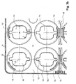
- FIG. 3a Such a tray 8 is shown from the top in an overall view, in FIG. 3b the section at the top left of the illustration according to FIG. 3a , It can now be recognized here how a circumferential elevation contour 18 is arranged on the base surface 11 in each case in the region of each can.
- This elevation contour 18 has a diameter which is substantially greater than the diameter of the lower edge 7 of the can.
- the central area of this elevation serves as a standing area for the lower edge and has for positioning the lower edge 7 each have a pitch circle contour 13 for each can.
- This pitch circle contour is formed as a circle-segment-like bead-shaped elevation, which covers only an angle section of about 30 ° at each can.
- the collision with an optionally present box of a package can be kept as low as possible and still the positioning effect can be ensured.
- six cans in each case in a special way by this pitch circle contours 13 are taken. This is done by, for example, at the somewhat transversely arranged six unit in the upper left corner of FIG. 3a can be detected by each arranged at the corners of beverage cans in each corner forming quadrant of the respective circle by a pitch circle contour 13 'respectively 13'"are taken, and by the two opposite not arranged in the corners doses on the outer side respectively be taken by a pitch circle contour 13 ".
- the actual base 23 is provided for the beverage can, respectively, the lower edge thereof.
- a recess 14 is arranged, which has on two opposite sides on ventilation extensions.
- the pitch circle 13 has over a radius R, this is typically in the range of 51-52 mm.
- the passage openings 14 essentially has a square outer contour with a side length a of approximately 32 mm. At the corners, this square shape is rounded with a radius r of 8 mm. It turns out that this in principle rectangular or square shape has an advantage in terms of a circular or elliptical shape, because the cans can be much better supported on the base 23.
- each passage opening 14 has an extension in the form of a ventilation extension 15. This extends so far that it protrudes further than the circumference of the lower edge 7 of the box, so that, as it were, a passage to the upper-side end surface 4 of an arranged underneath Beverage can is possible and according to a ventilation of this area is possible.
- the ventilation extension has a width of about 5-7 mm and a depth of about 9-10 mm. Wherever a partial circle contour 13 "is arranged on the side 1, this ventilation extension 15 extends directly up to this partial circle contour 13". It should be noted that in the figures, the extensions 15 do not extend equally far outwards in all cases. This is possible, but it is preferred that all expansions 15 extend far outward, as in eg FIG. 3a in the recess 14 of the second-highest row is the case.
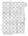
- FIG. 4a is an entire tray 8 shown from the bottom, and in FIG. 4b again a section at the top left in FIG. 4a in detail.
- the passage opening 14 defines the underside 24 of the base 23.
- the upper edge 2 each to be a beverage can. So that this upper edge 2 is trapped, there is a circumferential recessed contour 20 on the underside.
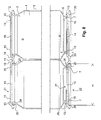
- FIG. 7 is the section along the line AA according to FIG. 4a shown, in a) the entire section is shown and in b only the section on the left side for a beverage can at the top and a bottom.
- the circumferential recess contour 20 by a Offset of this base is formed upwards, wherein on the top of the above-discussed circumferential elevation contour is formed.
- the passage opening 14 has ventilation enlargement in FIG. 15 on both sides.
- FIG. 8 a situation of beverage cans 1 is shown, which is covered on the top by an upper tray and stands on the bottom of a lower tray. A stacking can be easily reproduced by appropriate duplication in the vertical direction. Based on this figure can be seen how the upper edge 2 comes to rest on the bottom 24 and is trapped by the circumferential recess contour 20. Furthermore, it can be seen that the upper edge 2, which has the indicated diameter D, is circumferentially completely supported by the underside 24, that is to say the ventilation extensions 15 do not extend far enough outwards to run for the upper edge 2.
- FIG. 9a a bottom view is shown on a tray ordered with cans, and here it can be seen how the lower edge 7 is not supported in the area of the ventilation extensions 15 and correspondingly each of said ventilation gap 15 is exposed.
- FIG. 9b is a top view on the top tray FIG. 8 and it can be seen here that the upper edge 2 of the cans is not visible through either the through-hole 14 or the ventilation extensions 15 (the visible lines are the lower portion of the cans). It can therefore be recognized how the entire upper edge 2 is circumferentially supported.
Landscapes
- Engineering & Computer Science (AREA)
- Mechanical Engineering (AREA)
- Packages (AREA)
- Stackable Containers (AREA)
Claims (14)
- Dispositif destiné au transport d'une pluralité de cannettes (1), notamment de cannettes de boisson comme des cannettes de boisson en aluminium et/ou de plusieurs unités de manipulation rassemblées en emballages de plusieurs cannettes, par exemple en un multipack, étroitement maintenues entre elles à l'aide d'un élément contenant, notamment au moyen d'un film et/ou d'un emballage en carton, avec une forme de base carrée ou rectangulaire ;
les cannettes (1) pour lesquelles le dispositif est conçu comportant un bord périphérique supérieur (2) ainsi qu'un bord périphérique inférieur (7) et le bord supérieur (2) présentant un diamètre supérieur ou inférieur au bord périphérique inférieur (7) ;
composé d'un plateau (8), le plateau (8) comportant un côté supérieur (21) et un côté inférieur (22) ;
le côté supérieur (21) du plateau (8) comportant pour chaque cannette (1) placée sur une surface d'appui (23) un contour de maintien (13) pour le bord inférieur (7) de la cannette (1), ledit contour de maintien (13) comportant sur le côté intérieur un rayon (R) correspondant pour l'essentiel au rayon extérieur (d/2) du bord inférieur (7) de la cannette (1) ou non essentiellement plus grand et ceignant au moins en partie le bord inférieur (7) ;
et le côté inférieur (22) du plateau (8) prévu pour chaque cannette (1) ceignant de façon périphérique le bord supérieur (2) avec le côté inférieur (24) de la surface d'appui (23) et un contour renfoncé périphérique (20) étant disposé sur ce côté inférieur (24) de la surface d'appui (23), ledit rayon présentant un rayon (m/2) correspondant pour l'essentiel au rayon extérieur (D/2) du bord supérieur (2) ou étant non essentiellement plus grand et ceignant de façon périphérique le bord supérieur (2) ;
caractérisé en ce que :la surface d'appui (23) comporte au moins une ouverture traversante (14) et que l'ouverture traversante (14) comporte au moins un élargissement d'aération (15) et comporte un contour extérieur réalisé de telle sorte que pour chaque position possible d'une cannette (1) positionnée au-dessus du plateau (8), dans cette région, avec son bord inférieur (7) passé à travers le contour de maintien (13), l'ouverture traversante (14) peut être amenée à être couverte par le bord inférieur (2) uniquement dans la région de l'élargissement d'aération (15). - Dispositif selon la revendication 1, caractérisé en ce que le contour de maintien (13) est respectivement réalisé sur le côté supérieur (21) pour chaque cannette (1), uniquement au-dessus d'une section circulaire, cette section circulaire recouvrant tout au plus 120°, de façon préférée tout au plus 90°, notamment de façon préférée tout au plus 45°, de façon tout particulièrement préférée tout au plus 30°.
- Dispositif selon la revendication 2, caractérisé en ce que respectivement pour six cannettes (1) d'un pack de six, disposées en deux rangées de respectivement trois cannettes placées côte à côte, les contours de maintien (13) sont disposés au niveau des quarts de cercle formant dans les coins les cannettes disposées au niveau des coins et sont disposés en côté par rapport au pack de six pour les cannettes (1) non disposées au niveau des coins ;
et/ou que respectivement pour douze cannettes (1) d'un pack de douze, disposées en trois rangées de respectivement quatre cannettes disposées côte à côte, les contours de maintien (13) sont placés au niveau des quarts de cercle formant dans les coins les cannettes disposées au niveau des coins et sont disposés en côté par rapport au pack de douze pour les cannettes (1) non disposées au niveau des coins ;
et/ou que respectivement pour 24 cannettes (1) d'un pack de vingt-quatre, disposées en quatre rangées de respectivement six cannettes disposées côte à côte, les contours de maintien (13) sont placés au niveau des quarts de cercle formant dans les coins les cannettes disposées au niveau des coins et sont disposés en côté par rapport au pack de vingt-quatre pour les cannettes (1) non disposées au niveau des coins. - Dispositif selon l'une quelconque des revendications précédentes, caractérisé en ce que la surface d'appui (23) comporte au moins une ouverture traversante (14) dans la région centrale.
- Dispositif selon l'une quelconque des revendications précédentes, caractérisé en ce que l'ouverture traversante (14) comporte un contour extérieur réalisé de telle sorte qu'en l'absence de position possible d'une cannette (1) retenue en dessous du plateau (8) dans cette région avec son bord supérieur (2) placé dans le contour renfoncé périphérique (20), l'ouverture traversante (14) peut être recouverte par le bord supérieur (2).
- Dispositif selon l'une quelconque des revendications précédentes, caractérisé en ce que l'ouverture traversante (14) présente pour l'essentiel une forme rectangulaire ou carrée, de façon préférée avec des coins arrondis, et qu'en présence d'un élargissement d'aération (15), celui-ci est réalisé sous la forme d'au moins un, de façon préférée d'au moins deux, élargissements rectangulaires disposés en vis-à-vis d'un des côtés.
- Dispositif selon la revendication 6, caractérisé en ce que l'ouverture traversante (14) présente une forme carrée, orientée centralement par rapport au contour de maintien (13) avec une longueur latérale (a) dans la plage de 25-35 mm, les coins étant arrondis, de préférence avec un rayon (r) dans la plage de 5-10 mm et qu'un élargissement d'aération de largeur (b) dans la plage de 3-10 mm et d'une profondeur (t) dans la plage de 5-15 mm se situe respectivement centralement sur les deux côtés de cette forme carrée.
- Dispositif selon l'une quelconque des revendications précédentes, caractérisé en ce que le bord supérieur (2) de la cannette (1) pour laquelle le dispositif est conçu présente un diamètre (D) dans la plage de 53-55 mm, que le bord inférieur (7) de la cannette (1) présente un diamètre (d) dans la plage de 49-52 mm, que les contours de maintien (13) présentent un rayon (R) dans la plage de 50-53 mm et que le contour renfoncé périphérique (20) présente un diamètre (m) dans la plage de 55-56 mm.
- Dispositif selon l'une quelconque des revendications précédentes, caractérisé en ce que le plateau (8) est pour l'essentiel exclusivement en matière plastique, notamment de façon préférée en polyéthylène, polypropylène, polyamide ou un mélange de ces matières, le cas échéant renforcé en fibres.
- Dispositif selon l'une quelconque des revendications précédentes, caractérisé en ce que la surface d'appui (23) présente une épaisseur dans la plage de 1,5-3 mm, notamment de façon préférée dans la plage d'approximativement 2 mm.
- Dispositif selon l'une quelconque des revendications précédentes, caractérisé en ce que le plateau (8) comporte au niveau de son bord périphérique des élargissements de bord notamment orientés respectivement en alternance vers le haut (9) et vers le bas (10) disposés de préférence de telle sorte que les plateaux non chargés en cannettes (1) peuvent directement être empilés les uns sur les autres en engrenant les uns dans les autres à la façon de dents les élargissements de bord orientés vers le haut (9) et vers le bas (10).
- Dispositif selon l'une quelconque des revendications précédentes, caractérisé en ce qu'un plateau (8) est conçu pour transporter 54 cannettes disposées en six rangées de respectivement neuf cannettes disposées côte à côte, les cannettes (1) reposant les unes sur les autres dans les différents plans.
- Dispositif selon l'une quelconque des revendications précédentes, caractérisé en ce qu'il est conçu pour le transport de cannettes de boisson, notamment pour le transport de cannettes de boisson en aluminium standard, le bord supérieur (2) de la cannette de boisson (1) présentant un diamètre (D) dans la plage de 53-55 mm, le bord inférieur (7) de la cannette (1) présentant un diamètre (d) dans la plage de 49-52 mm, les contours de maintien (13) présentant un rayon (R) dans la plage de 50-53 mm et le contour renfoncé périphérique (20) présentant un diamètre (m) dans la plage de 55-56 mm.
- Utilisation d'un dispositif selon l'une quelconque des revendications précédentes destiné au transport de cannettes (1) notamment de façon préférée de cannettes de boisson (1), de façon davantage préférée en disposant les unes au-dessus des autres une pluralité de couches de respectivement une pluralité de rangées disposées côte à côte de cannettes (1) et un dispositif selon l'une quelconque des revendications étant inséré entre chacune des couches ou entre chaque deuxième ou entre chaque troisième couche.
Priority Applications (1)
| Application Number | Priority Date | Filing Date | Title |
|---|---|---|---|
| EP09812705.3A EP2334573B1 (fr) | 2008-09-12 | 2009-09-08 | Dispositif destiné au transport de cannettes de boisson |
Applications Claiming Priority (4)
| Application Number | Priority Date | Filing Date | Title |
|---|---|---|---|
| EP08164222 | 2008-09-12 | ||
| EP08405247 | 2008-10-02 | ||
| EP09812705.3A EP2334573B1 (fr) | 2008-09-12 | 2009-09-08 | Dispositif destiné au transport de cannettes de boisson |
| PCT/EP2009/061628 WO2010029071A1 (fr) | 2008-09-12 | 2009-09-08 | Dispositif de transport de canettes de boissons |
Publications (2)
| Publication Number | Publication Date |
|---|---|
| EP2334573A1 EP2334573A1 (fr) | 2011-06-22 |
| EP2334573B1 true EP2334573B1 (fr) | 2015-02-18 |
Family
ID=41112497
Family Applications (1)
| Application Number | Title | Priority Date | Filing Date |
|---|---|---|---|
| EP09812705.3A Not-in-force EP2334573B1 (fr) | 2008-09-12 | 2009-09-08 | Dispositif destiné au transport de cannettes de boisson |
Country Status (3)
| Country | Link |
|---|---|
| EP (1) | EP2334573B1 (fr) |
| DK (1) | DK2334573T3 (fr) |
| WO (1) | WO2010029071A1 (fr) |
Families Citing this family (2)
| Publication number | Priority date | Publication date | Assignee | Title |
|---|---|---|---|---|
| DE102013207060B4 (de) * | 2013-02-19 | 2015-10-22 | Papacks Ag | Tablett zur Aufnahme und Verpackung von gleichförmigen Behältern |
| FR3028250B1 (fr) * | 2014-11-12 | 2017-09-15 | Lionel Guiguet | Dispositif pour realiser du mobilier en utilisant des boites metalliques de type canettes comme elements porteurs |
Family Cites Families (3)
| Publication number | Priority date | Publication date | Assignee | Title |
|---|---|---|---|---|
| AT1246U1 (de) * | 1995-11-28 | 1997-01-27 | Steco Allibert Europ Plastic L | Tragplatte für getränkedosen |
| US7404486B2 (en) | 2003-12-29 | 2008-07-29 | Matthew Charles Smithers | Modular beverage can interlocking device |
| US20090108002A1 (en) * | 2005-06-22 | 2009-04-30 | Klaus Delbrouck | Arrangement for Transporting Bottles, Drinks Containers and/or Multipacks |
-
2009
- 2009-09-08 DK DK09812705.3T patent/DK2334573T3/en active
- 2009-09-08 EP EP09812705.3A patent/EP2334573B1/fr not_active Not-in-force
- 2009-09-08 WO PCT/EP2009/061628 patent/WO2010029071A1/fr not_active Ceased
Also Published As
| Publication number | Publication date |
|---|---|
| DK2334573T3 (en) | 2015-05-18 |
| WO2010029071A1 (fr) | 2010-03-18 |
| EP2334573A1 (fr) | 2011-06-22 |
Similar Documents
| Publication | Publication Date | Title |
|---|---|---|
| DE3121243C2 (fr) | ||
| EP2055648B1 (fr) | Section destinée à la fabrication d'un emballage circonférentiel pour bouteilles et unité d'emballage en étant pourvue | |
| DE202010013583U1 (de) | Transporteinheit für Großflaschen | |
| EP2530024B1 (fr) | Support de chargement | |
| EP2334573B1 (fr) | Dispositif destiné au transport de cannettes de boisson | |
| DE2357979A1 (de) | Flaschenverpackung | |
| DE29602301U1 (de) | Verpackungsanordnung | |
| EP2383189B1 (fr) | Unité de transport/présentation avec support de transport/présentation pour récipients, de préférence récipients à boissons | |
| WO2011054700A1 (fr) | Dispositif de transport pour récipients, notamment pour bouteilles | |
| DE20080289U1 (de) | Transportplatte für Flaschen und eine damit zu verwendende Flaschenverpackung | |
| DE69524723T2 (de) | Behälter mit laschen zum festklemmen von gegenständen | |
| AT403793B (de) | Stapelbares gebinde aus kunststoff zur aufnahme von konischen kunststoffbechern, insbesondere joghurtbechern | |
| EP1702853B1 (fr) | Support empilable de charge | |
| DE202011102375U1 (de) | Flasche, insbesondere für Getränke, und Kombination einer derartigen Flasche mit einem Transport / Präsentier-Träger | |
| DE4338041C1 (de) | Tray für die Errichtung einer Verpackung zur Aufnahme von Waren | |
| DE29602214U1 (de) | Stapelbare Verpackung, insbesondere in Form einer Falthülle, Faltkiste, Faltschachtel o.dgl. | |
| EP2436612A1 (fr) | Porte-bouteilles | |
| DE202007006183U1 (de) | Vorrichtung zum Transport von Flaschen und/oder Gebinden | |
| DE19525065C2 (de) | Kasten, insbesondere in Kreuzverbundstapelung | |
| AT372920B (de) | Stapelbarer transportbehaelter | |
| AT501749B1 (de) | Getränkebehältertablar | |
| DE69908490T2 (de) | System zum Lagern von Gruppen gefüllter, übereinandergestapelter, mit einem Flansch versehener Behälter in einer aus halbsteifem Material hergestellten Schale | |
| DE29922359U1 (de) | Zuschnitt aus Wellpappe für stapelbares polygonales Behältnis, aus solchem Zuschnitt hergestelltes Behältnis sowie Behältnissatz, umfassend mehrerer solcher Behältnisse | |
| EP3009367B1 (fr) | Support de chargement | |
| DE3441383C2 (fr) |
Legal Events
| Date | Code | Title | Description |
|---|---|---|---|
| PUAI | Public reference made under article 153(3) epc to a published international application that has entered the european phase |
Free format text: ORIGINAL CODE: 0009012 |
|
| 17P | Request for examination filed |
Effective date: 20110406 |
|
| AK | Designated contracting states |
Kind code of ref document: A1 Designated state(s): AT BE BG CH CY CZ DE DK EE ES FI FR GB GR HR HU IE IS IT LI LT LU LV MC MK MT NL NO PL PT RO SE SI SK SM TR |
|
| AX | Request for extension of the european patent |
Extension state: AL BA RS |
|
| 19U | Interruption of proceedings before grant |
Effective date: 20110808 |
|
| 19U | Interruption of proceedings before grant |
Effective date: 20110805 |
|
| 19W | Proceedings resumed before grant after interruption of proceedings |
Effective date: 20121203 |
|
| RAP1 | Party data changed (applicant data changed or rights of an application transferred) |
Owner name: DELBROUCK, MARKUS KLAUS Owner name: DELBROUCK, ANDREA URSULA Owner name: DELBROUCK, INES MARIA |
|
| RIN1 | Information on inventor provided before grant (corrected) |
Inventor name: DELBROUCK, INES MARIA Inventor name: DELBROUCK, MARKUS KLAUS Inventor name: DELBROUCK, ANDREA URSULA |
|
| RIN1 | Information on inventor provided before grant (corrected) |
Inventor name: DELBROUCK, MARKUS KLAUS |
|
| GRAP | Despatch of communication of intention to grant a patent |
Free format text: ORIGINAL CODE: EPIDOSNIGR1 |
|
| INTG | Intention to grant announced |
Effective date: 20140910 |
|
| RIN1 | Information on inventor provided before grant (corrected) |
Inventor name: DELBROUCK, KLAUS |
|
| DAX | Request for extension of the european patent (deleted) | ||
| GRAS | Grant fee paid |
Free format text: ORIGINAL CODE: EPIDOSNIGR3 |
|
| GRAA | (expected) grant |
Free format text: ORIGINAL CODE: 0009210 |
|
| AK | Designated contracting states |
Kind code of ref document: B1 Designated state(s): AT BE BG CH CY CZ DE DK EE ES FI FR GB GR HR HU IE IS IT LI LT LU LV MC MK MT NL NO PL PT RO SE SI SK SM TR |
|
| REG | Reference to a national code |
Ref country code: GB Ref legal event code: FG4D Free format text: NOT ENGLISH |
|
| REG | Reference to a national code |
Ref country code: CH Ref legal event code: EP |
|
| REG | Reference to a national code |
Ref country code: AT Ref legal event code: REF Ref document number: 710570 Country of ref document: AT Kind code of ref document: T Effective date: 20150315 |
|
| REG | Reference to a national code |
Ref country code: IE Ref legal event code: FG4D Free format text: LANGUAGE OF EP DOCUMENT: GERMAN |
|
| REG | Reference to a national code |
Ref country code: DE Ref legal event code: R096 Ref document number: 502009010629 Country of ref document: DE Effective date: 20150402 |
|
| REG | Reference to a national code |
Ref country code: DK Ref legal event code: T3 Effective date: 20150512 |
|
| REG | Reference to a national code |
Ref country code: SE Ref legal event code: TRGR |
|
| REG | Reference to a national code |
Ref country code: NL Ref legal event code: VDEP Effective date: 20150218 |
|
| REG | Reference to a national code |
Ref country code: LT Ref legal event code: MG4D |
|
| PG25 | Lapsed in a contracting state [announced via postgrant information from national office to epo] |
Ref country code: LT Free format text: LAPSE BECAUSE OF FAILURE TO SUBMIT A TRANSLATION OF THE DESCRIPTION OR TO PAY THE FEE WITHIN THE PRESCRIBED TIME-LIMIT Effective date: 20150218 Ref country code: NO Free format text: LAPSE BECAUSE OF FAILURE TO SUBMIT A TRANSLATION OF THE DESCRIPTION OR TO PAY THE FEE WITHIN THE PRESCRIBED TIME-LIMIT Effective date: 20150518 Ref country code: FI Free format text: LAPSE BECAUSE OF FAILURE TO SUBMIT A TRANSLATION OF THE DESCRIPTION OR TO PAY THE FEE WITHIN THE PRESCRIBED TIME-LIMIT Effective date: 20150218 Ref country code: HR Free format text: LAPSE BECAUSE OF FAILURE TO SUBMIT A TRANSLATION OF THE DESCRIPTION OR TO PAY THE FEE WITHIN THE PRESCRIBED TIME-LIMIT Effective date: 20150218 Ref country code: ES Free format text: LAPSE BECAUSE OF FAILURE TO SUBMIT A TRANSLATION OF THE DESCRIPTION OR TO PAY THE FEE WITHIN THE PRESCRIBED TIME-LIMIT Effective date: 20150218 |
|
| PG25 | Lapsed in a contracting state [announced via postgrant information from national office to epo] |
Ref country code: NL Free format text: LAPSE BECAUSE OF FAILURE TO SUBMIT A TRANSLATION OF THE DESCRIPTION OR TO PAY THE FEE WITHIN THE PRESCRIBED TIME-LIMIT Effective date: 20150218 Ref country code: GR Free format text: LAPSE BECAUSE OF FAILURE TO SUBMIT A TRANSLATION OF THE DESCRIPTION OR TO PAY THE FEE WITHIN THE PRESCRIBED TIME-LIMIT Effective date: 20150519 Ref country code: LV Free format text: LAPSE BECAUSE OF FAILURE TO SUBMIT A TRANSLATION OF THE DESCRIPTION OR TO PAY THE FEE WITHIN THE PRESCRIBED TIME-LIMIT Effective date: 20150218 Ref country code: IS Free format text: LAPSE BECAUSE OF FAILURE TO SUBMIT A TRANSLATION OF THE DESCRIPTION OR TO PAY THE FEE WITHIN THE PRESCRIBED TIME-LIMIT Effective date: 20150618 |
|
| PG25 | Lapsed in a contracting state [announced via postgrant information from national office to epo] |
Ref country code: SK Free format text: LAPSE BECAUSE OF FAILURE TO SUBMIT A TRANSLATION OF THE DESCRIPTION OR TO PAY THE FEE WITHIN THE PRESCRIBED TIME-LIMIT Effective date: 20150218 Ref country code: EE Free format text: LAPSE BECAUSE OF FAILURE TO SUBMIT A TRANSLATION OF THE DESCRIPTION OR TO PAY THE FEE WITHIN THE PRESCRIBED TIME-LIMIT Effective date: 20150218 Ref country code: CZ Free format text: LAPSE BECAUSE OF FAILURE TO SUBMIT A TRANSLATION OF THE DESCRIPTION OR TO PAY THE FEE WITHIN THE PRESCRIBED TIME-LIMIT Effective date: 20150218 Ref country code: RO Free format text: LAPSE BECAUSE OF FAILURE TO SUBMIT A TRANSLATION OF THE DESCRIPTION OR TO PAY THE FEE WITHIN THE PRESCRIBED TIME-LIMIT Effective date: 20150218 |
|
| REG | Reference to a national code |
Ref country code: DE Ref legal event code: R097 Ref document number: 502009010629 Country of ref document: DE |
|
| PG25 | Lapsed in a contracting state [announced via postgrant information from national office to epo] |
Ref country code: PL Free format text: LAPSE BECAUSE OF FAILURE TO SUBMIT A TRANSLATION OF THE DESCRIPTION OR TO PAY THE FEE WITHIN THE PRESCRIBED TIME-LIMIT Effective date: 20150218 |
|
| PLBE | No opposition filed within time limit |
Free format text: ORIGINAL CODE: 0009261 |
|
| STAA | Information on the status of an ep patent application or granted ep patent |
Free format text: STATUS: NO OPPOSITION FILED WITHIN TIME LIMIT |
|
| PG25 | Lapsed in a contracting state [announced via postgrant information from national office to epo] |
Ref country code: IT Free format text: LAPSE BECAUSE OF FAILURE TO SUBMIT A TRANSLATION OF THE DESCRIPTION OR TO PAY THE FEE WITHIN THE PRESCRIBED TIME-LIMIT Effective date: 20150218 |
|
| 26N | No opposition filed |
Effective date: 20151119 |
|
| PG25 | Lapsed in a contracting state [announced via postgrant information from national office to epo] |
Ref country code: SI Free format text: LAPSE BECAUSE OF FAILURE TO SUBMIT A TRANSLATION OF THE DESCRIPTION OR TO PAY THE FEE WITHIN THE PRESCRIBED TIME-LIMIT Effective date: 20150218 |
|
| PG25 | Lapsed in a contracting state [announced via postgrant information from national office to epo] |
Ref country code: LU Free format text: LAPSE BECAUSE OF FAILURE TO SUBMIT A TRANSLATION OF THE DESCRIPTION OR TO PAY THE FEE WITHIN THE PRESCRIBED TIME-LIMIT Effective date: 20150908 Ref country code: MC Free format text: LAPSE BECAUSE OF FAILURE TO SUBMIT A TRANSLATION OF THE DESCRIPTION OR TO PAY THE FEE WITHIN THE PRESCRIBED TIME-LIMIT Effective date: 20150218 |
|
| REG | Reference to a national code |
Ref country code: CH Ref legal event code: PL |
|
| REG | Reference to a national code |
Ref country code: IE Ref legal event code: MM4A |
|
| REG | Reference to a national code |
Ref country code: FR Ref legal event code: ST Effective date: 20160531 |
|
| PG25 | Lapsed in a contracting state [announced via postgrant information from national office to epo] |
Ref country code: LI Free format text: LAPSE BECAUSE OF NON-PAYMENT OF DUE FEES Effective date: 20150930 Ref country code: IE Free format text: LAPSE BECAUSE OF NON-PAYMENT OF DUE FEES Effective date: 20150908 Ref country code: CH Free format text: LAPSE BECAUSE OF NON-PAYMENT OF DUE FEES Effective date: 20150930 |
|
| PG25 | Lapsed in a contracting state [announced via postgrant information from national office to epo] |
Ref country code: FR Free format text: LAPSE BECAUSE OF NON-PAYMENT OF DUE FEES Effective date: 20150930 |
|
| REG | Reference to a national code |
Ref country code: AT Ref legal event code: MM01 Ref document number: 710570 Country of ref document: AT Kind code of ref document: T Effective date: 20150908 |
|
| PG25 | Lapsed in a contracting state [announced via postgrant information from national office to epo] |
Ref country code: AT Free format text: LAPSE BECAUSE OF NON-PAYMENT OF DUE FEES Effective date: 20150908 |
|
| PG25 | Lapsed in a contracting state [announced via postgrant information from national office to epo] |
Ref country code: MT Free format text: LAPSE BECAUSE OF FAILURE TO SUBMIT A TRANSLATION OF THE DESCRIPTION OR TO PAY THE FEE WITHIN THE PRESCRIBED TIME-LIMIT Effective date: 20150218 |
|
| PG25 | Lapsed in a contracting state [announced via postgrant information from national office to epo] |
Ref country code: BG Free format text: LAPSE BECAUSE OF FAILURE TO SUBMIT A TRANSLATION OF THE DESCRIPTION OR TO PAY THE FEE WITHIN THE PRESCRIBED TIME-LIMIT Effective date: 20150218 Ref country code: SM Free format text: LAPSE BECAUSE OF FAILURE TO SUBMIT A TRANSLATION OF THE DESCRIPTION OR TO PAY THE FEE WITHIN THE PRESCRIBED TIME-LIMIT Effective date: 20150218 Ref country code: HU Free format text: LAPSE BECAUSE OF FAILURE TO SUBMIT A TRANSLATION OF THE DESCRIPTION OR TO PAY THE FEE WITHIN THE PRESCRIBED TIME-LIMIT; INVALID AB INITIO Effective date: 20090908 |
|
| PG25 | Lapsed in a contracting state [announced via postgrant information from national office to epo] |
Ref country code: CY Free format text: LAPSE BECAUSE OF FAILURE TO SUBMIT A TRANSLATION OF THE DESCRIPTION OR TO PAY THE FEE WITHIN THE PRESCRIBED TIME-LIMIT Effective date: 20150218 |
|
| PG25 | Lapsed in a contracting state [announced via postgrant information from national office to epo] |
Ref country code: BE Free format text: LAPSE BECAUSE OF NON-PAYMENT OF DUE FEES Effective date: 20150930 |
|
| PG25 | Lapsed in a contracting state [announced via postgrant information from national office to epo] |
Ref country code: TR Free format text: LAPSE BECAUSE OF FAILURE TO SUBMIT A TRANSLATION OF THE DESCRIPTION OR TO PAY THE FEE WITHIN THE PRESCRIBED TIME-LIMIT Effective date: 20150218 |
|
| PG25 | Lapsed in a contracting state [announced via postgrant information from national office to epo] |
Ref country code: MK Free format text: LAPSE BECAUSE OF FAILURE TO SUBMIT A TRANSLATION OF THE DESCRIPTION OR TO PAY THE FEE WITHIN THE PRESCRIBED TIME-LIMIT Effective date: 20150218 Ref country code: PT Free format text: LAPSE BECAUSE OF FAILURE TO SUBMIT A TRANSLATION OF THE DESCRIPTION OR TO PAY THE FEE WITHIN THE PRESCRIBED TIME-LIMIT Effective date: 20150218 |
|
| PGFP | Annual fee paid to national office [announced via postgrant information from national office to epo] |
Ref country code: DK Payment date: 20190920 Year of fee payment: 11 Ref country code: SE Payment date: 20190918 Year of fee payment: 11 Ref country code: DE Payment date: 20190918 Year of fee payment: 11 |
|
| PGFP | Annual fee paid to national office [announced via postgrant information from national office to epo] |
Ref country code: GB Payment date: 20190925 Year of fee payment: 11 |
|
| REG | Reference to a national code |
Ref country code: DE Ref legal event code: R119 Ref document number: 502009010629 Country of ref document: DE |
|
| REG | Reference to a national code |
Ref country code: DK Ref legal event code: EBP Effective date: 20200930 |
|
| GBPC | Gb: european patent ceased through non-payment of renewal fee |
Effective date: 20200908 |
|
| PG25 | Lapsed in a contracting state [announced via postgrant information from national office to epo] |
Ref country code: DE Free format text: LAPSE BECAUSE OF NON-PAYMENT OF DUE FEES Effective date: 20210401 |
|
| PG25 | Lapsed in a contracting state [announced via postgrant information from national office to epo] |
Ref country code: SE Free format text: LAPSE BECAUSE OF NON-PAYMENT OF DUE FEES Effective date: 20200909 Ref country code: GB Free format text: LAPSE BECAUSE OF NON-PAYMENT OF DUE FEES Effective date: 20200908 |
|
| REG | Reference to a national code |
Ref country code: SE Ref legal event code: EUG |
|
| PG25 | Lapsed in a contracting state [announced via postgrant information from national office to epo] |
Ref country code: DK Free format text: LAPSE BECAUSE OF NON-PAYMENT OF DUE FEES Effective date: 20200930 |