EP2334897B1 - Improved control system - Google Patents
Improved control system Download PDFInfo
- Publication number
- EP2334897B1 EP2334897B1 EP09785714.8A EP09785714A EP2334897B1 EP 2334897 B1 EP2334897 B1 EP 2334897B1 EP 09785714 A EP09785714 A EP 09785714A EP 2334897 B1 EP2334897 B1 EP 2334897B1
- Authority
- EP
- European Patent Office
- Prior art keywords
- power generation
- generation device
- control system
- hydraulic pressure
- subterranean well
- Prior art date
- Legal status (The legal status is an assumption and is not a legal conclusion. Google has not performed a legal analysis and makes no representation as to the accuracy of the status listed.)
- Not-in-force
Links
- 238000010248 power generation Methods 0.000 claims description 55
- 239000012530 fluid Substances 0.000 claims description 12
- 238000000034 method Methods 0.000 claims description 5
- 230000006835 compression Effects 0.000 claims description 4
- 238000007906 compression Methods 0.000 claims description 4
- 238000004146 energy storage Methods 0.000 claims description 3
- 230000005484 gravity Effects 0.000 claims description 3
- 239000003990 capacitor Substances 0.000 claims description 2
- 229930195733 hydrocarbon Natural products 0.000 description 9
- 150000002430 hydrocarbons Chemical class 0.000 description 9
- 238000004519 manufacturing process Methods 0.000 description 7
- 239000004215 Carbon black (E152) Substances 0.000 description 1
- 230000003213 activating effect Effects 0.000 description 1
- 230000001419 dependent effect Effects 0.000 description 1
- 238000005553 drilling Methods 0.000 description 1
- 238000000605 extraction Methods 0.000 description 1
- 238000002347 injection Methods 0.000 description 1
- 239000007924 injection Substances 0.000 description 1
- 238000012986 modification Methods 0.000 description 1
- 230000004048 modification Effects 0.000 description 1
- 239000002245 particle Substances 0.000 description 1
- 239000000126 substance Substances 0.000 description 1
Images




Classifications
-
- E—FIXED CONSTRUCTIONS
- E21—EARTH OR ROCK DRILLING; MINING
- E21B—EARTH OR ROCK DRILLING; OBTAINING OIL, GAS, WATER, SOLUBLE OR MELTABLE MATERIALS OR A SLURRY OF MINERALS FROM WELLS
- E21B41/00—Equipment or details not covered by groups E21B15/00 - E21B40/00
- E21B41/0085—Adaptations of electric power generating means for use in boreholes
Definitions
- the present invention relates to an improved control system in a subterranean well. Particularly, but not exclusively the present invention relates to improved control system for controlling a plurality of tools, equipment and apparatus which are positioned in a subterranean well.
- Directional drilling has made the extraction of hydrocarbons from small reservoirs economically viable because the borehole can be directed in three dimensions through a number of pockets of hydrocarbons.
- the hydrocarbons contained in each of these reservoirs flows through a production tube to the surface.
- Balanced fluid or optimised flow regimes are designed to intend to get the flow from the reservoirs to the surface as quickly as possible and maximise the amount of hydrocarbons extracted from each reservoir. These flow regimes may dictate that the different reservoirs be emptied at different times.
- the flow of hydrocarbons from a reservoir into the production tube is controlled using downhole tools such as valves.
- US2003/0116969 discloses use of annulus pressure to generate power downhole.
- US2008/0128123 discloses a downhole micro generator attached to a downhole tool, the micro generator being powered by a motive gas source.
- US2007/0194948 , GB2435310 and US2005/0012340 all disclose electrical generators powered by the flow of well fluids.
- US2005039921 relates to downhole operations that produce electrical power within a wellbore and, in particular, to a system for generating power from fluid flow through production tubing in a wellbore that imparts rotation to a magnetized rotation member that generates a magnetic field to produce usable power.
- Downhole valves are, generally speaking, hydraulically controlled. Hydraulic systems are used to control the operation of tools positioned in the well and can comprise surface equipment such as a hydraulic tank, pump etc and control lines for connecting the surface equipment to the downhole tools. The control lines can be connected to one or more downhole tools.
- each tool that is to be controlled will have two dedicated hydraulic lines.
- the "open" line extends from the surface equipment to the tool and is used for transporting hydraulic fluid to the downhole control valve to operated the tool, while the “close” line extends from the tool to the surface equipment and provides a path for returning hydraulic fluid to the surface.
- the practical limit to the number of tools that can be controlled using the direct hydraulic arrangement is three, that is six separate hydraulic lines, due to the physical restraints in positioning hydraulic lines in a well.
- the tubing hanger through which the hydraulic lines run also has to accommodate lines for a gauge system, at least one safety valve and often a chemical injection line, which limits the number of hydraulic lines the hanger can accommodate.
- a common close arrangement can be employed in which an open line is run to each tool to be controlled and a common close line is connected to each tool to return hydraulic fluid to the surface.
- the common close system has a practical limit of controlling five tools through the six separate hydraulic lines.
- a single hydraulic line is dedicated to each tool and is connected to each tool via a separate, dedicated controller for each tool.
- the hydraulic fluid in the dedicated line is pressurised to a first level.
- the hydraulic fluid in the dedicated line is pressurised to a higher level so as to close the tool.
- a digital hydraulics system two hydraulic lines are run from the surface equipment to a downhole controller that is connected to each of the tools to be controlled. Each controller is programmed to operate upon receiving a distinct sequence of pressure pulses received through these two hydraulic lines. Each tool has another hydraulic line is connected thereto as a common return for hydraulic fluid to the surface.
- the controllers employed in the single line and the digital hydraulics arrangements are complex devices incorporating numerous elastomeric seals and springs, which are subject to failure.
- these controllers used small, inline filters to remove particles from the hydraulic fluid that might otherwise contaminate the controllers. These filters are prone to clogging and collapsing.
- the complex nature of the pressure sequences requires a computer operated pump and valve manifold, which is expensive.
- RFID tags are programmed with a message for a specific downhole tool.
- the tag is sent down a control line which runs adjacent the tools.
- the control line includes a tag reader for each downhole tool, each reader reading the message on the tag as it passes.
- the instruction may be to open a valve to allow hydrocarbons to flow into the production tube.
- the drawback of such a system is the requirement for power to be continuously supplied to the readers to detect the presence of a tag and then to provide power to the control system to actuate the specific tool.
- the power is generally provided by batteries. As these batteries are continually supplying power the downhole readers, they can be drained over a period of 2 to 3 weeks and require replacement which can be an extremely expensive and time consuming process.
- a control system for use in a subterranean well for controlling at least one downhole tool comprising:
- Each power generation device may be adapted to supply electrical power to more than one downhole apparatus.
- a power generation device may power an RFID tag reader and a downhole apparatus such as a valve.
- Each power generation device may be adapted to supply electrical power to an energy storage device such as a battery, a capacitor, a spring, a compressed fluid device such as a gas spring or the like.
- an energy storage device such as a battery, a capacitor, a spring, a compressed fluid device such as a gas spring or the like.
- each power generation device may be adapted to supply electrical power to a drive means to raise a weight against gravity. Energy would be stored in such a device, which can be harnessed by allowing the weight to fall under the influence of gravity.
- each power generation device converts the applied hydraulic pressure in to linear motion.
- each power generation device comprises a piston to convert the applied hydraulic pressure in to linear motion.
- each power generation device is further adapted to convert the linear motion into rotary motion.
- Each power generation device may include a ball screw or rack and pinion for this purpose.
- each power generation device is adapted to convert the applied hydraulic pressure into rotary motion.
- each power generation device is adapted to convert rotary motion to electrical power.
- Each power generation device may include a generator for this purpose.
- the generator may be a dynamo.
- a dynamo can generate AC or DC power.
- control system further comprises a rectifier or switch mode regulator.
- a rectifier or switch mode regulator converts an AC input into a DC output.
- Each power generation device may include a biasing means adapted to resist the application of hydraulic pressure.
- each power generation device converts the applied hydraulic pressure into linear motion using a piston
- the piston is moveable between a first position and a second position and comprises a biasing means to bias the piston to the first position.
- the hydraulic pressure moves the piston against the biasing means to the second position, generating linear motion.
- the biasing means returns the piston to the first position generating further linear motion which is, in turn, converted into electrical power.
- the biasing means may comprise a compression spring, a wind up spring, a coil spring, a leaf spring, a gas spring, well pressure, a suspended weight or the like.
- downhole pressure could be utilised to provide the biasing means or to return the piston to the first position.
- a second control line may be provided in the well to provide the biasing means or to return the piston to the first position.
- a method of controlling at least one downhole tool positioned within a subterranean well comprising the steps of: applying a hydraulic pressure from surface along a control line, the control line extending from surface to more than one power generation device, each power generation device adapted to convert the applied hydraulic pressure into electrical energy to power at least one apparatus positioned within the subterranean well.
- FIG 1 a schematic of a control system, generally indicated by reference numeral 10, according to a first embodiment of the invention.
- the control system 10 controls the flow of hydrocarbons from each of four hydrocarbon reservoirs 12a-d into a production tube 14 which is disposed within a subterranean well 16, the production tube 14 extending from the reservoirs 12a-d up to an oil rig 18. Specifically, the control system 10 controls four downhole tools 20a-d which permit the hydrocarbons from reservoirs 12a-d respectively to flow into the production tube 14.
- control system 10 controls each of the four downhole tools by selectively allowing each tool 20 to be exposed to hydraulic pressure applied through a first hydraulic line 22 and/or a second hydraulic line 24.
- the control system 10 comprises four control system units 26a-d.
- Each control system unit 26 comprises a power generation device 28, the power generation device 28 adapted to supply electrical power to two apparatus; a needle valve 30 and an RFID tag reader 32.
- the control system 10 further comprises a control line 34 which supplies hydraulic pressure from the rig 18 to each of the power generation devices 28.
- the third control line 34 includes a valve 33 which can be closed from surface to allow for hydraulic pressure to be built up in the third control line 34.
- each power generation device 28 is adapted to generate power from the applied hydraulic pressure, the generated power being used to operate the needle valve 30 and/or the RFID tag reader 32.
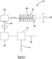
- Each power generation device 28 comprises a piston 40 in a housing 42.
- the piston 40 is shown in Figure 3 located in a first position to which it is biased by a compression spring 44.
- the piston 40 is connected to a ball screw device 46 for converting linear motion of the piston 40 into rotary motion.
- the rotary motion is transferred by a transfer rod 48 to a generator 50.
- the generator 50 is connected to a rectifier 52 which produces a direct current, which is supplied to the needle valve (not shown) by a first wire 54 and to the RFID tag reader (not shown) by a second wire 56.
- the third control line valve 33 is closed and hydraulic pressure is applied through the third control line 34, to the piston 40.
- the application of pressure moves the piston 40 towards the ballscrew 46, against the bias of the compression spring 44 generating electrical power through the generator 50 and rectifier 52 for supply to the needle valve (not shown) and RFID tag reader (not shown).
- the hydraulic pressure in the third control line 34 is released by opening the third control line valve 33, allowing the piston 40 to travel back to the first position. During this return travel more electrical power is generated which the rectifier 52 converts to direct current for supply to the needle valve (not shown) and the RFID tag reader (not shown).
- the objective of the control system 10 is to allow one of the tools 20 to be operated by exposure to hydraulic pressure through one of the first or second control lines 22,24.
- an RFID tag (not shown) is to be sent from the rig 18 with an instruction to operate the third tool 20c.
- the third tool 20c is to be operated by opening the third needle valve 30c permitting a hydraulic pressure applied by the first control line 22 to be released by activating the tool 20c.
- the first step of this operation is to apply a hydraulic pressure to the third control line 34 to generate power, through the power generation devices 28a-d to, initially, operate the RFID tag readers 32a-d, and apply a hydraulic pressure through the first hydraulic line 22 to operate the tool 20c.
- the tool 20c is prevented from operating by the needle valve 30c which is closed and is containing the pressure.
- the pressure in the third control line 34 is reduced by opening the third control line valve 33, permitting the pistons 40 to return to their start positions and generate further power.
- the readers 32a-d are operational and the third control line valve 33 is open, RFID tags containing the message to operate the third tool 20c are sent down the third control line 34.
- the tag flows down the third control line 34 passing through the four tag readers 32a-d.
- the first, second and fourth readers 32a,b,d will ignore the message on the tag but the third reader 32c will transfer the message to the needle valve 30c.
- the needle valve 30c opens, releasing the hydraulic pressure in the first hydraulic line 22 permitting the tool 20c to operate.
- FIG 4 a schematic of a control system 110 according to a second embodiment of the present invention.
- This system 110 is largely similar to the system 10 of the first embodiment, the difference being that each power generation device 128 is operated by the application of hydraulic pressure through the second control line 124. The operation of the system 110 is otherwise the same.
- FIG 5 a schematic of a control system 210 according to a third embodiment of the present invention.
- This system is largely similar to the system 110 of the second embodiment, the difference being that the power generation devices 228 are connected to both the first and second control lines 222,224.
- these lines 222,224 are fed to either side of the piston 240.
- there is no biasing spring in the housing 242 the piston 224 being moved to the left by application of hydraulic pressure through second line 224, and returned to the start position by the application of pressure through the first hydraulic line 222.
- each power generation device may supply power to a battery or other energy storage device for storage until required.
Landscapes
- Life Sciences & Earth Sciences (AREA)
- Engineering & Computer Science (AREA)
- Geology (AREA)
- Mining & Mineral Resources (AREA)
- Physics & Mathematics (AREA)
- Environmental & Geological Engineering (AREA)
- Fluid Mechanics (AREA)
- General Life Sciences & Earth Sciences (AREA)
- Geochemistry & Mineralogy (AREA)
- Other Liquid Machine Or Engine Such As Wave Power Use (AREA)
Applications Claiming Priority (2)
| Application Number | Priority Date | Filing Date | Title |
|---|---|---|---|
| GB0818010A GB0818010D0 (en) | 2008-10-02 | 2008-10-02 | Improved control system |
| PCT/GB2009/051286 WO2010038072A1 (en) | 2008-10-02 | 2009-10-01 | Improved control system |
Publications (2)
| Publication Number | Publication Date |
|---|---|
| EP2334897A1 EP2334897A1 (en) | 2011-06-22 |
| EP2334897B1 true EP2334897B1 (en) | 2019-05-08 |
Family
ID=40019911
Family Applications (1)
| Application Number | Title | Priority Date | Filing Date |
|---|---|---|---|
| EP09785714.8A Not-in-force EP2334897B1 (en) | 2008-10-02 | 2009-10-01 | Improved control system |
Country Status (7)
| Country | Link |
|---|---|
| US (1) | US8950503B2 (da) |
| EP (1) | EP2334897B1 (da) |
| BR (1) | BRPI0920716B1 (da) |
| CA (1) | CA2739529C (da) |
| DK (1) | DK2334897T3 (da) |
| GB (1) | GB0818010D0 (da) |
| WO (1) | WO2010038072A1 (da) |
Families Citing this family (12)
| Publication number | Priority date | Publication date | Assignee | Title |
|---|---|---|---|---|
| GB0425008D0 (en) | 2004-11-12 | 2004-12-15 | Petrowell Ltd | Method and apparatus |
| US10262168B2 (en) | 2007-05-09 | 2019-04-16 | Weatherford Technology Holdings, Llc | Antenna for use in a downhole tubular |
| GB0720421D0 (en) | 2007-10-19 | 2007-11-28 | Petrowell Ltd | Method and apparatus for completing a well |
| GB0804306D0 (en) | 2008-03-07 | 2008-04-16 | Petrowell Ltd | Device |
| GB0818010D0 (en) * | 2008-10-02 | 2008-11-05 | Petrowell Ltd | Improved control system |
| GB0914650D0 (en) | 2009-08-21 | 2009-09-30 | Petrowell Ltd | Apparatus and method |
| GB2496913B (en) | 2011-11-28 | 2018-02-21 | Weatherford Uk Ltd | Torque limiting device |
| EP2917473B1 (en) * | 2013-01-28 | 2019-08-14 | Halliburton Energy Services, Inc. | Downhole control system having a versatile manifold and method for use of same |
| US10024133B2 (en) | 2013-07-26 | 2018-07-17 | Weatherford Technology Holdings, Llc | Electronically-actuated, multi-set straddle borehole treatment apparatus |
| US9644472B2 (en) | 2014-01-21 | 2017-05-09 | Baker Hughes Incorporated | Remote pressure readout while deploying and undeploying coiled tubing and other well tools |
| US10954762B2 (en) | 2016-09-13 | 2021-03-23 | Schlumberger Technology Corporation | Completion assembly |
| NO349490B1 (en) * | 2022-10-20 | 2026-02-02 | Hovem As | Downhole power generator and communication device |
Citations (1)
| Publication number | Priority date | Publication date | Assignee | Title |
|---|---|---|---|---|
| US20050039921A1 (en) * | 2002-01-17 | 2005-02-24 | Schultz Roger L. | Wellbore power generating system for downhole operation |
Family Cites Families (30)
| Publication number | Priority date | Publication date | Assignee | Title |
|---|---|---|---|---|
| GB1462359A (en) * | 1973-08-31 | 1977-01-26 | Russell M K | Power generation in underground drilling operations |
| US4532614A (en) * | 1981-06-01 | 1985-07-30 | Peppers James M | Wall bore electrical generator |
| DE3277825D1 (en) * | 1981-11-24 | 1988-01-21 | Shell Int Research | Means for generating electric energy in a borehole during drilling thereof |
| US4515225A (en) * | 1982-01-29 | 1985-05-07 | Smith International, Inc. | Mud energized electrical generating method and means |
| EP0327432B1 (fr) * | 1988-01-29 | 1997-09-24 | Institut Français du Pétrole | Procédé et dispositif pour commander hydrauliquement et sélectivement, au moins deux outils ou instruments d'un dispositif, vanne permettant la mise en oeuvre de la méthode ou utilisant ledit dispositif |
| US5149984A (en) * | 1991-02-20 | 1992-09-22 | Halliburton Company | Electric power supply for use downhole |
| US5101907A (en) * | 1991-02-20 | 1992-04-07 | Halliburton Company | Differential actuating system for downhole tools |
| US5839508A (en) * | 1995-02-09 | 1998-11-24 | Baker Hughes Incorporated | Downhole apparatus for generating electrical power in a well |
| US5965964A (en) * | 1997-09-16 | 1999-10-12 | Halliburton Energy Services, Inc. | Method and apparatus for a downhole current generator |
| US6679332B2 (en) * | 2000-01-24 | 2004-01-20 | Shell Oil Company | Petroleum well having downhole sensors, communication and power |
| US6717283B2 (en) * | 2001-12-20 | 2004-04-06 | Halliburton Energy Services, Inc. | Annulus pressure operated electric power generator |
| US6988556B2 (en) * | 2002-02-19 | 2006-01-24 | Halliburton Energy Services, Inc. | Deep set safety valve |
| US7055598B2 (en) * | 2002-08-26 | 2006-06-06 | Halliburton Energy Services, Inc. | Fluid flow control device and method for use of same |
| US7002261B2 (en) | 2003-07-15 | 2006-02-21 | Conocophillips Company | Downhole electrical submersible power generator |
| GB2405725B (en) * | 2003-09-05 | 2006-11-01 | Schlumberger Holdings | Borehole telemetry system |
| US7133325B2 (en) * | 2004-03-09 | 2006-11-07 | Schlumberger Technology Corporation | Apparatus and method for generating electrical power in a borehole |
| US7201239B1 (en) * | 2004-05-03 | 2007-04-10 | Aps Technologies, Inc. | Power-generating device for use in drilling operations |
| US8033328B2 (en) * | 2004-11-05 | 2011-10-11 | Schlumberger Technology Corporation | Downhole electric power generator |
| US7190084B2 (en) * | 2004-11-05 | 2007-03-13 | Hall David R | Method and apparatus for generating electrical energy downhole |
| US7699102B2 (en) * | 2004-12-03 | 2010-04-20 | Halliburton Energy Services, Inc. | Rechargeable energy storage device in a downhole operation |
| EP1856789B1 (en) * | 2005-02-08 | 2018-08-15 | Welldynamics, Inc. | Downhole electrical power generator |
| US7504963B2 (en) * | 2005-05-21 | 2009-03-17 | Hall David R | System and method for providing electrical power downhole |
| US7988409B2 (en) | 2006-02-17 | 2011-08-02 | Schlumberger Technology Corporation | Method and apparatus for extending flow range of a downhole turbine |
| US7635029B2 (en) * | 2006-05-11 | 2009-12-22 | Schlumberger Technology Corporation | Downhole electrical-to-hydraulic conversion module for well completions |
| US7834777B2 (en) | 2006-12-01 | 2010-11-16 | Baker Hughes Incorporated | Downhole power source |
| US7823636B2 (en) * | 2007-09-10 | 2010-11-02 | Schlumberger Technology Corporation | Packer |
| AU2008361676B2 (en) * | 2008-09-09 | 2013-03-14 | Welldynamics, Inc. | Remote actuation of downhole well tools |
| CA2735427C (en) * | 2008-09-09 | 2012-11-20 | Welldynamics, Inc. | Remote actuation of downhole well tools |
| GB0818010D0 (en) * | 2008-10-02 | 2008-11-05 | Petrowell Ltd | Improved control system |
| US8322447B2 (en) * | 2009-12-31 | 2012-12-04 | Schlumberger Technology Corporation | Generating power in a well |
-
2008
- 2008-10-02 GB GB0818010A patent/GB0818010D0/en not_active Ceased
-
2009
- 2009-10-01 BR BRPI0920716-3A patent/BRPI0920716B1/pt not_active IP Right Cessation
- 2009-10-01 EP EP09785714.8A patent/EP2334897B1/en not_active Not-in-force
- 2009-10-01 US US13/122,186 patent/US8950503B2/en not_active Expired - Fee Related
- 2009-10-01 CA CA2739529A patent/CA2739529C/en not_active Expired - Fee Related
- 2009-10-01 DK DK09785714.8T patent/DK2334897T3/da active
- 2009-10-01 WO PCT/GB2009/051286 patent/WO2010038072A1/en not_active Ceased
Patent Citations (1)
| Publication number | Priority date | Publication date | Assignee | Title |
|---|---|---|---|---|
| US20050039921A1 (en) * | 2002-01-17 | 2005-02-24 | Schultz Roger L. | Wellbore power generating system for downhole operation |
Also Published As
| Publication number | Publication date |
|---|---|
| DK2334897T3 (da) | 2019-08-12 |
| CA2739529C (en) | 2017-01-10 |
| US8950503B2 (en) | 2015-02-10 |
| GB0818010D0 (en) | 2008-11-05 |
| CA2739529A1 (en) | 2010-04-08 |
| WO2010038072A1 (en) | 2010-04-08 |
| BRPI0920716A2 (pt) | 2015-12-29 |
| US20110290504A1 (en) | 2011-12-01 |
| EP2334897A1 (en) | 2011-06-22 |
| BRPI0920716B1 (pt) | 2019-07-16 |
Similar Documents
| Publication | Publication Date | Title |
|---|---|---|
| EP2334897B1 (en) | Improved control system | |
| US10246972B2 (en) | In-riser power generation | |
| RU2788366C2 (ru) | Система для применения в скважине, способ управления полностью электрическим, полнопроходным клапаном регулирования потока и полностью электрический, полнопроходный клапан регулирования потока | |
| AU644989B2 (en) | Differential actuating system for downhole tools | |
| AU2005216010B2 (en) | Electric-hydraulic power unit | |
| US10246976B2 (en) | Linear induction motor plunger lift | |
| CA2963452C (en) | Turbine for extracting energy from fluid flowing along a fluid channel | |
| US20090166045A1 (en) | Harvesting vibration for downhole power generation | |
| RU2523245C2 (ru) | Способы и системы обработки нефтяных и газовых скважин | |
| CA2854123A1 (en) | Power generation at a subsea location | |
| WO2005079403A2 (en) | System for controlling a hydraulic actuator, and methods of using same | |
| US20090151954A1 (en) | Subsea hydraulic and pneumatic power | |
| WO2018169825A1 (en) | System and method for actuating multiple valves | |
| US11713657B2 (en) | Distributed control system for a well string | |
| US20240125203A1 (en) | Method and system for power generation and use | |
| US20170335679A1 (en) | Downhole Power Generator and Pressure Pulser Communications Module on a Side Pocket | |
| AU2019258318B2 (en) | Injecting fluid into a hydrocarbon production line or processing system | |
| US20070012459A1 (en) | Downhole actuation method and apparatus for operating remote well control device | |
| DK2670937T3 (en) | Method and device for extending at least the lifetime of a Christmas tree or an umbilical | |
| RU2397322C1 (ru) | Система управления добычей углеводородного сырья из многопластовых месторождений | |
| US12486736B1 (en) | Ball screw and electric brake for a tubing-retrievable safety valve | |
| GB2437433A (en) | Free flowing tags powered by vibrational energy | |
| GB2436992A (en) | Power generation using vibrations from a sandscreen |
Legal Events
| Date | Code | Title | Description |
|---|---|---|---|
| PUAI | Public reference made under article 153(3) epc to a published international application that has entered the european phase |
Free format text: ORIGINAL CODE: 0009012 |
|
| 17P | Request for examination filed |
Effective date: 20110401 |
|
| AK | Designated contracting states |
Kind code of ref document: A1 Designated state(s): AT BE BG CH CY CZ DE DK EE ES FI FR GB GR HR HU IE IS IT LI LT LU LV MC MK MT NL NO PL PT RO SE SI SK SM TR |
|
| AX | Request for extension of the european patent |
Extension state: AL BA RS |
|
| DAX | Request for extension of the european patent (deleted) | ||
| 17Q | First examination report despatched |
Effective date: 20120123 |
|
| STAA | Information on the status of an ep patent application or granted ep patent |
Free format text: STATUS: EXAMINATION IS IN PROGRESS |
|
| RAP1 | Party data changed (applicant data changed or rights of an application transferred) |
Owner name: WEATHERFORD TECHNOLOGY HOLDINGS, LLC |
|
| GRAP | Despatch of communication of intention to grant a patent |
Free format text: ORIGINAL CODE: EPIDOSNIGR1 |
|
| STAA | Information on the status of an ep patent application or granted ep patent |
Free format text: STATUS: GRANT OF PATENT IS INTENDED |
|
| INTG | Intention to grant announced |
Effective date: 20181122 |
|
| GRAS | Grant fee paid |
Free format text: ORIGINAL CODE: EPIDOSNIGR3 |
|
| GRAA | (expected) grant |
Free format text: ORIGINAL CODE: 0009210 |
|
| STAA | Information on the status of an ep patent application or granted ep patent |
Free format text: STATUS: THE PATENT HAS BEEN GRANTED |
|
| AK | Designated contracting states |
Kind code of ref document: B1 Designated state(s): AT BE BG CH CY CZ DE DK EE ES FI FR GB GR HR HU IE IS IT LI LT LU LV MC MK MT NL NO PL PT RO SE SI SK SM TR |
|
| REG | Reference to a national code |
Ref country code: GB Ref legal event code: FG4D |
|
| REG | Reference to a national code |
Ref country code: CH Ref legal event code: EP Ref country code: AT Ref legal event code: REF Ref document number: 1130399 Country of ref document: AT Kind code of ref document: T Effective date: 20190515 |
|
| REG | Reference to a national code |
Ref country code: DE Ref legal event code: R096 Ref document number: 602009058273 Country of ref document: DE Ref country code: IE Ref legal event code: FG4D |
|
| REG | Reference to a national code |
Ref country code: DK Ref legal event code: T3 Effective date: 20190807 |
|
| REG | Reference to a national code |
Ref country code: NL Ref legal event code: FP |
|
| REG | Reference to a national code |
Ref country code: LT Ref legal event code: MG4D |
|
| REG | Reference to a national code |
Ref country code: NO Ref legal event code: T2 Effective date: 20190508 |
|
| PG25 | Lapsed in a contracting state [announced via postgrant information from national office to epo] |
Ref country code: PT Free format text: LAPSE BECAUSE OF FAILURE TO SUBMIT A TRANSLATION OF THE DESCRIPTION OR TO PAY THE FEE WITHIN THE PRESCRIBED TIME-LIMIT Effective date: 20190908 Ref country code: ES Free format text: LAPSE BECAUSE OF FAILURE TO SUBMIT A TRANSLATION OF THE DESCRIPTION OR TO PAY THE FEE WITHIN THE PRESCRIBED TIME-LIMIT Effective date: 20190508 Ref country code: HR Free format text: LAPSE BECAUSE OF FAILURE TO SUBMIT A TRANSLATION OF THE DESCRIPTION OR TO PAY THE FEE WITHIN THE PRESCRIBED TIME-LIMIT Effective date: 20190508 Ref country code: LT Free format text: LAPSE BECAUSE OF FAILURE TO SUBMIT A TRANSLATION OF THE DESCRIPTION OR TO PAY THE FEE WITHIN THE PRESCRIBED TIME-LIMIT Effective date: 20190508 Ref country code: SE Free format text: LAPSE BECAUSE OF FAILURE TO SUBMIT A TRANSLATION OF THE DESCRIPTION OR TO PAY THE FEE WITHIN THE PRESCRIBED TIME-LIMIT Effective date: 20190508 Ref country code: FI Free format text: LAPSE BECAUSE OF FAILURE TO SUBMIT A TRANSLATION OF THE DESCRIPTION OR TO PAY THE FEE WITHIN THE PRESCRIBED TIME-LIMIT Effective date: 20190508 |
|
| PG25 | Lapsed in a contracting state [announced via postgrant information from national office to epo] |
Ref country code: LV Free format text: LAPSE BECAUSE OF FAILURE TO SUBMIT A TRANSLATION OF THE DESCRIPTION OR TO PAY THE FEE WITHIN THE PRESCRIBED TIME-LIMIT Effective date: 20190508 Ref country code: BG Free format text: LAPSE BECAUSE OF FAILURE TO SUBMIT A TRANSLATION OF THE DESCRIPTION OR TO PAY THE FEE WITHIN THE PRESCRIBED TIME-LIMIT Effective date: 20190808 Ref country code: GR Free format text: LAPSE BECAUSE OF FAILURE TO SUBMIT A TRANSLATION OF THE DESCRIPTION OR TO PAY THE FEE WITHIN THE PRESCRIBED TIME-LIMIT Effective date: 20190809 |
|
| REG | Reference to a national code |
Ref country code: AT Ref legal event code: MK05 Ref document number: 1130399 Country of ref document: AT Kind code of ref document: T Effective date: 20190508 |
|
| PG25 | Lapsed in a contracting state [announced via postgrant information from national office to epo] |
Ref country code: SK Free format text: LAPSE BECAUSE OF FAILURE TO SUBMIT A TRANSLATION OF THE DESCRIPTION OR TO PAY THE FEE WITHIN THE PRESCRIBED TIME-LIMIT Effective date: 20190508 Ref country code: EE Free format text: LAPSE BECAUSE OF FAILURE TO SUBMIT A TRANSLATION OF THE DESCRIPTION OR TO PAY THE FEE WITHIN THE PRESCRIBED TIME-LIMIT Effective date: 20190508 Ref country code: RO Free format text: LAPSE BECAUSE OF FAILURE TO SUBMIT A TRANSLATION OF THE DESCRIPTION OR TO PAY THE FEE WITHIN THE PRESCRIBED TIME-LIMIT Effective date: 20190508 Ref country code: AT Free format text: LAPSE BECAUSE OF FAILURE TO SUBMIT A TRANSLATION OF THE DESCRIPTION OR TO PAY THE FEE WITHIN THE PRESCRIBED TIME-LIMIT Effective date: 20190508 Ref country code: CZ Free format text: LAPSE BECAUSE OF FAILURE TO SUBMIT A TRANSLATION OF THE DESCRIPTION OR TO PAY THE FEE WITHIN THE PRESCRIBED TIME-LIMIT Effective date: 20190508 |
|
| REG | Reference to a national code |
Ref country code: DE Ref legal event code: R097 Ref document number: 602009058273 Country of ref document: DE |
|
| PG25 | Lapsed in a contracting state [announced via postgrant information from national office to epo] |
Ref country code: IT Free format text: LAPSE BECAUSE OF FAILURE TO SUBMIT A TRANSLATION OF THE DESCRIPTION OR TO PAY THE FEE WITHIN THE PRESCRIBED TIME-LIMIT Effective date: 20190508 Ref country code: SM Free format text: LAPSE BECAUSE OF FAILURE TO SUBMIT A TRANSLATION OF THE DESCRIPTION OR TO PAY THE FEE WITHIN THE PRESCRIBED TIME-LIMIT Effective date: 20190508 |
|
| PLBE | No opposition filed within time limit |
Free format text: ORIGINAL CODE: 0009261 |
|
| STAA | Information on the status of an ep patent application or granted ep patent |
Free format text: STATUS: NO OPPOSITION FILED WITHIN TIME LIMIT |
|
| PG25 | Lapsed in a contracting state [announced via postgrant information from national office to epo] |
Ref country code: TR Free format text: LAPSE BECAUSE OF FAILURE TO SUBMIT A TRANSLATION OF THE DESCRIPTION OR TO PAY THE FEE WITHIN THE PRESCRIBED TIME-LIMIT Effective date: 20190508 |
|
| 26N | No opposition filed |
Effective date: 20200211 |
|
| PG25 | Lapsed in a contracting state [announced via postgrant information from national office to epo] |
Ref country code: PL Free format text: LAPSE BECAUSE OF FAILURE TO SUBMIT A TRANSLATION OF THE DESCRIPTION OR TO PAY THE FEE WITHIN THE PRESCRIBED TIME-LIMIT Effective date: 20190508 |
|
| REG | Reference to a national code |
Ref country code: DE Ref legal event code: R119 Ref document number: 602009058273 Country of ref document: DE |
|
| PG25 | Lapsed in a contracting state [announced via postgrant information from national office to epo] |
Ref country code: SI Free format text: LAPSE BECAUSE OF FAILURE TO SUBMIT A TRANSLATION OF THE DESCRIPTION OR TO PAY THE FEE WITHIN THE PRESCRIBED TIME-LIMIT Effective date: 20190508 Ref country code: MC Free format text: LAPSE BECAUSE OF FAILURE TO SUBMIT A TRANSLATION OF THE DESCRIPTION OR TO PAY THE FEE WITHIN THE PRESCRIBED TIME-LIMIT Effective date: 20190508 |
|
| REG | Reference to a national code |
Ref country code: CH Ref legal event code: PL |
|
| PG25 | Lapsed in a contracting state [announced via postgrant information from national office to epo] |
Ref country code: DE Free format text: LAPSE BECAUSE OF NON-PAYMENT OF DUE FEES Effective date: 20200501 Ref country code: LI Free format text: LAPSE BECAUSE OF NON-PAYMENT OF DUE FEES Effective date: 20191031 Ref country code: LU Free format text: LAPSE BECAUSE OF NON-PAYMENT OF DUE FEES Effective date: 20191001 Ref country code: CH Free format text: LAPSE BECAUSE OF NON-PAYMENT OF DUE FEES Effective date: 20191031 |
|
| REG | Reference to a national code |
Ref country code: BE Ref legal event code: MM Effective date: 20191031 |
|
| PG25 | Lapsed in a contracting state [announced via postgrant information from national office to epo] |
Ref country code: BE Free format text: LAPSE BECAUSE OF NON-PAYMENT OF DUE FEES Effective date: 20191031 |
|
| REG | Reference to a national code |
Ref country code: NL Ref legal event code: RC Free format text: DETAILS LICENCE OR PLEDGE: RIGHT OF PLEDGE, ESTABLISHED Name of requester: DEUTSCHE BANK TRUST COMPANY AMERICAS Effective date: 20200723 |
|
| REG | Reference to a national code |
Ref country code: GB Ref legal event code: 732E Free format text: REGISTERED BETWEEN 20200813 AND 20200819 |
|
| PG25 | Lapsed in a contracting state [announced via postgrant information from national office to epo] |
Ref country code: IE Free format text: LAPSE BECAUSE OF NON-PAYMENT OF DUE FEES Effective date: 20191001 Ref country code: FR Free format text: LAPSE BECAUSE OF NON-PAYMENT OF DUE FEES Effective date: 20191031 |
|
| PGFP | Annual fee paid to national office [announced via postgrant information from national office to epo] |
Ref country code: NL Payment date: 20200915 Year of fee payment: 12 |
|
| REG | Reference to a national code |
Ref country code: GB Ref legal event code: 732E Free format text: REGISTERED BETWEEN 20201126 AND 20201202 |
|
| PGFP | Annual fee paid to national office [announced via postgrant information from national office to epo] |
Ref country code: GB Payment date: 20201001 Year of fee payment: 12 Ref country code: NO Payment date: 20201012 Year of fee payment: 12 Ref country code: DK Payment date: 20201012 Year of fee payment: 12 |
|
| REG | Reference to a national code |
Ref country code: GB Ref legal event code: 732E Free format text: REGISTERED BETWEEN 20210225 AND 20210303 |
|
| PG25 | Lapsed in a contracting state [announced via postgrant information from national office to epo] |
Ref country code: CY Free format text: LAPSE BECAUSE OF FAILURE TO SUBMIT A TRANSLATION OF THE DESCRIPTION OR TO PAY THE FEE WITHIN THE PRESCRIBED TIME-LIMIT Effective date: 20190508 |
|
| PG25 | Lapsed in a contracting state [announced via postgrant information from national office to epo] |
Ref country code: IS Free format text: LAPSE BECAUSE OF FAILURE TO SUBMIT A TRANSLATION OF THE DESCRIPTION OR TO PAY THE FEE WITHIN THE PRESCRIBED TIME-LIMIT Effective date: 20190908 |
|
| PG25 | Lapsed in a contracting state [announced via postgrant information from national office to epo] |
Ref country code: MT Free format text: LAPSE BECAUSE OF FAILURE TO SUBMIT A TRANSLATION OF THE DESCRIPTION OR TO PAY THE FEE WITHIN THE PRESCRIBED TIME-LIMIT Effective date: 20190508 Ref country code: HU Free format text: LAPSE BECAUSE OF FAILURE TO SUBMIT A TRANSLATION OF THE DESCRIPTION OR TO PAY THE FEE WITHIN THE PRESCRIBED TIME-LIMIT; INVALID AB INITIO Effective date: 20091001 |
|
| REG | Reference to a national code |
Ref country code: NO Ref legal event code: MMEP Ref country code: DK Ref legal event code: EBP Effective date: 20211031 |
|
| REG | Reference to a national code |
Ref country code: NL Ref legal event code: MM Effective date: 20211101 |
|
| GBPC | Gb: european patent ceased through non-payment of renewal fee |
Effective date: 20211001 |
|
| PG25 | Lapsed in a contracting state [announced via postgrant information from national office to epo] |
Ref country code: MK Free format text: LAPSE BECAUSE OF FAILURE TO SUBMIT A TRANSLATION OF THE DESCRIPTION OR TO PAY THE FEE WITHIN THE PRESCRIBED TIME-LIMIT Effective date: 20190508 |
|
| PG25 | Lapsed in a contracting state [announced via postgrant information from national office to epo] |
Ref country code: NO Free format text: LAPSE BECAUSE OF NON-PAYMENT OF DUE FEES Effective date: 20211031 Ref country code: NL Free format text: LAPSE BECAUSE OF NON-PAYMENT OF DUE FEES Effective date: 20211101 Ref country code: GB Free format text: LAPSE BECAUSE OF NON-PAYMENT OF DUE FEES Effective date: 20211001 |
|
| PG25 | Lapsed in a contracting state [announced via postgrant information from national office to epo] |
Ref country code: DK Free format text: LAPSE BECAUSE OF NON-PAYMENT OF DUE FEES Effective date: 20211031 |