EP2334937B1 - Vorrichtung mit einem stiftstecker zur befestigung eines ersten elements und eines zweiten elements aneinander sowie entsprechende verfahren - Google Patents
Vorrichtung mit einem stiftstecker zur befestigung eines ersten elements und eines zweiten elements aneinander sowie entsprechende verfahren Download PDFInfo
- Publication number
- EP2334937B1 EP2334937B1 EP09813683.1A EP09813683A EP2334937B1 EP 2334937 B1 EP2334937 B1 EP 2334937B1 EP 09813683 A EP09813683 A EP 09813683A EP 2334937 B1 EP2334937 B1 EP 2334937B1
- Authority
- EP
- European Patent Office
- Prior art keywords
- bore
- diameter
- spring
- shank
- pin connector
- Prior art date
- Legal status (The legal status is an assumption and is not a legal conclusion. Google has not performed a legal analysis and makes no representation as to the accuracy of the status listed.)
- Not-in-force
Links
- 238000000034 method Methods 0.000 title claims description 26
- 238000003780 insertion Methods 0.000 description 8
- 230000037431 insertion Effects 0.000 description 8
- 230000006835 compression Effects 0.000 description 4
- 238000007906 compression Methods 0.000 description 4
- 230000007423 decrease Effects 0.000 description 4
- 238000010276 construction Methods 0.000 description 2
- 238000012986 modification Methods 0.000 description 2
- 230000004048 modification Effects 0.000 description 2
- 229910000851 Alloy steel Inorganic materials 0.000 description 1
- 241000755266 Kathetostoma giganteum Species 0.000 description 1
- 229910000831 Steel Inorganic materials 0.000 description 1
- 230000003247 decreasing effect Effects 0.000 description 1
- 230000000694 effects Effects 0.000 description 1
- 238000009434 installation Methods 0.000 description 1
- 239000002184 metal Substances 0.000 description 1
- 239000007769 metal material Substances 0.000 description 1
- 239000010959 steel Substances 0.000 description 1
Images


Classifications
-
- F—MECHANICAL ENGINEERING; LIGHTING; HEATING; WEAPONS; BLASTING
- F16—ENGINEERING ELEMENTS AND UNITS; GENERAL MEASURES FOR PRODUCING AND MAINTAINING EFFECTIVE FUNCTIONING OF MACHINES OR INSTALLATIONS; THERMAL INSULATION IN GENERAL
- F16B—DEVICES FOR FASTENING OR SECURING CONSTRUCTIONAL ELEMENTS OR MACHINE PARTS TOGETHER, e.g. NAILS, BOLTS, CIRCLIPS, CLAMPS, CLIPS OR WEDGES; JOINTS OR JOINTING
- F16B19/00—Bolts without screw-thread; Pins, including deformable elements; Rivets
- F16B19/02—Bolts or sleeves for positioning of machine parts, e.g. notched taper pins, fitting pins, sleeves, eccentric positioning rings
-
- F—MECHANICAL ENGINEERING; LIGHTING; HEATING; WEAPONS; BLASTING
- F16—ENGINEERING ELEMENTS AND UNITS; GENERAL MEASURES FOR PRODUCING AND MAINTAINING EFFECTIVE FUNCTIONING OF MACHINES OR INSTALLATIONS; THERMAL INSULATION IN GENERAL
- F16B—DEVICES FOR FASTENING OR SECURING CONSTRUCTIONAL ELEMENTS OR MACHINE PARTS TOGETHER, e.g. NAILS, BOLTS, CIRCLIPS, CLAMPS, CLIPS OR WEDGES; JOINTS OR JOINTING
- F16B19/00—Bolts without screw-thread; Pins, including deformable elements; Rivets
- F16B19/04—Rivets; Spigots or the like fastened by riveting
- F16B19/08—Hollow rivets; Multi-part rivets
- F16B19/10—Hollow rivets; Multi-part rivets fastened by expanding mechanically
- F16B19/1027—Multi-part rivets
- F16B19/1036—Blind rivets
- F16B19/109—Temporary rivets, e.g. with a spring-loaded pin
-
- F—MECHANICAL ENGINEERING; LIGHTING; HEATING; WEAPONS; BLASTING
- F16—ENGINEERING ELEMENTS AND UNITS; GENERAL MEASURES FOR PRODUCING AND MAINTAINING EFFECTIVE FUNCTIONING OF MACHINES OR INSTALLATIONS; THERMAL INSULATION IN GENERAL
- F16B—DEVICES FOR FASTENING OR SECURING CONSTRUCTIONAL ELEMENTS OR MACHINE PARTS TOGETHER, e.g. NAILS, BOLTS, CIRCLIPS, CLAMPS, CLIPS OR WEDGES; JOINTS OR JOINTING
- F16B21/00—Means for preventing relative axial movement of a pin, spigot, shaft or the like and a member surrounding it; Stud-and-socket releasable fastenings
- F16B21/06—Releasable fastening devices with snap-action
-
- F—MECHANICAL ENGINEERING; LIGHTING; HEATING; WEAPONS; BLASTING
- F16—ENGINEERING ELEMENTS AND UNITS; GENERAL MEASURES FOR PRODUCING AND MAINTAINING EFFECTIVE FUNCTIONING OF MACHINES OR INSTALLATIONS; THERMAL INSULATION IN GENERAL
- F16B—DEVICES FOR FASTENING OR SECURING CONSTRUCTIONAL ELEMENTS OR MACHINE PARTS TOGETHER, e.g. NAILS, BOLTS, CIRCLIPS, CLAMPS, CLIPS OR WEDGES; JOINTS OR JOINTING
- F16B21/00—Means for preventing relative axial movement of a pin, spigot, shaft or the like and a member surrounding it; Stud-and-socket releasable fastenings
- F16B21/10—Means for preventing relative axial movement of a pin, spigot, shaft or the like and a member surrounding it; Stud-and-socket releasable fastenings by separate parts
- F16B21/20—Means for preventing relative axial movement of a pin, spigot, shaft or the like and a member surrounding it; Stud-and-socket releasable fastenings by separate parts for bolts or shafts without holes, grooves, or notches for locking members
-
- Y—GENERAL TAGGING OF NEW TECHNOLOGICAL DEVELOPMENTS; GENERAL TAGGING OF CROSS-SECTIONAL TECHNOLOGIES SPANNING OVER SEVERAL SECTIONS OF THE IPC; TECHNICAL SUBJECTS COVERED BY FORMER USPC CROSS-REFERENCE ART COLLECTIONS [XRACs] AND DIGESTS
- Y10—TECHNICAL SUBJECTS COVERED BY FORMER USPC
- Y10T—TECHNICAL SUBJECTS COVERED BY FORMER US CLASSIFICATION
- Y10T24/00—Buckles, buttons, clasps, etc.
- Y10T24/42—Independent, headed, aperture pass-through fastener
-
- Y—GENERAL TAGGING OF NEW TECHNOLOGICAL DEVELOPMENTS; GENERAL TAGGING OF CROSS-SECTIONAL TECHNOLOGIES SPANNING OVER SEVERAL SECTIONS OF THE IPC; TECHNICAL SUBJECTS COVERED BY FORMER USPC CROSS-REFERENCE ART COLLECTIONS [XRACs] AND DIGESTS
- Y10—TECHNICAL SUBJECTS COVERED BY FORMER USPC
- Y10T—TECHNICAL SUBJECTS COVERED BY FORMER US CLASSIFICATION
- Y10T24/00—Buckles, buttons, clasps, etc.
- Y10T24/45—Separable-fastener or required component thereof [e.g., projection and cavity to complete interlock]
- Y10T24/45005—Separable-fastener or required component thereof [e.g., projection and cavity to complete interlock] with third detached member completing interlock [e.g., hook type]
- Y10T24/45099—Resilient element [e.g., snap type]
-
- Y—GENERAL TAGGING OF NEW TECHNOLOGICAL DEVELOPMENTS; GENERAL TAGGING OF CROSS-SECTIONAL TECHNOLOGIES SPANNING OVER SEVERAL SECTIONS OF THE IPC; TECHNICAL SUBJECTS COVERED BY FORMER USPC CROSS-REFERENCE ART COLLECTIONS [XRACs] AND DIGESTS
- Y10—TECHNICAL SUBJECTS COVERED BY FORMER USPC
- Y10T—TECHNICAL SUBJECTS COVERED BY FORMER US CLASSIFICATION
- Y10T24/00—Buckles, buttons, clasps, etc.
- Y10T24/45—Separable-fastener or required component thereof [e.g., projection and cavity to complete interlock]
- Y10T24/45225—Separable-fastener or required component thereof [e.g., projection and cavity to complete interlock] including member having distinct formations and mating member selectively interlocking therewith
- Y10T24/45602—Receiving member includes either movable connection between interlocking components or variable configuration cavity
- Y10T24/45775—Receiving member includes either movable connection between interlocking components or variable configuration cavity having resiliently biased interlocking component or segment
- Y10T24/45822—Partially blocking separate, nonresilient, access opening of cavity
- Y10T24/45832—Partially blocking separate, nonresilient, access opening of cavity formed from wire
- Y10T24/45848—Partially blocking separate, nonresilient, access opening of cavity formed from wire having distinct sections engaging projection at spaced points
-
- Y—GENERAL TAGGING OF NEW TECHNOLOGICAL DEVELOPMENTS; GENERAL TAGGING OF CROSS-SECTIONAL TECHNOLOGIES SPANNING OVER SEVERAL SECTIONS OF THE IPC; TECHNICAL SUBJECTS COVERED BY FORMER USPC CROSS-REFERENCE ART COLLECTIONS [XRACs] AND DIGESTS
- Y10—TECHNICAL SUBJECTS COVERED BY FORMER USPC
- Y10T—TECHNICAL SUBJECTS COVERED BY FORMER US CLASSIFICATION
- Y10T24/00—Buckles, buttons, clasps, etc.
- Y10T24/46—Pin or separate essential cooperating device therefor
-
- Y—GENERAL TAGGING OF NEW TECHNOLOGICAL DEVELOPMENTS; GENERAL TAGGING OF CROSS-SECTIONAL TECHNOLOGIES SPANNING OVER SEVERAL SECTIONS OF THE IPC; TECHNICAL SUBJECTS COVERED BY FORMER USPC CROSS-REFERENCE ART COLLECTIONS [XRACs] AND DIGESTS
- Y10—TECHNICAL SUBJECTS COVERED BY FORMER USPC
- Y10T—TECHNICAL SUBJECTS COVERED BY FORMER US CLASSIFICATION
- Y10T24/00—Buckles, buttons, clasps, etc.
- Y10T24/46—Pin or separate essential cooperating device therefor
- Y10T24/4691—Penetrating portion includes relatively movable structure for resisting extraction
-
- Y—GENERAL TAGGING OF NEW TECHNOLOGICAL DEVELOPMENTS; GENERAL TAGGING OF CROSS-SECTIONAL TECHNOLOGIES SPANNING OVER SEVERAL SECTIONS OF THE IPC; TECHNICAL SUBJECTS COVERED BY FORMER USPC CROSS-REFERENCE ART COLLECTIONS [XRACs] AND DIGESTS
- Y10—TECHNICAL SUBJECTS COVERED BY FORMER USPC
- Y10T—TECHNICAL SUBJECTS COVERED BY FORMER US CLASSIFICATION
- Y10T29/00—Metal working
- Y10T29/49—Method of mechanical manufacture
- Y10T29/49826—Assembling or joining
- Y10T29/49863—Assembling or joining with prestressing of part
- Y10T29/49876—Assembling or joining with prestressing of part by snap fit
Definitions
- the present invention relates to connectors for securing objects together.
- Threaded fasteners such as screws and bolts are commonly used to secure objects together.
- One advantage of threaded fasteners is that they can tolerate variations in thickness in one or both of the objects to be secured together.
- the threaded member can be advanced into a threaded hole in one of the objects, or in a nut, until the desired tension is achieved.
- threaded fasteners One disadvantage of threaded fasteners is that advancing a male threaded member into a female threaded hole (and withdrawing it therefrom) requires a relative twisting of the threaded members. This twisting is time consuming and can be difficult to perform in hard to reach places. The time factor becomes severely limiting in applications where a large number of fasteners must be removed in order to disassemble objects, and/or where the fasteners must be frequently removed and replaced. In such applications, molded pins or latching hooks can save time. However, these components are generally not able to tolerate any variations in thickness.
- FR 851 146 discloses a device designed to lock one or more fixed or movable elements or groups of elements onto a shaft or other fixed or movable element, consisting in an open ring in the form of a helix portion, formed by a metal wire itself coiled into a helix with contiguous turns in the manner of a coil spring; this open ring or helix portion fitting into a groove of the appropriate shape made in the element or elements to be locked or on which others are to be locked, and forming a slight annular projection ensuring the desired locking.
- One embodiment of the present apparatus is configured for securing a first member and a second member to one another.
- the first and second members include a bore extending through at least one of the first and second members and at least partially through the other of the first and second members.
- the apparatus comprises a pin connector including a head portion having a first diameter.
- the pin connector further includes an elongate, unthreaded shank extending from the head portion.
- the shank has at least a first portion with a second diameter that is less than the first diameter.
- the pin connector further includes an enlarged ball portion positioned along the shank.
- the ball portion is shaped substantially as a double-truncated sphere and has a third diameter that is less than the first diameter but greater than the second diameter.
- the apparatus further comprises an annular groove in the first member.
- the annular groove extends around the bore.
- a canted coil spring is disposed within the groove.
- the apparatus is configured such that the spring exerts a squeezing force on the ball portion when the pin connector is disposed within the bore and the head of the pin connector contacts the second member.
- the illustrated embodiments of the present quick connect/disconnect pin connector 22 and associated methods discussed herein include canted coil springs.
- the coil springs may be radially canted, while in certain other embodiments the coil springs may be axially canted. In still further embodiments, the coil springs may be both radially canted and axially canted. Canted coil springs are described in detail in U.S. Patent Nos.
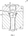
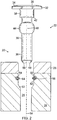
- Figures 1 and 2 illustrate partial cross-sectional views of one embodiment of the present apparatus 20 including a quick connect/disconnect pin connector 22.
- the pin connector 22 is disposed in a bore 24 ( Figure 2 ) extending through a first member 26 and a second member 28.
- the first member 26, also referred to herein as a plate 26 has a thickness substantially less than the thickness of the second member 28, also referred to herein as a housing 28.
- the pin connector 22 is described herein with reference to the plate 26, housing 28 and bore 24 shown in Figure 1 .
- embodiments of the present apparatus 20 are adapted for use in other fastening applications, such as for fastening toys, furniture, car parts, etc.
- the pin connector 22 includes an elongate shank 30 extending from a head portion 32.
- the head portion 32 is shaped substantially as a disk, and includes a chamfer 34 about an outer edge of a proximal surface 36.
- the head portion 32 may have substantially any shape, and may, for example, include features that facilitate engagement of the head portion 32 with one or more tools for inserting/withdrawing the pin connector 22 relative to the bore 24.
- the shank 30 is preferably unthreaded, and includes a proximal portion 38 having a first diameter and a distal portion 40 having a second, smaller diameter.
- the proximal and distal portions 38, 40 meet at a distally facing shoulder 42.
- An enlarged ball portion 44 interrupts the shank distal portion 40 and is spaced from the shoulder 42.
- the ball portion 44 is shaped substantially as a double-truncated sphere. A center of the sphere lies on the longitudinale axis 46 of the shank 30, such that the ball portion 44 protrudes evenly from all sides of the shank 30.
- a distal end 48 of the shank 30 includes a chamfer 50.
- the chamfer 50 guides the shank 30 into the bore 24 during the insertion process.
- Those of ordinary skill in the art will appreciate, however, that some embodiments of the present pin connector 22 may not include a chamfer at the distal end.
- the bore 24 in the housing 28 includes a proximally facing shoulder 52.
- the relative dimensions of the ball portion 44 and the shoulder 52 are configured such that the shoulder 52 limits the advancement of the pin connector 22 into the bore 24 when the ball portion abuts the shoulder.
- the shoulder 52 includes a radiused surface, which may in certain embodiments be matched with the radius of the ball portion 44.
- the shoulder 52 may have other configurations, and that in certain embodiments the shoulder 52 may be absent.
- the bore 24 in the housing 28 further includes an annular groove 54 positioned proximally of the shoulder 52.
- a bottom 56 of the groove 54 is nonparallel with respect to the bore longitudinal axis 58.
- a depth of the groove 54 (measured in a direction perpendicular to the bore longitudinal axis 58) is greater at a proximal side 60 of the groove 54 than at a distal side 62 of the groove 54.
- the groove bottom 56 thus tapers outwardly in a distal-to-proximal direction.
- a ring-shaped, canted coil spring 64 which may or may not be connected at its ends, seats within the groove 54.
- the relative dimensions of the spring 64 and groove 54 are chosen to meet the requirements of the application, as described in further detail below. In general, however, a width of the spring's coils is greater than the average depth of the groove 54 so that the coils protrude into the bore 24 when the pin connector 22 is not disposed within the bore 24.
- the ball portion 44 has a diameter that is closely matched to, but smaller than, the diameter of the bore 24 above the shoulder 52. Thus, in order to advance the pin connector 22 into the bore 24, or to withdraw the pin connector 22 from the bore 24, the ball portion 44 must displace the spring 64 as the ball portion 44 passes the spring 64.
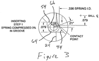
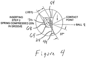
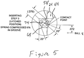
- Figures 3-6 The processes of inserting and withdrawing the pin connector 22 are illustrated in Figures 3-6 . These figures include dimensions, which reflect test observations. The principles of operation for the present apparatus 20 apply across a broad spectrum of configurations and dimensions. Accordingly, the dimensions provided in Figures 3-6 should not be interpreted as limiting.
- each coil in a canted coil spring is elliptical, and thus includes a major axis and a minor axis.
- the coils may elastically deform by compressing along their minor axes.
- compression along a coil's major axis causes plastic deformation.
- deflection and compression as applied to the spring 64 refer to compression of the spring 64 along its coils' minor axes.
- Figure 3 illustrates, in partial view, the pin connector 22 at an early stage of installation.
- the pin connector 22 has been advanced far enough into the bore 24 that the ball portion 44 makes contact with the spring 64 at a small circle of the ball portion 44 distal of its maximum diameter (as measured in a plane perpendicular to the pin connector's longitudinal axis 46).
- the spring minor axis 66 is generally parallel to the bore longitudinal axis 58 ( Figure 2 ).
- the spring 64 is undeflected by the ball portion 44, but is deflected as a result of the coil height being greater than the groove 54 width.
- the unstressed height of the coil 64 is 0.087 inch, while the compressed height of the coil 64 in Figure 3 is 0.079 inch.
- the light compression of the spring 64 helps to retain the spring 64 within the groove 54 when the pin connector 22 is absent.
- the dimensions of the groove 54 and spring 64 may be such that the groove 54 does not compress the spring 64 in the configuration of Figure 3 .
- Figure 4 in partial view, illustrates the configuration of the spring 64 at maximum deflection and rotation, which occurs as the maximum diameter of the ball portion 44 passes a point 68 below the vertical center 70 of the groove 54.
- the coil has deflected by compressing along its minor axis and has rotated clockwise.
- the maximum deflection and rotation of the spring 64 will occur at various positions of the ball portion 44 depending upon the relative dimensions of the ball portion 44, the groove 54, and the spring 64.
- the maximum deflection and rotation of the spring 64 may, for example, occur when the maximum diameter of the ball portion 44 is at the groove vertical center 70, above the groove vertical center 70, or below the groove vertical center.
- the configuration illustrated in Figure 4 is just one example.
- the taper bottom groove 54 facilitates the rotation of the coil 64 as the pin connector 22 is inserted into the bore 24.
- the taper bottom groove 54 also retards the reverse rotation of the coil 64 as the pin connector 22 is withdrawn from the bore 24. Consequently, greater force is required to remove the pin connector 22 from the bore 24 than is required to insert the pin connector 22 into the bore 24.
- the magnitude of the difference between the insertion force and the removal force can be adjusted by adjusting the angle of the taper bottom groove 54, which in the illustrated embodiment is 20°.
- the spring 64 When the pin connector 22 occupies the position illustrated in Figure 1 , the spring 64 is deflected and rotated as shown in Figure 5 . The resilience of the spring 64 creates a spring reaction force F S that squeezes the ball portion 44. With reference to Figure 1 , the spring force F S acts in a direction toward the center 72 of the ball portion 44. F S resolves into a radial component F R (perpendicular to the shank longitudinal axis 46) and an axial component F A (parallel to the shank longitudinal axis 46). The axial component F A retains the pin connector 22 within the bore 24 by counteracting any oppositely directed force that would tend to pull the pin connector 22 out of the bore 24.
- a withdrawal force F W is applied to the pin connector 22 as shown in Figure 6 .
- F W acts in a direction opposite F A , and must be greater than F A in order for the pin connector 22 to begin to withdraw from the bore 24.
- the squeezing force of the spring 64 on the ball portion 44, and thus the axial component F A increases as the diameter of the ball portion 44 in contact with the spring 64 increases.
- the taper bottom groove 54 resists spring rotation in the direction necessary to withdraw the pin (counterclockwise in Figure 6 ).
- F W must overcome the axial component to withdraw the pin connector 22 from the bore 24.
- an aspect of the present embodiments is a method for retaining a first member to a second member by requiring an incrementally increasing force to remove a pin from a bore that holds the two members together, the force increasing to a maximum value when the spring contacts the ball portion along a maximum diameter measured at a plane perpendicular to the longitudinal axis of the pin.
- the invention is also understood to include a fastening assembly that requires an insertion force applied to a pin connector to deflect a spring from a first deflection to a maximum deflection and then drop to a value between the first deflection and the maximum deflection when the pin connector is attached to a housing.
- the pin connector comprises a shank and an enlarged ball joint disposed along a length of the shank.
- the shank does not incorporate threads or at least threads proximal of the enlarged ball joint.
- the magnitude of the forces F S , F R , F A , F W depends upon many factors, including the spring constant, the relative dimensions of the spring 64 and the groove 54, the relative dimensions of the spring 64 and the ball portion 44, the distance that the pin connector 22 advances into the bore 24 (which is influenced by the thickness of the plate 26, among other factors), the wire diameter of the spring 64, and other factors. These factors are selected to provide a desired range for F W for each application. For example, when the groove 54 width is greater than the coil height, the spring 64 exerts less force on the pin connector 22 because there is free space within the groove 54 into which the spring 64 may deform.
- the groove 54 width when the groove 54 width is less than the coil height, the spring 64 exerts greater force on the pin connector 22 because there is no free space within the groove 54 into which spring 64 may deform.
- the groove 54 width may be selected to be less than the coil height.
- F W is also influenced by the location of the contact point between the spring 64 and the ball portion 44.
- the contact point is located 20° from the major axis 74 of the coil 64.
- the magnitude of F W decreases.
- the magnitude of F W increases.
- the taper bottom groove 54 causes this effect, which is explained in detail in U.S. Patent Nos. 4,678,210 ; 5,082,390 ; 5,411,348 ; 5,545,842 ; 6,749,358 ; 6,835,084 ; 7,070,455 and 7,195,523 .
- Embodiments of the present pin connector 22 advantageously provide the flexibility to tolerate variations in thickness in either or both of the first and second members 26, 28.
- the pin connector 22 provides a force tending to hold the first and second members 26, 28 together (a retaining force) as long as the spring 64 contacts the ball portion 44 and the spring 64 is located proximally of the maximum diameter of the ball portion 44.
- the pin connector 22 can retain the plate 26 on the housing 28 even if the plate 26 varies in thickness. If the plate 26 is thinner than expected, then the pin connector 22 simply extends farther into the bore 24, and if the plate 26 is thicker than expected then the pin connector 22 does not extend as far into the bore 24.
- an aspect of the present invention is understood to include an assembly for connecting a first member to a second member by incorporating a groove in the second member, which is located further away from a head portion on a pin connector than the first member.
- variation in the thickness of the first member and/or the thickness of the second member from a set or first predetermined value changes the location at which a spring is deflected by a ball joint.
- a method is also understood to be provided by using the assembly to fasten a first member to a second member in which a step is included that requires deflecting a spring with a ball joint located on a shank of a connector pin.
- Embodiments of the present pin connector 22 advantageously provide the ability to quickly connect objects that are to be secured together and to disconnect the same objects.
- to secure the plate 26 to the housing 28 one simply aligns the bores 24 in each member 26, 28 and inserts the pin connector 22 by applying a distally directed axial force to the pin connector 22.
- the axial force may be applied with digital pressure, or, for applications requiring a strong retaining force, with a rubber mallet, for example.
- the pin connector 22 To remove the pin connector 22 from the bore 24, one applies a proximally directed axial force to the pin connector 22, as by prying the head away from the plate 26 with a flathead screwdriver. Once the maximum diameter of the ball portion 44 clears the spring 64 the pin connector 22 pops right out of the bore 24 due to the squeezing force applied to the ball portion 44 by the spring 64. Again, there is no need for time consuming rotation of the connector.
- the head portion 22 may include surface features (not shown) that engage a pulling tool, such as a pin handle or an undercut designed for gripping.
- a further feature of the present invention is understood to include a method for securing a first member to a second member by inserting a connector pin into a bore of the first member and the second member without rotating the pin for engagement. Engagement is instead provided by deflecting a spring during the insertion step.
- the spring exerts a force on a ball joint located on the shank of the connector pin to provide a gripping force on the connector pin.
- the quick connect/disconnect feature of the present embodiments is particularly advantageous in applications where many connectors are required to secure two members together. This feature is also advantageous in tight spaces where there is little room in which to manipulate the tools necessary to rotate threaded fasteners.
Landscapes
- Engineering & Computer Science (AREA)
- General Engineering & Computer Science (AREA)
- Mechanical Engineering (AREA)
- Snaps, Bayonet Connections, Set Pins, And Snap Rings (AREA)
Claims (15)
- Vorrichtung zum aneinander Befestigen eines ersten Elements [26] und eines zweiten Elements [28], wobei die Vorrichtung umfasst:das erste und das zweite Element [26, 28], die eine Bohrung [24] aufweisen, die durch wenigstens eines von dem ersten und dem zweiten Element [26, 28] und wenigstens teilweise durch das andere von dem ersten und dem zweiten Element [26, 28] verläuft;gekennzeichnet durcheinen Stiftverbinder [22] umfassendwobei die Vorrichtung so gestaltet ist, dass die Feder eine drückende Kraft auf den Kugelteil ausübt, wenn der Stiftverbinder in der Bohrung angeordnet ist.einen Kopfteil [32] mit einem ersten Durchmesser;einen langgestreckten Schaft [30], der sich von dem Kopfteil [32]aus erstreckt, wobei der Schaft [30] wenigstens einen ersten Teil mit einem zweiten Durchmesser aufweist, der kleiner als der erste Durchmesser ist; undeinen vergrößerten Kugelteil [44], der entlang des Schafts [30] angeordnet ist, wobei der Kugelteil [44] im Wesentlichen als zweifach abgeflachte Kugel gestaltet ist und einen dritten Durchmesser aufweist, der kleiner als der erste Durchmesser aber größer als der zweite Durchmesser ist;eine Ringnut in dem zweiten Element, wobei die Ringnut um die Bohrung in dem zweiten Element verläuft; undeine Canted-Coil-Feder, die in der Nut angeordnet ist;
- Vorrichtung gemäß Anspruch 1, wobei der Stiftverbinder [22] gewindelos ist.
- Vorrichtung gemäß Anspruch 1 oder Anspruch 2, wobei die Nut [54] eine konische untere Oberfläche aufweist.
- Vorrichtung gemäß einem der Ansprüche 1 bis 3, wobei das erste Element [26] zwischen dem Kopfteil [32] und dem zweiten Element [28] angeordnet ist.
- Vorrichtung gemäß einem der vorstehenden Ansprüche, wobei der Kopfteil [32] einen ersten Durchmesser aufweist; der Schaft [30] sich von dem Kopfteil [32] aus erstreckt ; der Schaft [30] wenigstens einen ersten Teil mit einem zweiten Durchmesser aufweist, der kleiner als der erste Durchmesser ist; und
der Kugelabschnitt [44] im Wesentlichen als zweifach abgeflachte Kugel gestaltet ist und einen dritten Durchmesser aufweist, der kleiner als der erste Durchmesser aber größer als der zweite Durchmesser ist. - Vorrichtung gemäß einem der vorstehenden Ansprüche, wobei die Canted-Coil-Feder [64] eine drückende Kraft [Fs] auf den Kugelabschnitt [44] ausübt, wobei die drückende Kraft [Fs] sowohl einwärts radial [Fr] als auch distal longitudinal [Fa] gerichtete Kraftkomponenten aufweist.
- Vorrichtung gemäß einem der vorstehenden Ansprüche, wobei der Schaft [30] einen proximalen Teil [38] und einen distalen Teil [40] aufweist und wobei der proximale und der distale Teil unterschiedliche Durchmesser aufweisen.
- Vorrichtung gemäß Anspruch 7, wobei das distale Ende [48] des Schafts [30] eine Abschrägung [50] aufweist.
- Verfahren zum Befestigen eines ersten Elements [26] an einem zweiten Element [28], wobei das Verfahren dadurch gekennzeichnet ist, dass es umfasst:Einführen eines Stifts [22], der einen Schaft [30], einen Kopfteil [32] und einen Kugelabschnitt [44], der distal bezogen auf den Kopfteil [32] entlang des Schafts [30] angeordnet ist, umfasst, in eine Bohrung [24] des ersten Elements [26] und eine Bohrung [24] des zweiten Elements [28], wobei das zweite Element [28] eine in der Bohrung [24] angeordnete Nut [54] und eine darin angeordnete Canted-Coil-Feder [64] aufweist;Auslenken der Canted-Coil-Feder [64] von einer ersten Auslenkung in eine zweite Auslenkung und, wenn der Kugelabschnitt [44] in Kontakt mit der Feder [64] kommt und sich in eine End-Ruheposition bewegt, in eine dritte Auslenkung;wobei die dritte Auslenkung kleiner als die zweite Auslenkung ist und wobei die Canted-Coil-Feder [64] gegen den Kugelabschnitt [44] verspannt ist, um den Kugelabschnitt [44] und den Schaft [30] an dem zweiten Element [28] zu befestigen.
- Verfahren gemäß Anspruch 9, wobei der Schaft [30] gewindelos ist.
- Verfahren gemäß Anspruch 9 oder 10, wobei die Canted-Coil-Feder [64] eine radiale Canted-Coil-Feder ist.
- Verfahren gemäß einem der Ansprüche 9 bis 11, wobei die Federauslenkung Kraftkomponenten sowohl in die einwärts radiale [Fr] als auch in die distal longitudinale [Fa] Richtung ausübt, um den Kugelabschnitt [44] und den Schaft [30] an dem zweiten Element [28] festzuhalten.
- Verfahren gemäß einem der Ansprüche 9 bis 12, wobei die Bohrung [24] des ersten Elements [26] und die Bohrung [24] des zweiten Elements [28] fluchten, um eine gemeinsame Bohrung [24] zu bilden.
- Verfahren gemäß einem der Ansprüche 9 bis 13, wobei das erste Element [26] eine Dicke aufweist und das zweite Element [28] eine Dicke aufweist und wobei die Dicke des zweiten Elements [28] größer als die Dicke des ersten Elements ist.
- Verfahren gemäß einem der Ansprüche 9 bis 14, wobei die Nut [54] eine konische untere Oberfläche aufweist.
Applications Claiming Priority (2)
| Application Number | Priority Date | Filing Date | Title |
|---|---|---|---|
| US9707608P | 2008-09-15 | 2008-09-15 | |
| PCT/US2009/056682 WO2010030897A2 (en) | 2008-09-15 | 2009-09-11 | Apparatus including a pin connector for securing a first member and a second member to one another, and associated methods |
Publications (3)
| Publication Number | Publication Date |
|---|---|
| EP2334937A2 EP2334937A2 (de) | 2011-06-22 |
| EP2334937A4 EP2334937A4 (de) | 2013-02-27 |
| EP2334937B1 true EP2334937B1 (de) | 2017-04-12 |
Family
ID=42005769
Family Applications (1)
| Application Number | Title | Priority Date | Filing Date |
|---|---|---|---|
| EP09813683.1A Not-in-force EP2334937B1 (de) | 2008-09-15 | 2009-09-11 | Vorrichtung mit einem stiftstecker zur befestigung eines ersten elements und eines zweiten elements aneinander sowie entsprechende verfahren |
Country Status (3)
| Country | Link |
|---|---|
| US (1) | US8196271B2 (de) |
| EP (1) | EP2334937B1 (de) |
| WO (1) | WO2010030897A2 (de) |
Families Citing this family (11)
| Publication number | Priority date | Publication date | Assignee | Title |
|---|---|---|---|---|
| CN102052367B (zh) * | 2011-01-24 | 2012-03-07 | 江铃汽车股份有限公司 | 扣钉组件 |
| US20120301248A1 (en) * | 2011-05-25 | 2012-11-29 | Nuvasive, Inc. | System and Method for Fastening Objects Together |
| US9829028B2 (en) * | 2012-11-15 | 2017-11-28 | Bal Seal Engineering, Inc. | Connectors with a pin, a housing, and one or more springs |
| CN103032435A (zh) * | 2012-12-12 | 2013-04-10 | 浙江恒成硬质合金有限公司 | 自锁式硬质合金复合芯棒 |
| US10181668B2 (en) | 2016-06-24 | 2019-01-15 | Bal Seal Engineering, Inc. | Spring contacts and related methods |
| USD807158S1 (en) * | 2016-06-30 | 2018-01-09 | Fareast Metal International Co., Ltd | Pull-out dowel pin |
| CN106545558B (zh) * | 2016-10-30 | 2018-08-07 | 山西汾西重工有限责任公司 | 一种限位机构及限位机构解除方法 |
| CN107327458A (zh) * | 2017-08-14 | 2017-11-07 | 苏州顺时特机械科技有限公司 | 一种多功能活动螺栓 |
| CN108316547B (zh) * | 2018-03-27 | 2023-07-14 | 长春工程学院 | 组合式复合保温墙板 |
| CN110594258B (zh) * | 2019-08-30 | 2025-01-17 | 泉州极简机器人科技有限公司 | 床板的固定结构及电动床 |
| KR102354634B1 (ko) * | 2020-07-24 | 2022-01-24 | (주)화인 | 열전달 프레임 및 이를 구비한 유체 라인 히팅 자켓 |
Family Cites Families (36)
| Publication number | Priority date | Publication date | Assignee | Title |
|---|---|---|---|---|
| US829837A (en) * | 1905-09-06 | 1906-08-28 | Martin William F | Garment-fastener. |
| US2062057A (en) * | 1934-09-21 | 1936-11-24 | William H Hobby | Automobile license plate holder |
| FR851146A (fr) | 1938-03-03 | 1940-01-03 | Dispositif de verrouillage pour axe de liaison entre pièces constitutives de chaînes d'isolateurs de suspension, et autres applications | |
| US3494244A (en) * | 1967-10-24 | 1970-02-10 | Wasco Inc | Fastener |
| US3551963A (en) * | 1968-08-16 | 1971-01-05 | Walter W Mosher Jr | Self-locking snap fastener |
| US3610063A (en) * | 1969-11-07 | 1971-10-05 | Lincoln Logotype Co Inc | Spring detent hub |
| JPS51251B2 (de) * | 1972-08-16 | 1976-01-06 | ||
| US3910566A (en) * | 1974-05-15 | 1975-10-07 | Case Co J I | Coil spring detent assembly |
| US4655462A (en) | 1985-01-07 | 1987-04-07 | Peter J. Balsells | Canted coiled spring and seal |
| JPS62111409U (de) * | 1985-12-28 | 1987-07-16 | ||
| US4678210A (en) | 1986-08-15 | 1987-07-07 | Peter J. Balsells | Loading and locking mechanism |
| US4804290A (en) * | 1986-08-22 | 1989-02-14 | Peter J. Balsells | Latching and sealing device |
| US4777705A (en) * | 1987-11-02 | 1988-10-18 | Ingram Oran D | Shoe fastener |
| US4915366A (en) | 1988-04-25 | 1990-04-10 | Peter J. Balsells | Outside back angle canted coil spring |
| US5160122A (en) | 1990-03-20 | 1992-11-03 | Peter J. Balsells | Coil spring with an elastomer having a hollow coil cross section |
| US4876781A (en) | 1988-04-25 | 1989-10-31 | Peter J. Balsells | Method of making a garter-type axially resilient coiled spring |
| US4907788A (en) | 1988-04-25 | 1990-03-13 | Peter J. Balsells | Dual concentric canted-coil spring apparatus |
| US4826144A (en) | 1988-04-25 | 1989-05-02 | Peter J. Balsells | Inside back angle canted coil spring |
| US4964204A (en) | 1988-04-25 | 1990-10-23 | Peter J. Balsells | Method for making a garter-type axially-resilient coil spring |
| US5139243A (en) | 1990-07-30 | 1992-08-18 | Peter J. Balsells | Axial canted coil springs in sinusoidal form |
| US5082390A (en) | 1991-01-22 | 1992-01-21 | Peter J. Balsells | Latching, holding and locking spring apparatus |
| US5411348A (en) | 1993-10-26 | 1995-05-02 | Bal Seal Engineering Company, Inc. | Spring mechanism to connect, lock and unlock, members |
| US5545842A (en) | 1993-10-26 | 1996-08-13 | Bal Seal Engineering Company, Inc. | Radially mounted spring to connect, lock and unlock, and for snap-on fastening, and for mechanical, electromagnetic shielding, electrical conductivity, and thermal dissipation with environmental sealing |
| US5503375A (en) | 1994-11-09 | 1996-04-02 | Bal Seal Engineering Company, Inc. | Coil spring with ends adapted for coupling without welding |
| US5580204A (en) * | 1995-03-07 | 1996-12-03 | Textron Inc. | Panel attachment system |
| US5709371A (en) | 1995-06-02 | 1998-01-20 | Bal Seal Engineering Company, Inc. | Coil spring with ends adapted for coupling without welding |
| US5791638A (en) | 1996-09-13 | 1998-08-11 | Bal Seal Engineering Company, Inc. | Coil spring with ends adapted for coupling without welding |
| US6324731B1 (en) * | 1998-02-05 | 2001-12-04 | Illinois Tool Works Inc. | Isolator fan fastener |
| JP2005510849A (ja) | 2001-11-21 | 2005-04-21 | バル・シール・エンジニアリング・カンパニー・インコーポレーテッド | 工具を使用せずに接続及び接続解除を行える係脱可能で導電能力を備えたコネクタ |
| WO2003046392A2 (en) * | 2001-11-21 | 2003-06-05 | Bal Seal Engineering Co., Inc. | Connector with radial spring |
| WO2003071635A1 (en) | 2002-02-15 | 2003-08-28 | Bal Seal Engineering Co., Inc. | Medically implantable electrical connector with constant conductivity |
| US7055812B2 (en) | 2002-09-30 | 2006-06-06 | Bal Seal Engineering Co., Inc. | Canted coil springs various designs |
| US8167285B2 (en) * | 2003-06-04 | 2012-05-01 | Bal Seal Engineering Co., Inc. | Spring latching connectors radially and axially mounted |
| US7070455B2 (en) | 2004-02-23 | 2006-07-04 | Bal Seal Engineering Co., Inc. | Stackable assembly for direct connection between a pulse generator and a human body |
| WO2006026186A2 (en) | 2004-08-26 | 2006-03-09 | Bal Seal Engineering Co., Inc. | Electrical conductive path for a medical electronics device |
| US20060228166A1 (en) * | 2005-04-05 | 2006-10-12 | Bal Seal Engineering Co., Inc. | Ball holding, latching and locking applications using radial and axial springs |
-
2009
- 2009-09-11 EP EP09813683.1A patent/EP2334937B1/de not_active Not-in-force
- 2009-09-11 WO PCT/US2009/056682 patent/WO2010030897A2/en not_active Ceased
- 2009-09-14 US US12/559,227 patent/US8196271B2/en active Active
Also Published As
| Publication number | Publication date |
|---|---|
| WO2010030897A3 (en) | 2010-06-10 |
| WO2010030897A2 (en) | 2010-03-18 |
| US8196271B2 (en) | 2012-06-12 |
| EP2334937A2 (de) | 2011-06-22 |
| EP2334937A4 (de) | 2013-02-27 |
| US20100064490A1 (en) | 2010-03-18 |
Similar Documents
| Publication | Publication Date | Title |
|---|---|---|
| US8196271B2 (en) | Apparatus including a pin connector for securing a first member and a second member to one another, and associated methods | |
| US8496421B1 (en) | Ferrule lock nuts | |
| US5030051A (en) | Screw rivet | |
| EP1260719B1 (de) | Lösbarer und wiederverwendbarer Befestiger | |
| CN100387399C (zh) | 单面紧固件和用于单面紧固件安装的凸头组件 | |
| JP2007530149A (ja) | 摘出用ドライバー | |
| EP0736143A1 (de) | Vorrichtung zum herstellen von verbindungen | |
| JP2007514113A (ja) | 内部配置型直動式ファスナーシステム | |
| AU2002350958B2 (en) | Method of fastening | |
| CN111406351A (zh) | 线缆固定装置 | |
| AU652850B2 (en) | Compressible screw-type locking mechanism | |
| WO2017035439A1 (en) | Conduit retaining structure for conduit fitting | |
| US20180195651A1 (en) | Component retaining structure for conduit fitting | |
| US5168902A (en) | Tube plugging method | |
| EP0515026B1 (de) | Blindbefestiger | |
| US20140109381A1 (en) | Fastener retention system | |
| EP2268959A1 (de) | System und verfahren zum befestigen von objekten aneinander | |
| US6676347B2 (en) | Blind fastener and drive nut assembly | |
| GB2340908A (en) | Expandable screw-threaded fastener | |
| WO1994012799A1 (en) | Blind fastener | |
| US20060193711A1 (en) | Threaded bolt fastener | |
| AU2024278347A1 (en) | Multi-piece fastener comprising a tapered threaded portion and method of fastening | |
| WO2020016885A1 (en) | Nut stopper for loosening prevention | |
| US4812097A (en) | Spring action fastener | |
| US20260043434A1 (en) | Fastener |
Legal Events
| Date | Code | Title | Description |
|---|---|---|---|
| PUAI | Public reference made under article 153(3) epc to a published international application that has entered the european phase |
Free format text: ORIGINAL CODE: 0009012 |
|
| 17P | Request for examination filed |
Effective date: 20110407 |
|
| AK | Designated contracting states |
Kind code of ref document: A2 Designated state(s): AT BE BG CH CY CZ DE DK EE ES FI FR GB GR HR HU IE IS IT LI LT LU LV MC MK MT NL NO PL PT RO SE SI SK SM TR |
|
| AX | Request for extension of the european patent |
Extension state: AL BA RS |
|
| DAX | Request for extension of the european patent (deleted) | ||
| A4 | Supplementary search report drawn up and despatched |
Effective date: 20130125 |
|
| RIC1 | Information provided on ipc code assigned before grant |
Ipc: F16B 21/10 20060101ALI20130121BHEP Ipc: F16B 21/08 20060101AFI20130121BHEP Ipc: F16B 21/06 20060101ALI20130121BHEP Ipc: F16B 1/02 20060101ALI20130121BHEP |
|
| 17Q | First examination report despatched |
Effective date: 20150707 |
|
| GRAP | Despatch of communication of intention to grant a patent |
Free format text: ORIGINAL CODE: EPIDOSNIGR1 |
|
| INTG | Intention to grant announced |
Effective date: 20160223 |
|
| GRAS | Grant fee paid |
Free format text: ORIGINAL CODE: EPIDOSNIGR3 |
|
| RIN1 | Information on inventor provided before grant (corrected) |
Inventor name: BALSELLS, PETER J. |
|
| GRAA | (expected) grant |
Free format text: ORIGINAL CODE: 0009210 |
|
| AK | Designated contracting states |
Kind code of ref document: B1 Designated state(s): AT BE BG CH CY CZ DE DK EE ES FI FR GB GR HR HU IE IS IT LI LT LU LV MC MK MT NL NO PL PT RO SE SI SK SM TR |
|
| RAP1 | Party data changed (applicant data changed or rights of an application transferred) |
Owner name: BAL SEAL ENGINEERING, INC. |
|
| REG | Reference to a national code |
Ref country code: GB Ref legal event code: FG4D |
|
| REG | Reference to a national code |
Ref country code: CH Ref legal event code: EP |
|
| REG | Reference to a national code |
Ref country code: IE Ref legal event code: FG4D |
|
| REG | Reference to a national code |
Ref country code: AT Ref legal event code: REF Ref document number: 884216 Country of ref document: AT Kind code of ref document: T Effective date: 20170515 |
|
| REG | Reference to a national code |
Ref country code: DE Ref legal event code: R096 Ref document number: 602009045442 Country of ref document: DE |
|
| REG | Reference to a national code |
Ref country code: FR Ref legal event code: PLFP Year of fee payment: 9 |
|
| REG | Reference to a national code |
Ref country code: NL Ref legal event code: MP Effective date: 20170412 |
|
| REG | Reference to a national code |
Ref country code: LT Ref legal event code: MG4D |
|
| REG | Reference to a national code |
Ref country code: AT Ref legal event code: MK05 Ref document number: 884216 Country of ref document: AT Kind code of ref document: T Effective date: 20170412 |
|
| PG25 | Lapsed in a contracting state [announced via postgrant information from national office to epo] |
Ref country code: NL Free format text: LAPSE BECAUSE OF FAILURE TO SUBMIT A TRANSLATION OF THE DESCRIPTION OR TO PAY THE FEE WITHIN THE PRESCRIBED TIME-LIMIT Effective date: 20170412 |
|
| PG25 | Lapsed in a contracting state [announced via postgrant information from national office to epo] |
Ref country code: NO Free format text: LAPSE BECAUSE OF FAILURE TO SUBMIT A TRANSLATION OF THE DESCRIPTION OR TO PAY THE FEE WITHIN THE PRESCRIBED TIME-LIMIT Effective date: 20170712 Ref country code: FI Free format text: LAPSE BECAUSE OF FAILURE TO SUBMIT A TRANSLATION OF THE DESCRIPTION OR TO PAY THE FEE WITHIN THE PRESCRIBED TIME-LIMIT Effective date: 20170412 Ref country code: ES Free format text: LAPSE BECAUSE OF FAILURE TO SUBMIT A TRANSLATION OF THE DESCRIPTION OR TO PAY THE FEE WITHIN THE PRESCRIBED TIME-LIMIT Effective date: 20170412 Ref country code: GR Free format text: LAPSE BECAUSE OF FAILURE TO SUBMIT A TRANSLATION OF THE DESCRIPTION OR TO PAY THE FEE WITHIN THE PRESCRIBED TIME-LIMIT Effective date: 20170713 Ref country code: HR Free format text: LAPSE BECAUSE OF FAILURE TO SUBMIT A TRANSLATION OF THE DESCRIPTION OR TO PAY THE FEE WITHIN THE PRESCRIBED TIME-LIMIT Effective date: 20170412 Ref country code: LT Free format text: LAPSE BECAUSE OF FAILURE TO SUBMIT A TRANSLATION OF THE DESCRIPTION OR TO PAY THE FEE WITHIN THE PRESCRIBED TIME-LIMIT Effective date: 20170412 Ref country code: AT Free format text: LAPSE BECAUSE OF FAILURE TO SUBMIT A TRANSLATION OF THE DESCRIPTION OR TO PAY THE FEE WITHIN THE PRESCRIBED TIME-LIMIT Effective date: 20170412 |
|
| PG25 | Lapsed in a contracting state [announced via postgrant information from national office to epo] |
Ref country code: BG Free format text: LAPSE BECAUSE OF FAILURE TO SUBMIT A TRANSLATION OF THE DESCRIPTION OR TO PAY THE FEE WITHIN THE PRESCRIBED TIME-LIMIT Effective date: 20170712 Ref country code: PL Free format text: LAPSE BECAUSE OF FAILURE TO SUBMIT A TRANSLATION OF THE DESCRIPTION OR TO PAY THE FEE WITHIN THE PRESCRIBED TIME-LIMIT Effective date: 20170412 Ref country code: LV Free format text: LAPSE BECAUSE OF FAILURE TO SUBMIT A TRANSLATION OF THE DESCRIPTION OR TO PAY THE FEE WITHIN THE PRESCRIBED TIME-LIMIT Effective date: 20170412 Ref country code: IS Free format text: LAPSE BECAUSE OF FAILURE TO SUBMIT A TRANSLATION OF THE DESCRIPTION OR TO PAY THE FEE WITHIN THE PRESCRIBED TIME-LIMIT Effective date: 20170812 Ref country code: SE Free format text: LAPSE BECAUSE OF FAILURE TO SUBMIT A TRANSLATION OF THE DESCRIPTION OR TO PAY THE FEE WITHIN THE PRESCRIBED TIME-LIMIT Effective date: 20170412 |
|
| REG | Reference to a national code |
Ref country code: DE Ref legal event code: R097 Ref document number: 602009045442 Country of ref document: DE |
|
| PG25 | Lapsed in a contracting state [announced via postgrant information from national office to epo] |
Ref country code: SK Free format text: LAPSE BECAUSE OF FAILURE TO SUBMIT A TRANSLATION OF THE DESCRIPTION OR TO PAY THE FEE WITHIN THE PRESCRIBED TIME-LIMIT Effective date: 20170412 Ref country code: DK Free format text: LAPSE BECAUSE OF FAILURE TO SUBMIT A TRANSLATION OF THE DESCRIPTION OR TO PAY THE FEE WITHIN THE PRESCRIBED TIME-LIMIT Effective date: 20170412 Ref country code: RO Free format text: LAPSE BECAUSE OF FAILURE TO SUBMIT A TRANSLATION OF THE DESCRIPTION OR TO PAY THE FEE WITHIN THE PRESCRIBED TIME-LIMIT Effective date: 20170412 Ref country code: EE Free format text: LAPSE BECAUSE OF FAILURE TO SUBMIT A TRANSLATION OF THE DESCRIPTION OR TO PAY THE FEE WITHIN THE PRESCRIBED TIME-LIMIT Effective date: 20170412 Ref country code: CZ Free format text: LAPSE BECAUSE OF FAILURE TO SUBMIT A TRANSLATION OF THE DESCRIPTION OR TO PAY THE FEE WITHIN THE PRESCRIBED TIME-LIMIT Effective date: 20170412 |
|
| PLBE | No opposition filed within time limit |
Free format text: ORIGINAL CODE: 0009261 |
|
| STAA | Information on the status of an ep patent application or granted ep patent |
Free format text: STATUS: NO OPPOSITION FILED WITHIN TIME LIMIT |
|
| PG25 | Lapsed in a contracting state [announced via postgrant information from national office to epo] |
Ref country code: IT Free format text: LAPSE BECAUSE OF FAILURE TO SUBMIT A TRANSLATION OF THE DESCRIPTION OR TO PAY THE FEE WITHIN THE PRESCRIBED TIME-LIMIT Effective date: 20170412 Ref country code: SM Free format text: LAPSE BECAUSE OF FAILURE TO SUBMIT A TRANSLATION OF THE DESCRIPTION OR TO PAY THE FEE WITHIN THE PRESCRIBED TIME-LIMIT Effective date: 20170412 |
|
| 26N | No opposition filed |
Effective date: 20180115 |
|
| REG | Reference to a national code |
Ref country code: CH Ref legal event code: PL |
|
| PG25 | Lapsed in a contracting state [announced via postgrant information from national office to epo] |
Ref country code: MC Free format text: LAPSE BECAUSE OF FAILURE TO SUBMIT A TRANSLATION OF THE DESCRIPTION OR TO PAY THE FEE WITHIN THE PRESCRIBED TIME-LIMIT Effective date: 20170412 Ref country code: SI Free format text: LAPSE BECAUSE OF FAILURE TO SUBMIT A TRANSLATION OF THE DESCRIPTION OR TO PAY THE FEE WITHIN THE PRESCRIBED TIME-LIMIT Effective date: 20170412 |
|
| REG | Reference to a national code |
Ref country code: IE Ref legal event code: MM4A |
|
| REG | Reference to a national code |
Ref country code: BE Ref legal event code: MM Effective date: 20170930 |
|
| PG25 | Lapsed in a contracting state [announced via postgrant information from national office to epo] |
Ref country code: LU Free format text: LAPSE BECAUSE OF NON-PAYMENT OF DUE FEES Effective date: 20170911 |
|
| PG25 | Lapsed in a contracting state [announced via postgrant information from national office to epo] |
Ref country code: CH Free format text: LAPSE BECAUSE OF NON-PAYMENT OF DUE FEES Effective date: 20170930 Ref country code: LI Free format text: LAPSE BECAUSE OF NON-PAYMENT OF DUE FEES Effective date: 20170930 Ref country code: IE Free format text: LAPSE BECAUSE OF NON-PAYMENT OF DUE FEES Effective date: 20170911 |
|
| REG | Reference to a national code |
Ref country code: FR Ref legal event code: PLFP Year of fee payment: 10 |
|
| PG25 | Lapsed in a contracting state [announced via postgrant information from national office to epo] |
Ref country code: BE Free format text: LAPSE BECAUSE OF NON-PAYMENT OF DUE FEES Effective date: 20170930 |
|
| PG25 | Lapsed in a contracting state [announced via postgrant information from national office to epo] |
Ref country code: MT Free format text: LAPSE BECAUSE OF NON-PAYMENT OF DUE FEES Effective date: 20170911 |
|
| PG25 | Lapsed in a contracting state [announced via postgrant information from national office to epo] |
Ref country code: HU Free format text: LAPSE BECAUSE OF FAILURE TO SUBMIT A TRANSLATION OF THE DESCRIPTION OR TO PAY THE FEE WITHIN THE PRESCRIBED TIME-LIMIT; INVALID AB INITIO Effective date: 20090911 |
|
| PG25 | Lapsed in a contracting state [announced via postgrant information from national office to epo] |
Ref country code: CY Free format text: LAPSE BECAUSE OF NON-PAYMENT OF DUE FEES Effective date: 20170412 |
|
| PG25 | Lapsed in a contracting state [announced via postgrant information from national office to epo] |
Ref country code: MK Free format text: LAPSE BECAUSE OF FAILURE TO SUBMIT A TRANSLATION OF THE DESCRIPTION OR TO PAY THE FEE WITHIN THE PRESCRIBED TIME-LIMIT Effective date: 20170412 |
|
| PG25 | Lapsed in a contracting state [announced via postgrant information from national office to epo] |
Ref country code: TR Free format text: LAPSE BECAUSE OF FAILURE TO SUBMIT A TRANSLATION OF THE DESCRIPTION OR TO PAY THE FEE WITHIN THE PRESCRIBED TIME-LIMIT Effective date: 20170412 |
|
| REG | Reference to a national code |
Ref country code: DE Ref legal event code: R081 Ref document number: 602009045442 Country of ref document: DE Owner name: BAL SEAL ENGINEERING, LLC, FOOTHILL RANCH, US Free format text: FORMER OWNER: BAL SEAL ENGINEERING, INC., FOOTHILL RANCH, CALIF., US Ref country code: DE Ref legal event code: R082 Ref document number: 602009045442 Country of ref document: DE Representative=s name: BIRD & BIRD LLP, DE |
|
| PG25 | Lapsed in a contracting state [announced via postgrant information from national office to epo] |
Ref country code: PT Free format text: LAPSE BECAUSE OF FAILURE TO SUBMIT A TRANSLATION OF THE DESCRIPTION OR TO PAY THE FEE WITHIN THE PRESCRIBED TIME-LIMIT Effective date: 20170412 |
|
| PGFP | Annual fee paid to national office [announced via postgrant information from national office to epo] |
Ref country code: GB Payment date: 20200902 Year of fee payment: 12 Ref country code: DE Payment date: 20200901 Year of fee payment: 12 Ref country code: FR Payment date: 20200812 Year of fee payment: 12 |
|
| REG | Reference to a national code |
Ref country code: DE Ref legal event code: R119 Ref document number: 602009045442 Country of ref document: DE |
|
| GBPC | Gb: european patent ceased through non-payment of renewal fee |
Effective date: 20210911 |
|
| PG25 | Lapsed in a contracting state [announced via postgrant information from national office to epo] |
Ref country code: GB Free format text: LAPSE BECAUSE OF NON-PAYMENT OF DUE FEES Effective date: 20210911 Ref country code: FR Free format text: LAPSE BECAUSE OF NON-PAYMENT OF DUE FEES Effective date: 20210930 Ref country code: DE Free format text: LAPSE BECAUSE OF NON-PAYMENT OF DUE FEES Effective date: 20220401 |