EP2335548B1 - Geschirrkorb für einen Spül- und/oder Desinfektionsautomaten mit einer Haltevorrichtung für Hohlgefäße - Google Patents
Geschirrkorb für einen Spül- und/oder Desinfektionsautomaten mit einer Haltevorrichtung für Hohlgefäße Download PDFInfo
- Publication number
- EP2335548B1 EP2335548B1 EP20100401198 EP10401198A EP2335548B1 EP 2335548 B1 EP2335548 B1 EP 2335548B1 EP 20100401198 EP20100401198 EP 20100401198 EP 10401198 A EP10401198 A EP 10401198A EP 2335548 B1 EP2335548 B1 EP 2335548B1
- Authority
- EP
- European Patent Office
- Prior art keywords
- dish rack
- clamping part
- holding device
- hoop
- holding
- Prior art date
- Legal status (The legal status is an assumption and is not a legal conclusion. Google has not performed a legal analysis and makes no representation as to the accuracy of the status listed.)
- Active
Links
Images

Classifications
-
- A—HUMAN NECESSITIES
- A47—FURNITURE; DOMESTIC ARTICLES OR APPLIANCES; COFFEE MILLS; SPICE MILLS; SUCTION CLEANERS IN GENERAL
- A47L—DOMESTIC WASHING OR CLEANING; SUCTION CLEANERS IN GENERAL
- A47L15/00—Washing or rinsing machines for crockery or tableware
- A47L15/42—Details
- A47L15/50—Racks ; Baskets
- A47L15/505—Inserts, e.g. for holding baby bottles, stemware or cups
-
- A—HUMAN NECESSITIES
- A47—FURNITURE; DOMESTIC ARTICLES OR APPLIANCES; COFFEE MILLS; SPICE MILLS; SUCTION CLEANERS IN GENERAL
- A47L—DOMESTIC WASHING OR CLEANING; SUCTION CLEANERS IN GENERAL
- A47L15/00—Washing or rinsing machines for crockery or tableware
- A47L15/42—Details
- A47L15/50—Racks ; Baskets
- A47L15/503—Racks ; Baskets with foldable parts
Definitions
- the present invention relates to a dish rack for a rinsing and / or disinfection machine with a holding device for hollow vessels such as vases, bottles and glasses, comprising a insertable into the hollow container holding part and a fastened to the dish rack clamping part, wherein the holding part is releasably secured to the clamping part and the clamping member is releasably supported on the dish rack, and wherein the holding member is formed as an elongated bracket, which consists of two elastically deformable legs, which are fixedly connected to each other at its upper end by a semicircular web.
- Such inserts for example dishwashing dishwashers, are generally formed with loops which form spaces for receiving plates and other items to be cleaned. Additionally or alternatively, hinged or fixed spike rows are available, which serve to accommodate smaller plates. On the spikes also hollow vessels can be inserted. From the DE 10 2005 044 264 A1 a dish rack with spikes is known, which are foldable from a functional position to a rest position.
- hollow vessel holders from the DE 10 2006 007 330 A1 known, which are formed of two preferably elastic rods which are adapted to be inserted together in the hollow vessel, wherein at one end of the rods a base for pivotally mounting the rods is provided. This base is swung together with the two upstanding bars in the floor level of the dish rack. For stable mounting of this fixture, the base must be placed at a crossing point of two perpendicular to each other extending wires of the dish rack.
- From the DE 10 2006 012 455 A1 is a holding device of the type mentioned in the form of a bottle rack known. This consists of two hinged spike rows, each of which is releasably mounted on a clampable frame.
- Object of the present invention is to provide a crockery basket with a hollow vessel holding device, whose use is expanded.
- the hollow vessel holding device has a holding part which can be inserted into the hollow vessel and a clamping part which can be fastened to the dish rack, wherein the holding part is detachably fastened to the clamping part. Due to the detachable holder, the area of use of the hollow vessel holding device on the dish rack is widened. Thus, the holding part, in particular if it is designed as an elongated bracket, are easily removed from the dish rack.
- the clamping part is U-shaped. This results in an easy-to-manufacture construction and it is mounted releasably on the dish rack in a simple manner. This makes it possible that one or more clamping parts can be permanently attached to the dish rack and only the bracket can be used if necessary.
- the solubility results in a simple manner in that the clamping part has at its webs outwardly directed grooves with which it is fixed to a protruding from the storage level loop or between two spikes of the dish rack.
- the bracket is pivotally supported on the clamping part between a set up from a storage level of the dish rack function position and at least one folded into the storage level of the dish rack rest position.
- the bracket has two perpendicular to its longitudinal axis elastically deformable leg, which are releasable for pivoting or removal by squeezing from a lock on the clamping part. The user can then remove the bracket completely on request, for. B. if it is to be cleaned manually.
- a simple mounting is possible if the bracket has at its legs each bent at right angles ends, which are received by openings in the clamping part.
- a very simple construction of the clamping part results when the openings are arranged in webs, of which at least one above the opening has a first longitudinal groove for holding the bracket in the functional position.
- the bracket is suitably designed as preferably plastic-coated wire bracket, the clamping part as a plastic part.
- FIGS. 5 to 7 a dish rack 11 is shown.
- the hanger 2 which in detail in FIG. 3 is shown, is designed as a plastic-coated wire loop. It consists of two elastically deformable legs 22, 23, which are connected at their upper end by a semi-circular web 24 firmly together. At their ends opposite the web 24 25 and 26, the two legs 22, 23 are each bent at right angles. These ends 25 and 26 serve to pivotally attach the bracket 2 to the clamping part. 3
- clamping part 3 is preferably formed as a U-shaped molding with a base web 31 and two projecting from the base web 31 side webs 32, 33.
- the clamping part 3 is circumferentially formed with a groove 34 so that the clamping part 3 in the correspondingly shaped loop 12 of the dish rack 11 can be inserted and latched.
- the clamping part 3 is designed in particular as a plastic clip.
- the mutually facing inner sides of the side bars 32 and 33 are each formed with a groove, in particular a U-shaped groove 35 and 36, respectively.
- a groove in particular a U-shaped groove 35 and 36, respectively.
- two openings 37 and 38 are arranged at the lower end of the side webs 32 and 33, just before their transition into the base web 31, two openings 37 and 38 are arranged. These take up the bent ends 25 and 26 of the bracket 2.
- the legs 22 and 23 are pressed in its lower portion in the grooves 35 and 36 and there in the in the FIGS. 1 . 5 and 6 illustrated functional position locked, in which the bracket 2 is erected from the storage level of the basket 11.
- the legs 22 When not in use, the legs 22 may and 23 of the bracket 2 compressed and in the in the Figures 2 and 7 shown rest position are pivoted, in which the bracket 2 is folded into the storage level of Geschirrtcorbs 11. Alternatively, the legs 22 and 23 can be further compressed until the ends 25 and 26 slide out of the openings 37 and 38 and the bracket 2 can be completely removed. In order to remove the entire holding device 1 from the dish rack 11, the user only has to pull on the bar 2, as a result of which the clamping part 3 slides out of its holder in the loop 12.
Landscapes
- Details Of Rigid Or Semi-Rigid Containers (AREA)
- Supports Or Holders For Household Use (AREA)
Description
- Die vorliegende Erfindung betrifft einen Geschirrkorb für einen Spül- und/oder Desinfektionsautomaten mit einer Haltevorrichtung für Hohlgefäße wie Vasen, Flaschen und Gläser, aufweisend ein in das Hohlgefäß einführbares Halteteil und ein an dem Geschirrkorb befestigbares Klemmteil, wobei das Halteteil am Klemmteil lösbar befestigt ist und das Klemmteil lösbar am Geschirrkorb gehaltert ist, und wobei das Halteteil als langgestreckter Bügel ausgebildet ist, welcher aus zwei elastisch verformbaren Schenkeln besteht, die an ihrem oberen Ende durch einen halbkreisförmigen Steg fest miteinander verbunden sind.
- Solche Einsätze, beispielsweise Geschirrkörbe von Spülmaschinen, sind im Allgemeinen mit Schlaufen ausgebildet, welche Zwischenräume zur Aufnahme von Tellern und anderem Reinigungsgut bilden. Zusätzlich oder alternativ sind klappbare oder feststehende Spikereihen vorhanden, die zur Aufnahme von kleineren Tellern dienen. Auf die Spikes können auch Hohlgefäße gesteckt werden. Aus der
DE 10 2005 044 264 A1 ist ein Geschirrkorb mit Spikes bekannt, welche von einer Funktionsstellung in eine Ruhestellung klappbar sind. - Größere Hohlgefäße, insbesondere Weißbiergläser, Laborgeschirr oder Vasen finden auf den kurzen Spikes nur einen schlechten Halt und können beim Ein- und Ausfahren des Geschirrkorbs oder beim Besprühen mit Spülflüssigkeit umkippen und dabei zerstört werden oder anderes Spülgut zerstören. Deshalb sind Hohlgefäßhalterungen aus der
DE 10 2006 007 330 A1 bekannt, die aus zwei vorzugsweise elastischen Stäben gebildet sind, welche geeignet sind, gemeinsam in das Hohlgefäß eingeführt zu werden, wobei an einem Ende der Stäbe eine Basis zur schwenkbaren Lagerung der Stäbe vorgesehen ist. Diese Basis wird zusammen mit den beiden nach oben stehenden Stäben in die Bodenebene des Geschirrkorbs umgeschwenkt. Zur stabilen Halterung dieser Haltevorrichtung muss die Basis an einem Kreuzungspunkt zweier senkrecht zueinander verlaufender Drähte des Geschirrkorbes aufgestellt werden. - Von der Anmelderin werden gattungsgemäße Hohlgefäßhaltevorrichtungen vertrieben, welche aus einem aus dem Korb ragenden Bügel und einem Klemmteil bestehen. Der Bügel ist starr mit dem Klemmteil verbunden. Deshalb muss die gesamte Haltevorrichtung von dem Korb gelöst werden, wenn sie nicht benötigt wird.
- Aus der
DE 10 2006 012 455 A1 ist eine Haltevorrichtung der eingangs genannten Art in Form eines Flaschengestells bekannt. Diese besteht aus zwei klappbaren Spikereihen, von denen jede lösbar an einem klemmbaren Rahmen gehaltert ist. - Aufgabe der vorliegenden Erfindung ist es, einen Geschirrkorb mit einer Hohlgefäßhaltevorrichtung zu schaffen, deren Verwendungsmöglichkeit erweitert ist.
- Diese Aufgabe wird durch einen Geschirrkorb mit den Merkmalen des Anspruchs 1 gelöst.
- Die Hohlgefäßhaltevorrichtung weist ein in das Hohlgefäß einführbares Halteteil und ein an dem Geschirrkorb befestigbares Klemmteil auf, wobei das Halteteil am Klemmteil lösbar befestigt ist. Durch die lösbare Halterung ist der Einsatzbereich der Hohlgefäßhaltevorrichtung an dem Geschirrkorb erweitert. So kann das Halteteil, insbesondere wenn es als langgestreckter Bügel ausgebildet ist, in einfacher Weise vom Geschirrkorb entfernt werden. Außerdem ist das Klemmteil u-förmig ausgebildet. Hierdurch ergibt sich ein einfach zu fertigender Aufbau und es ist in einfacher Weise lösbar am Geschirrkorb gehaltert. Dadurch ist es möglich, dass eines oder mehrere Klemmteile dauerhaft an dem Geschirrkorb angebracht sein können und nur die Bügel bei Bedarf eingesetzt werden. Die Lösbarkeit ergibt sich in einfacher Weise dadurch, dass das Klemmteil an seinen Stegen nach außen gerichtete Nuten besitzt, mit denen es an einer aus der Ablageebene herausragenden Schlaufe oder zwischen zwei Spikes des Geschirrkorbs fixierbar ist.
- In einer besonders vorteilhaften Ausgestaltung der Erfindung ist der Bügel an dem Klemmteil zwischen einer aus einer Ablageebene des Geschirrkorbs aufgestellten Funktionsstellung und mindestens einer in die Ablageebene des Geschirrkorbs umgeklappten Ruhestellung schwenkbar gehaltert. Auf diese Weise entfällt für den Benutzer die Notwendigkeit, die Haltevorrichtung aus dem Geschirrkorb zu entfernen, wenn sie nicht gebraucht wird. In einfachster Weise wird dies dadurch erreicht, dass der Bügel zwei senkrecht zu seiner Längsachse elastisch verformbare Schenkel aufweist, die zum Verschwenken oder Entnehmen durch Zusammendrücken aus einer Arretierung an dem Klemmteil lösbar sind. Der Benutzer kann dann auf Wunsch den Bügel auch vollständig entnehmen, z. B. wenn er manuell gereinigt werden soll. Eine einfache Halterung ist möglich, wenn der Bügel an seinen Schenkeln jeweils rechtwinklig abgekröpfte Enden aufweist, welche von Öffnungen im Klemmteil aufgenommen werden. Ein sehr einfacher Aufbau des Klemmteils ergibt sich, wenn die Öffnungen in Stegen angeordnet sind, von denen mindestens einer oberhalb der Öffnung eine erste Längsnut zur Halterung des Bügels in der Funktionsstellung besitzt.
- Der Bügel ist in zweckmäßiger Weise als vorzugsweise kunststoffummantelter Drahtbügel ausgebildet, das Klemmteil als Kunststoffteil.
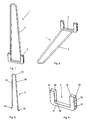
- Die Erfindung wird nachfolgend anhand von Ausführungsbeispielen mit Bezug auf die beigefügten Zeichnungen näher erläutert. Es zeigen:
- Figur 1
- eine perspektivische Darstellung einer Hohlgefäßhaltevorrichtung mit aufgerichtetem Bügel,
- Figur 2
- die Haltevorrichtung aus
Figur 1 mit umgelegtem Bügel, - Figur 3
- eine perspektivische Darstellung eines Bügels,
- Figur 4
- eine perspektivische Ansicht eines Klemmteils,
- Figur 5
- eine perspektivische Ansicht eines Geschirrkorbs mit eingesetzter Haltevorrichtung,
- Figur 6
- eine Ausschnittvergrößerung des Geschirrkorbs aus
Figur 5 , - Figur 7
- eine Ausschnittvergrößerung des Geschirrkorbs mit umgeklapptem Bügel.
- In den
Figuren 1 und 2 ist mit 1 insgesamt eine Hohlgefäßhaltevorrichtung für einen Geschirrkorb eines Spül- und/oder Desinfektionsautomaten bezeichnet. Die Hohlgefäßhaltevorrichtung 1 dient der kippsicheren Halterung von nicht dargestellten Hohlgefäßen wie Laborgeschirr, Vasen oder großen Gläsern. Sie besteht aus einem langgestreckten, in das Hohlgefäß einführbaren Bügel 2, sowie aus einem in den Geschirrkorb befestigbaren Klemmteil 3. In denFiguren 5 bis 7 ist ein Geschirrkorb 11 dargestellt. - Der Bügel 2, der im Detail in
Figur 3 gezeigt ist, ist als kunststoffummantelte Drahtschlaufe ausgebildet. Er besteht aus zwei elastisch verformbaren Schenkeln 22, 23, die an ihrem oberen Ende durch einen halbkreisförmigen Steg 24 fest miteinander verbunden sind. An ihren dem Steg 24 gegenüberliegenden Enden 25 und 26 sind die beiden Schenkel 22, 23 jeweils rechtwinklig abgekröpft. Diese Enden 25 und 26 dienen der schwenkbaren Befestigung des Bügels 2 an dem Klemmteil 3. - Das in
Figur 4 gezeigte Klemmteil 3 ist vorzugsweise als u-förmiges Formteil mit einem Basissteg 31 und zwei von dem Basissteg 31 abstehenden Seitenstegen 32, 33 ausgebildet. Zur Halterung des Klemmteils 3 an einer Schlaufe 12 des Geschirrkorbes 11 oder zwischen zwei nicht dargestellten Spikes ist das Klemmteil 3 umfänglich mit einer Nut 34 ausgebildet, so dass das Klemmteil 3 in die entsprechend geformte Schlaufe 12 des Geschirrkorbes 11 einschiebbar und verrastbar ist. Das Klemmteil 3 ist insbesondere als Kunststoffclip ausgebildet. - Zur Halterung des Bügels 2 an dem Klemmteil 3 sind die einander zugewandten Innenseiten der Seitenstege 32 und 33 jeweils mit einer Nut, insbesondere einer u-förmigen Nut 35 bzw. 36 ausgebildet. Am unteren Ende der Seitenstege 32 und 33, kurz vor deren Übergang in den Basissteg 31, sind zwei Öffnungen 37 und 38 angeordnet. Diese nehmen die abgekröpften Enden 25 und 26 des Bügels 2 auf. Durch die dem Bügel 2 innewohnende Federkraft werden die Schenkel 22 und 23 in ihrem unteren Bereich in die Nuten 35 und 36 gedrückt und dort in der in den
Figuren 1 ,5 und 6 dargestellten Funktionsstellung arretiert, in der der Bügel 2 aus der Ablageebene des Korbs 11 aufgerichtet ist. Bei Nichtgebrauch können die Schenkel 22 und 23 des Bügels 2 zusammengedrückt und in die in denFiguren 2 und7 dargestellte Ruhestellung geschwenkt werden, in der der Bügel 2 in die Ablageebene des Geschirrtcorbs 11 geklappt ist. Wahlweise können die Schenkel 22 und 23 weiter zusammengedrückt werden, bis die Enden 25 und 26 aus den Öffnungen 37 und 38 gleiten und der Bügel 2 vollständig entnommen werden kann. Zur Entfernung der gesamten Haltevorrichtung 1 aus dem Geschirrkorb 11 muss der Benutzer lediglich am Bügel 2 ziehen, dadurch gleitet das Klemmteil 3 aus seiner Halterung in der Schlaufe 12.
Claims (7)
- Geschirrkorb (11) für einen Spül- und/oder Desinfektionsautomaten mit einer Haltevorrichtung (1) für Hohlgefäße wie Vasen, Flaschen und Gläser, aufweisend ein in das Hohlgefäß einführbares Halteteil und ein an dem Geschirrkorb (11) befestigbares Klemmteil (3), wobei das Halteteil am Klemmteil (3) lösbar befestigt ist und das Klemmteil (3) lösbar am Geschirrkorb (11) gehaltert ist, und wobei das Halteteil als langgestreckter Bügel (2) ausgebildet ist, welcher aus zwei elastisch verformbaren Schenkeln (22, 23) besteht, die an ihrem oberen Ende durch einen halbkreisförmigen Steg (24) fest miteinander verbunden sind,
dadurch gekennzeichnet,
dass das Klemmteil (3) u-förmig ausgebildet ist und an seinen Stegen (32, 33) nach außen gerichtete Nuten (34) besitzt, mit denen es an einer aus der Ablageebene herausragenden Schlaufe (12) oder zwischen zwei Spikes des Geschirrkorbs (11) fixierbar ist. - Geschirrkorb (11) mit einer Haltevorrichtung (1) nach Anspruch 1,
dadurch gekennzeichnet,
dass der Bügel (2) an dem Klemmteil (3) zwischen einer aus einer Ablageebene des Geschirrkorbs (11) aufgestellten Funktionsstellung und mindestens einer in die Ablageebene des Geschirrkorbs (11) umgeklappten Ruhestellung schwenkbar gehaltert ist. - Geschirrkorb (11) mit einer Haltevorrichtung (1) nach Anspruch 2,
dadurch gekennzeichnet,
dass der Bügel (2) zwei senkrecht zu ihrer Längsachse elastisch verformbare Schenkel (22, 23) aufweist, die zum Verschwenken oder Entnehmen durch Zusammendrücken aus einer Arretierung an dem Klemmteil (3) lösbar sind. - Geschirrkorb (11) mit einer Haltevorrichtung (1) nach Anspruch 3,
dadurch gekennzeichnet,
dass der Bügel (2) an seinen Schenkeln (22, 23) jeweils rechtwinklig abgekröpfte Enden (25, 26) aufweist, welche von Öffnungen (37, 38) im Klemmteil (3) aufgenommen werden. - Geschirrkorb (11) mit einer Haltevorrichtung (1) nach Anspruch 4,
dadurch gekennzeichnet,
dass die Öffnungen (37, 38) in Stegen (32, 33) angeordnet sind, von denen mindestens einer oberhalb der Öffnung eine erste Längsnut zur Arretierung des Bügels (2) in der Funktionsstellung besitzt. - Geschirrkorb (11) mit einer Haltevorrichtung (1) nach einem der Ansprüche 2 bis 5,
dadurch gekennzeichnet,
dass der Bügel (2) als vorzugsweise kunststoffummantelte Drahtschlaufe ausgebildet ist. - Geschirrkorb (11) mit einer Haltevorrichtung (1) nach mindestens einem der vorstehenden Ansprüche,
dadurch gekennzeichnet,
dass das Klemmteil (3) als Kunststoffteil ausgebildet ist.
Applications Claiming Priority (1)
| Application Number | Priority Date | Filing Date | Title |
|---|---|---|---|
| DE200910044831 DE102009044831B4 (de) | 2009-12-09 | 2009-12-09 | Einsatz für einen Spül- und/oder Desinfektionsautomaten mit einer Haltevorrichtung für Hohlgefäße |
Publications (2)
| Publication Number | Publication Date |
|---|---|
| EP2335548A1 EP2335548A1 (de) | 2011-06-22 |
| EP2335548B1 true EP2335548B1 (de) | 2012-11-07 |
Family
ID=43768962
Family Applications (1)
| Application Number | Title | Priority Date | Filing Date |
|---|---|---|---|
| EP20100401198 Active EP2335548B1 (de) | 2009-12-09 | 2010-11-17 | Geschirrkorb für einen Spül- und/oder Desinfektionsautomaten mit einer Haltevorrichtung für Hohlgefäße |
Country Status (2)
| Country | Link |
|---|---|
| EP (1) | EP2335548B1 (de) |
| DE (1) | DE102009044831B4 (de) |
Families Citing this family (7)
| Publication number | Priority date | Publication date | Assignee | Title |
|---|---|---|---|---|
| PL2377455T3 (pl) | 2010-04-14 | 2013-10-31 | Miele & Cie | Wkład do kosza zmywarki |
| USD668401S1 (en) | 2011-05-31 | 2012-10-02 | Bsh Home Appliances Corporation | Dishwasher accessory |
| ITTO20110930A1 (it) * | 2011-10-17 | 2013-04-18 | Indesit Co Spa | Supporto componibile a ribaltina |
| DE102012219818A1 (de) * | 2012-10-30 | 2014-04-30 | BSH Bosch und Siemens Hausgeräte GmbH | Geschirrkorb und Geschirrspülmaschine, insbesondere Haushaltsgeschirrspülmaschine mit Geschirrkorb |
| DE102013004184A1 (de) | 2013-03-12 | 2014-09-18 | Premark Feg L.L.C. | Spülkorb für Spülmaschinen, insbesondere gewerbliche Spülmaschinen |
| US20180192851A1 (en) * | 2015-07-07 | 2018-07-12 | Arcelik Anonim Sirketi | Bottle washing apparatus for use on the dishwasher rack |
| CN112890732B (zh) * | 2021-03-29 | 2025-05-13 | 珠海格力电器股份有限公司 | 支架结构及洗碗机 |
Family Cites Families (13)
| Publication number | Priority date | Publication date | Assignee | Title |
|---|---|---|---|---|
| US3529716A (en) * | 1967-10-12 | 1970-09-22 | Oconnell Paula A | Clip for packaging of,for example,hair curlers |
| US4606464A (en) * | 1985-01-17 | 1986-08-19 | The Maytag Company | Dishwasher rack with pivoted divider assembly |
| US4917248A (en) * | 1989-01-12 | 1990-04-17 | White Consolidated Industries, Inc. | Dishwasher rack with movable fence |
| US5649630A (en) * | 1995-03-01 | 1997-07-22 | White Consolidated Industries, Inc. | Multi-functional dish holder |
| DE29816622U1 (de) * | 1998-09-16 | 1998-11-26 | Heinzmann, Eva-Maria, 94099 Ruhstorf | Gestell zur Aufnahme von langröhrigen Gläsern in Geschirrspülern |
| AU3579700A (en) * | 1999-02-22 | 2000-09-14 | Arcelik A.S. | Dishwashing machine basket with foldable dish holder racks |
| DE19944883A1 (de) * | 1999-09-18 | 2001-03-22 | Heinzmann Eva Maria | Click & Safe Gestell zur Aufnahme langröhriger Gläser in Geschirrspülern |
| US6983754B1 (en) * | 2002-10-11 | 2006-01-10 | Anderson Randy M | Bag washing apparatus and method |
| DE502004001625D1 (de) * | 2004-10-20 | 2006-11-09 | Electrolux Home Prod Corp | Geschirrkorb für eine Geschirrspülmaschine, Geschirrkorbeinsatz und Halteelemente |
| KR101179006B1 (ko) * | 2005-03-17 | 2012-08-31 | 엘지전자 주식회사 | 식기 세척기 |
| DE102005044264B4 (de) | 2005-09-15 | 2007-06-06 | Miele & Cie. Kg | Geschirrkorb |
| DE102006007330A1 (de) * | 2006-02-16 | 2007-08-30 | BSH Bosch und Siemens Hausgeräte GmbH | Geschirrspülmaschine mit einer Haltevorrichtung für Hohlgefäße am Geschirrkorb |
| EP2067431B1 (de) * | 2007-12-03 | 2013-10-09 | Vestel Beyaz Esya Sanayi Ve Ticaret A.S. | Geschirrkorb für Geschirrspülmaschine mit Flaschenhalter |
-
2009
- 2009-12-09 DE DE200910044831 patent/DE102009044831B4/de not_active Expired - Fee Related
-
2010
- 2010-11-17 EP EP20100401198 patent/EP2335548B1/de active Active
Also Published As
| Publication number | Publication date |
|---|---|
| DE102009044831A1 (de) | 2011-06-16 |
| EP2335548A1 (de) | 2011-06-22 |
| DE102009044831B4 (de) | 2011-10-27 |
Similar Documents
| Publication | Publication Date | Title |
|---|---|---|
| EP2335548B1 (de) | Geschirrkorb für einen Spül- und/oder Desinfektionsautomaten mit einer Haltevorrichtung für Hohlgefäße | |
| DE102005044264B4 (de) | Geschirrkorb | |
| DE20321573U1 (de) | Geschirrkorb mit höhenverstellbaren Ablagen | |
| EP3357398B1 (de) | Tassenauflage mit einer klemmeinrichtung | |
| EP2201887A1 (de) | Besteckschublade für eine Geschirrspülmaschine | |
| EP3448739B1 (de) | Von hand bewegbares transportgerät | |
| EP2332458B1 (de) | Einsatz für einen Spül- und/oder Desinfektionsautomaten mit einer Haltevorrichtung für Hohlgefässe | |
| EP0609476A1 (de) | Zusammenklappbarer Trockenständer | |
| DE19947152B4 (de) | Spülgutträger zur Aufnahme von Spülgut | |
| WO2006010730A1 (de) | Geschirrspülmaschine mit variabler vorrichtung zur ablage von spülgut | |
| EP1665975B1 (de) | Geschirrkorb mit schwenkbarer Geschirrhaltevorrichtung | |
| DE60131159T2 (de) | Geschirrkorb mit faltbarem geschirrhalterungsvorrichtung | |
| EP1649798B1 (de) | Geschirrkorb für eine Geschirrspülmaschine, Geschirrkorbeinsatz und Halteelemente | |
| DE102006007330A1 (de) | Geschirrspülmaschine mit einer Haltevorrichtung für Hohlgefäße am Geschirrkorb | |
| EP3357397B1 (de) | Tassenauflage | |
| EP3606395B1 (de) | Besteckkorb und haushaltsgeschirrspülmaschine | |
| DE2234235C3 (de) | Zusammenklappbarer Wäscheständer | |
| EP1705283B1 (de) | Dampfbügeltisch | |
| EP1982634A2 (de) | Vorrichtung zum Ablegen von Spülgut in einer Geschirrspülmaschine | |
| DE102006053075B3 (de) | Geschirrspülmaschine mit einem Lagerungsbehälter | |
| DE20104114U1 (de) | Geschirrkorb für eine Geschirrspülmaschine | |
| DE19753591C2 (de) | Tablettvorrichtung für Leitern | |
| DE202004021026U1 (de) | Geschirrspülmaschine mit variabler Vorrichtung zur Ablage von Spülgut | |
| DE212006000079U1 (de) | Geschirrspüler | |
| DE29902424U1 (de) | Messerhalter |
Legal Events
| Date | Code | Title | Description |
|---|---|---|---|
| PUAI | Public reference made under article 153(3) epc to a published international application that has entered the european phase |
Free format text: ORIGINAL CODE: 0009012 |
|
| AK | Designated contracting states |
Kind code of ref document: A1 Designated state(s): AL AT BE BG CH CY CZ DE DK EE ES FI FR GB GR HR HU IE IS IT LI LT LU LV MC MK MT NL NO PL PT RO RS SE SI SK SM TR |
|
| AX | Request for extension of the european patent |
Extension state: BA ME |
|
| 17P | Request for examination filed |
Effective date: 20110628 |
|
| GRAP | Despatch of communication of intention to grant a patent |
Free format text: ORIGINAL CODE: EPIDOSNIGR1 |
|
| GRAS | Grant fee paid |
Free format text: ORIGINAL CODE: EPIDOSNIGR3 |
|
| GRAA | (expected) grant |
Free format text: ORIGINAL CODE: 0009210 |
|
| AK | Designated contracting states |
Kind code of ref document: B1 Designated state(s): AL AT BE BG CH CY CZ DE DK EE ES FI FR GB GR HR HU IE IS IT LI LT LU LV MC MK MT NL NO PL PT RO RS SE SI SK SM TR |
|
| REG | Reference to a national code |
Ref country code: GB Ref legal event code: FG4D Free format text: NOT ENGLISH |
|
| REG | Reference to a national code |
Ref country code: CH Ref legal event code: EP Ref country code: AT Ref legal event code: REF Ref document number: 582648 Country of ref document: AT Kind code of ref document: T Effective date: 20121115 |
|
| REG | Reference to a national code |
Ref country code: DE Ref legal event code: R084 Ref document number: 502010001593 Country of ref document: DE |
|
| REG | Reference to a national code |
Ref country code: IE Ref legal event code: FG4D Free format text: LANGUAGE OF EP DOCUMENT: GERMAN |
|
| REG | Reference to a national code |
Ref country code: DE Ref legal event code: R096 Ref document number: 502010001593 Country of ref document: DE Effective date: 20130103 |
|
| REG | Reference to a national code |
Ref country code: DE Ref legal event code: R084 Ref document number: 502010001593 Country of ref document: DE Effective date: 20121116 |
|
| REG | Reference to a national code |
Ref country code: NL Ref legal event code: VDEP Effective date: 20121107 |
|
| REG | Reference to a national code |
Ref country code: LT Ref legal event code: MG4D |
|
| PG25 | Lapsed in a contracting state [announced via postgrant information from national office to epo] |
Ref country code: NO Free format text: LAPSE BECAUSE OF FAILURE TO SUBMIT A TRANSLATION OF THE DESCRIPTION OR TO PAY THE FEE WITHIN THE PRESCRIBED TIME-LIMIT Effective date: 20130207 Ref country code: NL Free format text: LAPSE BECAUSE OF FAILURE TO SUBMIT A TRANSLATION OF THE DESCRIPTION OR TO PAY THE FEE WITHIN THE PRESCRIBED TIME-LIMIT Effective date: 20121107 Ref country code: FI Free format text: LAPSE BECAUSE OF FAILURE TO SUBMIT A TRANSLATION OF THE DESCRIPTION OR TO PAY THE FEE WITHIN THE PRESCRIBED TIME-LIMIT Effective date: 20121107 Ref country code: SE Free format text: LAPSE BECAUSE OF FAILURE TO SUBMIT A TRANSLATION OF THE DESCRIPTION OR TO PAY THE FEE WITHIN THE PRESCRIBED TIME-LIMIT Effective date: 20121107 Ref country code: LT Free format text: LAPSE BECAUSE OF FAILURE TO SUBMIT A TRANSLATION OF THE DESCRIPTION OR TO PAY THE FEE WITHIN THE PRESCRIBED TIME-LIMIT Effective date: 20121107 Ref country code: HR Free format text: LAPSE BECAUSE OF FAILURE TO SUBMIT A TRANSLATION OF THE DESCRIPTION OR TO PAY THE FEE WITHIN THE PRESCRIBED TIME-LIMIT Effective date: 20121107 Ref country code: IS Free format text: LAPSE BECAUSE OF FAILURE TO SUBMIT A TRANSLATION OF THE DESCRIPTION OR TO PAY THE FEE WITHIN THE PRESCRIBED TIME-LIMIT Effective date: 20130307 |
|
| BERE | Be: lapsed |
Owner name: MIELE & CIE. K.G. Effective date: 20121130 |
|
| PG25 | Lapsed in a contracting state [announced via postgrant information from national office to epo] |
Ref country code: PT Free format text: LAPSE BECAUSE OF FAILURE TO SUBMIT A TRANSLATION OF THE DESCRIPTION OR TO PAY THE FEE WITHIN THE PRESCRIBED TIME-LIMIT Effective date: 20130307 Ref country code: LV Free format text: LAPSE BECAUSE OF FAILURE TO SUBMIT A TRANSLATION OF THE DESCRIPTION OR TO PAY THE FEE WITHIN THE PRESCRIBED TIME-LIMIT Effective date: 20121107 Ref country code: SI Free format text: LAPSE BECAUSE OF FAILURE TO SUBMIT A TRANSLATION OF THE DESCRIPTION OR TO PAY THE FEE WITHIN THE PRESCRIBED TIME-LIMIT Effective date: 20121107 Ref country code: PL Free format text: LAPSE BECAUSE OF FAILURE TO SUBMIT A TRANSLATION OF THE DESCRIPTION OR TO PAY THE FEE WITHIN THE PRESCRIBED TIME-LIMIT Effective date: 20121107 Ref country code: GR Free format text: LAPSE BECAUSE OF FAILURE TO SUBMIT A TRANSLATION OF THE DESCRIPTION OR TO PAY THE FEE WITHIN THE PRESCRIBED TIME-LIMIT Effective date: 20130208 |
|
| PG25 | Lapsed in a contracting state [announced via postgrant information from national office to epo] |
Ref country code: DK Free format text: LAPSE BECAUSE OF FAILURE TO SUBMIT A TRANSLATION OF THE DESCRIPTION OR TO PAY THE FEE WITHIN THE PRESCRIBED TIME-LIMIT Effective date: 20121107 Ref country code: SK Free format text: LAPSE BECAUSE OF FAILURE TO SUBMIT A TRANSLATION OF THE DESCRIPTION OR TO PAY THE FEE WITHIN THE PRESCRIBED TIME-LIMIT Effective date: 20121107 Ref country code: BG Free format text: LAPSE BECAUSE OF FAILURE TO SUBMIT A TRANSLATION OF THE DESCRIPTION OR TO PAY THE FEE WITHIN THE PRESCRIBED TIME-LIMIT Effective date: 20130207 Ref country code: CZ Free format text: LAPSE BECAUSE OF FAILURE TO SUBMIT A TRANSLATION OF THE DESCRIPTION OR TO PAY THE FEE WITHIN THE PRESCRIBED TIME-LIMIT Effective date: 20121107 Ref country code: EE Free format text: LAPSE BECAUSE OF FAILURE TO SUBMIT A TRANSLATION OF THE DESCRIPTION OR TO PAY THE FEE WITHIN THE PRESCRIBED TIME-LIMIT Effective date: 20121107 Ref country code: RS Free format text: LAPSE BECAUSE OF FAILURE TO SUBMIT A TRANSLATION OF THE DESCRIPTION OR TO PAY THE FEE WITHIN THE PRESCRIBED TIME-LIMIT Effective date: 20121107 |
|
| REG | Reference to a national code |
Ref country code: IE Ref legal event code: MM4A |
|
| PG25 | Lapsed in a contracting state [announced via postgrant information from national office to epo] |
Ref country code: RO Free format text: LAPSE BECAUSE OF FAILURE TO SUBMIT A TRANSLATION OF THE DESCRIPTION OR TO PAY THE FEE WITHIN THE PRESCRIBED TIME-LIMIT Effective date: 20121107 Ref country code: BE Free format text: LAPSE BECAUSE OF NON-PAYMENT OF DUE FEES Effective date: 20121130 |
|
| PLBE | No opposition filed within time limit |
Free format text: ORIGINAL CODE: 0009261 |
|
| STAA | Information on the status of an ep patent application or granted ep patent |
Free format text: STATUS: NO OPPOSITION FILED WITHIN TIME LIMIT |
|
| 26N | No opposition filed |
Effective date: 20130808 |
|
| PG25 | Lapsed in a contracting state [announced via postgrant information from national office to epo] |
Ref country code: IE Free format text: LAPSE BECAUSE OF NON-PAYMENT OF DUE FEES Effective date: 20121117 Ref country code: ES Free format text: LAPSE BECAUSE OF FAILURE TO SUBMIT A TRANSLATION OF THE DESCRIPTION OR TO PAY THE FEE WITHIN THE PRESCRIBED TIME-LIMIT Effective date: 20130218 |
|
| PG25 | Lapsed in a contracting state [announced via postgrant information from national office to epo] |
Ref country code: CY Free format text: LAPSE BECAUSE OF FAILURE TO SUBMIT A TRANSLATION OF THE DESCRIPTION OR TO PAY THE FEE WITHIN THE PRESCRIBED TIME-LIMIT Effective date: 20121107 Ref country code: MT Free format text: LAPSE BECAUSE OF FAILURE TO SUBMIT A TRANSLATION OF THE DESCRIPTION OR TO PAY THE FEE WITHIN THE PRESCRIBED TIME-LIMIT Effective date: 20121107 Ref country code: AL Free format text: LAPSE BECAUSE OF FAILURE TO SUBMIT A TRANSLATION OF THE DESCRIPTION OR TO PAY THE FEE WITHIN THE PRESCRIBED TIME-LIMIT Effective date: 20121107 |
|
| REG | Reference to a national code |
Ref country code: DE Ref legal event code: R097 Ref document number: 502010001593 Country of ref document: DE Effective date: 20130808 |
|
| PG25 | Lapsed in a contracting state [announced via postgrant information from national office to epo] |
Ref country code: TR Free format text: LAPSE BECAUSE OF FAILURE TO SUBMIT A TRANSLATION OF THE DESCRIPTION OR TO PAY THE FEE WITHIN THE PRESCRIBED TIME-LIMIT Effective date: 20121107 Ref country code: MC Free format text: LAPSE BECAUSE OF NON-PAYMENT OF DUE FEES Effective date: 20121130 |
|
| PG25 | Lapsed in a contracting state [announced via postgrant information from national office to epo] |
Ref country code: LU Free format text: LAPSE BECAUSE OF NON-PAYMENT OF DUE FEES Effective date: 20121117 Ref country code: SM Free format text: LAPSE BECAUSE OF FAILURE TO SUBMIT A TRANSLATION OF THE DESCRIPTION OR TO PAY THE FEE WITHIN THE PRESCRIBED TIME-LIMIT Effective date: 20121107 |
|
| PG25 | Lapsed in a contracting state [announced via postgrant information from national office to epo] |
Ref country code: HU Free format text: LAPSE BECAUSE OF FAILURE TO SUBMIT A TRANSLATION OF THE DESCRIPTION OR TO PAY THE FEE WITHIN THE PRESCRIBED TIME-LIMIT Effective date: 20101117 |
|
| REG | Reference to a national code |
Ref country code: CH Ref legal event code: PL |
|
| PG25 | Lapsed in a contracting state [announced via postgrant information from national office to epo] |
Ref country code: MK Free format text: LAPSE BECAUSE OF FAILURE TO SUBMIT A TRANSLATION OF THE DESCRIPTION OR TO PAY THE FEE WITHIN THE PRESCRIBED TIME-LIMIT Effective date: 20121107 Ref country code: CH Free format text: LAPSE BECAUSE OF NON-PAYMENT OF DUE FEES Effective date: 20141130 Ref country code: LI Free format text: LAPSE BECAUSE OF NON-PAYMENT OF DUE FEES Effective date: 20141130 |
|
| REG | Reference to a national code |
Ref country code: FR Ref legal event code: PLFP Year of fee payment: 6 |
|
| PGFP | Annual fee paid to national office [announced via postgrant information from national office to epo] |
Ref country code: AT Payment date: 20151120 Year of fee payment: 6 |
|
| REG | Reference to a national code |
Ref country code: FR Ref legal event code: PLFP Year of fee payment: 7 |
|
| REG | Reference to a national code |
Ref country code: AT Ref legal event code: MM01 Ref document number: 582648 Country of ref document: AT Kind code of ref document: T Effective date: 20161117 |
|
| PG25 | Lapsed in a contracting state [announced via postgrant information from national office to epo] |
Ref country code: AT Free format text: LAPSE BECAUSE OF NON-PAYMENT OF DUE FEES Effective date: 20161117 |
|
| REG | Reference to a national code |
Ref country code: FR Ref legal event code: PLFP Year of fee payment: 8 |
|
| PGFP | Annual fee paid to national office [announced via postgrant information from national office to epo] |
Ref country code: IT Payment date: 20221122 Year of fee payment: 13 Ref country code: GB Payment date: 20221122 Year of fee payment: 13 Ref country code: FR Payment date: 20221122 Year of fee payment: 13 |
|
| P01 | Opt-out of the competence of the unified patent court (upc) registered |
Effective date: 20230529 |
|
| GBPC | Gb: european patent ceased through non-payment of renewal fee |
Effective date: 20231117 |
|
| PG25 | Lapsed in a contracting state [announced via postgrant information from national office to epo] |
Ref country code: GB Free format text: LAPSE BECAUSE OF NON-PAYMENT OF DUE FEES Effective date: 20231117 |
|
| PG25 | Lapsed in a contracting state [announced via postgrant information from national office to epo] |
Ref country code: FR Free format text: LAPSE BECAUSE OF NON-PAYMENT OF DUE FEES Effective date: 20231130 |
|
| PG25 | Lapsed in a contracting state [announced via postgrant information from national office to epo] |
Ref country code: GB Free format text: LAPSE BECAUSE OF NON-PAYMENT OF DUE FEES Effective date: 20231117 Ref country code: FR Free format text: LAPSE BECAUSE OF NON-PAYMENT OF DUE FEES Effective date: 20231130 |
|
| PG25 | Lapsed in a contracting state [announced via postgrant information from national office to epo] |
Ref country code: IT Free format text: LAPSE BECAUSE OF NON-PAYMENT OF DUE FEES Effective date: 20231117 |
|
| PG25 | Lapsed in a contracting state [announced via postgrant information from national office to epo] |
Ref country code: IT Free format text: LAPSE BECAUSE OF NON-PAYMENT OF DUE FEES Effective date: 20231117 |
|
| PGFP | Annual fee paid to national office [announced via postgrant information from national office to epo] |
Ref country code: DE Payment date: 20251130 Year of fee payment: 16 |