EP2335596A1 - Ultraschallsystem und Verfahren zur Auswahl eines Schnittbildes aus einem dreidimensionalen Ultraschallbild - Google Patents
Ultraschallsystem und Verfahren zur Auswahl eines Schnittbildes aus einem dreidimensionalen Ultraschallbild Download PDFInfo
- Publication number
- EP2335596A1 EP2335596A1 EP20100194835 EP10194835A EP2335596A1 EP 2335596 A1 EP2335596 A1 EP 2335596A1 EP 20100194835 EP20100194835 EP 20100194835 EP 10194835 A EP10194835 A EP 10194835A EP 2335596 A1 EP2335596 A1 EP 2335596A1
- Authority
- EP
- European Patent Office
- Prior art keywords
- unit
- control volume
- ultrasound
- image
- volume unit
- Prior art date
- Legal status (The legal status is an assumption and is not a legal conclusion. Google has not performed a legal analysis and makes no representation as to the accuracy of the status listed.)
- Withdrawn
Links
Images








Classifications
-
- A—HUMAN NECESSITIES
- A61—MEDICAL OR VETERINARY SCIENCE; HYGIENE
- A61B—DIAGNOSIS; SURGERY; IDENTIFICATION
- A61B8/00—Diagnosis using ultrasonic, sonic or infrasonic waves
- A61B8/13—Tomography
- A61B8/14—Echo-tomography
-
- A—HUMAN NECESSITIES
- A61—MEDICAL OR VETERINARY SCIENCE; HYGIENE
- A61B—DIAGNOSIS; SURGERY; IDENTIFICATION
- A61B8/00—Diagnosis using ultrasonic, sonic or infrasonic waves
- A61B8/46—Ultrasonic, sonic or infrasonic diagnostic devices with special arrangements for interfacing with the operator or the patient
- A61B8/461—Displaying means of special interest
- A61B8/466—Displaying means of special interest adapted to display 3D data
-
- A—HUMAN NECESSITIES
- A61—MEDICAL OR VETERINARY SCIENCE; HYGIENE
- A61B—DIAGNOSIS; SURGERY; IDENTIFICATION
- A61B8/00—Diagnosis using ultrasonic, sonic or infrasonic waves
- A61B8/46—Ultrasonic, sonic or infrasonic diagnostic devices with special arrangements for interfacing with the operator or the patient
- A61B8/467—Ultrasonic, sonic or infrasonic diagnostic devices with special arrangements for interfacing with the operator or the patient characterised by special input means
-
- A—HUMAN NECESSITIES
- A61—MEDICAL OR VETERINARY SCIENCE; HYGIENE
- A61B—DIAGNOSIS; SURGERY; IDENTIFICATION
- A61B8/00—Diagnosis using ultrasonic, sonic or infrasonic waves
- A61B8/48—Diagnostic techniques
- A61B8/483—Diagnostic techniques involving the acquisition of a 3D volume of data
-
- A—HUMAN NECESSITIES
- A61—MEDICAL OR VETERINARY SCIENCE; HYGIENE
- A61B—DIAGNOSIS; SURGERY; IDENTIFICATION
- A61B8/00—Diagnosis using ultrasonic, sonic or infrasonic waves
- A61B8/52—Devices using data or image processing specially adapted for diagnosis using ultrasonic, sonic or infrasonic waves
- A61B8/5215—Devices using data or image processing specially adapted for diagnosis using ultrasonic, sonic or infrasonic waves involving processing of medical diagnostic data
- A61B8/523—Devices using data or image processing specially adapted for diagnosis using ultrasonic, sonic or infrasonic waves involving processing of medical diagnostic data for generating planar views from image data in a user selectable plane not corresponding to the acquisition plane
-
- G—PHYSICS
- G01—MEASURING; TESTING
- G01S—RADIO DIRECTION-FINDING; RADIO NAVIGATION; DETERMINING DISTANCE OR VELOCITY BY USE OF RADIO WAVES; LOCATING OR PRESENCE-DETECTING BY USE OF THE REFLECTION OR RERADIATION OF RADIO WAVES; ANALOGOUS ARRANGEMENTS USING OTHER WAVES
- G01S15/00—Systems using the reflection or reradiation of acoustic waves, e.g. sonar systems
- G01S15/88—Sonar systems specially adapted for specific applications
- G01S15/89—Sonar systems specially adapted for specific applications for mapping or imaging
- G01S15/8906—Short-range imaging systems; Acoustic microscope systems using pulse-echo techniques
- G01S15/8993—Three dimensional imaging systems
-
- A—HUMAN NECESSITIES
- A61—MEDICAL OR VETERINARY SCIENCE; HYGIENE
- A61B—DIAGNOSIS; SURGERY; IDENTIFICATION
- A61B8/00—Diagnosis using ultrasonic, sonic or infrasonic waves
- A61B8/46—Ultrasonic, sonic or infrasonic diagnostic devices with special arrangements for interfacing with the operator or the patient
- A61B8/461—Displaying means of special interest
- A61B8/463—Displaying means of special interest characterised by displaying multiple images or images and diagnostic data on one display
-
- A—HUMAN NECESSITIES
- A61—MEDICAL OR VETERINARY SCIENCE; HYGIENE
- A61B—DIAGNOSIS; SURGERY; IDENTIFICATION
- A61B8/00—Diagnosis using ultrasonic, sonic or infrasonic waves
- A61B8/46—Ultrasonic, sonic or infrasonic diagnostic devices with special arrangements for interfacing with the operator or the patient
- A61B8/467—Ultrasonic, sonic or infrasonic diagnostic devices with special arrangements for interfacing with the operator or the patient characterised by special input means
- A61B8/469—Ultrasonic, sonic or infrasonic diagnostic devices with special arrangements for interfacing with the operator or the patient characterised by special input means for selection of a region of interest
-
- G—PHYSICS
- G01—MEASURING; TESTING
- G01S—RADIO DIRECTION-FINDING; RADIO NAVIGATION; DETERMINING DISTANCE OR VELOCITY BY USE OF RADIO WAVES; LOCATING OR PRESENCE-DETECTING BY USE OF THE REFLECTION OR RERADIATION OF RADIO WAVES; ANALOGOUS ARRANGEMENTS USING OTHER WAVES
- G01S7/00—Details of systems according to groups G01S13/00, G01S15/00, G01S17/00
- G01S7/52—Details of systems according to groups G01S13/00, G01S15/00, G01S17/00 of systems according to group G01S15/00
- G01S7/52017—Details of systems according to groups G01S13/00, G01S15/00, G01S17/00 of systems according to group G01S15/00 particularly adapted to short-range imaging
- G01S7/52053—Display arrangements
- G01S7/52057—Cathode ray tube displays
- G01S7/5206—Two-dimensional coordinated display of distance and direction; B-scan display
Definitions
- the present disclosure generally relates to ultrasound systems, and more particularly to an ultrasound system having an apparatus for selecting a slice image of a three-dimensional ultrasound image through a control volume unit and a method of selecting a two-dimensional slice image of the three-dimensional ultrasound image.
- Three-dimensional ultrasound probes acquires three-dimensional volume images (hereinafter referred to as 3D ultrasound images) by steering and triggering transducer elements to emit ultrasound signals and receiving echo ultrasound signals reflected from a target object.
- 3D ultrasound image can be changed in its representation according to a steering way of the transducer elements in the 3D ultrasound probe.
- FIG. 1 there is shown an exemplary 3D ultrasound image 10 acquired through steered transducer elements of a conventional ultrasound probe.
- the 3D ultrasound image 10 obtained by the conventional ultrasound probe corresponds to transmitting/receiving regions of the ultrasound signal.
- a cross-section of the 3D ultrasound image 10 can be obtained in the form of a two-dimensional (2D) ultrasound image (i.e., 2D slice image) at a region of interest (ROI) of a target object (not shown), which can be selected by an operator.
- FIG. 1 shows a Z-axis reference plane 11, an X-axis reference plane 12 and a Y-axis reference plane 13.
- FIG. 2 there are shown 2D slice images obtained on the respective reference planes 11, 12 and 13 and a 3D ultrasound image.
- the reference planes 11, 12 and 13 should be moved to coordinates corresponding to the ROI.
- the operator can select the reference planes 11, 12 and 13 to move and rotate the selected planes to obtain a 2D slice image at the ROI of the 3D ultrasound image.
- the operator can perform a diagnosis for the target object through the obtained 2D slice image.
- the control panel includes a ref/slice button 1, an X-rotation button 2, a Y-rotation button 3 and a Z-rotation button 4.
- the ref/slice button 1 is configured to select one of the reference planes 11, 12 and 13 and move the selected one in its corresponding axis direction.
- the X-rotation button 2 is configured to rotate the selected reference plane centering on an X-axis.
- the Y-rotation button 3 is configured to rotate the selected reference plane centering on a Y-axis.
- the Z-rotation button 4 is configured to rotate the selected reference plane centering on a Z-axis.
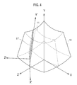
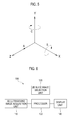
- selecting a 2D slice image 11' shown in FIG. 4 can be accomplished through the following procedure. First, the operator moves the reference plane 11 on the Z-axis toward an arrow A, as shown in FIG. 5 , by using the ref/slice button 1. Then, the operator rotates the reference plane 11 centering on the X-axis toward an arrow B, as shown in FIG. 5 , by using the X-rotation button 2. Lastly, the operator rotates the reference plane 11 centering on the Y-axis toward an arrow C, as shown in FIG. 5 , by using the Y-rotation button 3. Thereafter, it becomes possible to obtain the selected 2D slice image 11' transited from the reference plane 11 according to the aforementioned procedure.
- the ultrasound system comprises: a 3D ultrasound image acquisition unit configured to acquire a 3D ultrasound image of a target object; a 2D slice image selection unit including a control volume unit, the 2D slice image selection unit being configured to be rotated and/or moved by an operator; and a processor coupled to the 3D ultrasound image acquisition unit and 2D slice image selection unit.
- At least one selection plane is formed by the control volume unit as a reference plane for selecting at least one 2D slice image from the 3D ultrasound image.
- the processor is configured to extract at least one 2D slice image corresponding to the at least one selection plane from the 3D ultrasound image.
- the 3D ultrasound image or the at least one selection plane are rotated and/or moved together with the control volume unit.
- the at least one selection plane is fixed while the control volume unit and the 3D ultrasound image are rotated and/or moved together.
- the processor matches a coordinate system of the control volume unit to a coordinate system of the 3D ultrasound image to rotate and/or move the 3D ultrasound image and the control volume unit together relative to the at least one selection plane.
- the 3D ultrasound image is fixed while the control volume unit and the at least one selection plane are rotated and/or moved together, and the processor matches a coordinate system of the control volume unit to a coordinate system of the at least one selection plane to rotate and/or move the at least one selection plane and the control volume unit together relative to the 3D ultrasound image.
- the shape of the control volume unit corresponds to the shape of the 3D ultrasound image.
- the orientation and position recognition unit includes a sensor that is configured to detect the rotation and/or movement of the control volume unit to form detection signals. Further, the processor is configured to generate the orientation and position signal of the control volume unit based on the detection signals.
- the processor includes: a matching unit configured to match the coordinate system of the control volume unit to the coordinate system of the 3D ultrasound image; an image processing unit configured to change the orientation and position of the 3D ultrasound image or the at least one selection plane corresponding to the changed orientation and position of the control volume unit based on the orientation and position signal; and a 2D slice image extraction unit configured to extract at least one 2D slice image corresponding to the at least one selection plane from the 3D ultrasound image.
- the matching unit matches the coordinate system of the control volume unit to the coordinate system of the 3D ultrasound image. If the operation button receives input data of a second operation, then the 2D slice image extraction unit extracts the at least one 2D slice image corresponding to the at least one selection plane from the 3D ultrasound image.
- the method of selecting a 2D slice image from a 3D ultrasound image comprises the following steps : a) acquiring a 3D ultrasound image of a target object; b) matching a coordinate system of the 3D ultrasound image to a coordinate system of a control volume unit configured to be moved and/or rotated by an operator, wherein at least one selection plane is formed by the control volume unit as a reference plane for selecting at least one 2D slice image from the 3D ultrasound image; c) detecting orientation and position of the control volume unit; d) rotating and/or moving the 3D ultrasound image or the at least one selection plane together with the control volume unit; and e) extracting at least one 2D slice image corresponding to the at least one selection plane from the 3D ultrasound image.
- the at least one selection plane is fixed while the control volume unit and the 3D ultrasound image are rotated and/or moved together. Otherwise, the 3D ultrasound image is fixed while the control volume unit and the at least one selection plane are rotated and/or moved together.
- the ultrasound system 100 comprises a three-dimensional (3D) ultrasound image acquisition unit 110, a 2D slice image selection unit 120, a processor 130 and a display unit 140.
- 3D three-dimensional
- the 3D ultrasound image acquisition unit 110 is configured to transmit ultrasound signals to a target object and receive reflected ultrasound signals, i.e., ultrasound echo signals, from the target object to acquire ultrasound data thereof.
- reflected ultrasound signals i.e., ultrasound echo signals
- the 3D ultrasound image acquisition unit 110 comprises a transmit signal formation unit 111, an ultrasound probe 112 having a plurality of transducer elements (not shown), a beam former 113, an ultrasound data formation unit 114, a volume data formation unit 115 and an image formation unit 116.
- the transmit signal formation unit 111 is configured to form transmit signals in consideration of positions and focusing points of the transducer elements.
- the transmit signal formation unit 111 is configured to form the transmit signals sequentially and repeatedly.
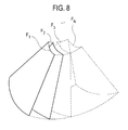
- the transmit signal formation unit 111 is configured to form the transmit signals for obtaining image frames F i (1 ⁇ i ⁇ N, N being an integer) as shown in FIG. 8 .
- the image frames F; (1 ⁇ i ⁇ N) are represented in the form of a fan-shaped image frame, although they are not limited thereto.
- the ultrasound probe 112 In response to the transmit signals from the transmit signal formation unit 111, the ultrasound probe 112 is configured to convert the transmit signals into corresponding ultrasound signals and transmit them to the target object. The ultrasound probe 112 is further configured to receive ultrasound echo signals reflected from the target object to form receive signals. The receive signals can be analog signals. The ultrasound probe 112 is configured to transmit the ultrasound signals and receive the ultrasound echo signals to form the receive signals in response to the transmit signals from the transmit signal formation unit 111. In an exemplary embodiment, the ultrasound probe 112 includes at least one of a 3D mechanical probe, a 2D array probe and the like.
- the beam former 113 is configured to convert the receive signals from analog to digital to form digital signals corresponding thereto.
- the beam former 113 is further configured to receive-focus the digital signals in consideration of the positions and focusing points of the transducer elements in the ultrasound probe 112 to form a receive-focus beam.
- the ultrasound data formation unit 114 is configured to form ultrasound data based on the receive-focus beam from the beam former 113.
- the ultrasound data formation unit 114 is configured to form the ultrasound data corresponding to the respective frames F i (1 ⁇ i ⁇ N) shown in FIG. 8 based on the receive-focus beam provided from the beam former 113.
- the volume data formation unit 115 is configured to form volume data 210 shown in FIG. 9 based on the ultrasound data from the ultrasound data formation unit 114.
- the volume data comprises the frames F i (1 ⁇ i ⁇ N) and include a plurality of voxels with brightness values.
- reference numbers 221 to 223 indicate cross-sections, which are crossed at right angles.
- an axial direction indicates a propagation direction of the ultrasound signals starting from the transducer elements of the ultrasound probe 112
- a lateral direction represents a scan line direction of the ultrasound signals
- an elevation direction depicts a depth direction of a 3D ultrasound image.
- the image formation unit 116 is configured to render the volume data from the volume data formation unit 115 to form a 3D ultrasound image.
- rendering of the image formation unit 116 includes ray-casting rendering, surface rendering and the like.
- the 2D slice image selection unit 120 is configured to select cross-sections, i.e., 2D slice images, of the 3D ultrasound image from the 3D ultrasound image acquisition unit 110 by the processor 130. A detailed description of the 2D slice image selection unit 120 will be made with reference to FIG. 10 .
- the 2D slice image selection unit 120 includes a control volume unit 121, an orientation and position recognition unit 122, a grip 123 and an operation button 124, which is configured to receive input data from the operator for the operations of the 2D slice image selection unit.
- the operation button 124 is provided on the grip 123 to receive input data from the operator.
- the input data includes first and second input data, the first input data containing data for matching the coordinates of the control volume unit to that of the 3D ultrasound image and the second input data containing data for selecting a final 2D slice image.
- the control volume unit 121 is positioned on the Cartesian coordinate system with an a-axis, a b-axis and a c-axis, which are crossed at right angles.
- a reference numeral 121a represents a selection plane to select a 2D slice image from the 3D ultrasound image, wherein at least one selection plane is formed by the control volume unit as a reference plane to select at least one 2D slice image from the 3D ultrasound image.
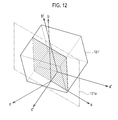
- the orientation and position of the control volume unit 121 is transited to that of a control volume unit 121' as shown in FIG. 12 . Since the orientation and position of the selection plane 121 a is fixed on the Cartesian coordinate system, the relative coordinate system of the selection plane 121a to the 3D ultrasound image 121 can be changed according to the operator's operation.
- control volume unit 121 has the shape of, for example, a rectangular solid.
- control volume unit 121 has a fan shape similar to a shape of the 3D ultrasound image, which has curved top and bottom portions. With the fan shape, the operator can intuitively match the 3D ultrasound image to the control volume unit 121.
- the orientation and position recognition unit 122 is mounted within the control volume unit 121 to recognize the orientation and position thereof.
- the processor 130 is connected to the 3D ultrasound image acquisition unit 110 and the 2D slice image selection unit 120, and the orientation and position recognition unit 122 includes a sensor (not shown) configured to detect the rotation and/or movement of the control volume unit 121 to form detection signals corresponding to the rotation and/or movement thereof.
- the processor 130 forms orientation and position signals for determining the orientation and/or position of the control volume unit 121 based on the detection signals from the sensor.
- the sensor comprises a device that detects the rotation and/or movement of the control volume unit 121.
- the sensor includes an inertial sensor, a gyro sensor, an acceleration sensor and the like.
- the processor 130 includes a micro controller unit (MCU) to form the orientation and position signals for determining the orientation and/or position of the control volume unit 121 based on the detection signals from the sensor.
- MCU micro controller unit
- the grip 123 has a shape of a stick that is projected from one surface of the control volume unit 121. Such a shape allows the operator to seize the grip 123 and change the orientation and/or position of the control volume unit 121 of 2D slice image selection unit 120.
- the processor 130 is connected to the 2D slice image selection unit 120 through wireless communication channels.
- the processor 130 is configured to match the coordinate system of the 3D ultrasound image from the 3D ultrasound image acquisition unit 110 to that of the control volume unit 121.
- the processor 130 is configured to extract a slice corresponding to the selection plane 121a from the 3D ultrasound image. A detailed description of the processor 130 will be made with reference to FIG. 13 .
- the processor 130 includes a matching unit 131, an image processing unit 132 and a 2D slice image extraction unit 133.
- the matching unit 131 is configured to match the coordinate system of the control volume unit 121 to that of the 3D ultrasound image in response to first input data from the 2D slice image selection unit 120.
- the image processing unit 132 In response to an orientation and position signal from the 2D slice image selection unit 120, the image processing unit 132 is configured to transit the orientation and position of the 3D ultrasound image (i.e., moving and rotating of the 3D ultrasound image) to correspond them to the orientation and position of the control volume unit 121, which are changed according to the orientation and position signal. For example, as shown in FIG. 12 , the image processing unit 132 matches the a'-, b'- and c'-axes of the control volume unit 121' to the X-, Y- and Z-axes of the 3D ultrasound image 10 of FIG. 4 , in response to the orientation and position signal. This is so that the orientation and position of the 3D ultrasound image is transited.
- the orientation and position of the 3D ultrasound image is transited.
- the coordinate system of the selection plane 121a corresponds to the coordinate system of the slice of the 2D slice image 11' to be displayed, as shown in FIG. 4 .
- the operator selects any one 2D slice image from the 3D ultrasound image by rotating and moving the control volume unit 121.
- the operation button 124 is provided on the grip 123 to activate operations.
- the operations include a first operation defined as the first input data and a second operation defined as the second input data.
- the matching unit 131 matches the coordinate system of the control volume unit 121 to that of the 3D ultrasound image 10.
- the 2D slice image extraction unit 133 extracts a 2D slice image on a slice corresponding to the fixed selection plane 121 a from the 3D ultrasound image 10.
- the display unit 140 is configured to display the 3D ultrasound image from the 3D ultrasound image acquisition unit 110. Further, the display unit 140 is configured to display the selected 2D slice image from the 3D ultrasound image.
- FIG. 14 there is shown a flow chart illustrating a process of selecting the 2D slice image from the 3D ultrasound image using the 2D slice image selection unit in accordance with an embodiment of the present disclosure.
- the 3D ultrasound image acquisition unit 110 transmit ultrasound signals to a target object and receive ultrasound echo signals reflected therefrom to acquire a 3D ultrasound image of the target object (S102).
- the matching unit 131 of the processor 130 matches the coordinate system of the control volume unit 121 to that of the 3D ultrasound image (S106).
- the 2D slice image extraction unit 133 extracts a first 2D slice image corresponding to the selection plane 121a from the 3D ultrasound image of which the coordinate system is matched to that of the control volume unit 121 (S108).
- the display unit 140 displays the matched 3D ultrasound image and the first 2D slice image (S110).
- the processor 130 decides whether or not the operator rotates and/or moves the control volume unit 121 due to the detection signals from the orientation and position recognition unit 122 (S 112). If it is determined that the control volume unit 121 is moved and/or rotated, then the processor 130 forms an orientation and position signal, which represents the amount of rotation and/or movement of the control volume unit 121 (S114). Otherwise, if it is determined that the control volume unit 121 is not moved and/or rotated, then the processor 130 do not form the orientation and position signal.
- the image processing unit 132 transits the orientation and position of the 3D ultrasound image to the changed orientation and position of the control volume unit 121 (S116).
- the 2D slice image extraction unit 133 extracts a final 2D slice image corresponding to the selection plane 121a from the transited 3D ultrasound image (S120). Thereafter, the display unit 140 displays the final 2D slice image from the transited 3D ultrasound image (S122).
- the matching the control volume unit 121 to the 3D ultrasound image 10 is described in the exemplary embodiment, it is possible that the coordinate system of the 3D ultrasound image 10 shown in FIG. 4 is fixed and the changed coordinate system of the control volume unit 121, i.e., a'-, b'- and c'-axes, can be matched to the coordinate system of the selected plane corresponding to the slice of the 2D slice image 11' to be displayed, i.e., X'-, Y'- and Z'-axes.
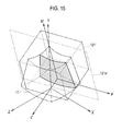
- FIG. 15 is a schematic view showing a slice selecting process to acquire a 2D slice image at an arbitrary slice according to another embodiment of the present disclosure.
- the orientation and position of the control volume unit 121 and those of the 3D ultrasound image 10 are changed relative to the selection plane 121a.
- the coordinate system of the 3D ultrasound image 10 with X-axis, Y-axis and Z-axis is fixed, while the control volume unit 121' and selection plane 121a' can be moved or rotated relative to the 3D ultrasound image with coordinates a'-axis, b'-axis and c'-axis, which represents the changed orientation and position of the control volume unit 121, as shown in FIG. 15 .
- the elements such as the matching unit can be removed since the selection plane moves and rotates with the control volume unit together. Further, the 3D ultrasound image is fixed and a 2D slice image on a slice corresponding to the selection plane 121a' can be extracted therefrom.
- the processor 130 in response to the orientation and position signal, transits the orientation and position of the selection plane 121 a' as shown in FIG. 15 .
- the process to selecting a 2D slice image from the 3D ultrasound image is slightly changed.
- the image processing unit 132 in response to the orientation and position signal, transits the orientation and position of the selection plane 121a to the changed orientation and position of the control volume unit 121 (S116').
- the 2D slice image extraction unit 133 extracts a final 2D slice image on a slice corresponding to the transited selection plane 120a' from the 3D ultrasound image (S120').
- the operator can change the orientation and position of the 3D ultrasound image by changing the orientation or position of the control volume unit.
- the operator can easily select a slice to be displayed by using the control volume unit without performing any complex button operation.
Landscapes
- Health & Medical Sciences (AREA)
- Life Sciences & Earth Sciences (AREA)
- Engineering & Computer Science (AREA)
- Physics & Mathematics (AREA)
- Animal Behavior & Ethology (AREA)
- Medical Informatics (AREA)
- Veterinary Medicine (AREA)
- Public Health (AREA)
- General Health & Medical Sciences (AREA)
- Biophysics (AREA)
- Nuclear Medicine, Radiotherapy & Molecular Imaging (AREA)
- Pathology (AREA)
- Radiology & Medical Imaging (AREA)
- Biomedical Technology (AREA)
- Heart & Thoracic Surgery (AREA)
- Surgery (AREA)
- Molecular Biology (AREA)
- Radar, Positioning & Navigation (AREA)
- Remote Sensing (AREA)
- Acoustics & Sound (AREA)
- Computer Networks & Wireless Communication (AREA)
- General Physics & Mathematics (AREA)
- Computer Graphics (AREA)
- General Engineering & Computer Science (AREA)
- Computer Vision & Pattern Recognition (AREA)
- Ultra Sonic Daignosis Equipment (AREA)
Applications Claiming Priority (2)
| Application Number | Priority Date | Filing Date | Title |
|---|---|---|---|
| KR20090124913 | 2009-12-15 | ||
| KR20100121158A KR101183767B1 (ko) | 2009-12-15 | 2010-12-01 | 삼차원 초음파 이미지로부터 이차원 슬라이스 이미지를 선택하는 초음파 시스템 및 그 방법 |
Publications (1)
| Publication Number | Publication Date |
|---|---|
| EP2335596A1 true EP2335596A1 (de) | 2011-06-22 |
Family
ID=43759753
Family Applications (1)
| Application Number | Title | Priority Date | Filing Date |
|---|---|---|---|
| EP20100194835 Withdrawn EP2335596A1 (de) | 2009-12-15 | 2010-12-14 | Ultraschallsystem und Verfahren zur Auswahl eines Schnittbildes aus einem dreidimensionalen Ultraschallbild |
Country Status (3)
| Country | Link |
|---|---|
| US (1) | US20110144499A1 (de) |
| EP (1) | EP2335596A1 (de) |
| JP (1) | JP2011125708A (de) |
Cited By (3)
| Publication number | Priority date | Publication date | Assignee | Title |
|---|---|---|---|---|
| EP3015073A1 (de) * | 2014-10-31 | 2016-05-04 | Samsung Medison Co., Ltd. | Ultraschallbildgebungsvorrichtung und verfahren zum betrieb davon |
| EP3020337A1 (de) * | 2014-11-11 | 2016-05-18 | Samsung Medison Co., Ltd. | Ultraschalldiagnosevorrichtung, betriebsverfahren dafür und computerlesbares aufzeichnungsmedium |
| WO2016156481A1 (en) | 2015-03-31 | 2016-10-06 | Koninklijke Philips N.V. | Ultrasound imaging apparatus |
Families Citing this family (8)
| Publication number | Priority date | Publication date | Assignee | Title |
|---|---|---|---|---|
| US8891881B2 (en) | 2012-01-25 | 2014-11-18 | General Electric Company | System and method for identifying an optimal image frame for ultrasound imaging |
| KR101386102B1 (ko) * | 2012-03-09 | 2014-04-16 | 삼성메디슨 주식회사 | 초음파 영상 제공 방법 및 그를 위한 초음파 장치 |
| WO2014123395A1 (en) | 2013-02-08 | 2014-08-14 | Ewoosoft Co., Ltd. | Image display to display 3d image and sectional images |
| KR102245202B1 (ko) * | 2014-03-17 | 2021-04-28 | 삼성메디슨 주식회사 | 단면 선택 라인의 방향 및 위치 중 적어도 하나를 소정의 패턴에 따라 변경하기 위한 방법 및 장치 |
| KR101790436B1 (ko) | 2016-04-15 | 2017-10-26 | 이화여자대학교 산학협력단 | 의료 영상 처리 방법 및 의료 영상 처리 장치 |
| EP3469553A1 (de) * | 2016-06-10 | 2019-04-17 | Koninklijke Philips N.V. | Systeme und verfahren zur erzeugung von b-modus-bildern aus 3d-ultraschalldaten |
| JP2018068494A (ja) * | 2016-10-26 | 2018-05-10 | 株式会社日立製作所 | 超音波画像処理装置及びプログラム |
| KR20180072358A (ko) * | 2016-12-21 | 2018-06-29 | 삼성메디슨 주식회사 | 초음파 진단 장치 및 초음파 진단 장치 제어 방법 |
Citations (2)
| Publication number | Priority date | Publication date | Assignee | Title |
|---|---|---|---|---|
| EP1550883A2 (de) * | 2003-12-31 | 2005-07-06 | Medison Co., Ltd. | Vorrichtung und Verfahren zum Abbilden von Schnittebenen eines Objekts unter Benutzung von 3D Ultraschalldatensätzen |
| EP1757229A1 (de) * | 2004-05-14 | 2007-02-28 | Matsushita Electric Industrial Co., Ltd. | Ultraschalldiagnosegerät und ultraschallbild-darstellungsverfahren |
-
2010
- 2010-12-14 EP EP20100194835 patent/EP2335596A1/de not_active Withdrawn
- 2010-12-15 JP JP2010279613A patent/JP2011125708A/ja not_active Withdrawn
- 2010-12-15 US US12/968,782 patent/US20110144499A1/en not_active Abandoned
Patent Citations (2)
| Publication number | Priority date | Publication date | Assignee | Title |
|---|---|---|---|---|
| EP1550883A2 (de) * | 2003-12-31 | 2005-07-06 | Medison Co., Ltd. | Vorrichtung und Verfahren zum Abbilden von Schnittebenen eines Objekts unter Benutzung von 3D Ultraschalldatensätzen |
| EP1757229A1 (de) * | 2004-05-14 | 2007-02-28 | Matsushita Electric Industrial Co., Ltd. | Ultraschalldiagnosegerät und ultraschallbild-darstellungsverfahren |
Cited By (6)
| Publication number | Priority date | Publication date | Assignee | Title |
|---|---|---|---|---|
| EP3015073A1 (de) * | 2014-10-31 | 2016-05-04 | Samsung Medison Co., Ltd. | Ultraschallbildgebungsvorrichtung und verfahren zum betrieb davon |
| KR20160051160A (ko) * | 2014-10-31 | 2016-05-11 | 삼성메디슨 주식회사 | 초음파 영상 장치 및 그 동작 방법 |
| EP3020337A1 (de) * | 2014-11-11 | 2016-05-18 | Samsung Medison Co., Ltd. | Ultraschalldiagnosevorrichtung, betriebsverfahren dafür und computerlesbares aufzeichnungsmedium |
| KR20160056164A (ko) * | 2014-11-11 | 2016-05-19 | 삼성메디슨 주식회사 | 초음파 진단장치, 그에 따른 초음파 진단 장치의 동작 방법 및 그에 따른 컴퓨터 판독 가능한 저장매체 |
| US10383599B2 (en) | 2014-11-11 | 2019-08-20 | Samsung Medison Co., Ltd. | Ultrasound diagnostic apparatus, operating method thereof, and computer-readable recording medium |
| WO2016156481A1 (en) | 2015-03-31 | 2016-10-06 | Koninklijke Philips N.V. | Ultrasound imaging apparatus |
Also Published As
| Publication number | Publication date |
|---|---|
| US20110144499A1 (en) | 2011-06-16 |
| JP2011125708A (ja) | 2011-06-30 |
Similar Documents
| Publication | Publication Date | Title |
|---|---|---|
| EP2335596A1 (de) | Ultraschallsystem und Verfahren zur Auswahl eines Schnittbildes aus einem dreidimensionalen Ultraschallbild | |
| CN100595605C (zh) | 用图标描述相互平面方向的双平面超声成像 | |
| JP4732034B2 (ja) | 超音波システムの表示を制御するための方法及び装置 | |
| JP4473729B2 (ja) | 時間インタリーブデータの取得によるバイプレイン超音波描出処理 | |
| JP5537171B2 (ja) | 超音波撮影装置、画像処理装置、画像処理方法及び画像処理プログラム | |
| CN103908298B (zh) | 超声成像系统和方法 | |
| EP3600063B1 (de) | Volumengerenderte ultraschallbildgebung | |
| US20140128739A1 (en) | Ultrasound imaging system and method | |
| EP2610635A2 (de) | Erstellung von spektralen Doppler Bildern, die mindestens zwei Probenvolumen entsprechen | |
| KR20110064842A (ko) | 2차원 초음파 영상과 3차원 초음파 영상의 합성영상을 제공하는 초음파 시스템 및 방법 | |
| CN103037773A (zh) | 个体双平面图像的显示和输出 | |
| JP4865575B2 (ja) | 超音波診断装置 | |
| EP3451932B1 (de) | Ultraschallbildgebungssystem mit vereinfachten 3d-bildgebungssteuerungen | |
| JP5670253B2 (ja) | 超音波診断装置 | |
| WO2010032155A1 (en) | 3-d ultrasound imaging with volume data processing | |
| JP3410404B2 (ja) | 超音波診断装置 | |
| KR101183767B1 (ko) | 삼차원 초음파 이미지로부터 이차원 슬라이스 이미지를 선택하는 초음파 시스템 및 그 방법 | |
| US7946989B2 (en) | Ultrasonic diagnosing apparatus and ultrasonic image display method | |
| JP2000296129A (ja) | 超音波診断装置 | |
| JP2009011449A (ja) | 超音波診断装置 | |
| JP2004130134A (ja) | バイプレーン超音波撮像法 | |
| US20250152133A1 (en) | Ultrasound diagnostic support device, ultrasound diagnostic device, ultrasound diagnostic support method, and computer-readable non-transitory recording medium storing program | |
| US20250331821A1 (en) | System and method for displaying a visual indicator that indicates a movement direction of an ultrasound probe relative to an ultrasound image | |
| KR101487688B1 (ko) | 단면의 위치를 가이드하기 위한 내비게이터를 제공하는 초음파 시스템 및 방법 | |
| JP2026028510A (ja) | 情報処理装置及び情報処理方法 |
Legal Events
| Date | Code | Title | Description |
|---|---|---|---|
| PUAI | Public reference made under article 153(3) epc to a published international application that has entered the european phase |
Free format text: ORIGINAL CODE: 0009012 |
|
| AK | Designated contracting states |
Kind code of ref document: A1 Designated state(s): AL AT BE BG CH CY CZ DE DK EE ES FI FR GB GR HR HU IE IS IT LI LT LU LV MC MK MT NL NO PL PT RO RS SE SI SK SM TR |
|
| AX | Request for extension of the european patent |
Extension state: BA ME |
|
| 17P | Request for examination filed |
Effective date: 20111215 |
|
| RIC1 | Information provided on ipc code assigned before grant |
Ipc: A61B 8/14 20060101AFI20131107BHEP Ipc: G01S 15/89 20060101ALI20131107BHEP |
|
| STAA | Information on the status of an ep patent application or granted ep patent |
Free format text: STATUS: THE APPLICATION HAS BEEN WITHDRAWN |
|
| 18W | Application withdrawn |
Effective date: 20140113 |