EP2335629B1 - Outil à utiliser avec un ancrage d'os, en particulier pour la chirurgie de la colonne vertébrale - Google Patents
Outil à utiliser avec un ancrage d'os, en particulier pour la chirurgie de la colonne vertébrale Download PDFInfo
- Publication number
- EP2335629B1 EP2335629B1 EP11155454.9A EP11155454A EP2335629B1 EP 2335629 B1 EP2335629 B1 EP 2335629B1 EP 11155454 A EP11155454 A EP 11155454A EP 2335629 B1 EP2335629 B1 EP 2335629B1
- Authority
- EP
- European Patent Office
- Prior art keywords
- tool
- gear unit
- torque
- counter
- bone anchor
- Prior art date
- Legal status (The legal status is an assumption and is not a legal conclusion. Google has not performed a legal analysis and makes no representation as to the accuracy of the status listed.)
- Not-in-force
Links
Images




Classifications
-
- A—HUMAN NECESSITIES
- A61—MEDICAL OR VETERINARY SCIENCE; HYGIENE
- A61B—DIAGNOSIS; SURGERY; IDENTIFICATION
- A61B17/00—Surgical instruments, devices or methods
- A61B17/56—Surgical instruments or methods for treatment of bones or joints; Devices specially adapted therefor
- A61B17/58—Surgical instruments or methods for treatment of bones or joints; Devices specially adapted therefor for osteosynthesis, e.g. bone plates, screws or setting implements
- A61B17/68—Internal fixation devices, including fasteners and spinal fixators, even if a part thereof projects from the skin
- A61B17/70—Spinal positioners or stabilisers, e.g. stabilisers comprising fluid filler in an implant
- A61B17/7074—Tools specially adapted for spinal fixation operations other than for bone removal or filler handling
- A61B17/7091—Tools specially adapted for spinal fixation operations other than for bone removal or filler handling for applying, tightening or removing longitudinal element-to-bone anchor locking elements, e.g. caps, set screws, nuts or wedges
-
- A—HUMAN NECESSITIES
- A61—MEDICAL OR VETERINARY SCIENCE; HYGIENE
- A61B—DIAGNOSIS; SURGERY; IDENTIFICATION
- A61B17/00—Surgical instruments, devices or methods
- A61B17/56—Surgical instruments or methods for treatment of bones or joints; Devices specially adapted therefor
- A61B17/58—Surgical instruments or methods for treatment of bones or joints; Devices specially adapted therefor for osteosynthesis, e.g. bone plates, screws or setting implements
- A61B17/68—Internal fixation devices, including fasteners and spinal fixators, even if a part thereof projects from the skin
- A61B17/70—Spinal positioners or stabilisers, e.g. stabilisers comprising fluid filler in an implant
- A61B17/7074—Tools specially adapted for spinal fixation operations other than for bone removal or filler handling
- A61B17/7076—Tools specially adapted for spinal fixation operations other than for bone removal or filler handling for driving, positioning or assembling spinal clamps or bone anchors specially adapted for spinal fixation
- A61B17/7082—Tools specially adapted for spinal fixation operations other than for bone removal or filler handling for driving, positioning or assembling spinal clamps or bone anchors specially adapted for spinal fixation for driving, i.e. rotating, screws or screw parts specially adapted for spinal fixation, e.g. for driving polyaxial or tulip-headed screws
-
- A—HUMAN NECESSITIES
- A61—MEDICAL OR VETERINARY SCIENCE; HYGIENE
- A61B—DIAGNOSIS; SURGERY; IDENTIFICATION
- A61B17/00—Surgical instruments, devices or methods
- A61B17/56—Surgical instruments or methods for treatment of bones or joints; Devices specially adapted therefor
- A61B17/58—Surgical instruments or methods for treatment of bones or joints; Devices specially adapted therefor for osteosynthesis, e.g. bone plates, screws or setting implements
- A61B17/88—Osteosynthesis instruments; Methods or means for implanting or extracting internal or external fixation devices
- A61B17/8875—Screwdrivers, spanners or wrenches
-
- A—HUMAN NECESSITIES
- A61—MEDICAL OR VETERINARY SCIENCE; HYGIENE
- A61B—DIAGNOSIS; SURGERY; IDENTIFICATION
- A61B90/00—Instruments, implements or accessories specially adapted for surgery or diagnosis and not covered by any of the groups A61B1/00 - A61B50/00, e.g. for luxation treatment or for protecting wound edges
- A61B90/03—Automatic limiting or abutting means, e.g. for safety
- A61B2090/031—Automatic limiting or abutting means, e.g. for safety torque limiting
-
- A—HUMAN NECESSITIES
- A61—MEDICAL OR VETERINARY SCIENCE; HYGIENE
- A61B—DIAGNOSIS; SURGERY; IDENTIFICATION
- A61B90/00—Instruments, implements or accessories specially adapted for surgery or diagnosis and not covered by any of the groups A61B1/00 - A61B50/00, e.g. for luxation treatment or for protecting wound edges
- A61B90/06—Measuring instruments not otherwise provided for
- A61B2090/064—Measuring instruments not otherwise provided for for measuring force, pressure or mechanical tension
-
- B—PERFORMING OPERATIONS; TRANSPORTING
- B25—HAND TOOLS; PORTABLE POWER-DRIVEN TOOLS; MANIPULATORS
- B25B—TOOLS OR BENCH DEVICES NOT OTHERWISE PROVIDED FOR, FOR FASTENING, CONNECTING, DISENGAGING, OR HOLDING
- B25B17/00—Hand-driven gear-operated wrenches or screwdrivers
Definitions
- the invention relates to a tool for use with a bone anchor, wherein the bone anchor has an anchoring section and a receiving part for receiving a rod to be connected to the anchoring section and a locking element.
- the tool is particularly applicable in spinal surgery, for example for the fixation of a rod to pedicle screws.
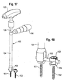
- a known tool 100 is shown in Fig. 17 and 18 in connection with polyaxial screws 101, 102 which are connected via a rod 103.
- the tool 100 comprises a counter-holding portion 104 with a handle 105 and a screw driver portion 106 which is rotatable with respect to the counter-holding portion 104 and which also comprises a handle 107.
- the screw driver portion 106 has a tip portion (not shown) which engages a locking screw 108 of the polyaxial screw for fixation of the rod 103 within the receiving part 109.
- the counter-holding portion 104 engages the receiving part 109 and holds the receiving part during tightening of the locking screw 108.
- the tightening torque which is necessary for finally tightening the locking screw 108 typically is in the range of approximately 7 to 15 Nm.
- the counter-holding portion is advantageous in particular for counter-holding such high tightening torques.
- the known tool since the counter-holding portion acts at least partially onto the rod, the known tool is not suitable for flexible rods, for example for rods made of an elastomer material such as PCU, since the loads would lead to deformations which may damage the rod. Further, the sensitive handling with two hands is difficult when applying high tightening torques.
- a tool which has a counter-holding portion which engages the receiving portion of a bone anchor in a positive fit manner is known from EP 1 726 264 .
- US-Patent 7,296,500 shows a system for applying torque to a fastener, with a torque transfer mechanism and an anti-torque component.
- the system comprises a gear and a display member with twistable elements which displays the applied torque.
- the tool has the advantage that the tightening torque which has to be applied manually by the surgeon is considerably reduced. Therefore, the manually applied fastening torque is small and tightening of the locking screw can be performed smoothly.
- the tip portion of the screw driver portion of the tool may be exchangeable. There-fore, a suitable tip portion can be selected and the tool can be used for different kinds of locking elements.
- the applied fastening torque may be limited by either observing a display indicating the applied torque and manually stopping the application of torque or by using a preset torque adapter which can be mounted together with the gear unit.
- the tool comprises a screw driver portion which includes a drive shaft 1 as schematically shown by the dashed live in Fig. 1 and a driven shaft 2 as shown in Fig. 3 .
- the drive shaft 1 has a handle 3 at its free end projecting outside a housing 4.
- the drive shaft 1 and the driven shaft 2 enclose an angle of 90° and are connected by a reduction gear unit 5 which will be explained more in detail below.
- the tool further comprises a counter-holding portion 6 which is fixedly connected to the housing 4 so that the drive shaft 2 is rotatable with respect to the counter-holding portion 6.
- the housing 4 At its free end opposite to the counter-holding portion 6 the housing 4 comprises a handle 7 for holding the tool.
- the tool further has a display member 8 which may include visual marks 9 for indicating the applied torque.
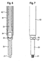
- the driven shaft 2 has, as can be seen in Fig. 3, 4 , 6 and 7 a tip portion 20 with an engagement portion 21 for engagement with a locking element of a bone anchor.
- a locking element can be, for example, a set screw 108 (shown in Fig. 16 ) of a receiving part 109 of a polyaxial bone screw.
- the engagement portion 21 can have a hexagon shape or a flathead, crosshead, square, hexsocket or torx shape or any other shape adapted to the respective engagement portion of the locking element.
- the tip portion is connected via a plug connection member 22 to a main shaft portion 23 of the driven shaft 2.
- the main shaft portion 23 has at its end facing the tip portion 20 a section 24 with an enlarged outer diameter and a recess for inserting the plug connection member 22.
- the tip portion has at its end facing the main shaft portion a recess for inserting a portion of the plug connection member 22.
- the plug connection member 22 can have a resilient portion 25 which allows the releasable holding of the tip portion 20 in the main shaft portion 23.
- the tip portion 20 and the main shaft portion 23 are connected in a positive fit manner, such as, for example, shown in Fig. 7 by means of circumferentially projecting portions 26 which engage in circumferentially arranged recesses 27 at the corresponding other part, respectively.
- a plurality of tip portions 20 may be provided with different engagement portions 21 which can be interchangeably connected to the main shaft portion 23.
- the main shaft portion 23 comprises an engagement portion 28 to be connected with the gear unit 5.
- the gear unit 5 includes a worm drive having a worm 51 connected to the drive shaft 1 and a worm wheel 52.
- the worm wheel 52 also is provided with an engagement portion 53 to be engaged with the engagement portion 28 of the main shaft portion 23.
- the gear transmission ratio is for the application in spinal surgery around 3:1 1 or 10:1.
- the worm drive is advantageous to transmit higher torques.
- a common advantage of a worm drive is that the direction of transmission from the drive shaft to the driven shaft is not reversible. In surgery this has the advantage that the final tightening of the locking element can be performed exactly.
- the display member 8 comprises a tube portion 81 which is fixed at its lower end to the main shaft portion 23 of the driven shaft 2 so that it rotates with the driven shaft 2.
- the display member 8 At its end facing away from the tip portion 20 the display member 8 comprises a lower ring-shaped portion 82 with an enlarged diameter which carries a first visual mark 9a at its outer side.
- the visual mark 9a can be of any type including bars, engravings etc. It serves for indicating a predefined tightening torque.
- the display member 8 further comprises an upper ring-shaped portion 83 which is connected to the worm wheel 52 and therefore to the main shaft portion 23.
- the lower ring-shaped portion 82 and the upper ring shaped portion are rotatable against each other. Between the two ring-shaped portions, a ring shaped plate member for facilitating gliding may be provided.
- the upper and lower ring-shaped portions have second visual marks 9b which indicate zero position.
- the housing 4 comprises a recess 41 to allow inspection of the visual marks indicating the applied torque.
- the handle 7 may be fixedly attached to the housing 4, for example by screwing as shown in Fig. 13 .
- the housing 4 further has on its end opposite to the handle 7 a projection with fixation means, for example of the type of a thread, to connect the housing 4 to the counter-holding portion 6.
- the counter-holding portion 6 has on its end facing the housing connection means 61 for connecting it fixedly to the housing 4.
- the counter-holding portion 6 further includes a main tube portion 62 shown in Fig. 3 the diameter of which is such that the driven shaft 2 and the tube portion 81 can be arranged and freely rotate therein.
- the counter-holding portion comprises an end section 63 as shown in Fig. 3 and 5 which is hollow so that the tip portion 20 extends through the end section 63.
- the end section 63 has at its free end an engagement portion 64 engaging the receiving part 109 of the bone anchor.
- the engagement section 64 has a square or rectangular inner contour which is adapted to the outer contour of the receiving portion 109.
- the receiving portion 109 has two opposed flat outer surfaces 110 as shown for example in Fig. 5 and the engagement section 64 has corresponding inner flat surfaces 65 as shown in Figs. 8 and 9 .
- the engagement portion 64 has on the other two sides two recesses 66 where the rod 103 can be guided through.
- the end section 63 further has on the side which includes the flat surfaces two recesses 67 which allow visualisation of the inserted tip portion 20.
- the end section is fixedly connected to the end tube portion 62.
- it can also be releasably attached thereto so as to allow fixation of different end section 63 with engagement portion 64 adapted to the shape and size of the receiving part.
- the engagement portion 64 can have any shape which provides for a positive fit connection with the receiving part 109 without acting onto the rod 103.
- FIG. 14a schematically shows bone anchor which is in this example a polyaxial bone screw 101 comprising a receiving part 109 and set screw 108 for fixation of the rod (not shown) in the receiving part.
- the bone anchor 101 is inserted into the bone, then the rod 103 and thereafter the set screw 108 is inserted.
- the counter-holding portion 6 is fixed with the engagement portion 64 at the receiving part as shown in Fig. 14b ).
- the driven shaft including the tip portion 20 is inserted.
- the housing 4 with the reduction gear unit and the handles is mounted.
- the upper ring-shaped portion 83 rotates with respect to the lower ring-shaped portion 82 while the main shaft portion is twisted.
- a predefined tightening torque is applied. Because of the gear unit, final tightening of the set screw is possible with low tightening torque to be manually applied.
- the tool may be preassembled or assembled before or during surgery.
- the visual mark 9a can be applied when calibrating the tool.
- the angle of 90° between drive shaft and driven shaft provides a convenient handling.
- the torque flow is such that the torque is transmitted from the driven shaft to the set screw and are redirected by the end section 63 of the counter-holding portion. Therefore, no forces are conducted via the rod back to the receiving portion which could loosen the anchoring section in the bone.
- a preset torque adapter 90 is provided which limits the applicable torque to a specific predefined value.
- the preset torque adapter 90 is arranged in a housing 4' which can be releasably connected to the main shaft portion 23 of the driven shaft.
- the preset torque adapter 90 has a shaft portion 91 which can be coupled to the main shaft portion 23 to transfer the torque.
- the preset torque adapter further has recess 92 on the side opposite to the shaft portion 91 in which a shaft 53' engages which is fixidly connected to the worm wheel 52 of the gear unit 5.
- the recess 92 may be square recess, hexagon recess or any other recess by means of which torque can be transferred from the shaft portion 53' to the torque adapter 90.
- the torque adapter 90 has in its interior a clutch mechanism (not shown) which has a defined release torque.
- the clutch mechanism can be slipping clutch. If the applied torque exceeds the predefined torque the torque is no longer transferred from the shaft portion 53' via the torque adapter to the main shaft portion 23.
- the housing 4' also contains the gear unit 5. It may be closed by a closure 45 with our without an additional handle. Further, the housing 4' can be connected to the counter-holding portion 6 via a screw or a press-fit or any other connection 46.
- the whole unit including the gear unit and the torque adapter can be selectively connected instead of the housing with the gear unit and the display unit according to the previous embodiment
- the gear unit needs not to be a worm drive, it could also be realized by a planetary gear unit, in particular with coaxial drive shaft and driven shaft. Any other reduction gear unit may be used also.
- the counter-holding portion and the tip portion may be exchanged such that the counter holding portion is at the center and the tip portion of the screw driver is surrounding it.
- the counter-holding portion and the tip portion can be adapted in their shape to various shapes of receiving portions and locking elements.
Landscapes
- Health & Medical Sciences (AREA)
- Orthopedic Medicine & Surgery (AREA)
- Neurology (AREA)
- Life Sciences & Earth Sciences (AREA)
- Surgery (AREA)
- Heart & Thoracic Surgery (AREA)
- Engineering & Computer Science (AREA)
- Biomedical Technology (AREA)
- Nuclear Medicine, Radiotherapy & Molecular Imaging (AREA)
- Medical Informatics (AREA)
- Molecular Biology (AREA)
- Animal Behavior & Ethology (AREA)
- General Health & Medical Sciences (AREA)
- Public Health (AREA)
- Veterinary Medicine (AREA)
- Surgical Instruments (AREA)
- Dental Prosthetics (AREA)
Claims (13)
- Outil à utiliser avec un ancrage d'os,
l'outil comprenant
une partie (20) d'extrémité pour engager un élément (108) de verrouillage de l'ancrage d'os,
un mécanisme (1, 2) pour appliquer un couple à la partie (20) d'extrémité,
une partie (6) de contre-prise, dans laquelle la partie (20) d'extrémité peut tourner par rapport à la partie (6) de contre-prise,
dans lequel le mécanisme d'application de couple comprend une unité d'engrenage (5), et dans lequel l'outil comprend en outre un élément (8) d'affichage pour indiquer la valeur du couple appliqué, et dans lequel le mécanisme (2) comprend un élément (23) pouvant subir une torsion et l'élément (8) d'affichage indique une torsion de celui-ci,
dans lequel
l'élément (8) d'affichage comprend une première partie (82) qui est reliée à une première extrémité de l'élément (23) pouvant subir une torsion et une deuxième partie (83) en forme d'anneau qui est reliée à une deuxième extrémité de l'élément pouvant subir une torsion et dans lequel la première partie (82) et la deuxième partie (83) en forme d'anneau peuvent tourner l'une contre l'autre lorsque l'élément (23) pouvant subir une torsion est tordu, caractérisé en ce que
la première partie (82) est en forme d'anneau. - Outil de la revendication 1, dans lequel l'unité d'engrenage (5) est une unité d'engrenage réducteur.
- Outil de la revendication 2, dans lequel le rapport de démultiplication est dans la plage allant approximativement de 3:1 à 10:1.
- Outil de l'une des revendications 1 à 3, dans lequel l'unité d'engrenage (5) comprend un engrenage conique.
- Outil de l'une des revendications 1 à 4, dans lequel l'unité d'engrenage (5) comprend un entraînement à vis sans fin.
- Outil de l'une des revendications 1 à 3, dans lequel l'unité d'engrenage comprend un entraînement planétaire.
- Outil de l'une des revendications 1 à 6, dans lequel la partie (20) d'extrémité est reliée de façon amovible à un arbre entraîné de l'unité d'engrenage (5).
- Outil de la revendication 7, dans lequel une pluralité de parties (20) d'extrémité est fournie, lesquelles parties peuvent être reliées de façon interchangeable à l'arbre entraîné.
- Outil de l'une des revendications 1 à 8, dans lequel l'arbre (1) d'entraînement de l'unité d'engrenage (5) comprend une poignée (3).
- Outil de l'une des revendications 1 à 9, dans lequel la partie de contre-prise comprend une partie (64) d'engagement pour venir en prise avec la partie (109) de réception qui est construite afin de fournir une liaison par complémentarité de forme.
- Outil de la revendication 10, dans lequel la partie (64) d'engagement présente deux surfaces (65) planes opposées.
- Outil de l'une des revendications 1 à 11, dans lequel le mécanisme (2) comprend un adaptateur de couple prédéfini qui peut être sélectivement relié à la partie (20) d'extrémité.
- Kit avec un ancrage d'os comprenant une section d'ancrage à ancrer dans l'os et une partie (109) de réception pour recevoir une tige (103) et un élément (108) de verrouillage coopérant avec la partie de réception et un outil selon l'une des revendications 1 à 12.
Priority Applications (1)
| Application Number | Priority Date | Filing Date | Title |
|---|---|---|---|
| EP11155454.9A EP2335629B1 (fr) | 2009-04-07 | 2009-04-07 | Outil à utiliser avec un ancrage d'os, en particulier pour la chirurgie de la colonne vertébrale |
Applications Claiming Priority (2)
| Application Number | Priority Date | Filing Date | Title |
|---|---|---|---|
| EP11155454.9A EP2335629B1 (fr) | 2009-04-07 | 2009-04-07 | Outil à utiliser avec un ancrage d'os, en particulier pour la chirurgie de la colonne vertébrale |
| EP09005130A EP2238937B1 (fr) | 2009-04-07 | 2009-04-07 | Outil à utiliser avec un ancrage d'os, en particulier pour la chirurgie de la colonne vertébrale |
Related Parent Applications (3)
| Application Number | Title | Priority Date | Filing Date |
|---|---|---|---|
| EP09005130A Division-Into EP2238937B1 (fr) | 2009-04-07 | 2009-04-07 | Outil à utiliser avec un ancrage d'os, en particulier pour la chirurgie de la colonne vertébrale |
| EP09005130A Division EP2238937B1 (fr) | 2009-04-07 | 2009-04-07 | Outil à utiliser avec un ancrage d'os, en particulier pour la chirurgie de la colonne vertébrale |
| EP09005130.1 Division | 2009-04-07 |
Publications (2)
| Publication Number | Publication Date |
|---|---|
| EP2335629A1 EP2335629A1 (fr) | 2011-06-22 |
| EP2335629B1 true EP2335629B1 (fr) | 2014-03-26 |
Family
ID=41073439
Family Applications (3)
| Application Number | Title | Priority Date | Filing Date |
|---|---|---|---|
| EP09005130A Not-in-force EP2238937B1 (fr) | 2009-04-07 | 2009-04-07 | Outil à utiliser avec un ancrage d'os, en particulier pour la chirurgie de la colonne vertébrale |
| EP11155459A Withdrawn EP2324787A1 (fr) | 2009-04-07 | 2009-04-07 | Outil à utiliser avec un ancrage d'os, en particulier pour la chirurgie de la colonne vertébrale |
| EP11155454.9A Not-in-force EP2335629B1 (fr) | 2009-04-07 | 2009-04-07 | Outil à utiliser avec un ancrage d'os, en particulier pour la chirurgie de la colonne vertébrale |
Family Applications Before (2)
| Application Number | Title | Priority Date | Filing Date |
|---|---|---|---|
| EP09005130A Not-in-force EP2238937B1 (fr) | 2009-04-07 | 2009-04-07 | Outil à utiliser avec un ancrage d'os, en particulier pour la chirurgie de la colonne vertébrale |
| EP11155459A Withdrawn EP2324787A1 (fr) | 2009-04-07 | 2009-04-07 | Outil à utiliser avec un ancrage d'os, en particulier pour la chirurgie de la colonne vertébrale |
Country Status (7)
| Country | Link |
|---|---|
| US (2) | US9149308B2 (fr) |
| EP (3) | EP2238937B1 (fr) |
| JP (1) | JP5610820B2 (fr) |
| KR (1) | KR101501272B1 (fr) |
| CN (1) | CN101856263B (fr) |
| ES (2) | ES2393583T3 (fr) |
| TW (1) | TWI527556B (fr) |
Families Citing this family (40)
| Publication number | Priority date | Publication date | Assignee | Title |
|---|---|---|---|---|
| US7862587B2 (en) | 2004-02-27 | 2011-01-04 | Jackson Roger P | Dynamic stabilization assemblies, tool set and method |
| US20160242816A9 (en) | 2001-05-09 | 2016-08-25 | Roger P. Jackson | Dynamic spinal stabilization assembly with elastic bumpers and locking limited travel closure mechanisms |
| US11241261B2 (en) | 2005-09-30 | 2022-02-08 | Roger P Jackson | Apparatus and method for soft spinal stabilization using a tensionable cord and releasable end structure |
| US7901437B2 (en) | 2007-01-26 | 2011-03-08 | Jackson Roger P | Dynamic stabilization member with molded connection |
| US11224463B2 (en) | 2007-01-18 | 2022-01-18 | Roger P. Jackson | Dynamic stabilization connecting member with pre-tensioned flexible core member |
| US10383660B2 (en) | 2007-05-01 | 2019-08-20 | Roger P. Jackson | Soft stabilization assemblies with pretensioned cords |
| US8439922B1 (en) | 2008-02-06 | 2013-05-14 | NiVasive, Inc. | Systems and methods for holding and implanting bone anchors |
| WO2010147639A1 (fr) * | 2008-08-01 | 2010-12-23 | Jackson Roger P | Élément longitudinal de liaison avec cordons tendus gainés |
| EP2238937B1 (fr) * | 2009-04-07 | 2012-08-22 | Biedermann Technologies GmbH & Co. KG | Outil à utiliser avec un ancrage d'os, en particulier pour la chirurgie de la colonne vertébrale |
| US20150105831A1 (en) * | 2009-10-09 | 2015-04-16 | Synthes Usa, Lla | Tightening device for spine surgery |
| US8545505B2 (en) | 2010-01-15 | 2013-10-01 | Pioneer Surgical Technology, Inc. | Low friction rod persuader |
| JP2013540468A (ja) | 2010-09-08 | 2013-11-07 | ロジャー・ピー・ジャクソン | 弾性部および非弾性部を有する動的固定化部材 |
| US8696511B2 (en) * | 2010-10-29 | 2014-04-15 | Warsaw Orthopedic, Inc. | Surgical instrument with plantary gear system |
| US9198698B1 (en) | 2011-02-10 | 2015-12-01 | Nuvasive, Inc. | Minimally invasive spinal fixation system and related methods |
| GB2497782A (en) | 2011-12-20 | 2013-06-26 | Vincent Lefauconnier | Bone fixation device |
| US9554820B2 (en) | 2012-06-01 | 2017-01-31 | Covidien Lp | Ultrasonic surgical instrument |
| US9402673B2 (en) * | 2012-09-28 | 2016-08-02 | DePuy Synthes Products, Inc. | Devices and methods for breaking and retaining surgical reduction tabs |
| US20150297247A1 (en) | 2012-12-08 | 2015-10-22 | Kevin Seex | Surgical Tool |
| US10136927B1 (en) | 2013-03-15 | 2018-11-27 | Nuvasive, Inc. | Rod reduction assemblies and related methods |
| US9486256B1 (en) | 2013-03-15 | 2016-11-08 | Nuvasive, Inc. | Rod reduction assemblies and related methods |
| US10405897B2 (en) | 2014-04-08 | 2019-09-10 | Medacta International Sa | Fixing device for a surgical anchor member |
| DE102014109200A1 (de) * | 2014-07-01 | 2016-01-07 | Aesculap Ag | Medizinischer Schraubendreher, Schaft für den medizinischen Schraubendreher und Verfahren zum Einbringen von Pedikelschrauben |
| US9855087B2 (en) | 2014-08-04 | 2018-01-02 | DePuy Synthes Products, LLC | Methods and devices for spinal screw insertion |
| EP3193755B1 (fr) * | 2014-09-19 | 2022-02-09 | In Queue Innovations, LLC | Systèmes de fusion d'assemblage et d'utilisation associés |
| US9987066B2 (en) | 2014-12-15 | 2018-06-05 | Medos International Sarl | Bone anchor driver and methods |
| US11672575B2 (en) | 2015-03-11 | 2023-06-13 | Warsaw Orthopedic, Inc. | Surgical instrument and method |
| US11278325B2 (en) | 2015-03-11 | 2022-03-22 | Warsaw Orthopedic, Inc. | Surgical instrument and method |
| EP3092962B1 (fr) * | 2015-05-12 | 2017-10-04 | Biedermann Technologies GmbH & Co. KG | Instrument destiné à être utilisé avec un dispositif d'ancrage osseux polyaxial et système comprenant ledit instrument et un tel dispositif d'ancrage |
| US9974577B1 (en) | 2015-05-21 | 2018-05-22 | Nuvasive, Inc. | Methods and instruments for performing leveraged reduction during single position spine surgery |
| CN105232124A (zh) * | 2015-10-13 | 2016-01-13 | 广州聚生生物科技有限公司 | 一种徒手置钉外固定系统 |
| CN106002428A (zh) * | 2016-06-20 | 2016-10-12 | 昆山鸿福泰环保科技有限公司 | 一种新型接收内杆 |
| US10398481B2 (en) | 2016-10-03 | 2019-09-03 | Nuvasive, Inc. | Spinal fixation system |
| CN106510834B (zh) * | 2016-11-22 | 2020-05-12 | 常州华森医疗器械有限公司 | 椎弓根固定系统用安装工具 |
| US10779866B2 (en) | 2016-12-29 | 2020-09-22 | K2M, Inc. | Rod reducer assembly |
| US10433883B2 (en) * | 2017-06-27 | 2019-10-08 | Medos International Sarl | Spinal screw insertion devices and methods |
| US10463404B2 (en) | 2017-07-27 | 2019-11-05 | Warsaw Orthopedic, Inc. | Spinal implant system and method |
| US11051861B2 (en) | 2018-06-13 | 2021-07-06 | Nuvasive, Inc. | Rod reduction assemblies and related methods |
| US11229462B2 (en) | 2019-05-07 | 2022-01-25 | Warsaw Orthopedic, Inc. | Head assembly inserters |
| US11432852B1 (en) | 2021-03-22 | 2022-09-06 | Warsaw Orthopedic, Inc. | Screw shank based tissue retraction |
| CN118924410B (zh) * | 2024-10-15 | 2025-02-14 | 湖南翊元科技有限公司 | 一种骨科手术用电动扳手 |
Family Cites Families (41)
| Publication number | Priority date | Publication date | Assignee | Title |
|---|---|---|---|---|
| DE8526564U1 (de) * | 1985-09-17 | 1986-03-06 | Kreidler, Eberhard, 7204 Wurmlingen | Vorrichtung zum Antreiben eines Werkzeugs |
| US4762031A (en) * | 1986-09-05 | 1988-08-09 | Ross Bradley | Ratchet wrenches |
| US5632748A (en) * | 1993-06-14 | 1997-05-27 | Linvatec Corporation | Endosteal anchoring device for urging a ligament against a bone surface |
| EP0704281B1 (fr) * | 1994-09-27 | 1998-08-19 | Institut Straumann Ag | Clé dynamométrique chirurgicale avec indicateur de couple |
| IL128261A0 (en) * | 1999-01-27 | 1999-11-30 | Disc O Tech Medical Tech Ltd | Expandable element |
| US6272952B1 (en) * | 2000-05-10 | 2001-08-14 | Yu-Tu Hsu | Double-reversible screwdriver and wrench combination hand tool |
| US6330845B1 (en) * | 2000-05-17 | 2001-12-18 | Bristol-Myers Squibb | Wrench for an implant |
| US6634260B1 (en) * | 2000-11-02 | 2003-10-21 | Jonathan R Smith | Anchored and screw assisted wrench tool |
| US6393949B1 (en) * | 2000-12-27 | 2002-05-28 | Yen Hsing Enterprise Co., Ltd. | Ratchet screwdriver |
| JP2003019142A (ja) * | 2001-07-05 | 2003-01-21 | Robert Reed Shokai Co Ltd | 医療用ドライバー |
| DE10136129A1 (de) * | 2001-07-27 | 2003-02-20 | Biedermann Motech Gmbh | Knochenschraube und Befestigungswerkzeug für diese |
| US6723043B2 (en) * | 2001-09-25 | 2004-04-20 | Sdgi Holdings, Inc. | Methods and devices for inserting and manipulating surgical instruments |
| US20030213340A1 (en) * | 2002-05-16 | 2003-11-20 | Alden Ray M. | Reverse torque drive ratchet wrench |
| US7588573B2 (en) * | 2002-09-23 | 2009-09-15 | Warsaw Orthopedic, Inc. | Expansion tool for adjustable spinal implant |
| AU2003295600A1 (en) * | 2002-11-14 | 2004-06-15 | Dharmacon, Inc. | Functional and hyperfunctional sirna |
| JP3677503B2 (ja) * | 2003-03-24 | 2005-08-03 | 株式会社空研 | レンチ |
| US20050033292A1 (en) * | 2003-05-30 | 2005-02-10 | Teitelbaum George P. | Methods and devices for transpedicular discectomy |
| US8926637B2 (en) * | 2003-06-13 | 2015-01-06 | Covidien Lp | Multiple member interconnect for surgical instrument and absorbable screw fastener |
| US7297166B2 (en) * | 2003-06-25 | 2007-11-20 | Depuy Products, Inc. | Assembly tool for modular implants and associated method |
| US20040267275A1 (en) * | 2003-06-26 | 2004-12-30 | Cournoyer John R. | Spinal implant holder and rod reduction systems and methods |
| DE10357926B3 (de) * | 2003-12-11 | 2005-09-01 | Deltacor Gmbh | Längenverstellbares Wirbelsäulen-Implantat |
| US8152810B2 (en) * | 2004-11-23 | 2012-04-10 | Jackson Roger P | Spinal fixation tool set and method |
| US7338499B1 (en) * | 2004-09-13 | 2008-03-04 | Howmedia Osteonics Corp. | Hip arthroplasty balancing apparatus and method |
| US7691129B2 (en) * | 2004-10-27 | 2010-04-06 | Felix Brent A | Spinal stabilizing system |
| US7296500B1 (en) | 2005-01-15 | 2007-11-20 | Nu Vasive, Inc. | System and method for applying torque to a fastener |
| US20060229607A1 (en) * | 2005-03-16 | 2006-10-12 | Sdgi Holdings, Inc. | Systems, kits and methods for treatment of the spinal column using elongate support members |
| US7194934B2 (en) * | 2005-05-23 | 2007-03-27 | Custom Spine, Inc. | Ratcheting torque wrench |
| EP2085040B1 (fr) | 2005-05-27 | 2012-05-23 | Biedermann Technologies GmbH & Co. KG | Outil pour supporter ou guider une pièce de réception pour connecter le bras d'un élément d'ancrage osseux sur une tige |
| US20070006692A1 (en) * | 2005-07-11 | 2007-01-11 | Phan Christopher U | Torque limiting device |
| US20070149981A1 (en) * | 2005-12-09 | 2007-06-28 | Massachusetts General Hospital | Implant insertion device |
| US7464846B2 (en) | 2006-01-31 | 2008-12-16 | Ethicon Endo-Surgery, Inc. | Surgical instrument having a removable battery |
| US7644848B2 (en) | 2006-01-31 | 2010-01-12 | Ethicon Endo-Surgery, Inc. | Electronic lockouts and surgical instrument including same |
| US7100476B1 (en) * | 2006-02-01 | 2006-09-05 | Feit Steven H | Torque wrench for dental implants |
| US20080200918A1 (en) | 2007-02-12 | 2008-08-21 | James Spitler | Pedicle screw driver |
| US20080243134A1 (en) * | 2007-03-29 | 2008-10-02 | Limberg Kurt P | Bidirectionally ratcheting surgical instrument |
| US20090024174A1 (en) * | 2007-07-17 | 2009-01-22 | Stark John G | Bone screws and particular applications to sacroiliac joint fusion |
| US8156847B2 (en) * | 2007-08-07 | 2012-04-17 | Alphatec Spine, Inc. | Undercut screw feature and driver |
| US20090112219A1 (en) * | 2007-10-31 | 2009-04-30 | Daniels David W | Taper sleeve extractor |
| US20090275954A1 (en) * | 2008-04-30 | 2009-11-05 | Phan Christopher U | Apparatus and methods for inserting facet screws |
| US20100211115A1 (en) * | 2008-12-24 | 2010-08-19 | Jeff Tyber | Compression screw assembly, an orthopedic fixation system including a compression screw assembly and method of use |
| EP2238937B1 (fr) * | 2009-04-07 | 2012-08-22 | Biedermann Technologies GmbH & Co. KG | Outil à utiliser avec un ancrage d'os, en particulier pour la chirurgie de la colonne vertébrale |
-
2009
- 2009-04-07 EP EP09005130A patent/EP2238937B1/fr not_active Not-in-force
- 2009-04-07 ES ES09005130T patent/ES2393583T3/es active Active
- 2009-04-07 ES ES11155454.9T patent/ES2468890T3/es active Active
- 2009-04-07 EP EP11155459A patent/EP2324787A1/fr not_active Withdrawn
- 2009-04-07 EP EP11155454.9A patent/EP2335629B1/fr not_active Not-in-force
-
2010
- 2010-04-01 KR KR1020100029841A patent/KR101501272B1/ko not_active Expired - Fee Related
- 2010-04-02 JP JP2010086298A patent/JP5610820B2/ja not_active Expired - Fee Related
- 2010-04-02 TW TW099110259A patent/TWI527556B/zh not_active IP Right Cessation
- 2010-04-06 CN CN201010156676.1A patent/CN101856263B/zh not_active Expired - Fee Related
- 2010-04-06 US US12/755,360 patent/US9149308B2/en active Active
-
2012
- 2012-09-12 US US13/612,283 patent/US20130066386A1/en not_active Abandoned
Also Published As
| Publication number | Publication date |
|---|---|
| EP2238937A1 (fr) | 2010-10-13 |
| ES2468890T3 (es) | 2014-06-17 |
| EP2335629A1 (fr) | 2011-06-22 |
| TW201036587A (en) | 2010-10-16 |
| CN101856263B (zh) | 2014-08-20 |
| ES2393583T3 (es) | 2012-12-26 |
| KR20100111621A (ko) | 2010-10-15 |
| US9149308B2 (en) | 2015-10-06 |
| KR101501272B1 (ko) | 2015-03-11 |
| JP5610820B2 (ja) | 2014-10-22 |
| EP2238937B1 (fr) | 2012-08-22 |
| CN101856263A (zh) | 2010-10-13 |
| EP2324787A1 (fr) | 2011-05-25 |
| JP2010240425A (ja) | 2010-10-28 |
| US20130066386A1 (en) | 2013-03-14 |
| TWI527556B (zh) | 2016-04-01 |
| US20110004222A1 (en) | 2011-01-06 |
Similar Documents
| Publication | Publication Date | Title |
|---|---|---|
| EP2335629B1 (fr) | Outil à utiliser avec un ancrage d'os, en particulier pour la chirurgie de la colonne vertébrale | |
| EP2969395B1 (fr) | Clé dynamométrique à cliquet | |
| EP2446841B1 (fr) | Boulon et outil dotés des propriétés anti-couple | |
| EP2948093B1 (fr) | Dispositif limiteur de couple direct jetable approprié pour un entraînement motorisé | |
| JP6635688B2 (ja) | 医療用スクリュードライバ、医療用スクリュードライバのためのシャンクおよび椎弓根スクリューの導入方法 | |
| US20100249798A1 (en) | instrument for placing a bone screw, notably a so called "polyaxial" screw of vertebral osteosynthesis equipment | |
| US7824428B2 (en) | System to be used with an implanting tool | |
| EP2566411B1 (fr) | Dispositif à couple ultra-haut | |
| US20080016990A1 (en) | Semi automatic disposable torque limiting device and method | |
| US20100307299A1 (en) | Torque-limiting device | |
| US20100107829A1 (en) | Torque limiting driver | |
| AU2003202403A1 (en) | Screw comprising an integrated screwdriver | |
| EP1955667B1 (fr) | Tournevis global de rétention de vis et de clous | |
| ES2446541T3 (es) | Llave dinamométrica, en particular para el campo de la medicina | |
| US9802296B2 (en) | Screwing device with rotatable tools | |
| US10925654B2 (en) | Apparatus, system, and method for crimping a cable for bone fixation | |
| US5226906A (en) | Surgical speed wrench | |
| US9527194B2 (en) | Polyaxial ratchet tool | |
| US20230356373A1 (en) | Counter-torque driver tool | |
| US20170128116A1 (en) | Torque limiting devices and methods of use | |
| EP2948078B1 (fr) | Dispositifs de couple jetables en plastique renforcés | |
| US12414803B2 (en) | System for tightening an orthopedic set screw at two different torque levels | |
| EP4563284A2 (fr) | Outil d'entraînement à couple antagoniste |
Legal Events
| Date | Code | Title | Description |
|---|---|---|---|
| PUAI | Public reference made under article 153(3) epc to a published international application that has entered the european phase |
Free format text: ORIGINAL CODE: 0009012 |
|
| AC | Divisional application: reference to earlier application |
Ref document number: 2238937 Country of ref document: EP Kind code of ref document: P |
|
| AK | Designated contracting states |
Kind code of ref document: A1 Designated state(s): AT BE BG CH CY CZ DE DK EE ES FI FR GB GR HR HU IE IS IT LI LT LU LV MC MK MT NL NO PL PT RO SE SI SK TR |
|
| AX | Request for extension of the european patent |
Extension state: AL BA RS |
|
| 17P | Request for examination filed |
Effective date: 20111124 |
|
| RAP1 | Party data changed (applicant data changed or rights of an application transferred) |
Owner name: BIEDERMANN TECHNOLOGIES GMBH & CO. KG |
|
| 17Q | First examination report despatched |
Effective date: 20120614 |
|
| GRAP | Despatch of communication of intention to grant a patent |
Free format text: ORIGINAL CODE: EPIDOSNIGR1 |
|
| RIC1 | Information provided on ipc code assigned before grant |
Ipc: A61B 19/00 20060101ALN20130617BHEP Ipc: A61B 17/88 20060101AFI20130617BHEP |
|
| INTG | Intention to grant announced |
Effective date: 20130702 |
|
| GRAP | Despatch of communication of intention to grant a patent |
Free format text: ORIGINAL CODE: EPIDOSNIGR1 |
|
| RIC1 | Information provided on ipc code assigned before grant |
Ipc: A61B 19/00 20060101ALN20131104BHEP Ipc: A61B 17/88 20060101AFI20131104BHEP |
|
| INTG | Intention to grant announced |
Effective date: 20131121 |
|
| GRAS | Grant fee paid |
Free format text: ORIGINAL CODE: EPIDOSNIGR3 |
|
| GRAA | (expected) grant |
Free format text: ORIGINAL CODE: 0009210 |
|
| AC | Divisional application: reference to earlier application |
Ref document number: 2238937 Country of ref document: EP Kind code of ref document: P |
|
| AK | Designated contracting states |
Kind code of ref document: B1 Designated state(s): AT BE BG CH CY CZ DE DK EE ES FI FR GB GR HR HU IE IS IT LI LT LU LV MC MK MT NL NO PL PT RO SE SI SK TR |
|
| REG | Reference to a national code |
Ref country code: GB Ref legal event code: FG4D |
|
| REG | Reference to a national code |
Ref country code: CH Ref legal event code: EP Ref country code: CH Ref legal event code: NV Representative=s name: NOVAGRAAF INTERNATIONAL SA, CH |
|
| REG | Reference to a national code |
Ref country code: AT Ref legal event code: REF Ref document number: 658512 Country of ref document: AT Kind code of ref document: T Effective date: 20140415 |
|
| REG | Reference to a national code |
Ref country code: IE Ref legal event code: FG4D |
|
| REG | Reference to a national code |
Ref country code: DE Ref legal event code: R096 Ref document number: 602009022866 Country of ref document: DE Effective date: 20140508 |
|
| REG | Reference to a national code |
Ref country code: ES Ref legal event code: FG2A Ref document number: 2468890 Country of ref document: ES Kind code of ref document: T3 Effective date: 20140617 |
|
| PG25 | Lapsed in a contracting state [announced via postgrant information from national office to epo] |
Ref country code: LT Free format text: LAPSE BECAUSE OF FAILURE TO SUBMIT A TRANSLATION OF THE DESCRIPTION OR TO PAY THE FEE WITHIN THE PRESCRIBED TIME-LIMIT Effective date: 20140326 Ref country code: NO Free format text: LAPSE BECAUSE OF FAILURE TO SUBMIT A TRANSLATION OF THE DESCRIPTION OR TO PAY THE FEE WITHIN THE PRESCRIBED TIME-LIMIT Effective date: 20140626 |
|
| REG | Reference to a national code |
Ref country code: AT Ref legal event code: MK05 Ref document number: 658512 Country of ref document: AT Kind code of ref document: T Effective date: 20140326 |
|
| REG | Reference to a national code |
Ref country code: NL Ref legal event code: VDEP Effective date: 20140326 |
|
| REG | Reference to a national code |
Ref country code: LT Ref legal event code: MG4D |
|
| PG25 | Lapsed in a contracting state [announced via postgrant information from national office to epo] |
Ref country code: SE Free format text: LAPSE BECAUSE OF FAILURE TO SUBMIT A TRANSLATION OF THE DESCRIPTION OR TO PAY THE FEE WITHIN THE PRESCRIBED TIME-LIMIT Effective date: 20140326 Ref country code: FI Free format text: LAPSE BECAUSE OF FAILURE TO SUBMIT A TRANSLATION OF THE DESCRIPTION OR TO PAY THE FEE WITHIN THE PRESCRIBED TIME-LIMIT Effective date: 20140326 |
|
| PG25 | Lapsed in a contracting state [announced via postgrant information from national office to epo] |
Ref country code: HR Free format text: LAPSE BECAUSE OF FAILURE TO SUBMIT A TRANSLATION OF THE DESCRIPTION OR TO PAY THE FEE WITHIN THE PRESCRIBED TIME-LIMIT Effective date: 20140326 Ref country code: LV Free format text: LAPSE BECAUSE OF FAILURE TO SUBMIT A TRANSLATION OF THE DESCRIPTION OR TO PAY THE FEE WITHIN THE PRESCRIBED TIME-LIMIT Effective date: 20140326 |
|
| PG25 | Lapsed in a contracting state [announced via postgrant information from national office to epo] |
Ref country code: CZ Free format text: LAPSE BECAUSE OF FAILURE TO SUBMIT A TRANSLATION OF THE DESCRIPTION OR TO PAY THE FEE WITHIN THE PRESCRIBED TIME-LIMIT Effective date: 20140326 Ref country code: IS Free format text: LAPSE BECAUSE OF FAILURE TO SUBMIT A TRANSLATION OF THE DESCRIPTION OR TO PAY THE FEE WITHIN THE PRESCRIBED TIME-LIMIT Effective date: 20140726 Ref country code: RO Free format text: LAPSE BECAUSE OF FAILURE TO SUBMIT A TRANSLATION OF THE DESCRIPTION OR TO PAY THE FEE WITHIN THE PRESCRIBED TIME-LIMIT Effective date: 20140326 Ref country code: BG Free format text: LAPSE BECAUSE OF FAILURE TO SUBMIT A TRANSLATION OF THE DESCRIPTION OR TO PAY THE FEE WITHIN THE PRESCRIBED TIME-LIMIT Effective date: 20140626 Ref country code: EE Free format text: LAPSE BECAUSE OF FAILURE TO SUBMIT A TRANSLATION OF THE DESCRIPTION OR TO PAY THE FEE WITHIN THE PRESCRIBED TIME-LIMIT Effective date: 20140326 Ref country code: CY Free format text: LAPSE BECAUSE OF FAILURE TO SUBMIT A TRANSLATION OF THE DESCRIPTION OR TO PAY THE FEE WITHIN THE PRESCRIBED TIME-LIMIT Effective date: 20140326 Ref country code: BE Free format text: LAPSE BECAUSE OF FAILURE TO SUBMIT A TRANSLATION OF THE DESCRIPTION OR TO PAY THE FEE WITHIN THE PRESCRIBED TIME-LIMIT Effective date: 20140326 Ref country code: NL Free format text: LAPSE BECAUSE OF FAILURE TO SUBMIT A TRANSLATION OF THE DESCRIPTION OR TO PAY THE FEE WITHIN THE PRESCRIBED TIME-LIMIT Effective date: 20140326 |
|
| PG25 | Lapsed in a contracting state [announced via postgrant information from national office to epo] |
Ref country code: AT Free format text: LAPSE BECAUSE OF FAILURE TO SUBMIT A TRANSLATION OF THE DESCRIPTION OR TO PAY THE FEE WITHIN THE PRESCRIBED TIME-LIMIT Effective date: 20140326 Ref country code: PL Free format text: LAPSE BECAUSE OF FAILURE TO SUBMIT A TRANSLATION OF THE DESCRIPTION OR TO PAY THE FEE WITHIN THE PRESCRIBED TIME-LIMIT Effective date: 20140326 Ref country code: MC Free format text: LAPSE BECAUSE OF FAILURE TO SUBMIT A TRANSLATION OF THE DESCRIPTION OR TO PAY THE FEE WITHIN THE PRESCRIBED TIME-LIMIT Effective date: 20140326 Ref country code: SK Free format text: LAPSE BECAUSE OF FAILURE TO SUBMIT A TRANSLATION OF THE DESCRIPTION OR TO PAY THE FEE WITHIN THE PRESCRIBED TIME-LIMIT Effective date: 20140326 |
|
| PG25 | Lapsed in a contracting state [announced via postgrant information from national office to epo] |
Ref country code: PT Free format text: LAPSE BECAUSE OF FAILURE TO SUBMIT A TRANSLATION OF THE DESCRIPTION OR TO PAY THE FEE WITHIN THE PRESCRIBED TIME-LIMIT Effective date: 20140728 |
|
| REG | Reference to a national code |
Ref country code: DE Ref legal event code: R097 Ref document number: 602009022866 Country of ref document: DE |
|
| REG | Reference to a national code |
Ref country code: IE Ref legal event code: MM4A |
|
| PG25 | Lapsed in a contracting state [announced via postgrant information from national office to epo] |
Ref country code: DK Free format text: LAPSE BECAUSE OF FAILURE TO SUBMIT A TRANSLATION OF THE DESCRIPTION OR TO PAY THE FEE WITHIN THE PRESCRIBED TIME-LIMIT Effective date: 20140326 |
|
| PLBE | No opposition filed within time limit |
Free format text: ORIGINAL CODE: 0009261 |
|
| STAA | Information on the status of an ep patent application or granted ep patent |
Free format text: STATUS: NO OPPOSITION FILED WITHIN TIME LIMIT |
|
| 26N | No opposition filed |
Effective date: 20150106 |
|
| REG | Reference to a national code |
Ref country code: DE Ref legal event code: R097 Ref document number: 602009022866 Country of ref document: DE Effective date: 20150106 |
|
| PG25 | Lapsed in a contracting state [announced via postgrant information from national office to epo] |
Ref country code: IE Free format text: LAPSE BECAUSE OF NON-PAYMENT OF DUE FEES Effective date: 20140407 |
|
| PG25 | Lapsed in a contracting state [announced via postgrant information from national office to epo] |
Ref country code: SI Free format text: LAPSE BECAUSE OF FAILURE TO SUBMIT A TRANSLATION OF THE DESCRIPTION OR TO PAY THE FEE WITHIN THE PRESCRIBED TIME-LIMIT Effective date: 20140326 |
|
| PG25 | Lapsed in a contracting state [announced via postgrant information from national office to epo] |
Ref country code: MT Free format text: LAPSE BECAUSE OF FAILURE TO SUBMIT A TRANSLATION OF THE DESCRIPTION OR TO PAY THE FEE WITHIN THE PRESCRIBED TIME-LIMIT Effective date: 20140326 |
|
| REG | Reference to a national code |
Ref country code: FR Ref legal event code: PLFP Year of fee payment: 8 |
|
| PG25 | Lapsed in a contracting state [announced via postgrant information from national office to epo] |
Ref country code: GR Free format text: LAPSE BECAUSE OF FAILURE TO SUBMIT A TRANSLATION OF THE DESCRIPTION OR TO PAY THE FEE WITHIN THE PRESCRIBED TIME-LIMIT Effective date: 20140627 |
|
| PG25 | Lapsed in a contracting state [announced via postgrant information from national office to epo] |
Ref country code: TR Free format text: LAPSE BECAUSE OF FAILURE TO SUBMIT A TRANSLATION OF THE DESCRIPTION OR TO PAY THE FEE WITHIN THE PRESCRIBED TIME-LIMIT Effective date: 20140326 Ref country code: LU Free format text: LAPSE BECAUSE OF NON-PAYMENT OF DUE FEES Effective date: 20140407 Ref country code: HU Free format text: LAPSE BECAUSE OF FAILURE TO SUBMIT A TRANSLATION OF THE DESCRIPTION OR TO PAY THE FEE WITHIN THE PRESCRIBED TIME-LIMIT; INVALID AB INITIO Effective date: 20090407 |
|
| REG | Reference to a national code |
Ref country code: FR Ref legal event code: PLFP Year of fee payment: 9 |
|
| REG | Reference to a national code |
Ref country code: FR Ref legal event code: PLFP Year of fee payment: 10 |
|
| PG25 | Lapsed in a contracting state [announced via postgrant information from national office to epo] |
Ref country code: MK Free format text: LAPSE BECAUSE OF FAILURE TO SUBMIT A TRANSLATION OF THE DESCRIPTION OR TO PAY THE FEE WITHIN THE PRESCRIBED TIME-LIMIT Effective date: 20140326 |
|
| PGFP | Annual fee paid to national office [announced via postgrant information from national office to epo] |
Ref country code: IT Payment date: 20220427 Year of fee payment: 14 Ref country code: GB Payment date: 20220425 Year of fee payment: 14 Ref country code: FR Payment date: 20220421 Year of fee payment: 14 Ref country code: ES Payment date: 20220518 Year of fee payment: 14 Ref country code: DE Payment date: 20220427 Year of fee payment: 14 |
|
| PGFP | Annual fee paid to national office [announced via postgrant information from national office to epo] |
Ref country code: CH Payment date: 20220425 Year of fee payment: 14 |
|
| P01 | Opt-out of the competence of the unified patent court (upc) registered |
Effective date: 20230525 |
|
| REG | Reference to a national code |
Ref country code: DE Ref legal event code: R119 Ref document number: 602009022866 Country of ref document: DE |
|
| REG | Reference to a national code |
Ref country code: CH Ref legal event code: PL |
|
| GBPC | Gb: european patent ceased through non-payment of renewal fee |
Effective date: 20230407 |
|
| PG25 | Lapsed in a contracting state [announced via postgrant information from national office to epo] |
Ref country code: GB Free format text: LAPSE BECAUSE OF NON-PAYMENT OF DUE FEES Effective date: 20230407 |
|
| PG25 | Lapsed in a contracting state [announced via postgrant information from national office to epo] |
Ref country code: LI Free format text: LAPSE BECAUSE OF NON-PAYMENT OF DUE FEES Effective date: 20230430 Ref country code: GB Free format text: LAPSE BECAUSE OF NON-PAYMENT OF DUE FEES Effective date: 20230407 Ref country code: FR Free format text: LAPSE BECAUSE OF NON-PAYMENT OF DUE FEES Effective date: 20230430 Ref country code: DE Free format text: LAPSE BECAUSE OF NON-PAYMENT OF DUE FEES Effective date: 20231103 Ref country code: CH Free format text: LAPSE BECAUSE OF NON-PAYMENT OF DUE FEES Effective date: 20230430 |
|
| PG25 | Lapsed in a contracting state [announced via postgrant information from national office to epo] |
Ref country code: IT Free format text: LAPSE BECAUSE OF NON-PAYMENT OF DUE FEES Effective date: 20230407 |
|
| REG | Reference to a national code |
Ref country code: ES Ref legal event code: FD2A Effective date: 20240528 |
|
| PG25 | Lapsed in a contracting state [announced via postgrant information from national office to epo] |
Ref country code: ES Free format text: LAPSE BECAUSE OF NON-PAYMENT OF DUE FEES Effective date: 20230408 |
|
| PG25 | Lapsed in a contracting state [announced via postgrant information from national office to epo] |
Ref country code: ES Free format text: LAPSE BECAUSE OF NON-PAYMENT OF DUE FEES Effective date: 20230408 |