EP2335652A1 - Prothèse orthopédique dotée d'un indicateur d'assise - Google Patents
Prothèse orthopédique dotée d'un indicateur d'assise Download PDFInfo
- Publication number
- EP2335652A1 EP2335652A1 EP10196769A EP10196769A EP2335652A1 EP 2335652 A1 EP2335652 A1 EP 2335652A1 EP 10196769 A EP10196769 A EP 10196769A EP 10196769 A EP10196769 A EP 10196769A EP 2335652 A1 EP2335652 A1 EP 2335652A1
- Authority
- EP
- European Patent Office
- Prior art keywords
- electrical conductor
- channel
- switch
- patient
- bone
- Prior art date
- Legal status (The legal status is an assumption and is not a legal conclusion. Google has not performed a legal analysis and makes no representation as to the accuracy of the status listed.)
- Granted
Links
Images



Classifications
-
- A—HUMAN NECESSITIES
- A61—MEDICAL OR VETERINARY SCIENCE; HYGIENE
- A61F—FILTERS IMPLANTABLE INTO BLOOD VESSELS; PROSTHESES; DEVICES PROVIDING PATENCY TO, OR PREVENTING COLLAPSING OF, TUBULAR STRUCTURES OF THE BODY, e.g. STENTS; ORTHOPAEDIC, NURSING OR CONTRACEPTIVE DEVICES; FOMENTATION; TREATMENT OR PROTECTION OF EYES OR EARS; BANDAGES, DRESSINGS OR ABSORBENT PADS; FIRST-AID KITS
- A61F2/00—Filters implantable into blood vessels; Prostheses, i.e. artificial substitutes or replacements for parts of the body; Appliances for connecting them with the body; Devices providing patency to, or preventing collapsing of, tubular structures of the body, e.g. stents
- A61F2/02—Prostheses implantable into the body
- A61F2/30—Joints
-
- A—HUMAN NECESSITIES
- A61—MEDICAL OR VETERINARY SCIENCE; HYGIENE
- A61F—FILTERS IMPLANTABLE INTO BLOOD VESSELS; PROSTHESES; DEVICES PROVIDING PATENCY TO, OR PREVENTING COLLAPSING OF, TUBULAR STRUCTURES OF THE BODY, e.g. STENTS; ORTHOPAEDIC, NURSING OR CONTRACEPTIVE DEVICES; FOMENTATION; TREATMENT OR PROTECTION OF EYES OR EARS; BANDAGES, DRESSINGS OR ABSORBENT PADS; FIRST-AID KITS
- A61F2/00—Filters implantable into blood vessels; Prostheses, i.e. artificial substitutes or replacements for parts of the body; Appliances for connecting them with the body; Devices providing patency to, or preventing collapsing of, tubular structures of the body, e.g. stents
- A61F2/02—Prostheses implantable into the body
- A61F2/30—Joints
- A61F2/32—Joints for the hip
- A61F2/34—Acetabular cups
-
- A—HUMAN NECESSITIES
- A61—MEDICAL OR VETERINARY SCIENCE; HYGIENE
- A61F—FILTERS IMPLANTABLE INTO BLOOD VESSELS; PROSTHESES; DEVICES PROVIDING PATENCY TO, OR PREVENTING COLLAPSING OF, TUBULAR STRUCTURES OF THE BODY, e.g. STENTS; ORTHOPAEDIC, NURSING OR CONTRACEPTIVE DEVICES; FOMENTATION; TREATMENT OR PROTECTION OF EYES OR EARS; BANDAGES, DRESSINGS OR ABSORBENT PADS; FIRST-AID KITS
- A61F2/00—Filters implantable into blood vessels; Prostheses, i.e. artificial substitutes or replacements for parts of the body; Appliances for connecting them with the body; Devices providing patency to, or preventing collapsing of, tubular structures of the body, e.g. stents
- A61F2/02—Prostheses implantable into the body
- A61F2/30—Joints
- A61F2/38—Joints for elbows or knees
-
- A—HUMAN NECESSITIES
- A61—MEDICAL OR VETERINARY SCIENCE; HYGIENE
- A61F—FILTERS IMPLANTABLE INTO BLOOD VESSELS; PROSTHESES; DEVICES PROVIDING PATENCY TO, OR PREVENTING COLLAPSING OF, TUBULAR STRUCTURES OF THE BODY, e.g. STENTS; ORTHOPAEDIC, NURSING OR CONTRACEPTIVE DEVICES; FOMENTATION; TREATMENT OR PROTECTION OF EYES OR EARS; BANDAGES, DRESSINGS OR ABSORBENT PADS; FIRST-AID KITS
- A61F2/00—Filters implantable into blood vessels; Prostheses, i.e. artificial substitutes or replacements for parts of the body; Appliances for connecting them with the body; Devices providing patency to, or preventing collapsing of, tubular structures of the body, e.g. stents
- A61F2/02—Prostheses implantable into the body
- A61F2/30—Joints
- A61F2/38—Joints for elbows or knees
- A61F2/3804—Joints for elbows or knees for elbows
-
- A—HUMAN NECESSITIES
- A61—MEDICAL OR VETERINARY SCIENCE; HYGIENE
- A61F—FILTERS IMPLANTABLE INTO BLOOD VESSELS; PROSTHESES; DEVICES PROVIDING PATENCY TO, OR PREVENTING COLLAPSING OF, TUBULAR STRUCTURES OF THE BODY, e.g. STENTS; ORTHOPAEDIC, NURSING OR CONTRACEPTIVE DEVICES; FOMENTATION; TREATMENT OR PROTECTION OF EYES OR EARS; BANDAGES, DRESSINGS OR ABSORBENT PADS; FIRST-AID KITS
- A61F2/00—Filters implantable into blood vessels; Prostheses, i.e. artificial substitutes or replacements for parts of the body; Appliances for connecting them with the body; Devices providing patency to, or preventing collapsing of, tubular structures of the body, e.g. stents
- A61F2/02—Prostheses implantable into the body
- A61F2/48—Operating or control means, e.g. from outside the body, control of sphincters
- A61F2/482—Electrical means
-
- A—HUMAN NECESSITIES
- A61—MEDICAL OR VETERINARY SCIENCE; HYGIENE
- A61F—FILTERS IMPLANTABLE INTO BLOOD VESSELS; PROSTHESES; DEVICES PROVIDING PATENCY TO, OR PREVENTING COLLAPSING OF, TUBULAR STRUCTURES OF THE BODY, e.g. STENTS; ORTHOPAEDIC, NURSING OR CONTRACEPTIVE DEVICES; FOMENTATION; TREATMENT OR PROTECTION OF EYES OR EARS; BANDAGES, DRESSINGS OR ABSORBENT PADS; FIRST-AID KITS
- A61F2/00—Filters implantable into blood vessels; Prostheses, i.e. artificial substitutes or replacements for parts of the body; Appliances for connecting them with the body; Devices providing patency to, or preventing collapsing of, tubular structures of the body, e.g. stents
- A61F2/02—Prostheses implantable into the body
- A61F2/30—Joints
- A61F2/30767—Special external or bone-contacting surface, e.g. coating for improving bone ingrowth
- A61F2/30771—Special external or bone-contacting surface, e.g. coating for improving bone ingrowth applied in original prostheses, e.g. holes or grooves
- A61F2002/3082—Grooves
-
- A—HUMAN NECESSITIES
- A61—MEDICAL OR VETERINARY SCIENCE; HYGIENE
- A61F—FILTERS IMPLANTABLE INTO BLOOD VESSELS; PROSTHESES; DEVICES PROVIDING PATENCY TO, OR PREVENTING COLLAPSING OF, TUBULAR STRUCTURES OF THE BODY, e.g. STENTS; ORTHOPAEDIC, NURSING OR CONTRACEPTIVE DEVICES; FOMENTATION; TREATMENT OR PROTECTION OF EYES OR EARS; BANDAGES, DRESSINGS OR ABSORBENT PADS; FIRST-AID KITS
- A61F2/00—Filters implantable into blood vessels; Prostheses, i.e. artificial substitutes or replacements for parts of the body; Appliances for connecting them with the body; Devices providing patency to, or preventing collapsing of, tubular structures of the body, e.g. stents
- A61F2/02—Prostheses implantable into the body
- A61F2/30—Joints
- A61F2/32—Joints for the hip
- A61F2/34—Acetabular cups
- A61F2002/3429—Acetabular cups with an integral peripheral collar or flange, e.g. oriented away from the shell centre line
-
- A—HUMAN NECESSITIES
- A61—MEDICAL OR VETERINARY SCIENCE; HYGIENE
- A61F—FILTERS IMPLANTABLE INTO BLOOD VESSELS; PROSTHESES; DEVICES PROVIDING PATENCY TO, OR PREVENTING COLLAPSING OF, TUBULAR STRUCTURES OF THE BODY, e.g. STENTS; ORTHOPAEDIC, NURSING OR CONTRACEPTIVE DEVICES; FOMENTATION; TREATMENT OR PROTECTION OF EYES OR EARS; BANDAGES, DRESSINGS OR ABSORBENT PADS; FIRST-AID KITS
- A61F2/00—Filters implantable into blood vessels; Prostheses, i.e. artificial substitutes or replacements for parts of the body; Appliances for connecting them with the body; Devices providing patency to, or preventing collapsing of, tubular structures of the body, e.g. stents
- A61F2/02—Prostheses implantable into the body
- A61F2/30—Joints
- A61F2/32—Joints for the hip
- A61F2/34—Acetabular cups
- A61F2002/3445—Acetabular cups having a number of shells different from two
- A61F2002/3446—Single cups
-
- A—HUMAN NECESSITIES
- A61—MEDICAL OR VETERINARY SCIENCE; HYGIENE
- A61F—FILTERS IMPLANTABLE INTO BLOOD VESSELS; PROSTHESES; DEVICES PROVIDING PATENCY TO, OR PREVENTING COLLAPSING OF, TUBULAR STRUCTURES OF THE BODY, e.g. STENTS; ORTHOPAEDIC, NURSING OR CONTRACEPTIVE DEVICES; FOMENTATION; TREATMENT OR PROTECTION OF EYES OR EARS; BANDAGES, DRESSINGS OR ABSORBENT PADS; FIRST-AID KITS
- A61F2/00—Filters implantable into blood vessels; Prostheses, i.e. artificial substitutes or replacements for parts of the body; Appliances for connecting them with the body; Devices providing patency to, or preventing collapsing of, tubular structures of the body, e.g. stents
- A61F2/02—Prostheses implantable into the body
- A61F2/30—Joints
- A61F2/46—Special tools for implanting artificial joints
- A61F2002/4631—Special tools for implanting artificial joints the prosthesis being specially adapted for being cemented
-
- A—HUMAN NECESSITIES
- A61—MEDICAL OR VETERINARY SCIENCE; HYGIENE
- A61F—FILTERS IMPLANTABLE INTO BLOOD VESSELS; PROSTHESES; DEVICES PROVIDING PATENCY TO, OR PREVENTING COLLAPSING OF, TUBULAR STRUCTURES OF THE BODY, e.g. STENTS; ORTHOPAEDIC, NURSING OR CONTRACEPTIVE DEVICES; FOMENTATION; TREATMENT OR PROTECTION OF EYES OR EARS; BANDAGES, DRESSINGS OR ABSORBENT PADS; FIRST-AID KITS
- A61F2/00—Filters implantable into blood vessels; Prostheses, i.e. artificial substitutes or replacements for parts of the body; Appliances for connecting them with the body; Devices providing patency to, or preventing collapsing of, tubular structures of the body, e.g. stents
- A61F2/02—Prostheses implantable into the body
- A61F2/30—Joints
- A61F2/46—Special tools for implanting artificial joints
- A61F2/4657—Measuring instruments used for implanting artificial joints
- A61F2002/4662—Measuring instruments used for implanting artificial joints for measuring penetration depth
-
- A—HUMAN NECESSITIES
- A61—MEDICAL OR VETERINARY SCIENCE; HYGIENE
- A61F—FILTERS IMPLANTABLE INTO BLOOD VESSELS; PROSTHESES; DEVICES PROVIDING PATENCY TO, OR PREVENTING COLLAPSING OF, TUBULAR STRUCTURES OF THE BODY, e.g. STENTS; ORTHOPAEDIC, NURSING OR CONTRACEPTIVE DEVICES; FOMENTATION; TREATMENT OR PROTECTION OF EYES OR EARS; BANDAGES, DRESSINGS OR ABSORBENT PADS; FIRST-AID KITS
- A61F2/00—Filters implantable into blood vessels; Prostheses, i.e. artificial substitutes or replacements for parts of the body; Appliances for connecting them with the body; Devices providing patency to, or preventing collapsing of, tubular structures of the body, e.g. stents
- A61F2/02—Prostheses implantable into the body
- A61F2/30—Joints
- A61F2/46—Special tools for implanting artificial joints
- A61F2002/4688—Special tools for implanting artificial joints having operating or control means
- A61F2002/469—Special tools for implanting artificial joints having operating or control means electrical
Definitions
- the present invention relates to an orthopaedic prosthesis component having an indicator coupled thereto for providing an indication when the prostheses is properly seated.
- Orthopaedic prostheses are implanted in patients by orthopaedic surgeons to, for example, correct or otherwise alleviate bone and/or soft tissue loss, trauma damage, and/or deformation of the bone(s) of the patients.
- Orthopaedic prostheses replace a portion of or the complete joint of a patient.
- the orthopaedic prosthesis may replace the patient's hip, shoulder, ankle, knee or other joint.
- the orthopaedic prosthesis includes an acetabular cup, which is secured to the surgically-prepared acetabulum of the patient.
- the acetabular cup replaces the natural bearing surface of the acetabulum with a new bearing surface for the natural or prosthetic head of the patient's femur.
- a surgeon initially prepares the patient's bone to receive the orthopaedic prosthesis. For example, in the case of a hip orthopaedic surgical procedure, the surgeon may initially ream the patient's acetabulum. The orthopaedic prosthesis is subsequently coupled to the patient's surgically-prepared bone.
- the type of orthopaedic prosthesis, and/or other factors it may be difficult for the surgeon to determine when the orthopaedic prosthesis is fully seated into the patient's bone. For example, it may be difficult for the orthopaedic surgeon to visually confirm when particular portions of the orthopaedic prosthesis have contacted the patient's bone.
- the invention provides a component of an orthopaedic joint prosthesis which has an electrically conductive outer surface, a first electrical conductor, and a first switch.
- the electrically conductive outer surface may be configured to confront a portion of a patient's bone when the component is implanted in the patient.
- the outer surface may include a first channel defined therein that extends from an edge of the outer surface to a first location of the outer surface.
- the first electrical conductor may be positioned in the first channel.
- the first electrical conductor may include a first end that extends out of the first channel at the rim of the outer surface.
- the first switch may be located at the first location of the outer surface.
- the first switch may have a first state wherein an electrical connection between the first electrical conductor and the outer surface is broken and a second state wherein an electrical connection between the first electrical conductor and the outer surface is established.
- the first switch may be configured such that the first switch is positioned in the second state when the first location of the outer surface contacts the patient's bone.
- the component might be an acetabular component of a hip joint prosthesis.
- the outer surface of the component can contact the surface of a patient's acetabulum when the component is implanted.
- the first channel can extend from the rim of the outer surface to the said first location.
- the first switch may be embodied as a second end of the first electrical conductor.
- the second end of the first electrical conductor may extend out of the first channel at the first location of the electrically conductive outer surface and may be positionable such that the second end comes into contact with the electrically conductive outer surface when the first location of the outer surface contacts the patient's acetabulum.
- the first switch may be embodied as a push-button switch.
- the push-button switch may be biased to the first state.
- the push-button switch may be configured such that the push-button switch is positioned in the second state when the first location of the outer surface contacts the patient's acetabulum.
- the electrically conductive outer surface may include a recessed area at the first location. The push-button switch may be positioned in the recessed area.
- the electrically conductive outer surface may include a second channel defined therein.
- the second channel may extend from the rim of the outer surface to a second location of the outer surface.
- the acetabular cup may include a second electrical conductor and a second switch.
- the second electrical conductor may be positioned in the second channel.
- the second electrical conductor may have a first end that extends out of the second channel at the rim of the outer surface.
- the second switch may be located at the second location of the outer surface.
- the second switch may have a first state wherein an electrical connection between the second electrical conductor and the outer surface is broken and a second state wherein an electrical connection between the second electrical conductor and the outer surface is established.
- the second switch may also be configured such that the second switch is positioned in the second state when the second location of the outer surface contacts the patient's acetabulum.
- the second switch may be embodied as a second end of the second electrical conductor. The second end of the second electrical conductor may extend out of the second channel at the second location of the electrically conductive outer surface and can be positioned such that the second end of the second electrical conductor comes into contact with the electrically conductive outer surface when the second location of the outer surface contacts the patient's acetabulum.
- the electrically conductive outer surface may include a first recessed area at the first location, a second recessed area at a second location of the outer surface, and a second channel defined in the outer surface.
- the second channel may extend from the first recessed area to the second recessed area.
- the first switch may be positioned in the first recessed area.
- the acetabular cup may also include a second switch positioned in the second recessed area and a second electrical conductor positioned in the second channel.
- the second electrical conductor is electrically coupled to the first switch and the second switch.
- the acetabular cup may include a third electrical conductor electrically coupled to the second switch. A portion of the third electrical conductor may be positioned in the first channel.
- the third electrical conductor may have a first end that extends out of the first channel at the rim of the outer surface.
- the first and second switches may be embodied as first and second push-button switches. Each of the first and second push-button switches may be biassed to the first state.
- the first switch may be configured such that the first push-button switch is positioned in the second state when the first location of the outer surface contacts the patient's acetabulum and the second switch may be configured such that the second push-button switch is positioned in the second state when the second location of the outer surface contacts the patient's acetabulum
- the invention provides an orthopaedic prosthesis which includes a curved outer surface and an electrical conductor.
- the curved outer surface may be electrically conductive and may be configured to confront a portion of a patient's bone when the orthopaedic prosthesis is implanted in the patient's bone.
- the curved outer surface may include a channel defined therein. The channel may extend from a rim of the curved outer surface to a first location of the curved outer surface.
- the electrical conductor may be positioned in the channel.
- the electrical conductor may have a first end that extends out of the channel at the rim of the curved outer surface and a second end that extends out of the channel at the first location of the curved outer surface.
- the second end of the electrical conductor may be positioned in a first position apart from the curved outer surface and a second position in contact with the curved outer surface.
- the second end of the electrical conductor may be positioned such that the second end is moved to the second position when the first location of the curved outer surface contacts the patient's bone.
- the electrical conductor may include a non-conductive polymer cladding and a conductive polymer wire core located within the non-conductive polymer cladding.
- the conductive polymer wire core extends outwardly from the non-conductive polymer at the second end of the electrical conductor.
- the invention provides an acetabular cup which has an outer surface configured to confront a portion of a patient's acetabulum when the acetabular cup is implanted in the patient.
- the outer surface may include a channel defined therein that extends from a rim of the outer surface to a first location of the outer surface.
- the acetabular cup may also include switch located at the first location of the outer surface.
- the acetabular cup may include a first electrical conductor and a second electrical conductor.
- the first electrical conductor may be positioned in the channel and may include a first end that extends out of the channel at the rim of the outer surface and a second end electrically coupled to the switch.
- the second electrical conductor may also be positioned in the channel and may include a first end that extends out of the channel at the rim of the outer surface and a second end electrically coupled to the switch.
- the switch may have a first state wherein an electrical connection between the first electrical conductor and the second electrical conductor is broken and a second state wherein an electrical connection between the first electrical conductor and the second electrical conductor is established.
- Components provided by the invention can be used in a method of implanting an orthopaedic prosthesis in a bone of a patient, which includes contacting the patient's bone with the orthopaedic prosthesis, measuring the resistance between an outer surface of the orthopaedic prosthesis and an electrical conductor coupled to the orthopaedic prosthesis while the orthopaedic prosthesis is in contact with the patient's bone, and adjusting the positioning of the orthopaedic prosthesis if the measured resistance is greater than a predetermined threshold.
- the predetermined resistance threshold includes a first resistance value indicative of the resistance of the outer surface of the orthopaedic prosthesis and a second resistance value indicative of the resistance of the electrical conductor.
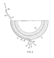
- FIG. 1 shows an orthopaedic prosthesis 10 which has a curved outer surface 12 having a channel 14 defined therein, an electrical conductor 16 positioned in the channel 14, and a switch 18 positioned at a location of the curved outer surface 12 and electrically coupled to the electrical conductor 16.
- the prosthesis 10 is an acetabular cup 20, the invention contemplates implementation of the invention in components of other orthopaedic joint prostheses.
- the orthopaedic prosthesis 10 may be embodied as any orthopaedic prosthesis having a curved outer surface, such as a component of a shoulder joint or a knee joint or a finger joint or an elbow joint or a hip joint or an ankle joint, especially when it can be difficult for a surgeon to determine whether the prosthesis component is properly seated into the patient's bone (e.g., when particular portions of the prosthesis 10 contact the patient's bone), for example due to visual limitations.
- the orthopaedic prosthesis 10 discussed in detail below is an acetabular cup 20, it should be appreciated that such features and description may be equally applicable to other orthopaedic prostheses including shoulder and ankle prostheses.
- the acetabular cup 20 includes the curved outer surface 12, a curved inner surface 22, and a rim surface 24 extending from the edge or rim 26 of the curved outer surface 12 to the edge or rim 28 of the curved inner surface 22.
- the acetabular cup 20 may be formed from any suitable material capable of being secured to the acetabulum of a patient and supporting a natural or artificial head portion of the patient's femur.
- the acetabular cup 20 may be formed from a ceramic material, a polymer material, a titanium alloy, or other implantable metal material.
- the cup 20 does not include mounting holes defined through the inner and outer surfaces 12, 22, respectively.
- the acetabular cup 20 may include any number of mounting holes, which are commonly used with bone screws to secure the cup 20 to the patient's bone.
- the acetabular cup 20 may be formed from a number of separate parts.
- the acetabular cup 20 may include a bearing 30 (see FIG. 2 ) configured to be received in a cavity 32 defined by the inner curved surface 22.
- the bearing provides an artificial surface on which the natural or artificial head portion of the femur of the patient may articulate.
- the bearing may be formed from any material suitable for such purpose.
- the bearing may be formed from a metallic material, a ceramic material, a polymeric material such as polyethylene or ultra-high molecular weight polypropylene (UHMWPE), and/or the like.
- the curved outer surface 12 of the cup 20 shown in FIG. 2 is electrically conductive.
- the curved outer surface 12 may have an electrical conductivity of at least about 5 S.m -1 .
- the acetabular cup 20 may include an electrically conductive coating or texture applied to the outer surface 12 so as to form the electrically conductive outer surface 12.
- the conductive coating may be configured to also enhance bone growth. Additionally, even in embodiments wherein the acetabular cup 20 is formed from an electrically conductive material, such as a metallic material, the electrically conductive coating may also be applied to the outer surface of the cup 20.
- the outer surface 12 of the acetabular cup 20 includes the channel 14 defined therein.
- the channel 14 extends from the rim 26 of the outer surface 12 to a predetermined location 13 of the outer surface 12.
- the location 13 to which the channel 14 extends may be any location of interest on the outer surface 12 that contacts the patient's bone when the acetabular cup 20 is properly seated therein.
- the channel 14 may extend from the rim 26 to a location of the outer surface 12 substantially corresponding to the apex of the dome-shaped outer surface 12.
- the electrical conductor 16 is positioned in the channel 14 and includes a first end 34 that extends out of the channel 14 at the rim 26 of the outer surface 12.
- the electrical conductor 16 extends out of the channel 14 a length sufficient enough such that the electrical conductor 16 may be grasped by an orthopaedic surgeon while the acetabular cup 20 is fully seated into the patient's bone.
- the electrical conductor 16 in the cup shown in the drawings is embodied as a wire, but may be embodied as other types of electrical conductors in other embodiments such as an electrical trace, rod, or other electrically conductive path.
- the electrical conductor 16 can include a non-electrically conductive cladding 36 and an electrically conductive inner core 38, which is surrounded by the cladding 36. It can be preferred for the cladding 36 to be formed from a non-electrically conductive polymer cladding and the electrically conductive inner core 38 to be formed from an electrically conductive polymer. However, the electrical conductor 16 may be formed from other bio-compatible materials in other embodiments.
- the cladding 36 provides an amount of electrical isolation to the inner core 38. To access the inner core 38, the cladding 36 may be stripped back or otherwise removed such that the inner core 38 extends from it as at the first end 34 of the electrical conductor 16 in FIG. 1 .
- the electrical conductor 16 may be held in place in the channel 14 by frictional forces or by use of an adhesive.
- the channel 14 may have a width slightly larger than the outer width of the cladding 36 such that the electrical conductor 16 may be pressed into the channel 14 and held in place by frictional forces.
- a bio-compatible adhesive may be used to secure the electrical conductor 16 in the channel 14.
- the adhesive may be semi-permanent such that the electrical conductor 16 may be removed from the channel 14 by application of an appropriate force as discussed below with reference to FIG. 8 .
- the switch 18 is positioned at the predetermined location 13 of the curved outer surface 12 (i.e., the location of interest that contacts the patient's bone when the cup 20 is properly seated).
- the switch 18 is positioned near the apex of the dome-shaped outer surface 12.
- the switch 18 may be a simple switch or a complex switch.
- the switch 18 can be embodied as a second end 40 of the electrical conductor 16.
- the switch 18 may be embodied as a more complex switch that is electrically coupled to electrical conductor 16.
- the switch 18 shown in FIGS. 1 to 4 is formed from the second end 40 of the electrical conductor 16 by removal of the non-conductive cladding 36, which exposes an end 42 of the inner core 38.
- the end 42 of the inner core 38 is positioned to extend out of the channel 14 and over a portion of the electrically conductive outer surface 12 without contacting the surface 12.
- the end 42 of the inner core 38 is pressed against the electrically conductive outer surface 12 by the patient's bone thereby establishing a connection between the electrical conductor 16 and the outer surface 12.
- the switch 18 includes two states, a non-conductive state and a conductive state.
- the first state the end 42 of the inner core 38 is spaced apart from the electrically conductive outer surface 12 and no electrical connection is established between the electrical conductor 16 and the outer surface 12.
- the switch 18 is positioned in the first state prior to implantation of the acetabular cup 20.
- the second state the end 42 of the inner core 38 is in contact with the electrically conductive outer surface 12 and an electrical connection is established between the electrical conductor 16 and the outer surface 12.
- an orthopaedic surgeon may determine whether the acetabular cup 20 is properly seated (i.e., whether the predetermined location 13 of the outer surface 12 is in contact with the patient's bone) by measuring the resistance between the outer surface 12 of the acetabular cup 20 and the first end 34 of the electrical conductor.
- a measured resistance value less than a predetermined threshold value is indicative of proper seating of the acetabular cup 20 because the outer surface 12 is in contact with the patient's bone causing the switch 18 to be positioned in the second, conductive state.
- the acetabular cup 20 may include a different number of switches. Each switch may be used to detect whether a corresponding location of the outer surface 12 is in contact with the patient's bone to thereby determine proper seating of the cup 20.
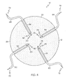
- the acetabular cup 20 includes four channels 50, 52, 54, 56, each similar to the channel 14, defined in the electrically conductive outer surface 12.
- An electrical conductor 60, 62, 64, 66, each similar to the electrical conductor 16, is positioned in each respective channel 50, 52, 54, 56.
- Each electrical conductor includes a first end 70, 72, 74, 76 extending from the respective channel 50, 52, 54, 56 at the rim 26 of the outer surface 12. Additionally, each electrical conductor 60, 62, 64, 66 includes a second end 80, 82, 84, 86, each of which forms a respective switch 90, 92, 94, 96 in the manner described above in regard to switch 18.
- the channels 50, 52, 54, 56 are defined in the outer surface 12 in a symmetrical pattern in the embodiment shown in FIG. 4 , it should be appreciated that the channels 50, 52, 54, 56 may be defined in any orientation relative to each other in other embodiments such that a corresponding switch 18, 90, 92, 94, 96 may be defined at any location of the outer surface 12.
- the switch 18 may be embodied as a complex switch.
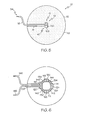
- the switch 18 may be embodied as a push-button switch 100.
- the push-button switch 100 may be embodied as any type of push-button switch.
- the push-button switch 100 may be a plunger-type switch having a plunger configured to be depressed when the switch contacts the patient's bone.
- the push-button switch 100 may be a dome-type switch having a dome or ceiling configured to be collapsed when the switch contacts the patient's bone.
- the push-button switch 100 is positioned in a recessed area 102 defined in the outer surface 12 of the acetabular cup 20 at the predetermined location 13.
- the push-button switch 100 may be secured in the recessed area 102 using any suitable adhesive or connector.
- the channel 14 extends from the rim 26 of the outer surface 12 to the recessed area 102.
- the push-button switch 100 is electrically coupled to the electrical conductor 16 and to the electrically conductive outer surface 12. As discussed above in regard to the switch 18, the push-button switch 100 includes two states, a non-conductive state and a conductive state. In the first state, no electrical connection is established between the electrical conductor 16 and the outer surface 12. In the second state, the switch 100 is activated (e.g., the switch 100 contacts a portion of the patient's bone) and an electrical connection is established between the electrical conductor 16 and the outer surface 12.
- the acetabular cup 20 may include any number of switches 18, 100 to detect whether corresponding locations of the outer surface are in contact with the patient's bone.
- the acetabular cup 20 may include four push-button switches 110, 112, 114, 116 positioned in respective recessed areas 120, 122, 124, 126.
- the outer surface 12 includes a number of channels 130, 132, 134, 136 connecting each of the recessed areas 120, 122, 124, 126.
- the channel 130 extends from the recessed area 120 to the recessed area 122.
- the channel 132 extends from the recessed area 122 to the recessed area 124.
- the channel 134 extends from the recessed area 124 to the recessed area 126.
- the channel 136 extends from the recessed area 126 to the recessed area 120.
- a channel 138 extends from the rim 26 of the electrically conductive outer surface 12 to the recessed area 120.
- An electrical conductor 140 is positioned in the channel 138 and is electrically coupled to the push-button switch 110.
- An electrical conductor 142 is positioned in the channel 130 and is electrically coupled to the switches 110, 112.
- An electrical conductor 144 is positioned in the channel 131 and is electrically coupled to the switches 112, 114.
- An electrical conductor 144 is positioned in the channel 134 and is electrically coupled to the switches 114, 116.
- An electrical conductor 146 is positioned in the channel 136 and is electrically coupled to the switch 116.
- the electrical conductor 146 extends from the channel 136, through the channel 138, and extends out of the channel 138 at the rim 26 of the electrically conductive outer surface 12.
- the embodiment of FIG. 6 includes two conductors 140, 146 extending out of the channel 138.
- the switches 110, 112, 114, 116 are not electrically coupled to the outer surface 12.
- the outer surface 12 may but need not be electrically conductive.
- the outer surface 12 is not electrically conductive.
- each of the switches 110, 112, 114, 116 either complete or break the electrical path defined by the electrical conductors 140, 142, 144, 146, 148.
- each switch 110, 112, 114, 116 has a first state in which the electrical path defined by the electrical conductors 140, 142, 144, 146, 148 is broken and a second state in which the electrical path is completed.
- an orthopaedic surgeon may determine whether the acetabular cup 20 is properly seated in such embodiments by measuring the continuity (or resistance) of the electrical path defined by the electrical conductors 140, 142, 144, 146, 148. Proper seating of the acetabular cup 20 is indicated when the electrical path is completed or broken depending on the type of switches 110, 112, 114, 116 used (i.e., the switches may be normally-open or normally-closed).
- the cup 20 shown in FIG. 6 includes four separate switches 110, 112, 114, 116, the cup 20 may include a greater or smaller number of switches in other embodiments.
- the acetabular cup 20 may include a single switch similar to the embodiment shown in FIG. 5 .
- the single switch is not coupled to the outer surface 12 in such embodiments, an additional electrical conductor is included and extends out of the channel 14.
- the outer surface 12 may not be electrically conductive in such embodiments.
- the outer surface 12 may be electrically conductive and each switch 110, 112, 114, 116 may be electrically coupled to the electrically conductive outer surface 12.
- the acetabular cup 20 includes a separate channel and electrical conductor for each switch similar to the embodiment described above with reference to FIG. 4 .
- an orthopaedic surgeon may determine whether the acetabular cup 12 is properly seated by measuring the resistance between the electrical conductor 16 (or conductors 70, 72, 74, 76 in the embodiment of FIG. 4 ) and the electrically conductive outer surface 12 of the cup (or between two conductors in the embodiment of FIG. 6 ).
- a measurement circuit 200 may be used.
- the measurement circuit 200 may be embodied as any type of circuit or device capable of measuring the resistance or impedance of a circuit.
- the measurement circuit 200 includes a first measurement probe 202, which is electrically coupled to the first end 34 of the electrical conductor 16.
- the measurement circuit 200 also includes a second measurement probe 204, which is electrically coupled to the electrically conductive outer surface 12 of the acetabular cup 20 (or the other electrical conductor in the embodiment of FIG. 6 ).
- the measurement circuit 200 measures the resistance between the these two points.
- a measured resistance below a predetermined threshold is indicative that the switch 18 has been positioned in the second state (i.e., the predetermined location 13 has contacted the patient's bone) and the acetabular cup 20 is properly positioned.
- the predetermined resistance threshold includes or otherwise accounts for the resistance of the electrical conductor 16, Rp, and the resistance of the outer surface 12, Rc.
- a method 300 for determining whether the orthopaedic prosthesis 10 is properly seated begins with step 302.
- the orthopaedic prosthesis 10 is positioned in the surgically-prepared bone of the patient.
- the prosthesis 10 is embodied as the acetabular cup 20
- the cup 20 is positioned in the patient's surgically-prepared acetabulum.
- the orthopaedic surgeon measures the resistance between the electrical conductor 16 and the electrically conductive outer surface 12 of the acetabular cup 20 (or between the two electrical conductors in embodiments similar to the embodiment of FIG. 6 ) in step 304.
- step 306 the measured resistance value is compared to the predetermined resistance threshold value. If the measured value is greater than the predetermined resistance threshold value, the position of the orthopaedic prosthesis 10 is adjusted in step 308. Additionally, in some embodiments, the bone of the patient may be re-shaped again in step 308. For example, in embodiments wherein the prosthesis 10 is embodied as an acetabular cup 20, the acetabulum of the patient may be re-reamed in step 308 to provide a better match to the acetabular cup 20. The resistance between the electrical conductor 16 and the outer surface 12 is again measured in step 306. If, however, the measured resistance is determined to be less than the predetermined resistance threshold in step 306, the orthopaedic prosthesis is considered to be properly seated.
- the orthopaedic surgeon may trim or remove the electrical conductor 16.
- the orthopaedic surgeon may remove the electrical conductor 16 from the channel 14 by pulling on the end 34 of the electrical conductor 16.
Landscapes
- Health & Medical Sciences (AREA)
- Orthopedic Medicine & Surgery (AREA)
- Heart & Thoracic Surgery (AREA)
- Vascular Medicine (AREA)
- Oral & Maxillofacial Surgery (AREA)
- Transplantation (AREA)
- Engineering & Computer Science (AREA)
- Biomedical Technology (AREA)
- Veterinary Medicine (AREA)
- Cardiology (AREA)
- Life Sciences & Earth Sciences (AREA)
- Animal Behavior & Ethology (AREA)
- General Health & Medical Sciences (AREA)
- Public Health (AREA)
- Physical Education & Sports Medicine (AREA)
- Prostheses (AREA)
Applications Claiming Priority (2)
| Application Number | Priority Date | Filing Date | Title |
|---|---|---|---|
| US12/338,510 US8075629B2 (en) | 2008-12-18 | 2008-12-18 | Orthopaedic prosthesis having a seating indicator |
| EP09178127A EP2198807B1 (fr) | 2008-12-18 | 2009-12-04 | Prothèse orthopédique dotée d'un indicateur d'assise |
Related Parent Applications (1)
| Application Number | Title | Priority Date | Filing Date |
|---|---|---|---|
| EP09178127.8 Division | 2009-12-04 |
Publications (2)
| Publication Number | Publication Date |
|---|---|
| EP2335652A1 true EP2335652A1 (fr) | 2011-06-22 |
| EP2335652B1 EP2335652B1 (fr) | 2012-07-25 |
Family
ID=41820422
Family Applications (2)
| Application Number | Title | Priority Date | Filing Date |
|---|---|---|---|
| EP09178127A Active EP2198807B1 (fr) | 2008-12-18 | 2009-12-04 | Prothèse orthopédique dotée d'un indicateur d'assise |
| EP10196769A Active EP2335652B1 (fr) | 2008-12-18 | 2009-12-04 | Prothèse orthopédique dotée d'un indicateur d'assise |
Family Applications Before (1)
| Application Number | Title | Priority Date | Filing Date |
|---|---|---|---|
| EP09178127A Active EP2198807B1 (fr) | 2008-12-18 | 2009-12-04 | Prothèse orthopédique dotée d'un indicateur d'assise |
Country Status (3)
| Country | Link |
|---|---|
| US (1) | US8075629B2 (fr) |
| EP (2) | EP2198807B1 (fr) |
| AT (1) | ATE542496T1 (fr) |
Families Citing this family (5)
| Publication number | Priority date | Publication date | Assignee | Title |
|---|---|---|---|---|
| US9539097B2 (en) * | 2007-11-08 | 2017-01-10 | Linares Medical Devices, Llc | Hip and knee joint assemblies incorporating debris collection architecture between the ball and seat interface |
| GB2529203B (en) * | 2014-08-13 | 2016-09-28 | James Wallace Mcminn Derek | Acetabular cup prosthesis |
| BR112017006012A2 (pt) | 2014-09-26 | 2017-12-19 | Renmatix Inc | mistura por adição, adesivos de madeira curados, madeiras compensadas, painéis de partículas orientadas, e composição |
| WO2019010336A1 (fr) | 2017-07-05 | 2019-01-10 | Renmatix, Inc. | Fabrication, isolation, purification et utilisations de compositions de particules de cellulose de petite taille particulaire |
| US20210147641A1 (en) | 2018-04-03 | 2021-05-20 | Renmatix, Inc. | Composites containing cellulose-based compositions |
Citations (4)
| Publication number | Priority date | Publication date | Assignee | Title |
|---|---|---|---|---|
| EP0353171A1 (fr) * | 1988-07-28 | 1990-01-31 | Jean-Philippe Fayard | Cupule de prothèse |
| FR2649005A1 (fr) * | 1989-07-03 | 1991-01-04 | Fischer Louis | Prothese cotyloidienne en matiere plastique |
| US20070179739A1 (en) * | 2006-02-01 | 2007-08-02 | Sdgi Holdings, Inc. | Implantable pedometer |
| WO2008089723A1 (fr) * | 2007-01-24 | 2008-07-31 | Kasimir Kisielinski | Dispositif et procédé permettant de mesurer la position d'une première partie par rapport à une autre et utilisation d'un dispositif de ce type |
Family Cites Families (19)
| Publication number | Priority date | Publication date | Assignee | Title |
|---|---|---|---|---|
| DE1918299B2 (de) * | 1969-04-10 | 1972-04-13 | Kraus, Werner, Dipl.-Ing., 8000 München | Schiene zur fuehrung und heilung frakturierter knochen |
| JPS63318939A (ja) | 1987-06-22 | 1988-12-27 | Kurashiki Chuo Biyouin | 寛骨臼角度計 |
| DE58900119D1 (de) | 1988-02-04 | 1991-06-27 | Protek Ag | Chirurgisches instrument zum einsetzen von hueftpfannen-prothesen. |
| IE880739A1 (en) | 1988-09-14 | 1990-03-14 | James Doyle | The alignment of hip joint sockets in hip joint replacement |
| US5141512A (en) * | 1989-08-28 | 1992-08-25 | Farmer Malcolm H | Alignment of hip joint sockets in hip joint replacement |
| US5318571A (en) * | 1992-05-14 | 1994-06-07 | Benson Gail M | Method and apparatus for simplifying total hip arthroplasty |
| EP0668063B1 (fr) | 1993-08-09 | 1999-07-14 | Tschirren, Ernst jun. | Coupe pour prothèse d'articulation, notamment prothèse de la hanche et insertion pour l'utilisation avec la coupe |
| EP0743049B1 (fr) * | 1995-05-18 | 2001-08-29 | Sulzer Orthopädie AG | Cupule acétabulaire artificielle |
| US5824078A (en) * | 1996-03-11 | 1998-10-20 | The Board Of Trustees Of The University Of Arkansas | Composite allograft, press, and methods |
| US5879401A (en) | 1996-05-17 | 1999-03-09 | Johnson & Johnson Professional, Inc. | Acetabular trial |
| US5904688A (en) | 1997-12-30 | 1999-05-18 | Bristol-Myers Squibb Co. | Orthopaedic assembly including an acetabular cup and cup inserter |
| JP3086805B1 (ja) | 1999-05-20 | 2000-09-11 | 悟 矢野 | 人工股関節置換術用装置 |
| US6623488B1 (en) * | 2000-03-16 | 2003-09-23 | Leone Innovations Corporation | Pelvic alignment assembly |
| US6302890B1 (en) * | 2000-03-16 | 2001-10-16 | Leone Innovations Corporation | Pelvic alignment assembly |
| CN100525721C (zh) | 2001-11-02 | 2009-08-12 | 国际专利所有者(开曼)有限公司 | 用于股骨上的外科手术夹具 |
| US7005573B2 (en) * | 2003-02-13 | 2006-02-28 | Parker-Hannifin Corporation | Composite EMI shield |
| CA2588739A1 (fr) * | 2004-12-02 | 2006-06-08 | Smith & Nephew, Inc. | Systemes permettant d'obtenir un plan de reference pour le montage d'un cotyle |
| KR100706030B1 (ko) | 2005-04-12 | 2007-04-11 | 한국과학기술원 | 참조기구를 이용한 비구컵 항행장치 및 이를 이용한 비구컵항행방법 |
| CN101370437A (zh) | 2005-11-18 | 2009-02-18 | 罗伯特·利耶 | 手术对准导向件 |
-
2008
- 2008-12-18 US US12/338,510 patent/US8075629B2/en active Active
-
2009
- 2009-12-04 AT AT09178127T patent/ATE542496T1/de active
- 2009-12-04 EP EP09178127A patent/EP2198807B1/fr active Active
- 2009-12-04 EP EP10196769A patent/EP2335652B1/fr active Active
Patent Citations (4)
| Publication number | Priority date | Publication date | Assignee | Title |
|---|---|---|---|---|
| EP0353171A1 (fr) * | 1988-07-28 | 1990-01-31 | Jean-Philippe Fayard | Cupule de prothèse |
| FR2649005A1 (fr) * | 1989-07-03 | 1991-01-04 | Fischer Louis | Prothese cotyloidienne en matiere plastique |
| US20070179739A1 (en) * | 2006-02-01 | 2007-08-02 | Sdgi Holdings, Inc. | Implantable pedometer |
| WO2008089723A1 (fr) * | 2007-01-24 | 2008-07-31 | Kasimir Kisielinski | Dispositif et procédé permettant de mesurer la position d'une première partie par rapport à une autre et utilisation d'un dispositif de ce type |
Also Published As
| Publication number | Publication date |
|---|---|
| US8075629B2 (en) | 2011-12-13 |
| EP2198807B1 (fr) | 2012-01-25 |
| US20100161070A1 (en) | 2010-06-24 |
| EP2335652B1 (fr) | 2012-07-25 |
| EP2198807A1 (fr) | 2010-06-23 |
| ATE542496T1 (de) | 2012-02-15 |
Similar Documents
| Publication | Publication Date | Title |
|---|---|---|
| US5326363A (en) | Provisional implant | |
| US9308102B2 (en) | Acetabular cup positioning device | |
| EP2198807B1 (fr) | Prothèse orthopédique dotée d'un indicateur d'assise | |
| US9943420B2 (en) | Liner having an integrated electrode | |
| US5989259A (en) | Femoral calcar stop for use with femoral stem inserter | |
| US5702477A (en) | Acetabular shell with supplemental support and method | |
| EP1154741B1 (fr) | Prothese orthopedique avec anneau de compression pour ciment | |
| US4827919A (en) | Femoral spacer | |
| US5814050A (en) | Hip offset-inset apparatus and method | |
| US8979940B2 (en) | Modular attachment mechanism in prosthetic implants | |
| EP0676932A1 (fr) | Procede et appareil pour simplifier l'arthroplastie totale de la hanche | |
| WO2018111429A1 (fr) | Ensemble d'essai d'arthroplastie de l'épaule comprenant des capteurs | |
| US8979939B2 (en) | Surgical prostheses | |
| WO2018200101A1 (fr) | Glénoïde augmenté avec rainure | |
| EP2399551B1 (fr) | Dispositif pour déterminer l'assise d'une prothèse orthopédique | |
| AU2020351036A1 (en) | Modular prosthesis for at least partial replacement of a tubular bone adjoining a joint | |
| US11273055B2 (en) | Tensor fascia latae (TFL) protector | |
| Hansen et al. | Primary cup fixation with different designs of trapeziometacarpal total joint trapezium components: a radiostereometric analysis in a pig bone model | |
| Guyen et al. | Tripolar versus conventional total hip implants range of motion to impingement test |
Legal Events
| Date | Code | Title | Description |
|---|---|---|---|
| PUAI | Public reference made under article 153(3) epc to a published international application that has entered the european phase |
Free format text: ORIGINAL CODE: 0009012 |
|
| AC | Divisional application: reference to earlier application |
Ref document number: 2198807 Country of ref document: EP Kind code of ref document: P |
|
| AK | Designated contracting states |
Kind code of ref document: A1 Designated state(s): AT BE BG CH CY CZ DE DK EE ES FI FR GB GR HR HU IE IS IT LI LT LU LV MC MK MT NL NO PL PT RO SE SI SK SM TR |
|
| AX | Request for extension of the european patent |
Extension state: AL BA RS |
|
| 17P | Request for examination filed |
Effective date: 20111219 |
|
| GRAP | Despatch of communication of intention to grant a patent |
Free format text: ORIGINAL CODE: EPIDOSNIGR1 |
|
| RIC1 | Information provided on ipc code assigned before grant |
Ipc: A61F 2/40 20060101ALI20120111BHEP Ipc: A61F 2/38 20060101ALI20120111BHEP Ipc: A61F 2/34 20060101ALI20120111BHEP Ipc: A61F 2/30 20060101AFI20120111BHEP |
|
| GRAS | Grant fee paid |
Free format text: ORIGINAL CODE: EPIDOSNIGR3 |
|
| GRAA | (expected) grant |
Free format text: ORIGINAL CODE: 0009210 |
|
| AC | Divisional application: reference to earlier application |
Ref document number: 2198807 Country of ref document: EP Kind code of ref document: P |
|
| AK | Designated contracting states |
Kind code of ref document: B1 Designated state(s): AT BE BG CH CY CZ DE DK EE ES FI FR GB GR HR HU IE IS IT LI LT LU LV MC MK MT NL NO PL PT RO SE SI SK SM TR |
|
| REG | Reference to a national code |
Ref country code: GB Ref legal event code: FG4D |
|
| REG | Reference to a national code |
Ref country code: CH Ref legal event code: EP Ref country code: CH Ref legal event code: NV Representative=s name: E. BLUM & CO. AG PATENT- UND MARKENANWAELTE VSP |
|
| REG | Reference to a national code |
Ref country code: AT Ref legal event code: REF Ref document number: 567396 Country of ref document: AT Kind code of ref document: T Effective date: 20120815 Ref country code: IE Ref legal event code: FG4D |
|
| REG | Reference to a national code |
Ref country code: DE Ref legal event code: R096 Ref document number: 602009008563 Country of ref document: DE Effective date: 20120913 |
|
| REG | Reference to a national code |
Ref country code: NL Ref legal event code: VDEP Effective date: 20120725 |
|
| REG | Reference to a national code |
Ref country code: AT Ref legal event code: MK05 Ref document number: 567396 Country of ref document: AT Kind code of ref document: T Effective date: 20120725 |
|
| REG | Reference to a national code |
Ref country code: LT Ref legal event code: MG4D Effective date: 20120725 |
|
| PG25 | Lapsed in a contracting state [announced via postgrant information from national office to epo] |
Ref country code: NO Free format text: LAPSE BECAUSE OF FAILURE TO SUBMIT A TRANSLATION OF THE DESCRIPTION OR TO PAY THE FEE WITHIN THE PRESCRIBED TIME-LIMIT Effective date: 20121025 Ref country code: AT Free format text: LAPSE BECAUSE OF FAILURE TO SUBMIT A TRANSLATION OF THE DESCRIPTION OR TO PAY THE FEE WITHIN THE PRESCRIBED TIME-LIMIT Effective date: 20120725 Ref country code: HR Free format text: LAPSE BECAUSE OF FAILURE TO SUBMIT A TRANSLATION OF THE DESCRIPTION OR TO PAY THE FEE WITHIN THE PRESCRIBED TIME-LIMIT Effective date: 20120725 Ref country code: CY Free format text: LAPSE BECAUSE OF FAILURE TO SUBMIT A TRANSLATION OF THE DESCRIPTION OR TO PAY THE FEE WITHIN THE PRESCRIBED TIME-LIMIT Effective date: 20120725 Ref country code: BE Free format text: LAPSE BECAUSE OF FAILURE TO SUBMIT A TRANSLATION OF THE DESCRIPTION OR TO PAY THE FEE WITHIN THE PRESCRIBED TIME-LIMIT Effective date: 20120725 Ref country code: IS Free format text: LAPSE BECAUSE OF FAILURE TO SUBMIT A TRANSLATION OF THE DESCRIPTION OR TO PAY THE FEE WITHIN THE PRESCRIBED TIME-LIMIT Effective date: 20121125 Ref country code: LT Free format text: LAPSE BECAUSE OF FAILURE TO SUBMIT A TRANSLATION OF THE DESCRIPTION OR TO PAY THE FEE WITHIN THE PRESCRIBED TIME-LIMIT Effective date: 20120725 Ref country code: FI Free format text: LAPSE BECAUSE OF FAILURE TO SUBMIT A TRANSLATION OF THE DESCRIPTION OR TO PAY THE FEE WITHIN THE PRESCRIBED TIME-LIMIT Effective date: 20120725 |
|
| PG25 | Lapsed in a contracting state [announced via postgrant information from national office to epo] |
Ref country code: GR Free format text: LAPSE BECAUSE OF FAILURE TO SUBMIT A TRANSLATION OF THE DESCRIPTION OR TO PAY THE FEE WITHIN THE PRESCRIBED TIME-LIMIT Effective date: 20121026 Ref country code: PL Free format text: LAPSE BECAUSE OF FAILURE TO SUBMIT A TRANSLATION OF THE DESCRIPTION OR TO PAY THE FEE WITHIN THE PRESCRIBED TIME-LIMIT Effective date: 20120725 Ref country code: SE Free format text: LAPSE BECAUSE OF FAILURE TO SUBMIT A TRANSLATION OF THE DESCRIPTION OR TO PAY THE FEE WITHIN THE PRESCRIBED TIME-LIMIT Effective date: 20120725 Ref country code: LV Free format text: LAPSE BECAUSE OF FAILURE TO SUBMIT A TRANSLATION OF THE DESCRIPTION OR TO PAY THE FEE WITHIN THE PRESCRIBED TIME-LIMIT Effective date: 20120725 Ref country code: SI Free format text: LAPSE BECAUSE OF FAILURE TO SUBMIT A TRANSLATION OF THE DESCRIPTION OR TO PAY THE FEE WITHIN THE PRESCRIBED TIME-LIMIT Effective date: 20120725 Ref country code: PT Free format text: LAPSE BECAUSE OF FAILURE TO SUBMIT A TRANSLATION OF THE DESCRIPTION OR TO PAY THE FEE WITHIN THE PRESCRIBED TIME-LIMIT Effective date: 20121126 |
|
| PG25 | Lapsed in a contracting state [announced via postgrant information from national office to epo] |
Ref country code: NL Free format text: LAPSE BECAUSE OF FAILURE TO SUBMIT A TRANSLATION OF THE DESCRIPTION OR TO PAY THE FEE WITHIN THE PRESCRIBED TIME-LIMIT Effective date: 20120725 |
|
| PG25 | Lapsed in a contracting state [announced via postgrant information from national office to epo] |
Ref country code: ES Free format text: LAPSE BECAUSE OF FAILURE TO SUBMIT A TRANSLATION OF THE DESCRIPTION OR TO PAY THE FEE WITHIN THE PRESCRIBED TIME-LIMIT Effective date: 20121105 Ref country code: CZ Free format text: LAPSE BECAUSE OF FAILURE TO SUBMIT A TRANSLATION OF THE DESCRIPTION OR TO PAY THE FEE WITHIN THE PRESCRIBED TIME-LIMIT Effective date: 20120725 Ref country code: EE Free format text: LAPSE BECAUSE OF FAILURE TO SUBMIT A TRANSLATION OF THE DESCRIPTION OR TO PAY THE FEE WITHIN THE PRESCRIBED TIME-LIMIT Effective date: 20120725 Ref country code: DK Free format text: LAPSE BECAUSE OF FAILURE TO SUBMIT A TRANSLATION OF THE DESCRIPTION OR TO PAY THE FEE WITHIN THE PRESCRIBED TIME-LIMIT Effective date: 20120725 Ref country code: RO Free format text: LAPSE BECAUSE OF FAILURE TO SUBMIT A TRANSLATION OF THE DESCRIPTION OR TO PAY THE FEE WITHIN THE PRESCRIBED TIME-LIMIT Effective date: 20120725 |
|
| PG25 | Lapsed in a contracting state [announced via postgrant information from national office to epo] |
Ref country code: SK Free format text: LAPSE BECAUSE OF FAILURE TO SUBMIT A TRANSLATION OF THE DESCRIPTION OR TO PAY THE FEE WITHIN THE PRESCRIBED TIME-LIMIT Effective date: 20120725 |
|
| PLBE | No opposition filed within time limit |
Free format text: ORIGINAL CODE: 0009261 |
|
| STAA | Information on the status of an ep patent application or granted ep patent |
Free format text: STATUS: NO OPPOSITION FILED WITHIN TIME LIMIT |
|
| 26N | No opposition filed |
Effective date: 20130426 |
|
| PG25 | Lapsed in a contracting state [announced via postgrant information from national office to epo] |
Ref country code: MC Free format text: LAPSE BECAUSE OF NON-PAYMENT OF DUE FEES Effective date: 20121231 Ref country code: BG Free format text: LAPSE BECAUSE OF FAILURE TO SUBMIT A TRANSLATION OF THE DESCRIPTION OR TO PAY THE FEE WITHIN THE PRESCRIBED TIME-LIMIT Effective date: 20121025 |
|
| REG | Reference to a national code |
Ref country code: DE Ref legal event code: R097 Ref document number: 602009008563 Country of ref document: DE Effective date: 20130426 |
|
| PG25 | Lapsed in a contracting state [announced via postgrant information from national office to epo] |
Ref country code: MT Free format text: LAPSE BECAUSE OF FAILURE TO SUBMIT A TRANSLATION OF THE DESCRIPTION OR TO PAY THE FEE WITHIN THE PRESCRIBED TIME-LIMIT Effective date: 20120725 |
|
| PG25 | Lapsed in a contracting state [announced via postgrant information from national office to epo] |
Ref country code: TR Free format text: LAPSE BECAUSE OF FAILURE TO SUBMIT A TRANSLATION OF THE DESCRIPTION OR TO PAY THE FEE WITHIN THE PRESCRIBED TIME-LIMIT Effective date: 20120725 |
|
| PG25 | Lapsed in a contracting state [announced via postgrant information from national office to epo] |
Ref country code: SM Free format text: LAPSE BECAUSE OF FAILURE TO SUBMIT A TRANSLATION OF THE DESCRIPTION OR TO PAY THE FEE WITHIN THE PRESCRIBED TIME-LIMIT Effective date: 20120725 Ref country code: LU Free format text: LAPSE BECAUSE OF NON-PAYMENT OF DUE FEES Effective date: 20121204 |
|
| PG25 | Lapsed in a contracting state [announced via postgrant information from national office to epo] |
Ref country code: HU Free format text: LAPSE BECAUSE OF FAILURE TO SUBMIT A TRANSLATION OF THE DESCRIPTION OR TO PAY THE FEE WITHIN THE PRESCRIBED TIME-LIMIT Effective date: 20091204 |
|
| PG25 | Lapsed in a contracting state [announced via postgrant information from national office to epo] |
Ref country code: MK Free format text: LAPSE BECAUSE OF FAILURE TO SUBMIT A TRANSLATION OF THE DESCRIPTION OR TO PAY THE FEE WITHIN THE PRESCRIBED TIME-LIMIT Effective date: 20120725 |
|
| REG | Reference to a national code |
Ref country code: FR Ref legal event code: PLFP Year of fee payment: 8 |
|
| REG | Reference to a national code |
Ref country code: FR Ref legal event code: PLFP Year of fee payment: 9 |
|
| PGFP | Annual fee paid to national office [announced via postgrant information from national office to epo] |
Ref country code: IT Payment date: 20221111 Year of fee payment: 14 |
|
| PG25 | Lapsed in a contracting state [announced via postgrant information from national office to epo] |
Ref country code: IT Free format text: LAPSE BECAUSE OF NON-PAYMENT OF DUE FEES Effective date: 20231204 |
|
| REG | Reference to a national code |
Ref country code: CH Ref legal event code: U11 Free format text: ST27 STATUS EVENT CODE: U-0-0-U10-U11 (AS PROVIDED BY THE NATIONAL OFFICE) Effective date: 20260101 |
|
| PGFP | Annual fee paid to national office [announced via postgrant information from national office to epo] |
Ref country code: DE Payment date: 20251028 Year of fee payment: 17 |
|
| PGFP | Annual fee paid to national office [announced via postgrant information from national office to epo] |
Ref country code: GB Payment date: 20251030 Year of fee payment: 17 |
|
| PGFP | Annual fee paid to national office [announced via postgrant information from national office to epo] |
Ref country code: FR Payment date: 20251110 Year of fee payment: 17 |
|
| PGFP | Annual fee paid to national office [announced via postgrant information from national office to epo] |
Ref country code: IE Payment date: 20251111 Year of fee payment: 17 |
|
| PGFP | Annual fee paid to national office [announced via postgrant information from national office to epo] |
Ref country code: CH Payment date: 20260101 Year of fee payment: 17 |