EP2335879A1 - Zange zum Abmontieren eines Scheibenwischerarms und damit verbundenes Verfahren - Google Patents
Zange zum Abmontieren eines Scheibenwischerarms und damit verbundenes Verfahren Download PDFInfo
- Publication number
- EP2335879A1 EP2335879A1 EP10193435A EP10193435A EP2335879A1 EP 2335879 A1 EP2335879 A1 EP 2335879A1 EP 10193435 A EP10193435 A EP 10193435A EP 10193435 A EP10193435 A EP 10193435A EP 2335879 A1 EP2335879 A1 EP 2335879A1
- Authority
- EP
- European Patent Office
- Prior art keywords
- nut
- jaws
- clamp
- head
- face
- Prior art date
- Legal status (The legal status is an assumption and is not a legal conclusion. Google has not performed a legal analysis and makes no representation as to the accuracy of the status listed.)
- Withdrawn
Links
Images

Classifications
-
- B—PERFORMING OPERATIONS; TRANSPORTING
- B25—HAND TOOLS; PORTABLE POWER-DRIVEN TOOLS; MANIPULATORS
- B25B—TOOLS OR BENCH DEVICES NOT OTHERWISE PROVIDED FOR, FOR FASTENING, CONNECTING, DISENGAGING, OR HOLDING
- B25B5/00—Clamps
- B25B5/06—Arrangements for positively actuating jaws
-
- B—PERFORMING OPERATIONS; TRANSPORTING
- B25—HAND TOOLS; PORTABLE POWER-DRIVEN TOOLS; MANIPULATORS
- B25B—TOOLS OR BENCH DEVICES NOT OTHERWISE PROVIDED FOR, FOR FASTENING, CONNECTING, DISENGAGING, OR HOLDING
- B25B27/00—Hand tools, specially adapted for fitting together or separating parts or objects whether or not involving some deformation, not otherwise provided for
- B25B27/0035—Hand tools, specially adapted for fitting together or separating parts or objects whether or not involving some deformation, not otherwise provided for for motor-vehicles
-
- B—PERFORMING OPERATIONS; TRANSPORTING
- B60—VEHICLES IN GENERAL
- B60S—SERVICING, CLEANING, REPAIRING, SUPPORTING, LIFTING, OR MANOEUVRING OF VEHICLES, NOT OTHERWISE PROVIDED FOR
- B60S1/00—Cleaning of vehicles
- B60S1/02—Cleaning windscreens, windows or optical devices
- B60S1/04—Wipers or the like, e.g. scrapers
- B60S1/32—Wipers or the like, e.g. scrapers characterised by constructional features of wiper blade arms or blades
- B60S1/34—Wiper arms; Mountings therefor
- B60S1/3425—Constructional aspects of the arm
- B60S1/3445—Joints between elements
- B60S1/3459—Joints between elements the element being a mounting head and a shaft
-
- B—PERFORMING OPERATIONS; TRANSPORTING
- B60—VEHICLES IN GENERAL
- B60S—SERVICING, CLEANING, REPAIRING, SUPPORTING, LIFTING, OR MANOEUVRING OF VEHICLES, NOT OTHERWISE PROVIDED FOR
- B60S1/00—Cleaning of vehicles
- B60S1/02—Cleaning windscreens, windows or optical devices
- B60S1/04—Wipers or the like, e.g. scrapers
- B60S1/0452—Position of the wipers relative to the vehicle
- B60S1/0469—Devices for assisting the wiper positioning on the vehicle
Definitions
- the present invention relates to a dismantling pliers for a windscreen wiper arm, and to a method of disassembling a windscreen wiper arm.
- This type of process has the disadvantage of requiring several operations, or even several tools, taking time for a single result, namely the disassembly of the wiper arm.
- the present invention is intended in particular to simplify and make quick disassembly of a wiper arm by proposing a simple and effective tool, and a disassembly method using such a tool.
- the upper jaws have a curved shape, in particular in a circular arc, to circumvent the nut head and not to impede the unscrewing of the nut during disassembly.
- the upper jaws only bear against the collar while skirting the nut head, for example a hexagonal nut head, intended to cooperate with a screwing / unscrewing tool.
- the lower jaws have a curved shape, particularly in a circular arc, to allow the circumvention of a coupling ring projecting from the underside of the drive head and provided internally. notches in relief so as to couple in rotation the drive shaft and the drive head. With this curved shape, the lower jaws only bear against the underside of the drive head while bypassing the coupling ring.
- the gripper encloses the collar of the nut and the drive head between its lower and upper jaws, and also between the lower and upper walls of the central part, thus optimizing the mechanical connection between nut and head. training.
- the lower wall is provided with a notch, in particular in a circular arc, to allow the bypassing of the coupling ring.
- the upper wall is provided with a notch, in particular in a circular arc, to circumvent the nut head and not to impede the unscrewing of the nut during disassembly.
- the clamp further comprises a hinge pin supported by the central piece, the jaws being rotatable about said hinge axis.
- the clamp further comprises elastic means for returning the jaws in the closed position, to allow automatic closure of the clamp.
- the clamp further comprises means for locking the jaws in the closed position, so as to prevent any opening of the clamp when unscrewing the nut.
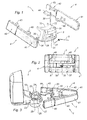
- the drive head 20 is provided with a coupling ring 26 projecting from the lower face 27 of the drive head 20, opposed to the upper face 23, and internally provided with notches 28 in relief so as to couple in rotation the drive shaft inside this coupling ring 26.
- the drive shaft is advantageously equipped notches raised on its free end threaded and intended to cooperate, in complementary form, with the notches 28 of the coupling ring 26.
- the notches of the drive shaft may for example be formed on a conical section and the coupling ring 26 may have a complementary internal surface of frustoconical shape.
- the orifice 31 for receiving the hinge pin 30 passes through the upper 32 and lower 34 walls from one side to the other.
- Each articulating arm 40 has an end secured to the jaw 4 and a free opposite end provided with an orifice in which is engaged the hinge pin 30.
- the hinge arms 40 extend partly in the window 37 formed in the central wall 36 of the central piece 3, between the upper 32 and lower 34 walls, to receive the hinge pin 30 taken in the orifice 31 formed in the upper walls 32 and lower 34 of the central piece 3.
- the elastic return means 5 are made in the form of a spring having a helical central portion wound around the hinge axis 30 and two opposite free ends and fixed on the respective jaws 4, so that this spring 5 exerts a thrust force on the jaws 4 tending to close these jaws 4, and thus to close the clamp 1.
- the clamp 1 further comprises locking means (not shown) of the jaws 4 in the closed position, so as to prevent any opening of the clamp 1 during the unscrewing of the nut 22.
- these locking means can be made in the form of a mechanical wedging device between the two jaws 4 or a rod which would jam on the rear portions 41 of the jaws 4 in adequate fingerprints.
- this method comprises an additional step of locking the jaws 4 in the closed position, between the step of closing the jaws 4 and the step unscrewing the nut 22.
Landscapes
- Engineering & Computer Science (AREA)
- Mechanical Engineering (AREA)
- Clamps And Clips (AREA)
Applications Claiming Priority (1)
| Application Number | Priority Date | Filing Date | Title |
|---|---|---|---|
| FR0959264A FR2954205B1 (fr) | 2009-12-21 | 2009-12-21 | Pince de demontage d'un bras d'essuie-vitre et procede de demontage associe. |
Publications (1)
| Publication Number | Publication Date |
|---|---|
| EP2335879A1 true EP2335879A1 (de) | 2011-06-22 |
Family
ID=42206792
Family Applications (1)
| Application Number | Title | Priority Date | Filing Date |
|---|---|---|---|
| EP10193435A Withdrawn EP2335879A1 (de) | 2009-12-21 | 2010-12-02 | Zange zum Abmontieren eines Scheibenwischerarms und damit verbundenes Verfahren |
Country Status (2)
| Country | Link |
|---|---|
| EP (1) | EP2335879A1 (de) |
| FR (1) | FR2954205B1 (de) |
Cited By (1)
| Publication number | Priority date | Publication date | Assignee | Title |
|---|---|---|---|---|
| CN106536291A (zh) * | 2014-07-24 | 2017-03-22 | 罗伯特·博世有限公司 | 用于鳍条刮水器的快速连接装置 |
Families Citing this family (1)
| Publication number | Priority date | Publication date | Assignee | Title |
|---|---|---|---|---|
| CN116061133B (zh) * | 2022-12-31 | 2025-07-29 | 中国航发沈阳发动机研究所 | 发动机压气机转子前轴颈轴承压紧螺母拧紧装置及方法 |
Citations (4)
| Publication number | Priority date | Publication date | Assignee | Title |
|---|---|---|---|---|
| GB2226522A (en) * | 1988-11-26 | 1990-07-04 | Calder Technical Services Ltd | Pipe welding clamp |
| DE4408732A1 (de) * | 1994-03-15 | 1995-09-21 | Teves Gmbh Alfred | Wischarm für eine Scheibenwischeranlage, insbesondere für Kraftfahrzeuge |
| EP0724991A1 (de) * | 1995-01-31 | 1996-08-07 | Valeo Systemes D'essuyage | Scheibenwischer mit verbesserten Mitteln zur Demontage seines Antriebskopfes |
| DE29904241U1 (de) * | 1999-03-09 | 1999-06-24 | Chen, Jenn-Hwang, He Mei, Changhua | Klemmhalter |
-
2009
- 2009-12-21 FR FR0959264A patent/FR2954205B1/fr not_active Expired - Fee Related
-
2010
- 2010-12-02 EP EP10193435A patent/EP2335879A1/de not_active Withdrawn
Patent Citations (4)
| Publication number | Priority date | Publication date | Assignee | Title |
|---|---|---|---|---|
| GB2226522A (en) * | 1988-11-26 | 1990-07-04 | Calder Technical Services Ltd | Pipe welding clamp |
| DE4408732A1 (de) * | 1994-03-15 | 1995-09-21 | Teves Gmbh Alfred | Wischarm für eine Scheibenwischeranlage, insbesondere für Kraftfahrzeuge |
| EP0724991A1 (de) * | 1995-01-31 | 1996-08-07 | Valeo Systemes D'essuyage | Scheibenwischer mit verbesserten Mitteln zur Demontage seines Antriebskopfes |
| DE29904241U1 (de) * | 1999-03-09 | 1999-06-24 | Chen, Jenn-Hwang, He Mei, Changhua | Klemmhalter |
Cited By (3)
| Publication number | Priority date | Publication date | Assignee | Title |
|---|---|---|---|---|
| CN106536291A (zh) * | 2014-07-24 | 2017-03-22 | 罗伯特·博世有限公司 | 用于鳍条刮水器的快速连接装置 |
| US10214185B2 (en) | 2014-07-24 | 2019-02-26 | Robert Bosch Gmbh | Quick connecting device for fin ray wiper |
| CN106536291B (zh) * | 2014-07-24 | 2019-11-26 | 罗伯特·博世有限公司 | 用于鳍条刮水器的快速连接装置 |
Also Published As
| Publication number | Publication date |
|---|---|
| FR2954205B1 (fr) | 2012-02-03 |
| FR2954205A1 (fr) | 2011-06-24 |
Similar Documents
| Publication | Publication Date | Title |
|---|---|---|
| EP1375073B1 (de) | Vorrichtung zum Spannen um einen Schaft unter Vorspannung zu bringen und hiermit verbundenes Verfahren | |
| EP2347471B1 (de) | Einrichtung zur erdung eines elektrischen leiters eines überlandkabels | |
| EP0469959B1 (de) | Klingenträger | |
| FR2658108A1 (fr) | Dispositif de serrage a action rapide. | |
| FR2643838A1 (fr) | Dispositif de fixation rigide pour des pieces suspendues telles que poincons de presse-plieuse | |
| EP1825944A1 (de) | Werkzeughalter-Dorn für die Ausstattung einer umlaufenden Maschine, die mit sequenzierten Mitteln zur radialen und axialen Verriegelung ausgestattet ist | |
| FR3025129A1 (fr) | Dispositif de prehension | |
| WO2016156695A1 (fr) | Dispositif de maintien d'une lame de coupe pivotante | |
| WO2018127663A1 (fr) | Poignee amovible munie d'un systeme d'ouverture avec un bouton pivotant | |
| EP2927491B1 (de) | Fluid-umwälzpumpe, die mit einem motor ausgestattet ist, der zwei sich frei drehende montierte teile umfasst | |
| EP0216717B1 (de) | Klemmzange mit selbsteinstellenden Backen | |
| FR2954205A1 (fr) | Pince de demontage d'un bras d'essuie-vitre et procede de demontage associe. | |
| CA1206064A (fr) | Obturateur destine a etre monte dans un corps | |
| WO2004095964A1 (fr) | Forme en plusieurs parties pour la fabricatiion de chaussures | |
| FR2920104A1 (fr) | Mandrin porte-outil pour l'equipement d'une machine tournante | |
| EP0314564A1 (de) | Greifwerkzeug, besonders zum Fernbedienen von Kabelverbindungsstiften | |
| EP3049346A1 (de) | Deckel mit einer dichtung zum verschliessen einer dose sowie anordnung aus einer dose und solch einem deckel | |
| EP0798186A1 (de) | Wischerarm für eine Scheibenwischeranlage,insbesondere für Kraftfahrzeuge | |
| EP1258389B1 (de) | Verschlussvorrichtung für eine Öffnung zum Befestigen eines Gegenstandes, wie z.B. einen Kraftfahrzeugsitz | |
| EP4056420B1 (de) | Einhängesystem für gliederketten und entsprechende verfahren | |
| FR2892752A1 (fr) | Dispositif de verrouillage securise d'un tampon ou couvercle a un cadre, notamment de regard de chaussee | |
| EP0207823A1 (de) | Zange zum Öffnen von unter Druck stehenden Behältern | |
| EP4436856B1 (de) | Bremsbelagträger, konfiguriert zum ausstatten einer schienenfahrzeugbremsanlage, die ein bremsgestänge umfasst, schienenfahrzeugbremssystem mit einem solchen bremsbelagträger und schienenfahrzeug | |
| EP3680531A1 (de) | Gelenkartige klemmhalterung für mindestens einen rohrförmigen gegenstand | |
| EP1722929B1 (de) | Greifklemmende für eine schraubvorrichtung |
Legal Events
| Date | Code | Title | Description |
|---|---|---|---|
| PUAI | Public reference made under article 153(3) epc to a published international application that has entered the european phase |
Free format text: ORIGINAL CODE: 0009012 |
|
| AK | Designated contracting states |
Kind code of ref document: A1 Designated state(s): AL AT BE BG CH CY CZ DE DK EE ES FI FR GB GR HR HU IE IS IT LI LT LU LV MC MK MT NL NO PL PT RO RS SE SI SK SM TR |
|
| AX | Request for extension of the european patent |
Extension state: BA ME |
|
| 17P | Request for examination filed |
Effective date: 20111221 |
|
| STAA | Information on the status of an ep patent application or granted ep patent |
Free format text: STATUS: THE APPLICATION HAS BEEN WITHDRAWN |
|
| 18W | Application withdrawn |
Effective date: 20120416 |