EP2335929A1 - Adapter für Tintenpatrone - Google Patents
Adapter für Tintenpatrone Download PDFInfo
- Publication number
- EP2335929A1 EP2335929A1 EP11160606A EP11160606A EP2335929A1 EP 2335929 A1 EP2335929 A1 EP 2335929A1 EP 11160606 A EP11160606 A EP 11160606A EP 11160606 A EP11160606 A EP 11160606A EP 2335929 A1 EP2335929 A1 EP 2335929A1
- Authority
- EP
- European Patent Office
- Prior art keywords
- adapter
- ink
- cartridge
- ink cartridge
- mounting portion
- Prior art date
- Legal status (The legal status is an assumption and is not a legal conclusion. Google has not performed a legal analysis and makes no representation as to the accuracy of the status listed.)
- Granted
Links
Images







Classifications
-
- B—PERFORMING OPERATIONS; TRANSPORTING
- B41—PRINTING; LINING MACHINES; TYPEWRITERS; STAMPS
- B41J—TYPEWRITERS; SELECTIVE PRINTING MECHANISMS, i.e. MECHANISMS PRINTING OTHERWISE THAN FROM A FORME; CORRECTION OF TYPOGRAPHICAL ERRORS
- B41J2/00—Typewriters or selective printing mechanisms characterised by the printing or marking process for which they are designed
- B41J2/005—Typewriters or selective printing mechanisms characterised by the printing or marking process for which they are designed characterised by bringing liquid or particles selectively into contact with a printing material
- B41J2/01—Ink jet
- B41J2/17—Ink jet characterised by ink handling
- B41J2/175—Ink supply systems ; Circuit parts therefor
- B41J2/17503—Ink cartridges
- B41J2/17513—Inner structure
-
- B—PERFORMING OPERATIONS; TRANSPORTING
- B41—PRINTING; LINING MACHINES; TYPEWRITERS; STAMPS
- B41J—TYPEWRITERS; SELECTIVE PRINTING MECHANISMS, i.e. MECHANISMS PRINTING OTHERWISE THAN FROM A FORME; CORRECTION OF TYPOGRAPHICAL ERRORS
- B41J2/00—Typewriters or selective printing mechanisms characterised by the printing or marking process for which they are designed
- B41J2/005—Typewriters or selective printing mechanisms characterised by the printing or marking process for which they are designed characterised by bringing liquid or particles selectively into contact with a printing material
- B41J2/01—Ink jet
- B41J2/17—Ink jet characterised by ink handling
- B41J2/175—Ink supply systems ; Circuit parts therefor
- B41J2/17503—Ink cartridges
- B41J2/1752—Mounting within the printer
-
- B—PERFORMING OPERATIONS; TRANSPORTING
- B41—PRINTING; LINING MACHINES; TYPEWRITERS; STAMPS
- B41J—TYPEWRITERS; SELECTIVE PRINTING MECHANISMS, i.e. MECHANISMS PRINTING OTHERWISE THAN FROM A FORME; CORRECTION OF TYPOGRAPHICAL ERRORS
- B41J2/00—Typewriters or selective printing mechanisms characterised by the printing or marking process for which they are designed
- B41J2/005—Typewriters or selective printing mechanisms characterised by the printing or marking process for which they are designed characterised by bringing liquid or particles selectively into contact with a printing material
- B41J2/01—Ink jet
- B41J2/17—Ink jet characterised by ink handling
- B41J2/175—Ink supply systems ; Circuit parts therefor
- B41J2/17503—Ink cartridges
- B41J2/17543—Cartridge presence detection or type identification
- B41J2/17546—Cartridge presence detection or type identification electronically
-
- B—PERFORMING OPERATIONS; TRANSPORTING
- B41—PRINTING; LINING MACHINES; TYPEWRITERS; STAMPS
- B41J—TYPEWRITERS; SELECTIVE PRINTING MECHANISMS, i.e. MECHANISMS PRINTING OTHERWISE THAN FROM A FORME; CORRECTION OF TYPOGRAPHICAL ERRORS
- B41J2/00—Typewriters or selective printing mechanisms characterised by the printing or marking process for which they are designed
- B41J2/005—Typewriters or selective printing mechanisms characterised by the printing or marking process for which they are designed characterised by bringing liquid or particles selectively into contact with a printing material
- B41J2/01—Ink jet
- B41J2/17—Ink jet characterised by ink handling
- B41J2/175—Ink supply systems ; Circuit parts therefor
- B41J2/17566—Ink level or ink residue control
Definitions
- an adapter for an ink cartridge which is configured to be removably mounted to a cartridge mounting portion of a recording apparatus, comprises a main body, and a particular portion positioned at the main body.
- the particular portion is configured to block light emitted from a particular optical sensor of the cartridge mounting portion when the adapter is inserted into the cartridge mounting portion.
- the adapter and the ink cartridge are separate members. In other words, the adapter is not coupled to the ink cartridge, and therefore the adapter and the ink cartridge can be handled separately and independently.
- the adapter further may comprise an operation portion extending from the main body in a particular direction. With this configuration, a user may readily remove the adapter from the cartridge mounting portion by grasping the operation portion.
- the adapter further may comprise a further portion positioned at the main body.
- the cartridge mounting portion further may comprise a further optical sensor.
- the further portion may be configured to block light emitted from the further optical sensor when the adapter is mounted to the cartridge mounting portion.
- the adapter may be configured to be inserted into the cartridge mounting portion in an insertion direction, and the particular portion may have a dimension in the insertion direction.
- the dimension of the particular portion may depend on a characteristic of the ink cartridge which is to be used with the adapter.
- Fig. 12 is a side, partially cross-sectional, view of the cartridge mounting portion of Fig. 5 , the adapter of Fig. 4 , and the ink cartridge of Figs. 2(A) and 2(B) , in which the adapter and the ink cartridge start to be removed.
- Fig. 13 is a side, partially cross-sectional, view of the cartridge mounting portion of Fig. 5 , the adapter of Fig. 4 , and the ink cartridge of Figs. 2(A) and 2(B) , in which the adapter and the ink cartridge are being removed.
- Fig. 17 is a side, partially cross-sectional, view of the cartridge mounting portion of Fig. 5 , the adapter of Fig. 14 , and the ink cartridge of Figs. 2(A) and 2(B) , in which the adapter and the ink cartridge are positioned in the cartridge mounting portion and the lock lever of the cartridge mounting portion contacts the ink cartridge.
- Fig. 18 is a side, partially cross-sectional, view of the cartridge mounting portion of Fig. 5 , the adapter of Fig. 14 , and the ink cartridge of Figs. 2(A) and 2(B) , in which the adapter and the ink cartridge are positioned in the cartridge mounting portion, the lock lever of the cartridge mounting portion contacts the ink cartridge, and the lock lever of the cartridge mounting portion is secured to the case of the cartridge mounting portion.
- Transferring device 253 comprises a first pair of transfer rollers 261 and a second pair of transfer rollers 262 positioned along transfer path 259.
- First pair of transfer rollers 261 is positioned on the upstream side of recording device 254 and second pair of transfer rollers 262 is positioned on the downstream side of recording device 254 along transfer path 259.
- Recording apparatus 250 also comprises a platen 264 positioned directly below recording device 254.
- the sheet of paper fed by feeding device 252 is transferred onto platen 264 by first pair of transfer rollers 261.
- Recording device 254 is configured to record an image on the sheet of paper being transferred over platen 264.
- the sheet of paper having passed over platen 264 is transferred by second pair of transfer rollers 262 to second tray 258, which is positioned at the downstream end of transfer path 259.
- Recording device 254 comprises a carriage 266, and a recording head 272 mounted in carriage 266.
- Carriage 266 is supported by rails (not shown) such that carriage 266 slides on rails in a direction perpendicular to the paper plane of Fig. 1 .
- Recoding head 272 is configured to eject ink onto the sheet of paper.
- Each of an area of left side outer face 45 and an area of right side outer face 46 is greater than each of an area of front outer face 41, an area of rear outer face 42, an area of top outer face 43, and an area of bottom outer face 44.
- Ink cartridge 25 is inserted into case 280 from front outer face 41-side.
- Pair of side walls 60 may be a pair of translucent flexible films, e.g. , transparent or semi-transparent flexible films.
- Ink cartridge 25 may comprise a pair of covers covering pair of side walls 60 from the exterior of pair of side walls 60 to reinforce the rigidity of ink cartridge 25.
- the specific gravity of float 73 is less than the specific gravity of ink in ink chamber 100.
- float 73 has a hollow space formed therein.
- Float 73 is configured to move up and down in accordance with increase and decrease of ink amount in ink chamber 100.
- pivotable member 70 pivots about shaft 66.
- indication portion 72 moves up and down in inner space 142.
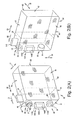
- Adapter 27 comprises a main body 36, a detection portion 186, and an operation portion 169.
- ink cartridge 25 comprises a front portion 28 positioned between front outer face 41 and a portion indicated by a alternate long and two short dashes line.
- Front portion 28 comprises air communication portion 80, detection portion 140, and ink supply portion 90.
- main body 36 has a container shape configured to accommodate front portion 28 of ink cartridge 25.
- main body 36 may accommodate substantially the entirety of ink cartridge 25.
- main body 36 may not accommodate any portions of ink cartridge 25.
- Main body 36 has a substantially rectangular parallelepiped shape corresponding to the shape of front portion 28 of ink cartridge 25.
- Main body 36 has a width in a width direction as indicated by an arrow 1031, a height in a height direction as indicated by an arrow 1032, and a depth in a depth direction as indicated by an arrow 1033.
- the height of main body 36 is greater than each of the width and the depth of main body 36.
- Main body 36 comprises a front wall 162, a top wall 163, a bottom wall 164 opposite top wall 163, a left side wall 165, and a right side wall 166 opposite left side wall 165.
- Each of top wall 163 and bottom wall 164 is connected to front wall 162, and each of left side wall 165 and right side wall 166 is connected to front wall 162, top wall 163, and bottom wall 164.
- Main body 36 has an opening 159 formed opposite front wall 162, and opening 159 is defined by ends of top wall 163, bottom wall 164, left side wall 165, and right side wall 166.
- Front wall 162, top wall 163, bottom wall 164, left side wall 165, and right side wall 166 define a space therein, and the space is opened to an exterior of main body 36 via opening 159.
- Adapter 27 is inserted into cartridge mounting portion 276 from front wall 162-side in insertion direction 30.
- width direction 1031, height direction 1032, and depth direction 1033 are parallel to width direction 31, height direction 32, and depth direction 33, respectively.
- Main body 36 has a cut-out 187 formed though front wall 162, left side wall 165, and right side wall 166.
- detection portion 140 is exposed to the exterior of main body 36 via cut-out 187. Therefore, cut-out 187 is formed at a position corresponding to front wall 140A and pair of side walls 140B, and has a shape and a size corresponding to front wall 140A and pair of side walls 140B.
- Adapter 27 is formed of an opaque material.
- Adapter 27 is manufactured by injection-molding a resin, e.g. ,nylon, polyethylene, polypropylene, polycarbonate, polyolefin, acrylonitrile butadiene styrene.'
- a coloring agent e.g. , carbon black, may be added in the resin.
- Main body 36 integrally comprises detection portion 186, and detection portion 186 comprises a pair of protrusions 192, 193. Pair of protrusions 192, 193 is positioned at top wall 163. Pair of protrusions 192, 193 extends from top wall 163 in a direction perpendicular to top wall 163.
- Each of pair of protrusions 192, 193 has a plate shape having a depth in depth direction 1033, a height in height direction 1032, and a width in width direction 1031, in which the height of each of pair of protrusions 192, 193 is greater than the width of each of pair of protrusions 192, 193, and the depth of each of pair of protrusions 192, 193 is greater than the height of each of pair of protrusions 192, 193.
- Optical path 236 is formed between a light emitting portion and a light receiving portion of optical sensor 235.
- the light emitting portion and the light receiving portion of optical sensor 235 faces each other.
- detection portion 186 blocks light, e.g. ,visible or infrared light, emitted from the light emitting portion.
- detection portion 186 prevents the light of optical sensor 235 from passing therethrough.
- adapter 27 may comprise a reflective member, e.g. , aluminum foil, positioned at detection portion 186, and when detection portion 186 receives light emitted from optical sensor 235, detection portion 186 reflects the light.
- Optical sensor 235 is electrically connected to a controller (not shown) of recording apparatus 250.
- the intensity of the light reaching the light receiving portion is greater than a threshold value.
- detection portion 186 blocks the light emitted from the light emitting portion, the intensity of the light reaching the light receiving portion is less than the threshold value.
- optical sensor 235 outputs a signal to the controller, and the controller determines that adapter 27 is mounted to cartridge mounting portion 276.
- Protrusion 192 and protrusion 193 are aligned in width direction 1031, and a gap 194 is formed therebetween.
- Top wall 163 has a slit 195 formed therethrough extending from opening 159 in depth direction 1033. Slit 195 is continuous with gap 194.
- Main body 36 comprises a bridge portion 189 positioned at front wall 162 and spanning cut-out 187 in height direction 1032.
- Bridge portion 189 has a plate shape having a depth in depth direction 1033, a height in height direction 1032, and a width in width direction 1031, in which the width of bridge portion 189 is greater than the depth of bridge portion 189, and the height of bridge portion 189 is greater than the width of bridge portion 189.
- Bridge portion 189 divides cut-out 187 into two openings 190, When bridge portion 189 is inserted into cartridge mounting portion 276, bridge portion 189 passes an optical path 231 of optical sensor 230, and blocks light emitted from optical sensor 230.
- Optical path 231 is formed between a light emitting portion and a light receiving portion of optical sensor 230.
- the light emitting portion and the light receiving portion of optical sensor 230 faces each other.
- adapter 27 is formed of opaque material, bridge portion 189 blocks light, e.g. , visible or infrared light, emitted from the light emitting portion.
- bridge portion 189 prevents the light of optical sensor 230 from passing therethrough.
- adapter 27 may comprise a reflective member, e.g. , aluminum foil, positioned at bridge portion 189, and when bridge portion 189 receives light emitted from optical sensor 230, bridge portion 189 reflects the light.
- optical sensor 230 When the insertion of adapter 27 into the cartridge mounting portion 276 is completed, the light emitting portion and the light receiving portion of optical sensor 230 faces openings 190, respectively, such that the light emitted from the light emitting portion may reach the light receiving portion though openings 190.
- Optical sensor 230 is electrically connected to a controller (not shown) of recording apparatus 230. When the light emitted from the light emitting portion is not blocked, the intensity of the light reaching the light receiving portion is greater than a threshold value. When bridge portion 189 blocks the light emitted from the light emitting portion, the intensity of the light reaching the light receiving portion is less than the threshold value. When the intensity of the light reaching the light receiving portion is less than the threshold value, optical sensor 230 outputs a signal to the controller.
- the depth of bridge portion 189 depends on the characteristic of ink cartridge 25 which is to be used with adapter 27, e.g. , the color of or the initial amount of ink stored in ink chamber 100 of ink cartridge 25 which is to be used with adapter 27.
- two types of ink cartridge 25 are used.
- One type of ink cartridge 25 stores a relatively small initial amount of ink in ink chamber 100
- another type of ink cartridge 25 stores a relatively large initial amount of ink ink chamber 100.
- the depth of bridge portion 189 of adapter 27 to be used with ink cartridge 25 storing the relatively large initial amount of ink is greater than the depth of bridge portion 189 of adapter 27 to be used with ink cartridge 25 storing the relatively small initial amount of ink.
- one type of ink cartridge 25 stores a black ink in ink chamber 100
- another type of ink cartridge 25 stores a color ink other than black in ink chamber 100.
- the depth of bridge portion 189 of adapter 27 to be used with ink cartridge 25 storing the black ink is greater than the depth of bridge portion 189 of adapter 27 to be used with ink cartridge 25 storing the color ink.
- Front wall 162 has a circular opening 177 formed therethrough in depth direction 1033. Opening 177 is positioned adjacent to top wall 163. The space defined by front wall 162, top wall 163, bottom wall 164, left side wall 165, and right side wall 166 is opened to the exterior of main body 36 via opening 177. Opening 177 is formed at a position corresponding to air communication portion 80.
- cartridge mounting portion 276 comprises a pushing portion 216, and the diameter of opening 177 is great enough to allow pushing portion 216 to be inserted through opening 177.
- adapter 27 is mounted to cartridge mounting portion 276, a portion of pushing portion 216 is positioned within opening 177. Then, when ink cartridge 25 is inserted into cartridge mounting portion 276, pushing portion 216 applies a force to rod 84, e.g. , pushes, rod 84 toward ink chamber 100 to cause the valve mechanism of air communication portion 80 to be opened.
- front wall 162 has a circular opening 178 formed therethrough in depth direction 1033. Opening 178 is positioned adjacent to bottom wall 164. The space defined by front wall 162, top wall 163, bottom wall 164, left side wall 165, and right side wall 166 is opened to the exterior of main body 36 via opening 178. Opening 178 is formed at a position corresponding to ink supply portion 90. The diameter of opening 178 is great enough to allow ink supply portion 90 to be inserted through opening 178.
- adapter 27 and ink cartridge 25 are mounted to cartridge mounting portion 276, a portion of ink supply portion 90 is positioned within opening 178, and a portion of ink pipe 285 is positioned within ink supply portion 90.
- Operation portion 169 has a substantially rectangular parallelepiped shape having a depth in depth direction 1033, a height in height direction 1032, and a width in width direction 1033, in which the depth of operation portion 169 is greater than each of the height and the width of operation portion 169.
- the width of operation portion 169 is less than the width of main body 36.
- Operation portion 169 extends from bottom wall 164 in a direction away from main body 36.
- Operation portion 169 comprises an extending portion 171 and a grasp portion 170.
- Extending portion 171 has a first end connected to main body 36 and a second end opposite the first end of extending portion 171.
- Grasp portion 170 is connected to the second end of extending portion 171.
- a user 170 may grasp grasp portion 170.
- Each of grasp portion 170 and extending portion 171 has a height in height direction 1032, and the height of grasp portion 170 is greater than the height of extending portion 171.
- Each of grasp portion 170 and extending portion 171 has a top surface and a bottom surface opposite bottom surface.
- the top surface of each of grasp portion 170 and extending portion 171 is positioned above the bottom surface of each of grasp portion 170 and extending portion 171.
- the top surface of grasp portion 170 is flush with the top surface of extending portion 171, and the bottom surface of grasp portion 170 is offset from the bottom surface of extending portion 171, such that the bottom surface of grasp portion 170 is connected to the bottom surface of extending portion via a connecting surface 173 extending in height direction 1032.
- operation portion 169 may not be connected to bottom wall 164, but may be connected to top wall 163, left side face 165, or right side wall 166.
- Cartridge mounting portion 276 comprises at least one case 280, e.g. , four cases 280 corresponding to four ink cartridges 25, respectively.
- Case 280 comprises a main body 281 and a lock lever 283.
- Main body 281 has an accommodating chamber 282 formed therein.
- Accommodating chamber 282 is configured to receive and accommodate ink cartridge 25 and adapter 27.
- Case 280 has an opening 284 formed therethrough and a end wall 286 positioned opposite opening 284.
- Adapter 27 is inserted into accommodating chamber 282 via opening 284 to be positioned to contact end wall 286 with front wall 162 facing end wall 286, and then ink cartridge 25 is inserted into accommodating chamber 282 via opening 284 such that front portion 28 of ink cartridge 25 is positioned in main body 36 of adapter 27.
- Case 280 comprises optical sensor 230 and optical sensor 235, e.g. , photo interrupters.
- Optical sensor 230 is positioned at end wall 286 of case 280.
- Case 280 comprises a top wall 287 and a bottom wall 288 opposite top wall 287, and optical sensor 235 is positioned at top wall 287 adjacent to end wall 286.
- Each of optical sensor 230 and optical sensor 235 comprises a light emitting portion and a light receiving portion.
- Each of optical sensor 230 and optical sensor 235 is connected to a controller (not shown) of recording apparatus 250, and is configured not to output an electric signal to the controller when the light receiving portion receives light having intensity of equal to or greater than a threshold value, but to output the electric signal to the controller when the light receiving portion receives light having intensity of less than the threshold value.
- Optical path 231 is formed between the light emitting portion and the light receiving portion of optical sensor 230. The light emitting portion and the light receiving portion of optical sensor 230 is aligned in a direction perpendicular to the paper plane of Fig. 5 , and the light emitting portion and the light receiving portion of optical sensor 230 face each other.
- optical path 236 is formed between the light emitting portion and the light receiving portion of optical sensor 235.
- the light emitting portion and the light receiving portion of optical sensor 235 is aligned in a direction perpendicular to the paper plane of Fig. 5 , and the light emitting portion and the light receiving portion of optical sensor 235 faces each other.
- bridge portion 189 or indication portion 72 When bridge portion 189 or indication portion 72 is positioned in optical path 231, the light emitted from the light emitting portion of optical sensor 230 is blocked, and the light receiving portion of optical sensor 230 receives light having intensity of less than the threshold value, e.g. , zero intensity.
- detection portion 186 when detection portion 186 is positioned in optical path 236, the light emitted from the light emitting portion of optical sensor 235 is blocked, and the light receiving portion of optical sensor 235 receives light having intensity of less than the threshold value, e.g. , zero intensity.
- Case 280 comprises ink pipe 285 extending from end wall 286 toward opening 284 in a direction opposite insertion direction 30.
- Ink pipe 285 penetrates through end wall 286, and an end of ink pipe 285 is exposed to the exterior of main body 281.
- Tube 278 is connected to the end of ink pipe 285.
- ink pipe 285 enters ink supply portion 90, such that the valve mechanism of ink supply portion 90 is opened by ink pipe 285.
- the valve mechanism of ink supply portion 90 is opened by ink pipe 285, ink chamber 100 is brought into fluid communication with ink pipe 285, and ink is allowed to be supplied from ink chamber 100 to recording head 272 via opening 91, ink pipe 285, and tube 278.
- Case 280 comprises a pushing portion 216 extending from end wall 286 toward opening 284 in a direction opposite insertion direction 30.
- pushing portion 216 is inserted through opening 177.
- pushing portion 216 applies a force to rod 84, e.g. , pushes rod 84 toward ink chamber 100 to cause the valve mechanism of air communication portion 80 to be opened.
- Lock lever 283 is configured to be selectively opened and closed to selectively cover and uncover opening 284.
- Case 280 comprises a shaft 290 positioned directly above opening 284, and a first end of lock lever 283 is coupled to shaft 290, such that lock lever 283 pivots about shaft 290.
- Lock lever 283 has an inner surface 296 and an outer surface 297 opposite inner surface 296. When lock lever 283 covers opening 284, inner surface 296 faces accommodating chamber 282.
- Lock lever 283 comprises an operation portion 293, and a claw 294.
- Claw 294 is positioned at inner surface 296 and at a second end of lock lever 283 opposite the first end of lock lever 283.
- Operation portion 293 is positioned at outer surface 297 adjacent to the second end of lock lever 283.
- Lock lever 290 has an opening 295 extending from inner surface 296 to outer surface 297 and positioned adjacent to the second end of lock lever 283.
- Case 280 has a groove 299 formed therein at a position below opening 284, and groove 299 is configured to engage claw 294.
- adapter 27 and ink cartridge 25 are inserted into accommodating chamber 282 and mounted to case 280 in the following manner.
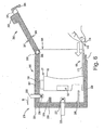
- adapter 27 When a user intends to insert adapter 27 into accommodating chamber 282, the user grasps grasp portion 170 as shown in Fig. 6 , and inserts adapter 27 into accommodating chamber 282 from front wall 162-side via opening 284 toward end wall 286.
- Bridge portion 189 first enters optical path 231 of optical sensor 230, and then when adapter 27 is further inserted, detection portion 186 enters optical path 236 of optical sensor 235. If adapter 27 is the one used with ink tank 25 storing the relatively large initial amount of ink or storing the black ink, the depth of bridge portion 189 is great enough such that bridge portion 189 is still positioned in optical path 231 of optical sensor 230 when detection portion 186 initially enters optical path 236 of optical sensor 235.
- adapter 27 is the one used with ink tank 25 storing the relatively small initial amount of ink or storing the color ink
- the depth of bridge portion 189 is short such that bridge portion 189 has passed optical path 231 of optical sensor 230 and is not positioned in optical path 231 of optical sensor 230 when detection portion 186 initially enters optical path 236 of optical sensor 235.
- the controller determines which type of ink tank 25 is to be mounted based on the output of optical sensor 230 when detection portion 186 initially enters optical path 236 of optical sensor 235.
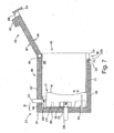
- adapter 27 contacts end wall 286 as shown in Fig. 7 , which completes the insertion of adapter 27.
- adapter 27 When adapter 27 contacts end wall 286, detection portion 186 is positioned in optical path 236 of optical sensor 235, optical path 231 of optical sensor 230 is positioned through openings 190, and a portion of pushing portion 216 is positioned within opening 177 as shown in Fig. 7 . Moreover, when adapter 27 contacts end wall 286, operation member 169 extends from bottom wall 164 of main body 36 to opening 284, such that grasp portion 170 is positioned outside accommodating chamber 282, and connecting surface 173 contacts an end surface 289 of bottom wall 288 positioned opposite end wall 286. The controller determines whether adapter 27 is mounted in case 280 based on the output of optical sensor 235.
- protrusion 145 is inserted into gap 194 and slit 195.
- Pushing portion 216 then applies a force to rod 84, e.g. , contacts and pushes rod 84 toward ink chamber 100 to cause the valve mechanism of air communication portion 80 to be opened.
- Ink chamber 100 is brought into fluid communication with the atmosphere via opening 81, and air is drawn into ink chamber 100 via air communication portion 80.
- Ink supply portion 90 then enters opening 178, and ink pipe 285 enters ink supply portion 90, such that the valve mechanism of ink supply portion 90 is opened by ink pipe 285.
- Ink chamber 100 is brought into fluid communication with ink pipe 285, and ink is allowed to be supplied from ink chamber 100 to recording head 272 via opening 91, ink pipe 285, and flexible tube 278.
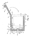
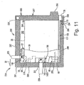
- detection portion 140 is exposed to the exterior of main body 36 of adapter 27 via openings 190, and detection portion 140 is positioned in optical path 231 of optical sensor 230 as shown in Fig. 10 .
- the controller of recording apparatus 250 determines that ink chamber 100 has a sufficient amount of ink therein, and when indication portion 72 is not positioned in optical path 231, the controller determines that ink chamber 100 does not have a sufficient amount of ink therein, based on the output from optical sensor 230.
- ink cartridge 25 When ink cartridge 25 is removed from case 280, a user disengages claw 294 from groove 299, and causes lock lever 283 to pivot upward. The user grasps grasp portion 170 as shown in Fig. 12 , and pulls adapter 27 in a direction opposite to insertion direction 30. Because front portion 28 of ink cartridge 25 is accommodated in the space of main body 36 of adapter 27, ink cartridge 25 moves toward opening 284 together with adapter 27 as shown in Fig. 13 . Therefore, the user can readily remove ink cartridge 25 from case 280.
- ink cartridge 25 Because the information about the characteristic of ink cartridge 25 is carried by adapter 27 as the depth of bridge portion 189, a common ink cartridge 25 can be used regardless of the characteristic of ink cartridge 25.
- ink cartridge 25 When ink cartridge 25 is used up, and if a user wishes to use a new ink cartridges 25 having the same characteristic as the used ink cartridge 25, the user does not have to purchase a new adapter 27. The user only has to purchase a new ink cartridge 25, and the user can use the new ink cartridge 25 with adapter 27 which the user has already had.
- ink cartridge 25 can be mounted to case 280 after adapter 27 is mounted to case 280. Moreover, ink cartridge 25 moves toward opening 284 together with adapter 27 when a user grasps grasp portion 170 and pulls adapter 27. Therefore, the user can readily remove ink cartridge 25 from case 280.
- adapter 107 according to another embodiment of the invention is depicted.
- adapter 107 comprises coil springs 109, 110.
- Coil springs 109, 110 are positioned at an outer surface of front wall 162 and extends from front wall 162 away from front wall 162 in depth direction 1033.
- Front wall 162 has a spring receiving chamber 112 formed therein at a position between top wall 163 and opening 177.
- Spring receiving chamber 112 is a cylindrical chamber extending from the outer surface of front wall 162 into front wall 162.
- front wall 162 has a spring receiving chamber 113 formed therein at a position between bottom wall 164 and opening 178.
- Spring receiving chamber 113 is a cylindrical chamber extending from the outer surface of front wall 162 into front wall 162. An end of coil spring 109 is supported at the bottom of spring receiving chamber 112, and an end of coil spring 110 is supported at the bottom of spring receiving chamber 113. Coil springs 105, 106 may be replaced with leaf springs or rubber springs.
- adapter 107 and ink cartridge 25 are inserted into accommodating chamber 282 and mounted to case 280 in the following manner.
- adapter 107 When adapter 107 is inserted into accommodating chamber 282 from front wall 162-side via opening 284 toward end wall 286, front wall 162 faces end wall 286, and coil springs 109, 110 are positioned between front wall 162 and end wall 286 with ends of coils springs 109, 110 contacting end wall 286.
- ink cartridge 25 is inserted into accommodating chamber 282 as shown in Fig. 16 .
- lock lever 283 pivots toward opening 284, and inner surface 296 of lock lever 283 contacts rear outer face 42 of ink cartridge 25 as shown in Fig. 17 .
- a user may push operation portion 293 to cause lock lever 283 to pivot.
- lock lever 283 pushes ink cartridge 25 against biasing forces of coil springs 109, 110, respectively, while coil springs 109, 110 contract, respectively.
- bridge portion 189 enters optical path 231 of optical sensor 230, and detection portion 186 enters optical path 236 of optical sensor 235.
- Pushing portion 216 applies a force to rod 84, e.g. , contacts and pushes rod 84 toward ink chamber 100 to cause the valve mechanism of air communication portion 80 to be opened.
- Ink chamber 100 is brought into fluid communication with the atmosphere via opening 81.
- Ink pipe 285 then enters ink supply portion 90, such that the valve mechanism of ink supply portion 90 is opened by ink pipe 285.
- Ink chamber 100 is brought into fluid communication with ink pipe 285, and ink is allowed to be supplied from ink chamber 100 to recording head 272 via opening 91, ink pipe 285, and tube 278.
- detection portion 140 is exposed to the exterior of adapter 27 via openings 190, and detection portion 140 is positioned in optical path 231 of optical sensor 230.
- lock lever 283 When the second end of lock lever 283 moves toward groove 299 and claw 294 engages groove 299, lock lever 283 is closed and secured to main body 281 as shown in Fig. 18 . After lock lever 283 is closed, ink cartridge 25 receives the biasing forces of coil springs 109, 110 toward opening 284 such that rear outer face 42 contact inner surface 296 of lock lever 283, and therefore ink cartridge 25 is securely retained in case 280.
- adapter 27 or 107 is first inserted into accommodating chamber 282, and then ink cartridge 25 is inserted into accommodating chamber 282. Nevertheless, adapter 27 or 107 and ink cartridge 25 may be inserted into accommodating chamber 282 at the same time.
- detection portion 186 of adapter 27 or 107 may have a plurality of slits formed therein, and the plurality of slits may extend in height direction 1032.
- the number of the plurality of slits may depend on the characteristic of ink cartridge 25.
- the plurality of slits may allow light to pass therethrough.
- the controller may determine what kind of ink cartridge 25 is to be mounted by counting the number of the plurality of slits of detection portion 186 of adapter 27 or 107.
- an adapter may not comprise an operation member.
- this adapter (27, 107), further comprising an operation portion (169) extending from the main body (36) in a particular direction.
- this adapter (107), wherein the main body (36) comprises a front wall (162), the adapter (107) further comprises a resilient member (109, 110) extending from the front wall (162), and the cartridge mounting portion (276) comprises an end wall (286), wherein when the adapter (107) is mounted to the cartridge mounting portion (276), the front wall (162) faces the end wall (286), and the resilient member (109, 110) is positioned between the front wall (162) and the end wall (286).
- this adapter (27, 107), wherein the front wall (162) further has a further opening (177) formed therethrough, the ink cartridge (25) further comprises an air communication portion (80) extending from the front outer face (41), and the cartridge mounting portion (276) comprise a pushing portion (216), wherein when the adapter (27, 107) and the ink chamber (25) are mounted to the cartridge mounting portion (276), a portion of the pushing portion (216) is positioned within the further opening (177) and the pushing portion (216) contacts the air communication portion (80), such that air is drawn into the ink chamber (100) via the air communication portion (80).
- the main body (36) further comprises a top wall (163), a bottom wall (164) opposite the top wall (163), a left side wall (165), and a right side wall (166) opposite the left side wall (165), each of the top wall (163) and the bottom wall (164) is connected to the front wall (162), and each of the left side wall (165) and the right side wall (166) is connected to the front wall (162), the top wall (163), and the bottom wall (164), the main body (36) has an opening (159) formed opposite the front wall (162), and the opening (159) is defined by ends of the top wall (163), the bottom wall (164), the left side wall (165), and the right side wall (166), the front wall (162), top wall (163), the bottom wall (164), the left side wall (165), and the right side wall (166) define a space therein, and the space is opened to an exterior of the main body (36) via the opening (159), wherein when the adapter (27, 107) and the ink cartridge
- this adapter (27, 107) further comprises a further portion (186) positioned at the main body (36), and the cartridge mounting portion (276) further comprise a further optical sensor (235), wherein the further portion (186) is configured to block light emitted from the further optical sensor (235) when the adapter (27, 107) is mounted to the cartridge mounting portion (276).
- the ink cartridge (25) further comprises a movable member (70) positioned within the ink chamber (100), and the movable member (70) is configured to move within the ink chamber (100) based on an amount of ink stored in the ink chamber (100), such that a portion (72) of the movable member (70) is positioned in a first position when the ink chamber (100) has a predetermined amount of ink therein, and the portion (72) of the movable member (70) is positioned in a second position which is different from the first position when the ink chamber (100) does not have the predetermined amount of ink therein, wherein the portion (72) of the movable member (70) is configured to block the light emitted from the particular optical sensor (230) when the ink cartridge (25) is mounted to the cartridge mounting portion (276) and when the portion (72) of the movable member (70) is positioned in the first position.
Landscapes
- Ink Jet (AREA)
Priority Applications (2)
| Application Number | Priority Date | Filing Date | Title |
|---|---|---|---|
| ES11160606T ES2563076T5 (es) | 2008-07-25 | 2008-07-25 | Sistema y uso de un adaptador para cartucho de tinta |
| EP11160606.7A EP2335929B2 (de) | 2008-07-25 | 2008-07-25 | System und Verwendung eines Adapters für Tintenpatronen |
Applications Claiming Priority (2)
| Application Number | Priority Date | Filing Date | Title |
|---|---|---|---|
| EP11160606.7A EP2335929B2 (de) | 2008-07-25 | 2008-07-25 | System und Verwendung eines Adapters für Tintenpatronen |
| EP08013451A EP2147793B1 (de) | 2008-07-25 | 2008-07-25 | Adapter für Tintenpatrone |
Related Parent Applications (3)
| Application Number | Title | Priority Date | Filing Date |
|---|---|---|---|
| EP08013451.3 Division | 2008-07-25 | ||
| EP08013451A Division EP2147793B1 (de) | 2008-07-25 | 2008-07-25 | Adapter für Tintenpatrone |
| EP08013451A Division-Into EP2147793B1 (de) | 2008-07-25 | 2008-07-25 | Adapter für Tintenpatrone |
Publications (3)
| Publication Number | Publication Date |
|---|---|
| EP2335929A1 true EP2335929A1 (de) | 2011-06-22 |
| EP2335929B1 EP2335929B1 (de) | 2016-01-13 |
| EP2335929B2 EP2335929B2 (de) | 2019-07-17 |
Family
ID=40039707
Family Applications (3)
| Application Number | Title | Priority Date | Filing Date |
|---|---|---|---|
| EP11160606.7A Active EP2335929B2 (de) | 2008-07-25 | 2008-07-25 | System und Verwendung eines Adapters für Tintenpatronen |
| EP11160584.6A Active EP2335928B1 (de) | 2008-07-25 | 2008-07-25 | Adapter für Tintenpatrone |
| EP08013451A Active EP2147793B1 (de) | 2008-07-25 | 2008-07-25 | Adapter für Tintenpatrone |
Family Applications After (2)
| Application Number | Title | Priority Date | Filing Date |
|---|---|---|---|
| EP11160584.6A Active EP2335928B1 (de) | 2008-07-25 | 2008-07-25 | Adapter für Tintenpatrone |
| EP08013451A Active EP2147793B1 (de) | 2008-07-25 | 2008-07-25 | Adapter für Tintenpatrone |
Country Status (3)
| Country | Link |
|---|---|
| EP (3) | EP2335929B2 (de) |
| DE (2) | DE202008018040U1 (de) |
| ES (3) | ES2431026T3 (de) |
Families Citing this family (3)
| Publication number | Priority date | Publication date | Assignee | Title |
|---|---|---|---|---|
| JP6019697B2 (ja) | 2012-04-19 | 2016-11-02 | ブラザー工業株式会社 | 印刷流体収容装置及び印刷流体供給装置 |
| CN203157373U (zh) * | 2012-12-27 | 2013-08-28 | 珠海纳思达企业管理有限公司 | 墨水罐用适配器及包含该适配器的墨盒 |
| CN107933121A (zh) * | 2017-12-29 | 2018-04-20 | 上海古鳌电子科技股份有限公司 | 一种金融票据打印装置及方法 |
Citations (13)
| Publication number | Priority date | Publication date | Assignee | Title |
|---|---|---|---|---|
| JPH03213349A (ja) | 1990-01-19 | 1991-09-18 | Canon Inc | インクジェット記録装置およびそのインクカートリッジ |
| US20040104984A1 (en) * | 1995-04-27 | 2004-06-03 | Hall Ronald W. | Method and apparatus for providing ink to an ink jet printing system |
| JP2005028614A (ja) | 2003-07-08 | 2005-02-03 | Brother Ind Ltd | インクカートリッジ |
| US20050168540A1 (en) * | 2004-01-29 | 2005-08-04 | Wilson John F. | Printing-fluid venting assembly |
| US20060023040A1 (en) * | 2004-07-29 | 2006-02-02 | Castle Steven T | Inkjet pen adapter |
| US20070070138A1 (en) | 2005-09-29 | 2007-03-29 | Brother Kogyo Kabushiki Kaisha | Ink cartridge |
| JP2007144811A (ja) | 2005-11-28 | 2007-06-14 | Brother Ind Ltd | インクカートリッジ |
| EP1826009A2 (de) | 2004-03-04 | 2007-08-29 | Brother Kogyo Kabushiki Kaisha | Tintenpatrone und Tintenstrahldrucker |
| EP1839871A1 (de) * | 2006-03-30 | 2007-10-03 | Brother Kogyo Kabushiki Kaisha | Tintenpatrone |
| EP1839873A1 (de) * | 2006-03-28 | 2007-10-03 | Brother Kogyo Kabushiki Kaisha | Tintenpatrone |
| US20070229615A1 (en) * | 2006-03-31 | 2007-10-04 | Brother Kogyo Kabushiki Kaisha | Ink Cartridges |
| EP1905594A1 (de) | 2006-09-27 | 2008-04-02 | Ninestar Image Co., Ltd. | Tintenkassettehalterung für Druckgeräthaltevorrichtung |
| EP2045079A1 (de) * | 2008-02-28 | 2009-04-08 | Brother Kogyo Kabushiki Kaisha | Tintenpatrone, Satz von Tintenpatronen und Tintenpatronenbestimmungssystem |
Family Cites Families (1)
| Publication number | Priority date | Publication date | Assignee | Title |
|---|---|---|---|---|
| DE69034212T2 (de) | 1989-08-05 | 2006-07-13 | Canon K.K. | Tintenstrahlaufzeichnungsgerät und Tintenkassette dafür |
-
2008
- 2008-07-25 DE DE202008018040U patent/DE202008018040U1/de not_active Expired - Lifetime
- 2008-07-25 ES ES11160584T patent/ES2431026T3/es active Active
- 2008-07-25 ES ES11160606T patent/ES2563076T5/es active Active
- 2008-07-25 DE DE202008018039U patent/DE202008018039U1/de not_active Expired - Lifetime
- 2008-07-25 EP EP11160606.7A patent/EP2335929B2/de active Active
- 2008-07-25 ES ES08013451T patent/ES2393011T3/es active Active
- 2008-07-25 EP EP11160584.6A patent/EP2335928B1/de active Active
- 2008-07-25 EP EP08013451A patent/EP2147793B1/de active Active
Patent Citations (13)
| Publication number | Priority date | Publication date | Assignee | Title |
|---|---|---|---|---|
| JPH03213349A (ja) | 1990-01-19 | 1991-09-18 | Canon Inc | インクジェット記録装置およびそのインクカートリッジ |
| US20040104984A1 (en) * | 1995-04-27 | 2004-06-03 | Hall Ronald W. | Method and apparatus for providing ink to an ink jet printing system |
| JP2005028614A (ja) | 2003-07-08 | 2005-02-03 | Brother Ind Ltd | インクカートリッジ |
| US20050168540A1 (en) * | 2004-01-29 | 2005-08-04 | Wilson John F. | Printing-fluid venting assembly |
| EP1826009A2 (de) | 2004-03-04 | 2007-08-29 | Brother Kogyo Kabushiki Kaisha | Tintenpatrone und Tintenstrahldrucker |
| US20060023040A1 (en) * | 2004-07-29 | 2006-02-02 | Castle Steven T | Inkjet pen adapter |
| US20070070138A1 (en) | 2005-09-29 | 2007-03-29 | Brother Kogyo Kabushiki Kaisha | Ink cartridge |
| JP2007144811A (ja) | 2005-11-28 | 2007-06-14 | Brother Ind Ltd | インクカートリッジ |
| EP1839873A1 (de) * | 2006-03-28 | 2007-10-03 | Brother Kogyo Kabushiki Kaisha | Tintenpatrone |
| EP1839871A1 (de) * | 2006-03-30 | 2007-10-03 | Brother Kogyo Kabushiki Kaisha | Tintenpatrone |
| US20070229615A1 (en) * | 2006-03-31 | 2007-10-04 | Brother Kogyo Kabushiki Kaisha | Ink Cartridges |
| EP1905594A1 (de) | 2006-09-27 | 2008-04-02 | Ninestar Image Co., Ltd. | Tintenkassettehalterung für Druckgeräthaltevorrichtung |
| EP2045079A1 (de) * | 2008-02-28 | 2009-04-08 | Brother Kogyo Kabushiki Kaisha | Tintenpatrone, Satz von Tintenpatronen und Tintenpatronenbestimmungssystem |
Also Published As
| Publication number | Publication date |
|---|---|
| DE202008018040U1 (de) | 2011-05-05 |
| ES2563076T3 (es) | 2016-03-10 |
| EP2335929B2 (de) | 2019-07-17 |
| EP2147793A1 (de) | 2010-01-27 |
| EP2335929B1 (de) | 2016-01-13 |
| EP2147793B1 (de) | 2012-10-24 |
| EP2335928B1 (de) | 2013-09-11 |
| DE202008018039U1 (de) | 2011-04-14 |
| ES2393011T3 (es) | 2012-12-17 |
| EP2335928A1 (de) | 2011-06-22 |
| ES2563076T5 (es) | 2020-02-14 |
| ES2431026T3 (es) | 2013-11-22 |
Similar Documents
| Publication | Publication Date | Title |
|---|---|---|
| US8172383B2 (en) | Ink cartridge assemblies having adapter for easily removing ink cartridge from mounting portion | |
| EP2279871B2 (de) | Tintenpatrone, Satz von Tintenpatronen und Tintenpatronenbestimmungssystem | |
| EP2433802B1 (de) | Tintenpatrone, Satz von Tintenpatronen und Tintenpatronenbestimmungssystem | |
| NZ578999A (en) | Ink cartridge, set of ink cartridges, and ink cartridge determination system | |
| EP2147792B1 (de) | Behälteranordnung | |
| CN101618635B (zh) | 用于墨盒的转接器 | |
| US7934821B2 (en) | Ink cartridges and ink supply systems | |
| AU2015401245A1 (en) | Liquid cartridge, liquid consuming apparatus, method of inserting liquid cartridge into cartridge mounting portion of liquid consuming apparatus, and use of liquid cartridge | |
| US8172382B2 (en) | Container arrangement including ink tank and adapter configured to be mounted to ink tank | |
| EP2335929B2 (de) | System und Verwendung eines Adapters für Tintenpatronen | |
| EP2147794B1 (de) | Adapter für Tintenpatrone | |
| HK1135356B (en) | Adapter for ink cartrdige | |
| HK1137702B (en) | Adapter for ink cartrdige | |
| HK1128660B (en) | Ink cartridge, set of ink cartridges, and ink cartridge determination system |
Legal Events
| Date | Code | Title | Description |
|---|---|---|---|
| PUAI | Public reference made under article 153(3) epc to a published international application that has entered the european phase |
Free format text: ORIGINAL CODE: 0009012 |
|
| AC | Divisional application: reference to earlier application |
Ref document number: 2147793 Country of ref document: EP Kind code of ref document: P |
|
| AK | Designated contracting states |
Kind code of ref document: A1 Designated state(s): AT BE BG CH CY CZ DE DK EE ES FI FR GB GR HR HU IE IS IT LI LT LU LV MC MT NL NO PL PT RO SE SI SK TR |
|
| 17P | Request for examination filed |
Effective date: 20111215 |
|
| GRAP | Despatch of communication of intention to grant a patent |
Free format text: ORIGINAL CODE: EPIDOSNIGR1 |
|
| RIN1 | Information on inventor provided before grant (corrected) |
Inventor name: YOSHINARI, AKIO Inventor name: NAKAMURA, HIROTAKE Inventor name: KANBE, TOMOHIRO Inventor name: HATTORI, SHINGO |
|
| GRAS | Grant fee paid |
Free format text: ORIGINAL CODE: EPIDOSNIGR3 |
|
| TPAC | Observations filed by third parties |
Free format text: ORIGINAL CODE: EPIDOSNTIPA |
|
| 17Q | First examination report despatched |
Effective date: 20131108 |
|
| GRAP | Despatch of communication of intention to grant a patent |
Free format text: ORIGINAL CODE: EPIDOSNIGR1 |
|
| INTG | Intention to grant announced |
Effective date: 20150702 |
|
| GRAS | Grant fee paid |
Free format text: ORIGINAL CODE: EPIDOSNIGR3 |
|
| GRAA | (expected) grant |
Free format text: ORIGINAL CODE: 0009210 |
|
| AC | Divisional application: reference to earlier application |
Ref document number: 2147793 Country of ref document: EP Kind code of ref document: P |
|
| AK | Designated contracting states |
Kind code of ref document: B1 Designated state(s): AT BE BG CH CY CZ DE DK EE ES FI FR GB GR HR HU IE IS IT LI LT LU LV MC MT NL NO PL PT RO SE SI SK TR |
|
| REG | Reference to a national code |
Ref country code: GB Ref legal event code: FG4D |
|
| REG | Reference to a national code |
Ref country code: CH Ref legal event code: EP |
|
| REG | Reference to a national code |
Ref country code: IE Ref legal event code: FG4D |
|
| REG | Reference to a national code |
Ref country code: AT Ref legal event code: REF Ref document number: 770234 Country of ref document: AT Kind code of ref document: T Effective date: 20160215 |
|
| REG | Reference to a national code |
Ref country code: DE Ref legal event code: R096 Ref document number: 602008042091 Country of ref document: DE |
|
| REG | Reference to a national code |
Ref country code: ES Ref legal event code: FG2A Ref document number: 2563076 Country of ref document: ES Kind code of ref document: T3 Effective date: 20160310 |
|
| REG | Reference to a national code |
Ref country code: NL Ref legal event code: FP |
|
| REG | Reference to a national code |
Ref country code: LT Ref legal event code: MG4D |
|
| REG | Reference to a national code |
Ref country code: AT Ref legal event code: MK05 Ref document number: 770234 Country of ref document: AT Kind code of ref document: T Effective date: 20160113 |
|
| REG | Reference to a national code |
Ref country code: FR Ref legal event code: PLFP Year of fee payment: 9 |
|
| PG25 | Lapsed in a contracting state [announced via postgrant information from national office to epo] |
Ref country code: NO Free format text: LAPSE BECAUSE OF FAILURE TO SUBMIT A TRANSLATION OF THE DESCRIPTION OR TO PAY THE FEE WITHIN THE PRESCRIBED TIME-LIMIT Effective date: 20160413 Ref country code: HR Free format text: LAPSE BECAUSE OF FAILURE TO SUBMIT A TRANSLATION OF THE DESCRIPTION OR TO PAY THE FEE WITHIN THE PRESCRIBED TIME-LIMIT Effective date: 20160113 Ref country code: GR Free format text: LAPSE BECAUSE OF FAILURE TO SUBMIT A TRANSLATION OF THE DESCRIPTION OR TO PAY THE FEE WITHIN THE PRESCRIBED TIME-LIMIT Effective date: 20160414 Ref country code: FI Free format text: LAPSE BECAUSE OF FAILURE TO SUBMIT A TRANSLATION OF THE DESCRIPTION OR TO PAY THE FEE WITHIN THE PRESCRIBED TIME-LIMIT Effective date: 20160113 |
|
| PG25 | Lapsed in a contracting state [announced via postgrant information from national office to epo] |
Ref country code: LT Free format text: LAPSE BECAUSE OF FAILURE TO SUBMIT A TRANSLATION OF THE DESCRIPTION OR TO PAY THE FEE WITHIN THE PRESCRIBED TIME-LIMIT Effective date: 20160113 Ref country code: PL Free format text: LAPSE BECAUSE OF FAILURE TO SUBMIT A TRANSLATION OF THE DESCRIPTION OR TO PAY THE FEE WITHIN THE PRESCRIBED TIME-LIMIT Effective date: 20160113 Ref country code: LV Free format text: LAPSE BECAUSE OF FAILURE TO SUBMIT A TRANSLATION OF THE DESCRIPTION OR TO PAY THE FEE WITHIN THE PRESCRIBED TIME-LIMIT Effective date: 20160113 Ref country code: IS Free format text: LAPSE BECAUSE OF FAILURE TO SUBMIT A TRANSLATION OF THE DESCRIPTION OR TO PAY THE FEE WITHIN THE PRESCRIBED TIME-LIMIT Effective date: 20160513 Ref country code: AT Free format text: LAPSE BECAUSE OF FAILURE TO SUBMIT A TRANSLATION OF THE DESCRIPTION OR TO PAY THE FEE WITHIN THE PRESCRIBED TIME-LIMIT Effective date: 20160113 Ref country code: SE Free format text: LAPSE BECAUSE OF FAILURE TO SUBMIT A TRANSLATION OF THE DESCRIPTION OR TO PAY THE FEE WITHIN THE PRESCRIBED TIME-LIMIT Effective date: 20160113 Ref country code: PT Free format text: LAPSE BECAUSE OF FAILURE TO SUBMIT A TRANSLATION OF THE DESCRIPTION OR TO PAY THE FEE WITHIN THE PRESCRIBED TIME-LIMIT Effective date: 20160513 |
|
| REG | Reference to a national code |
Ref country code: DE Ref legal event code: R026 Ref document number: 602008042091 Country of ref document: DE |
|
| PLBI | Opposition filed |
Free format text: ORIGINAL CODE: 0009260 |
|
| PG25 | Lapsed in a contracting state [announced via postgrant information from national office to epo] |
Ref country code: DK Free format text: LAPSE BECAUSE OF FAILURE TO SUBMIT A TRANSLATION OF THE DESCRIPTION OR TO PAY THE FEE WITHIN THE PRESCRIBED TIME-LIMIT Effective date: 20160113 Ref country code: EE Free format text: LAPSE BECAUSE OF FAILURE TO SUBMIT A TRANSLATION OF THE DESCRIPTION OR TO PAY THE FEE WITHIN THE PRESCRIBED TIME-LIMIT Effective date: 20160113 |
|
| PLAX | Notice of opposition and request to file observation + time limit sent |
Free format text: ORIGINAL CODE: EPIDOSNOBS2 |
|
| 26 | Opposition filed |
Opponent name: PEARL. GMBH Effective date: 20161012 |
|
| PG25 | Lapsed in a contracting state [announced via postgrant information from national office to epo] |
Ref country code: RO Free format text: LAPSE BECAUSE OF FAILURE TO SUBMIT A TRANSLATION OF THE DESCRIPTION OR TO PAY THE FEE WITHIN THE PRESCRIBED TIME-LIMIT Effective date: 20160113 Ref country code: SK Free format text: LAPSE BECAUSE OF FAILURE TO SUBMIT A TRANSLATION OF THE DESCRIPTION OR TO PAY THE FEE WITHIN THE PRESCRIBED TIME-LIMIT Effective date: 20160113 Ref country code: CZ Free format text: LAPSE BECAUSE OF FAILURE TO SUBMIT A TRANSLATION OF THE DESCRIPTION OR TO PAY THE FEE WITHIN THE PRESCRIBED TIME-LIMIT Effective date: 20160113 |
|
| PG25 | Lapsed in a contracting state [announced via postgrant information from national office to epo] |
Ref country code: BE Free format text: LAPSE BECAUSE OF FAILURE TO SUBMIT A TRANSLATION OF THE DESCRIPTION OR TO PAY THE FEE WITHIN THE PRESCRIBED TIME-LIMIT Effective date: 20160113 |
|
| PG25 | Lapsed in a contracting state [announced via postgrant information from national office to epo] |
Ref country code: SI Free format text: LAPSE BECAUSE OF FAILURE TO SUBMIT A TRANSLATION OF THE DESCRIPTION OR TO PAY THE FEE WITHIN THE PRESCRIBED TIME-LIMIT Effective date: 20160113 Ref country code: BG Free format text: LAPSE BECAUSE OF FAILURE TO SUBMIT A TRANSLATION OF THE DESCRIPTION OR TO PAY THE FEE WITHIN THE PRESCRIBED TIME-LIMIT Effective date: 20160413 |
|
| REG | Reference to a national code |
Ref country code: CH Ref legal event code: PL |
|
| PG25 | Lapsed in a contracting state [announced via postgrant information from national office to epo] |
Ref country code: MC Free format text: LAPSE BECAUSE OF FAILURE TO SUBMIT A TRANSLATION OF THE DESCRIPTION OR TO PAY THE FEE WITHIN THE PRESCRIBED TIME-LIMIT Effective date: 20160113 |
|
| PLBB | Reply of patent proprietor to notice(s) of opposition received |
Free format text: ORIGINAL CODE: EPIDOSNOBS3 |
|
| PG25 | Lapsed in a contracting state [announced via postgrant information from national office to epo] |
Ref country code: CH Free format text: LAPSE BECAUSE OF NON-PAYMENT OF DUE FEES Effective date: 20160731 Ref country code: LI Free format text: LAPSE BECAUSE OF NON-PAYMENT OF DUE FEES Effective date: 20160731 |
|
| REG | Reference to a national code |
Ref country code: IE Ref legal event code: MM4A |
|
| REG | Reference to a national code |
Ref country code: FR Ref legal event code: PLFP Year of fee payment: 10 |
|
| PG25 | Lapsed in a contracting state [announced via postgrant information from national office to epo] |
Ref country code: IE Free format text: LAPSE BECAUSE OF NON-PAYMENT OF DUE FEES Effective date: 20160725 |
|
| PG25 | Lapsed in a contracting state [announced via postgrant information from national office to epo] |
Ref country code: LU Free format text: LAPSE BECAUSE OF NON-PAYMENT OF DUE FEES Effective date: 20160725 |
|
| PG25 | Lapsed in a contracting state [announced via postgrant information from national office to epo] |
Ref country code: HU Free format text: LAPSE BECAUSE OF FAILURE TO SUBMIT A TRANSLATION OF THE DESCRIPTION OR TO PAY THE FEE WITHIN THE PRESCRIBED TIME-LIMIT; INVALID AB INITIO Effective date: 20080725 Ref country code: CY Free format text: LAPSE BECAUSE OF FAILURE TO SUBMIT A TRANSLATION OF THE DESCRIPTION OR TO PAY THE FEE WITHIN THE PRESCRIBED TIME-LIMIT Effective date: 20160113 |
|
| REG | Reference to a national code |
Ref country code: FR Ref legal event code: PLFP Year of fee payment: 11 |
|
| PG25 | Lapsed in a contracting state [announced via postgrant information from national office to epo] |
Ref country code: MT Free format text: LAPSE BECAUSE OF NON-PAYMENT OF DUE FEES Effective date: 20160731 Ref country code: TR Free format text: LAPSE BECAUSE OF FAILURE TO SUBMIT A TRANSLATION OF THE DESCRIPTION OR TO PAY THE FEE WITHIN THE PRESCRIBED TIME-LIMIT Effective date: 20160113 |
|
| PUAH | Patent maintained in amended form |
Free format text: ORIGINAL CODE: 0009272 |
|
| STAA | Information on the status of an ep patent application or granted ep patent |
Free format text: STATUS: PATENT MAINTAINED AS AMENDED |
|
| 27A | Patent maintained in amended form |
Effective date: 20190717 |
|
| AK | Designated contracting states |
Kind code of ref document: B2 Designated state(s): AT BE BG CH CY CZ DE DK EE ES FI FR GB GR HR HU IE IS IT LI LT LU LV MC MT NL NO PL PT RO SE SI SK TR |
|
| REG | Reference to a national code |
Ref country code: DE Ref legal event code: R102 Ref document number: 602008042091 Country of ref document: DE |
|
| REG | Reference to a national code |
Ref country code: NL Ref legal event code: FP |
|
| REG | Reference to a national code |
Ref country code: ES Ref legal event code: DC2A Ref document number: 2563076 Country of ref document: ES Kind code of ref document: T5 Effective date: 20200214 |
|
| P01 | Opt-out of the competence of the unified patent court (upc) registered |
Effective date: 20230529 |
|
| PGFP | Annual fee paid to national office [announced via postgrant information from national office to epo] |
Ref country code: GB Payment date: 20250612 Year of fee payment: 18 |
|
| PGFP | Annual fee paid to national office [announced via postgrant information from national office to epo] |
Ref country code: NL Payment date: 20250618 Year of fee payment: 18 |
|
| PGFP | Annual fee paid to national office [announced via postgrant information from national office to epo] |
Ref country code: FR Payment date: 20250612 Year of fee payment: 18 |
|
| PGFP | Annual fee paid to national office [announced via postgrant information from national office to epo] |
Ref country code: ES Payment date: 20250814 Year of fee payment: 18 |
|
| PGFP | Annual fee paid to national office [announced via postgrant information from national office to epo] |
Ref country code: DE Payment date: 20250616 Year of fee payment: 18 |
|
| PGFP | Annual fee paid to national office [announced via postgrant information from national office to epo] |
Ref country code: IT Payment date: 20250715 Year of fee payment: 18 |