EP2335954B9 - Agencement destiné à la fixation sur le plafond d'un véhicule de type monospace pour le transport de personnes - Google Patents
Agencement destiné à la fixation sur le plafond d'un véhicule de type monospace pour le transport de personnes Download PDFInfo
- Publication number
- EP2335954B9 EP2335954B9 EP10090013.3A EP10090013A EP2335954B9 EP 2335954 B9 EP2335954 B9 EP 2335954B9 EP 10090013 A EP10090013 A EP 10090013A EP 2335954 B9 EP2335954 B9 EP 2335954B9
- Authority
- EP
- European Patent Office
- Prior art keywords
- ceiling
- car body
- arrangement according
- duct
- vehicle
- Prior art date
- Legal status (The legal status is an assumption and is not a legal conclusion. Google has not performed a legal analysis and makes no representation as to the accuracy of the status listed.)
- Active
Links
Images




Classifications
-
- B—PERFORMING OPERATIONS; TRANSPORTING
- B61—RAILWAYS
- B61D—BODY DETAILS OR KINDS OF RAILWAY VEHICLES
- B61D27/00—Heating, cooling, ventilating, or air-conditioning
-
- B—PERFORMING OPERATIONS; TRANSPORTING
- B60—VEHICLES IN GENERAL
- B60H—ARRANGEMENTS OF HEATING, COOLING, VENTILATING OR OTHER AIR-TREATING DEVICES SPECIALLY ADAPTED FOR PASSENGER OR GOODS SPACES OF VEHICLES
- B60H1/00—Heating, cooling or ventilating devices
- B60H1/00357—Air-conditioning arrangements specially adapted for particular vehicles
- B60H1/00371—Air-conditioning arrangements specially adapted for particular vehicles for vehicles carrying large numbers of passengers, e.g. buses
-
- B—PERFORMING OPERATIONS; TRANSPORTING
- B60—VEHICLES IN GENERAL
- B60H—ARRANGEMENTS OF HEATING, COOLING, VENTILATING OR OTHER AIR-TREATING DEVICES SPECIALLY ADAPTED FOR PASSENGER OR GOODS SPACES OF VEHICLES
- B60H1/00—Heating, cooling or ventilating devices
- B60H1/00507—Details, e.g. mounting arrangements, desaeration devices
- B60H1/00557—Details of ducts or cables
- B60H1/00564—Details of ducts or cables of air ducts
-
- B—PERFORMING OPERATIONS; TRANSPORTING
- B60—VEHICLES IN GENERAL
- B60H—ARRANGEMENTS OF HEATING, COOLING, VENTILATING OR OTHER AIR-TREATING DEVICES SPECIALLY ADAPTED FOR PASSENGER OR GOODS SPACES OF VEHICLES
- B60H1/00—Heating, cooling or ventilating devices
- B60H1/24—Ventilating devices where the heating or cooling is irrelevant
- B60H1/241—Ventilating devices where the heating or cooling is irrelevant characterised by the location of ventilation devices in the vehicle
- B60H1/245—Ventilating devices where the heating or cooling is irrelevant characterised by the location of ventilation devices in the vehicle located in the roof
-
- B—PERFORMING OPERATIONS; TRANSPORTING
- B61—RAILWAYS
- B61D—BODY DETAILS OR KINDS OF RAILWAY VEHICLES
- B61D17/00—Construction details of vehicle bodies
- B61D17/04—Construction details of vehicle bodies with bodies of metal; with composite, e.g. metal and wood body structures
- B61D17/18—Internal lining, e.g. insulating
-
- B—PERFORMING OPERATIONS; TRANSPORTING
- B60—VEHICLES IN GENERAL
- B60R—VEHICLES, VEHICLE FITTINGS, OR VEHICLE PARTS, NOT OTHERWISE PROVIDED FOR
- B60R13/00—Elements for body-finishing, identifying, or decorating; Arrangements or adaptations for advertising purposes
- B60R13/02—Internal Trim mouldings ; Internal Ledges; Wall liners for passenger compartments; Roof liners
- B60R13/0212—Roof or head liners
Definitions
- the invention relates to an arrangement for attachment to a body ceiling of a large-capacity vehicle for passenger transport.
- the vehicle is in particular a rail vehicle, for example a tram, or a regional train.
- Passenger transport means, in particular, the transport of persons in so-called public passenger transport.
- the term "metropolitan area" refers in particular to passenger spaces for more than ten persons.
- large capacity rail vehicles have passenger compartments with seating for more than twenty people, for example, fifty people.
- this ceiling panel includes a supply air duct and consists of a few parts
- the ventilation of the passenger compartment is adjustable only on the distribution and size of the air outlet openings. In particular, high air speeds and turbulence at the air outlet openings to the passenger compartment can occur.
- connections of the air supply to a blower unit and adjacent vehicle parts must also be specially designed with a supply air duct. For example, transition pieces are needed that are individually adapted to the dimensions of the vehicle.
- US Pat. No. 6,416,116 B1 merely describes the connection of the supply air duct to a blower unit, but not to other vehicle parts, since it is an arrangement for a bus.
- DE 43 00 713 C1 which forms the preamble of claim 1, describes a fastening arrangement for a cover channel of a ventilation system of a vehicle, in particular a rail vehicle for passenger transport, which ceiling channel is composed of tunnel-shaped channel elements which are suspended above a vehicle interior ceiling with the edges of their legs on both sides of a vehicle roof, longitudinal profile members are placed, which in turn have at least one support element for lateral support of the individual elements.
- the support element of each profile carrier is located located on the inside of the ceiling channel and is located on the inside of the edge of the channel elements.
- the profile beams are attached at their longitudinal sides to outside the ceiling channel provided Hänbringeln, which in turn are applied to the outside of the edge of the channel elements.
- DE 196 41 642 A1 discloses an air conditioning unit mounted on a vehicle roof that has a unitary base made of a plastic material and a floor that can be mounted directly to the roof of the vehicle.
- the base and cover may be integrally molded from a synthetic resin, preferably a glass fiber reinforced thermoset.
- the distributor element may be made of plastic, preferably glass fiber reinforced plastic.
- the distributor element may be coated with a high pressure laminate.
- the arrangement should be composed of lightweight, yet dimensionally stable and inexpensive to produce parts that can be designed so that they have a low heat release rate in a fire.
- Another object of the invention is to provide a method of manufacturing such an arrangement.
- the invention relates to a large-capacity vehicle for passenger transport with such an arrangement.
- the ceiling panel for covering the car body ceiling of the vehicle is at least two-part standard construction, which can be used unchanged in the various types of vehicles. Therefore, the ceiling panel on a channel module, which forms a running in the longitudinal direction of the car body supply air duct for supplying air into the interior of the car body.
- a channel module which forms a running in the longitudinal direction of the car body supply air duct for supplying air into the interior of the car body.
- an additional module is provided which defines the supply air duct, in particular at least the side walls and preferably also has the upper boundary of the supply air duct to the vehicle ceiling.
- An advantage of an additional channel module is that the connections to a ventilation unit and optionally to further channel modules in adjacent vehicle parts or vehicles can be prefabricated.
- the duct module only needs to be attached to the carbody ceiling.
- the channel module is therefore particularly suitable for those vehicles which have a plurality of vehicle areas (eg vehicle areas separated by lathe positions and / or transition areas between the vehicle areas).
- the ceiling panel on a plate-shaped cover member which covers the supply air duct below and forms on its underside a visible from the passenger compartment surface of the ceiling panel, wherein the cover element is removable from the channel module. This allows cleaning and maintenance of the supply air duct.
- an additional duct module is that the materials can be specially adapted to the requirements of air ducts in passenger compartments.
- the materials may be selected to comply with fire safety regulations. This will be discussed in more detail.
- the walls of the supply air duct can be optimized for low resistance and easy cleaning.
- the surfaces of the channel walls can be designed so that they do not provide dirt particles with any attack surfaces or deposition surfaces to adhere to, HPL materials (see below) are well suited for this purpose.
- the cover element is preferably self-supporting, so that it can be fastened, for example, to opposite lateral end regions without changing its shape under its own weight.
- the ceiling panel is divided into the channel module, which (in the width direction of the vehicle) is mounted in the central area under the car body ceiling and in Voutenimplantation, the side, at the transition region between the car body top and the car body side wall laterally the channel module can be arranged.
- the Voutenimplantation also serve to cover or lining the inside of the car body. They can preferably be opened and / or are removable.
- the ceiling panel in the region of doors in the car body may have special elements which are adapted to the shape of the door devices, in particular to the so-called door protection boxes.
- the central part with the channel module and the cover element can be designed the same for the different vehicle types.
- the adaptation to the width which may vary with different types of vehicles, as well as optionally to the vehicle-type dependent devices such as door and the like, takes place in the lateral ceiling area with the cove elements and optionally other specially adapted elements.
- the assembly also includes a supporting structure that is part of the body panel or attached to the body panel. On the supporting structure, the ceiling panel, in particular the channel module, suspended. Preferably, at least part of the supporting structure extends laterally of the channel module, i. in the height range of the supply air duct at the side of the channel, and has fastening devices for securing other components of the vehicle. On such other components will be discussed in more detail. These include in particular handrails and handholds, on which passengers can hold in the passenger compartment, lights and / or consoles, luggage networks and the like facilities for the storage of luggage.
- the supporting structure comprises two fastening profiles running in the longitudinal direction of the vehicle, which are fastened laterally, on opposite sides of the channel module, to the vehicle body ceiling. Either directly or indirectly via other parts of the supporting structure, the channel module is connected in this case with the fastening profiles.
- An essential advantage of the invention is that on the one hand a few different components are used for the ceiling panel and on the other hand, the central part, namely the channel module with cover plate, even for the different types of vehicles in the same Way, in particular with the same width and preferably also with the same length in the longitudinal direction of the vehicle, can be used.
- the inlet side is connected to the supply air duct and outlet side via outlet openings to the passenger compartment, so that air from the supply air duct through the calming room and through the outlet openings in the Passenger compartment can flow.
- the air passes through a transition region having a reduced flow cross-section as it passes from the supply air channel into the settling chamber, the cross-sectional area of the transition region being smaller than the cross-sectional area in the settling chamber.
- the air velocities decrease after entering the calming space, it can take place a distribution of air and the air occurs evenly distributed over the various outlet openings at low air velocities in the passenger compartment.
- two calming chambers are located laterally of the supply air duct, on opposite sides of the supply air duct.
- a design with supply air duct and soothing space can be realized by a single, one-piece duct module. It must therefore not be attached to the ceiling different items within the car body.
- the duct module can be prefabricated and fixed with supply air duct and calming room on the car body cover.
- the cover element can cover both the draft channel and the calming room (s) below.
- One of the above-mentioned fasteners of the supporting structure is preferably used for attachment of handrails and / or handles, where passengers can hold within the passenger compartment.
- the support rods and / or handles can be attached to a supporting part of the fastening device, for example, be screwed.
- Such attachment can be made particularly stable and is preferably so stable that a support rod does not have to reach to the bottom of the car body to give a stable grip.
- the fastening device is covered at the bottom by a panel having a passage opening for the supporting part of the support rod and / or handle. In this way, the attachment area, where the transition between the carrying part and the fastening device, be covered so that it is not visible from the passenger compartment.
- the end of the supporting part of the support rod and / or the handle extends into the C-profile and can be positioned and fixed in a freely selectable position in the longitudinal direction of the vehicle.
- the ceiling panel on an elongated profile, which extends laterally of the channel module in the longitudinal direction of the vehicle.
- the outlet openings are formed through which the supply air flows out of the supply air duct into the passenger compartment.
- the cover element can be firmly connected to the elongated profile, for example glued. Further preferably, the cover element is releasably connected to the supporting structure via the elongate profile so that the cover element is detachable from the channel module together with the elongate profile.
- the elongated profiles may in particular be metal profiles, for example extruded aluminum sections, which preferably have guide surfaces for directing the outflowing air in desired directions.
- the duct module preferably has at least one exhaust air duct through which exhaust air can be discharged from the passenger compartment.
- the exhaust duct is, for example, if present, arranged above the calming room.
- the exhaust duct is in a special embodiment, unlike the supply air duct, not open by removing a channel wall, but the channel module preferably has a closed peripheral edge with channel walls, for example, on all four sides of the exhaust duct.
- the supply of the exhaust air from the passenger compartment in the exhaust duct can be realized for example by air inlet openings in the floor of the passenger compartment and by channels in the area of the sides of the car body, in particular along the door pillars, and / or in the region of the car body end.
- two exhaust ducts are formed on opposite sides of the supply air duct in the duct module, wherein the longitudinal axes of Exhaust ducts and the supply air duct parallel to each other. In the case of only a single exhaust duct, this also applies to the longitudinal axes of only one exhaust duct and the supply air duct.
- the channel module and / or the cover element is in each case made of at least one molded part with fiber-reinforced and foamed thermosets.
- This may in particular be glass-fiber-reinforced phenolic resin foam, which is used, for example, in the form of a plate with a wall thickness in the range of 6 to 10 mm.
- the cover element and optionally also other shaped parts of the channel module, have / have a top layer of high pressure laminated composite materials (HPL).
- HPL high pressure laminated composite materials
- the cover element is in particular the lower cover layer, which forms the viewing area for the passenger compartment. But it may also consist of the same upper material of the upper cover layer of the cover element.
- the high pressure laminated composite material may be paper webs impregnated with curable (thermosetting) synthetic resins.
- the outermost layer which may be referred to as a decorative layer, preferably consists of a colored in the desired color or printed and melaminharzgetränkten sheet paper.
- the core layers of the laminate consist e.g. from paper sheets soaked in phenolic resin.
- the thickness of the laminated cover layers may be in the range of 0.6 to 1.2 mm, for example.
- the mold parts of the channel module and / or the cover element may comprise plate-shaped sandwich material, wherein the opposite outer layers are formed by the described laminate, which is adhered to a core of the above-mentioned fiber-reinforced and foamed Duroplastmaterial.
- the fiber materials may in particular be fiber materials from the following group of materials: glass fibers, mesoscale carbon fibers, nanoscale cylindrical graphite fibers and any combinations thereof.
- the topcoat has a maximum average rate of heat emission (MAHRE) measured in the cone calorimeter of less than 90 kW / m 2 , preferably less than 65 kW / m 2 .
- MAHRE maximum average rate of heat emission
- the MAHRE value is obtained in a fire protection test in accordance with the international standard ISO 5660-1. In this case, the heat release rate of horizontally arranged samples in the ignition is determined by an external heat source.
- the above-mentioned material for the top layer already complies with the limit of 90 kW / m 2 for rail vehicles without further addition of fire-retardant materials that do not drive through tunnels.
- the material has a MAHRE of less than 15 kW / m 2 . This is the case, for example, with glass fiber reinforced phenolic foam when the wall thickness is between 6 and 10 mm.
- the channel module consists exclusively of the wall elements described above and optionally connecting parts for connecting the wall elements to the formation of the channels. Therefore, fire safety limits can be easily met.
- the invention relates to a method for producing an arrangement for attachment to a car body ceiling of a large-capacity vehicle for passenger transport, in particular a rail vehicle, according to claim 15.
- Embodiments of the method relate to the specific embodiments and variants of the arrangement which are described in this description.
- the removably mounted cover element also has the advantage that the downwardly facing surface, which can be seen from the passenger compartment, can be designed freely in terms of decor, structure and color. In particular, it is interchangeable with a different-looking, same-sized plate. All other parts, in particular the channel module, however, can always be designed in the same way regardless of the type of vehicle and regardless of the wishes of the vehicle operator.
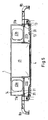
- Fig. 1 shows a perspective view of an arrangement with a channel module 1, which is covered by a cover element 4 below. Further illustrations of the arrangement are in the Fig. 2 and 11 to see, in particular the Fig. 5 to 11 merely show details of the arrangement and wherein in all figures parts of the arrangement are omitted to share the view of other parts. For example, the lateral cove elements 2 that are made of the Fig. 2 to 4 are recognizable, not in Fig. 1 shown. Furthermore, in Fig. 1 a portion of the components are not shown, which are attached to the supporting structure.
- the supporting structure is realized in the embodiment by two elongated profiles 3a, 3b extending in the longitudinal direction of the vehicle, which extend laterally, on both opposite sides of the channel module.
- the profiles 3 are preferably aluminum extruded profiles with several chambers for stabilizing the profiles.
- the chambers are from the sectional view of the Fig. 6 recognizable.
- the supporting parts 6 extend with their longitudinal direction from top to bottom and support the horizontally extending support rods 5a, 5b.
- the construction is due to the profiles 3a, 3b, which can be attached directly above the car body (not shown), so stable that the support rods do not need to be supported on the floor of the vehicle.
- Fig. 1 can also be seen that on the supporting profiles 3a, 3b fastening elements 8a, 8b are fastened laterally, which take a curved course down and terminate in a mounting plate.
- This mounting plate forms a flange for the attachment of in Fig. 1 not shown Voutenimplantation 2a, 2b and for the attachment of the longitudinally arranged between the Voutenimplantationn 2 connecting parts 9a, 9b for the connection of the assembly to door structures.
- This in Fig. 2 and Fig. 3 illustrated cove elements 2 and connecting elements 9 can be adapted individually to the conditions in a particular vehicle type. In particular, their width can be adjusted. In this way, the central part of the arrangement can always be carried out in the same way, regardless of the width of the vehicle.
- Fig. 4 Other parts that are attached to the supporting structure, namely on the profiles 3, are made Fig. 4 recognizable.
- lights 48a, 48b are visible laterally outside the areas in which the supporting parts 6 of the support rods 5 are attached to the profiles 3. It covers an aperture next to the light exit opening of the lamp 48 down from the area in which the respective supporting part 6 is connected to the holding profile 3.
- the supporting part 6, for example, an angled end piece 57, which extends through a slot in the aperture 49 or by a narrow distance between the aperture 49 and the air guide 11.
- the aperture of the lights is in Fig. 3 recognizable in the area left of the central center axis of the arrangement and denoted by the reference numeral 27a.
- it has three slot-like recesses 28a, 28b, 28c arranged in the longitudinal direction one behind the other for the luminaires 48.
- the aperture 49a or 49b is therefore, for example, an edge region of the aperture 27a next to recess 28.
- the attachment of the supporting part 6 (see Fig. 6 ) on the holding profile is realized by a screw, wherein a screw 44a projects through the end portion 43 of the supporting part 6b into a C-shaped part 41 of the supporting profile 3b.
- the C-profile 41 is open at the bottom and has at its opening opposite edges, which reduce the cross-section of the C-profile.
- a nut is used, which can be removed only at the longitudinally opposite ends of the C-profile 41 from this or can be inserted into this. In the middle region of the C-profile 41, the nut 42 can not fall out of the C-profile 41 or be removed.
- Fig. 1 . 5 and Figure 6 shows another variant of the supporting parts 6 of the support rod 5 as Fig. 3 and 4 ,
- the supporting parts are curved in their course from top to bottom slightly inwardly towards the central axis of the vehicle, whereas the supporting parts 6 in Fig. 1 . 5 and 6 straight down.
- the supporting parts 6 in Fig. 1 . 5 and 6 no angulation at its upper end, where they are connected to the supporting profile 3.
- Fig. 1 can be at the opposite longitudinal edges of the cover member 4 each an air guide 11a, 11b recognize.
- Gutleitprofil 11a is also a plurality of longitudinally extending slots 13 can be seen. Further slots may be due to the line of sight in Fig. 1 not be recognized.
- the central louver 31c is V-shaped with curved legs, wherein at some points the two lower free ends of the legs of the V are connected to each other by a stabilization 17 (eg Fig. 11 ).
- Fig. 6 shows a longitudinal section of the Lucasleitprofils 11, which has no such connection 17.
- the flow directions of the exiting through the slots 13 air are indicated by arrows.
- the channel module 1 has a central, in the longitudinal direction (perpendicular to the plane of the figure in Fig. 4 and 5 ) extending supply air duct 21 through which hot air and / or cold air can be performed as needed to ventilate the passenger compartment below the duct module 1.
- the hot air or cold air is provided for example by a known heating system and / or air conditioning.
- the air conditioning is for example over the front in Fig. 1 Port shown 12a connected to the supply air duct 21.
- the terminal 12a can also serve to connect the channel module with other channel modules in other parts of the vehicle.
- the terminals 7a, 7b, 7c, 7d in Fig. 1 . 2 and 3 serve the connection of the two laterally, on opposite sides of the supply air channel 21 in the channel module 1 formed exhaust air ducts 23a, 23b.
- the connection area in the back of the Fig. 1 is also from the Sectional view of Fig. 4 recognizable.
- the terminals 7 are connected (not shown) with further connecting lines, which preferably extend from bottom to top through the passenger compartment or at the edge of the passenger compartment and begin at air inlet openings in the region of the bottom of the passenger compartment.
- the exhaust air from the passenger compartment enters the lines and is introduced via the connecting pieces 7 in the exhaust air ducts 23a, 23b, through which the exhaust air is led to the heating and / or air conditioning and / or outdoors.
- To suck the exhaust air is preferably at a different location than in Fig. 1 to Fig. 11 shown arrangement, a corresponding fan or a plurality of fans arranged.
- the sectional view of the Fig. 4 . 5 and 6 shows, except the supply air duct 21 and the exhaust air ducts 23a, 23b, also laterally of the supply air duct 21 and below the exhaust ducts 23a, 23b formed calming chambers 22a, 22b, which also extend in the longitudinal direction of the vehicle or the arrangement.
- the calming rooms do not have to be in the longitudinal direction over the entire length of the Fig. 1 to 3 run arrangement shown.
- such calming chambers 22a, 22b are located wherever air outlet openings 13 are arranged in the air-conducting profiles 11.
- the calming chambers 22a, 22b are only partially formed by wall elements of the channel module 1. Only the in Fig. 7 shown lower wall elements 74, 75 and the lower ends of the U-shaped central portion 71 of the channel module 1 limit the calming chambers 22a, 22b. Down the calming rooms 22a, 22b (see Fig. 4 and 5 ) surrounded by the lateral edge regions of the cover member 4 and by the Dunleitprofile 11. Laterally outwardly limit the supporting profiles 3a, 3b (see, for example Fig. 6 Therefore, by removing the cover member 4 with the attached Heilleitprofilen 11a, 11b not only the central supply air duct 21 accessible, but also the two calming chambers 22a, 22b. For this reason, in particular the areas used for the supply air can be maintained and in particular cleaned.
- Fig. 7 shows the channel module 1 without cover element 4.
- the channel module 1 has a central, U-shaped central portion 71 which limits the central supply air duct 21 above and on the opposite sides.
- the two limbs of the U-shaped central part 71 also delimit the exhaust air ducts 23a, 23b arranged laterally of the supply air duct 21.
- the channel module 1 only has two other wall elements, namely the already mentioned lower wall elements 74, 75 for limiting the lateral exhaust ducts 23a, 23b.
- Wall elements extend over the entire longitudinal extent of the channel module 1 in the direction perpendicular to the plane of the figure Fig. 7 , These wall elements are preferably made of the material described above with reference to the figure description with HPL cover layers and a foamed, fiber-reinforced core.
- the connecting region between the wall element 74 and the leg of the U-shaped central part 71 is framed by a circle with the reference VIII. This framed area is enlarged in Fig. 8 shown.
- an angle section 76 is arranged on the inside in the exhaust air duct 23 a, wherein the angle section 76 preferably extends over the entire width of the wall member 74 and U-shaped, wherein the two short legs of the U are parallel to the leg of central part 71 or parallel to the lateral part of the element 72 extend.
- the angle piece 76 is fully adhered to the wall elements 71, 74, 72.
- a reinforcing element 77 preferably by an adhesive connection, be connected to the leg of the wall element 71 ( Fig. 8 ).
- Fig. 9 increases in the designated in IX circular area in Fig. 7 , There one recognizes for the angle profile 76 in the right exhaust air duct 23b that the short leg extends along the side part of the wall element 73, specifically on the inside of the exhaust air duct 23b.
- the angle pieces 76 in the two exhaust ducts 23a, 23b are designed in the same way and connected in the same way with the respective wall elements 70-75.
- a reinforcing region 77 may also be provided on the outside of the side part of the wall element 73.
- Fig. 10 shows the Deckelemerit 4 with the attached at its lateral edges
- Gutleitprofilen 11 a, 11 b For the left part of the Fig. 10 shows Fig. 11 increases the Lucasleitprofil 11a and the transition region at the side edge of the cover element 4.
- the air guide 11a has in the transition region to the element 4 a step-shaped profile in the direction of the center of the cover member 4 (right in Fig. 11 ) has a projecting portion 52. against the lower surface of this projecting portion 52, the end portion of the lid member 4 is brought into abutment and adhesively bonded thereto through an adhesive layer 51.
- the cover layer 73 which consists for example of HPL (high-pressure laminate), extends laterally beyond the core region of the cover element 4 to the left in Fig. 11 extended.
- the cover layer 73 lies there with its upper side on the air guide 11 and is there connected via an adhesive layer 51 with the air guide 11.
- the free end of the cover layer 73 engages in a U-shaped receptacle of the Lucasleitprofils 11 a. In this way, it is ensured that the individual layers of the cover layer 73 do not de-laminate.
Landscapes
- Engineering & Computer Science (AREA)
- Mechanical Engineering (AREA)
- Physics & Mathematics (AREA)
- Thermal Sciences (AREA)
- Life Sciences & Earth Sciences (AREA)
- Wood Science & Technology (AREA)
- Air-Conditioning For Vehicles (AREA)
- Vehicle Interior And Exterior Ornaments, Soundproofing, And Insulation (AREA)
- Fittings On The Vehicle Exterior For Carrying Loads, And Devices For Holding Or Mounting Articles (AREA)
Claims (15)
- Ensemble destiné à être fixé au niveau d'un plafond de caisse d'un véhicule de grand gabarit destiné au transport de personnes, en particulier d'un véhicule ferroviaire, sachant que l'ensemble présente :- un habillage de plafond,- une structure porteuse (3a, 3b), qui fait partie intégrante du plafond de caisse ou qui est fixée au niveau du plafond de caisse et au niveau de laquelle l'habillage de plafond est accroché,sachant que l'habillage de plafond présente :a) un module de conduit (1), qui forme un conduit d'air entrant (21) s'étendant dans le sens longitudinal de la caisse, destiné à une arrivée d'air dans l'intérieur de la caisse,b) un élément de recouvrement (4) en forme de panneau, qui recouvre le conduit d'air entrant (21) en bas et qui forme, sur son côté inférieur, une surface, visible depuis l'habitacle, de l'habillage de plafond, sachant que l'élément de recouvrement (4) peut être retiré du module de conduit (1),caractérisé en ce
que le module de conduit (1) et/ou l'élément de recouvrement (4) sont fabriqués à partir au moins d'une pièce moulée comprenant des matières thermodurcissables renforcées par des fibres et expansées, et en ce que l'élément de recouvrement (4) présente une couche de recouvrement constituée de matériaux composites laminés sous haute pression. - Ensemble selon la revendication 1, sachant que l'élément de recouvrement (4) est fabriqué à partir au moins d'une pièce moulée comprenant des matières thermodurcissables renforcées par des fibres et expansées et qu'il présente, au niveau de son côté inférieur qui forme la face visible pour l'habitacle, une couche de recouvrement constituée de matériaux composites laminés sous haute pression.
- Ensemble selon la revendication 1 ou 2, sachant qu'au moins un espace de stabilisation (22a, 22b) s'étendant dans le sens longitudinal de la caisse est configuré dans le module de conduit (1) sur le côté du conduit d'air entrant (21), lequel espace de stabilisation est relié, côté entrée, au conduit d'air entrant (21) et, côté sortie, par l'intermédiaire d'ouvertures de sortie (13), à l'habitacle de sorte que l'air peut circuler depuis le conduit d'air entrant (21), en passant par l'espace de stabilisation (22) et par les ouvertures de sortie (13), dans l'habitacle.
- Ensemble selon l'une quelconque des revendications 1 à 3, sachant qu'au moins une partie de la structure porteuse (3) s'étend sur le côté du module de conduit (1) et qu'elle présente à cet endroit des dispositifs de fixation (41) servant à fixer d'autres composants (6) du véhicule.
- Ensemble selon la revendication 4, sachant qu'un des dispositifs de fixation (41) est configuré afin de fixer des barres de maintien (5) et/ou des poignées de maintien, au niveau desquelles les passagers peuvent se tenir à l'intérieur de l'habitacle.
- Ensemble selon la revendication 5, sachant que le dispositif de fixation (41) servant à fixer des barres de maintien (5) et/ou des poignées de maintien est recouvert vers le bas par un cache (27a), qui présente une ouverture de passage destinée à une pièce de support (6) de la barre de maintien (5) et/ou de la poignée de maintien.
- Ensemble selon l'une quelconque des revendications précédentes, sachant que les ouvertures de sortie (13) servant à faire sortir l'air du conduit d'air entrant (21) dans l'habitacle sont formées dans au moins un profil (11a, 11b) s'étendant en longueur, lequel s'étend sur le côté du module de conduit (1) dans le sens longitudinal du véhicule.
- Ensemble selon la revendication 7, sachant que l'élément de recouvrement (4) est relié de manière solidaire au profil (11) s'étendant en longueur, lequel est relié de manière amovible à la structure de support (3) de sorte que l'élément de recouvrement (4) peut être retiré du module de conduit (1) conjointement avec le profil (11) s'étendant en longueur.
- Ensemble selon l'une quelconque des revendications précédentes, sachant que l'ensemble présente un élément voûté (2a, 2b) servant à habiller une zone de transition du plafond de caisse à une aile latérale de caisse, lequel élément voûté est disposé sur le côté du module de conduit (1).
- Ensemble selon la revendication 9, sachant que le module de conduit (1) peut être utilisé pour une largeur identique - vu dans un sens perpendiculaire au sens longitudinal du véhicule - pour une multitude de types de véhicule différents et que la largeur de l'élément voûté (2a, 2b) est choisie en fonction de la largeur du type de véhicule.
- Ensemble selon l'une quelconque des revendications précédentes, sachant qu'au moins un conduit d'air sortant (23) est formé dans le module de conduit (1), sur le côté du conduit d'air entrant (21) et de préférence au-dessus de l'espace de stabilisation (22), par lequel conduit d'air sortant l'air sortant peut être évacué de l'habitacle.
- Ensemble selon l'une quelconque des revendications précédentes, sachant que le module de conduit (1) et/ou l'élément de recouvrement (4) sont fabriqués respectivement à partir au moins d'une pièce moulée (71 - 75) comprenant des matières thermodurcissables renforcées par des fibres et expansées.
- Ensemble selon la revendication précédente, sachant que les matériaux à base de fibres sont choisis parmi le groupe de matériaux qui suit : les fibres de verre, les fibres de carbone de taille moyenne, des fibres de graphite cylindriques d'une taille à l'échelle du nanomètre et de combinaisons au choix de ces dernières.
- Ensemble selon l'une quelconque des revendications précédentes, sachant que l'élément de recouvrement (4) présente une couche de recouvrement (73) inférieure constituée de matériaux composites laminés sous haute pression.
- Procédé servant à fabriquer un ensemble destiné à être fixé au niveau d'un plafond de caisse d'un véhicule de grand gabarit servant au transport de personnes, en particulier d'un véhicule ferroviaire, en particulier servant à fabriquer l'ensemble selon l'une quelconque des revendications précédentes, sachant qu'est fourni ce qui suit :- un habillage de plafond ;- une structure de support (3a, 3b), qui fait partie intégrante du plafond de caisse ou qui est fixée au niveau du plafond de caisse, sachant que l'habillage de plafond est accroché au niveau de la structure de support (3),sachant que l'habillage de plafond est configuré de telle manièrea) qu'il présente un module de conduit (1), qui forme un conduit d'air entrant (21) s'étendant dans le sens longitudinal de la caisse, destiné à l'arrivée d'air dans l'intérieur de la caisse, etb) qu'il présente un élément de recouvrement (4) en forme de panneau, qui recouvre en bas le conduit d'air entrant (21) et qui forme, au niveau de son côté inférieur, une surface, visible depuis l'habitacle, de l'habillage de plafond, sachant que l'élément de recouvrement (4) peut être retiré du module de conduit (1),caractérisé en ce
qu'au moins une pièce moulée comprenant des matières thermodurcissables renforcées par des fibres et expansées est utilisée en tant que module de conduit (1) et/ou qu'élément de recouvrement (4), et en ce qu'un élément de recouvrement de ce type est utilisé en tant qu'élément de recouvrement (4), lequel présente une couche de recouvrement constituée de matériaux composites laminés sous haute pression.
Priority Applications (1)
| Application Number | Priority Date | Filing Date | Title |
|---|---|---|---|
| PL10090013T PL2335954T3 (pl) | 2009-12-18 | 2010-12-16 | Urządzenie do mocowania do sufitu nadwozia pojazdu w pojazdach wielkogabarytowych do przewozu pasażerów |
Applications Claiming Priority (1)
| Application Number | Priority Date | Filing Date | Title |
|---|---|---|---|
| DE102009059091A DE102009059091A1 (de) | 2009-12-18 | 2009-12-18 | Anordnung zur Befestigung an einer Wagenkasten-Decke eines Großraum-Fahrzeuges zur Personenbeförderung |
Publications (3)
| Publication Number | Publication Date |
|---|---|
| EP2335954A1 EP2335954A1 (fr) | 2011-06-22 |
| EP2335954B1 EP2335954B1 (fr) | 2015-05-20 |
| EP2335954B9 true EP2335954B9 (fr) | 2015-08-19 |
Family
ID=43802886
Family Applications (1)
| Application Number | Title | Priority Date | Filing Date |
|---|---|---|---|
| EP10090013.3A Active EP2335954B9 (fr) | 2009-12-18 | 2010-12-16 | Agencement destiné à la fixation sur le plafond d'un véhicule de type monospace pour le transport de personnes |
Country Status (4)
| Country | Link |
|---|---|
| EP (1) | EP2335954B9 (fr) |
| DE (1) | DE102009059091A1 (fr) |
| ES (1) | ES2539954T3 (fr) |
| PL (1) | PL2335954T3 (fr) |
Families Citing this family (19)
| Publication number | Priority date | Publication date | Assignee | Title |
|---|---|---|---|---|
| JP5787610B2 (ja) * | 2011-05-11 | 2015-09-30 | 日本車輌製造株式会社 | 鉄道車両の天井構造 |
| DE102012204687A1 (de) * | 2012-03-23 | 2013-09-26 | Siemens Aktiengesellschaft | Schienenfahrzeug mit Klimakanal im Dachbereich und Verfahren zum Aufbau eines Dachbereichs eines Schienenfahrzeugs |
| DE102013206535A1 (de) * | 2013-04-12 | 2014-10-16 | Siemens Aktiengesellschaft | Schienenfahrzeugwagenkasten |
| DE102013214310A1 (de) * | 2013-07-22 | 2015-01-22 | Siemens Aktiengesellschaft | Schienenfahrzeugwagen |
| ES2540924B1 (es) * | 2015-03-04 | 2016-02-12 | Rolen Technologies & Products, S.L. | Bloque de techo para trenes, con instalaciones de aire integradas |
| CN104875763A (zh) * | 2015-05-20 | 2015-09-02 | 常州大学 | 一种轨道客车新风混合装置 |
| EP3127774B1 (fr) | 2015-08-06 | 2020-11-25 | Bombardier Transportation GmbH | Système de conduit d'air intégré dans les profils de toit de carrosserie |
| EP3168104B1 (fr) * | 2015-11-16 | 2020-05-06 | Bombardier Transportation GmbH | Module de diffuseur d'air linéaire comprenant un élément de support multifonctionnel pour une carrosserie d'un véhicule de transport public |
| CN106428060A (zh) * | 2016-09-29 | 2017-02-22 | 中车长春轨道客车股份有限公司 | 单轨车辆整体式顶板结构 |
| DE102017207209A1 (de) * | 2017-04-28 | 2018-10-31 | Siemens Aktiengesellschaft | Befestigungsvorrichtung für ein Schienenfahrzeug |
| FR3066986B1 (fr) * | 2017-06-02 | 2020-08-28 | Alstom Transp Tech | Gaine de diffusion d'air pour systeme d'aeration, notamment de vehicule ferroviaire |
| CN111284513A (zh) * | 2018-12-07 | 2020-06-16 | 中车唐山机车车辆有限公司 | 风道及轨道车辆及其清理方法 |
| CN111806482B (zh) * | 2019-04-10 | 2021-09-10 | 中车唐山机车车辆有限公司 | 轨道列车 |
| CN112141147A (zh) * | 2020-08-24 | 2020-12-29 | 中车唐山机车车辆有限公司 | 自导流格栅结构及轨道车辆 |
| US11999490B2 (en) * | 2020-08-28 | 2024-06-04 | The Boeing Company | Air curtain systems and methods for vehicle cabins |
| DE102020216325A1 (de) * | 2020-12-18 | 2022-06-23 | Bombardier Transportation Gmbh | Modulares Komponentengerüst, Wagen eines Schienenfahrzeugs und Verfahren zur Herstellung eines Wagens |
| JP7553540B2 (ja) * | 2022-12-28 | 2024-09-18 | 日本車輌製造株式会社 | 鉄道車両 |
| CN117622240A (zh) * | 2023-11-17 | 2024-03-01 | 中车大连机车车辆有限公司 | 一种轨道车辆用顶棚吊装结构 |
| DE102023212279A1 (de) * | 2023-12-06 | 2025-06-12 | Siemens Mobility GmbH | Trägerstruktur mit Entgasungskanal |
Family Cites Families (12)
| Publication number | Priority date | Publication date | Assignee | Title |
|---|---|---|---|---|
| US2585666A (en) * | 1948-10-30 | 1952-02-12 | Pyle National Co | Distribution unit for ventilating systems |
| DE3430129C2 (de) * | 1984-08-16 | 1994-10-20 | Hagenuk Telecom Gmbh | Klimaanlage für Fahrgasträume |
| DE4302990A1 (en) * | 1992-02-03 | 1993-08-05 | Suetrak Transportkaelte | Air conditioning system for omnibus interior - has flow of air from central roof duct to side outlets above windows |
| DE4300713C1 (de) * | 1993-01-14 | 1994-02-03 | Talbot Waggonfab | Befestigungsanordnung für einen Deckenkanal |
| DE4404292A1 (de) * | 1994-02-10 | 1995-08-17 | Thomas Haslacher | Verteilerelement für einen Wagen für den Personenverkehr |
| DE4414245A1 (de) * | 1994-04-23 | 1995-10-26 | Happich Gmbh Gebr | Deckenluftkanal, insbesondere für Omnibusse |
| DE19641642A1 (de) * | 1995-10-20 | 1997-04-24 | Carrier Corp | Auf dem Dach montiertes Klimagerät |
| DE19654633C1 (de) * | 1996-12-28 | 1998-04-02 | Deutsche Waggonbau Ag | Heizungs- und Lüftungssystem für Fahrgasträume in Schienenfahrzeugen, insbesondere in Nahverkehrsfahrzeugen |
| DE19746795A1 (de) * | 1997-10-23 | 1999-04-29 | Duewag Ag | Innenverkleidung für den Deckenbereich eines großräumigen Fahrzeuges zur Personenbeförderung |
| US6416116B1 (en) | 2000-02-03 | 2002-07-09 | New Flyer Industries Limited | Interior structure of a mass transit vehicle |
| JP4286258B2 (ja) * | 2005-03-17 | 2009-06-24 | 株式会社日立製作所 | 軌条車両 |
| DE102007014406B3 (de) * | 2007-03-26 | 2008-04-24 | Airbus Deutschland Gmbh | Versorgungskanal mit einem Luftverteilungssystem für Fahrzeuge, Flugzeug mit einem solchen Versorgungskanal und Verfahren zum Ausbilden eines Versorgungskanals |
-
2009
- 2009-12-18 DE DE102009059091A patent/DE102009059091A1/de not_active Withdrawn
-
2010
- 2010-12-16 PL PL10090013T patent/PL2335954T3/pl unknown
- 2010-12-16 ES ES10090013.3T patent/ES2539954T3/es active Active
- 2010-12-16 EP EP10090013.3A patent/EP2335954B9/fr active Active
Also Published As
| Publication number | Publication date |
|---|---|
| ES2539954T3 (es) | 2015-07-07 |
| EP2335954A1 (fr) | 2011-06-22 |
| PL2335954T3 (pl) | 2015-10-30 |
| EP2335954B1 (fr) | 2015-05-20 |
| DE102009059091A1 (de) | 2011-06-22 |
Similar Documents
| Publication | Publication Date | Title |
|---|---|---|
| EP2335954B9 (fr) | Agencement destiné à la fixation sur le plafond d'un véhicule de type monospace pour le transport de personnes | |
| EP2641817B1 (fr) | Plancher de chargement et élément de profilé pour un plancher de chargement | |
| DE1158541B (de) | Eisenbahnwagen | |
| EP0426976B1 (fr) | Cabine démontable transportable | |
| DE60111600T2 (de) | Wagenkasten eines Schienenfahrzeugs | |
| DE102017209342A1 (de) | Unterschale für ein Batteriegehäuse einer Traktionsbatterie und Traktionsbatterie | |
| EP2219940B1 (fr) | Cabine de securite, methode de fabrication et utilisation | |
| DE102015104230A1 (de) | Montageeinrichtung | |
| EP2691280B1 (fr) | Volet doté d'un dispositif de retenue | |
| EP2477891B1 (fr) | Dispositif d'habillage d'une cabine d'un avion et procédé d'habillage d'une cabine d'un avion | |
| DE19654633C1 (de) | Heizungs- und Lüftungssystem für Fahrgasträume in Schienenfahrzeugen, insbesondere in Nahverkehrsfahrzeugen | |
| DE4128234C1 (fr) | ||
| DE19649526C2 (de) | Fahrzeugkopf eines Eisenbahnfahrzeugs mit einer Führerkabine | |
| EP2189351B1 (fr) | Elément de plafond pour le revêtement intérieur de véhicules | |
| DE102011013175A1 (de) | Schienenfahrzeug mit Aufnahmeraum unterhalb des Bodens | |
| EP1302369B1 (fr) | Système de revêtement de toit et conduit d'air | |
| EP3807139B1 (fr) | Véhicule ferroviaire comprenant une caisse de véhicule et une structure de plafond disposée à l'intérieur de la caisse de véhicule | |
| DE3729050A1 (de) | Autobus-deckenkonstruktion | |
| EP0298952B1 (fr) | Cabine de conduite de véhicule ferroviaire | |
| DE4132360A1 (de) | Innenverkleidung fuer den voutenbereich von fahrzeugen, insbesondere von schienenfahrzeugen | |
| DE102012108411B4 (de) | Schienenfahrzeug mit einem in einen Gepäckträger teilweise integrierten Lüftungskanal, und Gepäckträgermodul zum Aufbau eines Gepäckträgers | |
| EP2334532A2 (fr) | Cabine servant à transporter des passagers et/ou des marchandises | |
| EP2716528A2 (fr) | Remorque de véhicule | |
| DE202012103810U1 (de) | Fahrzeuganhänger | |
| DE102006023169B4 (de) | Bauelement für einen Nutzfahrzeugaufbau, Nutzfahrzeug mit einem derartigen Bauelement und Verfahren zur Herstellung eines derartigen Bauelementes |
Legal Events
| Date | Code | Title | Description |
|---|---|---|---|
| PUAI | Public reference made under article 153(3) epc to a published international application that has entered the european phase |
Free format text: ORIGINAL CODE: 0009012 |
|
| AK | Designated contracting states |
Kind code of ref document: A1 Designated state(s): AL AT BE BG CH CY CZ DE DK EE ES FI FR GB GR HR HU IE IS IT LI LT LU LV MC MK MT NL NO PL PT RO RS SE SI SK SM TR |
|
| AX | Request for extension of the european patent |
Extension state: BA ME |
|
| 17P | Request for examination filed |
Effective date: 20111117 |
|
| 17Q | First examination report despatched |
Effective date: 20130625 |
|
| GRAP | Despatch of communication of intention to grant a patent |
Free format text: ORIGINAL CODE: EPIDOSNIGR1 |
|
| INTG | Intention to grant announced |
Effective date: 20141216 |
|
| GRAS | Grant fee paid |
Free format text: ORIGINAL CODE: EPIDOSNIGR3 |
|
| GRAA | (expected) grant |
Free format text: ORIGINAL CODE: 0009210 |
|
| AK | Designated contracting states |
Kind code of ref document: B1 Designated state(s): AL AT BE BG CH CY CZ DE DK EE ES FI FR GB GR HR HU IE IS IT LI LT LU LV MC MK MT NL NO PL PT RO RS SE SI SK SM TR |
|
| REG | Reference to a national code |
Ref country code: GB Ref legal event code: FG4D Free format text: NOT ENGLISH |
|
| REG | Reference to a national code |
Ref country code: CH Ref legal event code: EP |
|
| REG | Reference to a national code |
Ref country code: AT Ref legal event code: REF Ref document number: 727559 Country of ref document: AT Kind code of ref document: T Effective date: 20150615 |
|
| REG | Reference to a national code |
Ref country code: IE Ref legal event code: FG4D Free format text: LANGUAGE OF EP DOCUMENT: GERMAN |
|
| REG | Reference to a national code |
Ref country code: CH Ref legal event code: NV Representative=s name: PATENTANWALT DIPL.-ING. (UNI.) WOLFGANG HEISEL, CH |
|
| REG | Reference to a national code |
Ref country code: DE Ref legal event code: R096 Ref document number: 502010009537 Country of ref document: DE Ref country code: DE Ref legal event code: R096 Ref document number: 502010009537 Country of ref document: DE Effective date: 20150702 |
|
| REG | Reference to a national code |
Ref country code: ES Ref legal event code: FG2A Ref document number: 2539954 Country of ref document: ES Kind code of ref document: T3 Effective date: 20150707 |
|
| REG | Reference to a national code |
Ref country code: LT Ref legal event code: MG4D |
|
| REG | Reference to a national code |
Ref country code: NL Ref legal event code: MP Effective date: 20150520 |
|
| PG25 | Lapsed in a contracting state [announced via postgrant information from national office to epo] |
Ref country code: FI Free format text: LAPSE BECAUSE OF FAILURE TO SUBMIT A TRANSLATION OF THE DESCRIPTION OR TO PAY THE FEE WITHIN THE PRESCRIBED TIME-LIMIT Effective date: 20150520 Ref country code: HR Free format text: LAPSE BECAUSE OF FAILURE TO SUBMIT A TRANSLATION OF THE DESCRIPTION OR TO PAY THE FEE WITHIN THE PRESCRIBED TIME-LIMIT Effective date: 20150520 Ref country code: NO Free format text: LAPSE BECAUSE OF FAILURE TO SUBMIT A TRANSLATION OF THE DESCRIPTION OR TO PAY THE FEE WITHIN THE PRESCRIBED TIME-LIMIT Effective date: 20150820 Ref country code: PT Free format text: LAPSE BECAUSE OF FAILURE TO SUBMIT A TRANSLATION OF THE DESCRIPTION OR TO PAY THE FEE WITHIN THE PRESCRIBED TIME-LIMIT Effective date: 20150921 Ref country code: LT Free format text: LAPSE BECAUSE OF FAILURE TO SUBMIT A TRANSLATION OF THE DESCRIPTION OR TO PAY THE FEE WITHIN THE PRESCRIBED TIME-LIMIT Effective date: 20150520 |
|
| REG | Reference to a national code |
Ref country code: PL Ref legal event code: T3 |
|
| PG25 | Lapsed in a contracting state [announced via postgrant information from national office to epo] |
Ref country code: GR Free format text: LAPSE BECAUSE OF FAILURE TO SUBMIT A TRANSLATION OF THE DESCRIPTION OR TO PAY THE FEE WITHIN THE PRESCRIBED TIME-LIMIT Effective date: 20150821 Ref country code: RS Free format text: LAPSE BECAUSE OF FAILURE TO SUBMIT A TRANSLATION OF THE DESCRIPTION OR TO PAY THE FEE WITHIN THE PRESCRIBED TIME-LIMIT Effective date: 20150520 Ref country code: IS Free format text: LAPSE BECAUSE OF FAILURE TO SUBMIT A TRANSLATION OF THE DESCRIPTION OR TO PAY THE FEE WITHIN THE PRESCRIBED TIME-LIMIT Effective date: 20150920 Ref country code: LV Free format text: LAPSE BECAUSE OF FAILURE TO SUBMIT A TRANSLATION OF THE DESCRIPTION OR TO PAY THE FEE WITHIN THE PRESCRIBED TIME-LIMIT Effective date: 20150520 Ref country code: BG Free format text: LAPSE BECAUSE OF FAILURE TO SUBMIT A TRANSLATION OF THE DESCRIPTION OR TO PAY THE FEE WITHIN THE PRESCRIBED TIME-LIMIT Effective date: 20150820 |
|
| REG | Reference to a national code |
Ref country code: FR Ref legal event code: PLFP Year of fee payment: 6 |
|
| PG25 | Lapsed in a contracting state [announced via postgrant information from national office to epo] |
Ref country code: DK Free format text: LAPSE BECAUSE OF FAILURE TO SUBMIT A TRANSLATION OF THE DESCRIPTION OR TO PAY THE FEE WITHIN THE PRESCRIBED TIME-LIMIT Effective date: 20150520 Ref country code: EE Free format text: LAPSE BECAUSE OF FAILURE TO SUBMIT A TRANSLATION OF THE DESCRIPTION OR TO PAY THE FEE WITHIN THE PRESCRIBED TIME-LIMIT Effective date: 20150520 |
|
| REG | Reference to a national code |
Ref country code: DE Ref legal event code: R097 Ref document number: 502010009537 Country of ref document: DE |
|
| PG25 | Lapsed in a contracting state [announced via postgrant information from national office to epo] |
Ref country code: SK Free format text: LAPSE BECAUSE OF FAILURE TO SUBMIT A TRANSLATION OF THE DESCRIPTION OR TO PAY THE FEE WITHIN THE PRESCRIBED TIME-LIMIT Effective date: 20150520 Ref country code: RO Free format text: LAPSE BECAUSE OF NON-PAYMENT OF DUE FEES Effective date: 20150520 |
|
| PLBE | No opposition filed within time limit |
Free format text: ORIGINAL CODE: 0009261 |
|
| STAA | Information on the status of an ep patent application or granted ep patent |
Free format text: STATUS: NO OPPOSITION FILED WITHIN TIME LIMIT |
|
| 26N | No opposition filed |
Effective date: 20160223 |
|
| PG25 | Lapsed in a contracting state [announced via postgrant information from national office to epo] |
Ref country code: IT Free format text: LAPSE BECAUSE OF FAILURE TO SUBMIT A TRANSLATION OF THE DESCRIPTION OR TO PAY THE FEE WITHIN THE PRESCRIBED TIME-LIMIT Effective date: 20150520 |
|
| PG25 | Lapsed in a contracting state [announced via postgrant information from national office to epo] |
Ref country code: SI Free format text: LAPSE BECAUSE OF FAILURE TO SUBMIT A TRANSLATION OF THE DESCRIPTION OR TO PAY THE FEE WITHIN THE PRESCRIBED TIME-LIMIT Effective date: 20150520 Ref country code: BE Free format text: LAPSE BECAUSE OF NON-PAYMENT OF DUE FEES Effective date: 20151231 |
|
| PG25 | Lapsed in a contracting state [announced via postgrant information from national office to epo] |
Ref country code: LU Free format text: LAPSE BECAUSE OF FAILURE TO SUBMIT A TRANSLATION OF THE DESCRIPTION OR TO PAY THE FEE WITHIN THE PRESCRIBED TIME-LIMIT Effective date: 20151216 Ref country code: MC Free format text: LAPSE BECAUSE OF FAILURE TO SUBMIT A TRANSLATION OF THE DESCRIPTION OR TO PAY THE FEE WITHIN THE PRESCRIBED TIME-LIMIT Effective date: 20150520 |
|
| GBPC | Gb: european patent ceased through non-payment of renewal fee |
Effective date: 20151216 |
|
| REG | Reference to a national code |
Ref country code: IE Ref legal event code: MM4A |
|
| PG25 | Lapsed in a contracting state [announced via postgrant information from national office to epo] |
Ref country code: GB Free format text: LAPSE BECAUSE OF NON-PAYMENT OF DUE FEES Effective date: 20151216 Ref country code: IE Free format text: LAPSE BECAUSE OF NON-PAYMENT OF DUE FEES Effective date: 20151216 |
|
| REG | Reference to a national code |
Ref country code: FR Ref legal event code: PLFP Year of fee payment: 7 |
|
| PG25 | Lapsed in a contracting state [announced via postgrant information from national office to epo] |
Ref country code: SM Free format text: LAPSE BECAUSE OF FAILURE TO SUBMIT A TRANSLATION OF THE DESCRIPTION OR TO PAY THE FEE WITHIN THE PRESCRIBED TIME-LIMIT Effective date: 20150520 Ref country code: HU Free format text: LAPSE BECAUSE OF FAILURE TO SUBMIT A TRANSLATION OF THE DESCRIPTION OR TO PAY THE FEE WITHIN THE PRESCRIBED TIME-LIMIT; INVALID AB INITIO Effective date: 20101216 |
|
| PG25 | Lapsed in a contracting state [announced via postgrant information from national office to epo] |
Ref country code: CY Free format text: LAPSE BECAUSE OF FAILURE TO SUBMIT A TRANSLATION OF THE DESCRIPTION OR TO PAY THE FEE WITHIN THE PRESCRIBED TIME-LIMIT Effective date: 20150520 Ref country code: NL Free format text: LAPSE BECAUSE OF FAILURE TO SUBMIT A TRANSLATION OF THE DESCRIPTION OR TO PAY THE FEE WITHIN THE PRESCRIBED TIME-LIMIT Effective date: 20150520 Ref country code: SE Free format text: LAPSE BECAUSE OF FAILURE TO SUBMIT A TRANSLATION OF THE DESCRIPTION OR TO PAY THE FEE WITHIN THE PRESCRIBED TIME-LIMIT Effective date: 20150520 |
|
| PG25 | Lapsed in a contracting state [announced via postgrant information from national office to epo] |
Ref country code: MT Free format text: LAPSE BECAUSE OF FAILURE TO SUBMIT A TRANSLATION OF THE DESCRIPTION OR TO PAY THE FEE WITHIN THE PRESCRIBED TIME-LIMIT Effective date: 20150520 Ref country code: TR Free format text: LAPSE BECAUSE OF FAILURE TO SUBMIT A TRANSLATION OF THE DESCRIPTION OR TO PAY THE FEE WITHIN THE PRESCRIBED TIME-LIMIT Effective date: 20150520 |
|
| REG | Reference to a national code |
Ref country code: FR Ref legal event code: PLFP Year of fee payment: 8 |
|
| PGFP | Annual fee paid to national office [announced via postgrant information from national office to epo] |
Ref country code: FR Payment date: 20171221 Year of fee payment: 8 |
|
| PGFP | Annual fee paid to national office [announced via postgrant information from national office to epo] |
Ref country code: CH Payment date: 20171220 Year of fee payment: 8 Ref country code: AT Payment date: 20171221 Year of fee payment: 8 Ref country code: PL Payment date: 20171211 Year of fee payment: 8 |
|
| PG25 | Lapsed in a contracting state [announced via postgrant information from national office to epo] |
Ref country code: MK Free format text: LAPSE BECAUSE OF FAILURE TO SUBMIT A TRANSLATION OF THE DESCRIPTION OR TO PAY THE FEE WITHIN THE PRESCRIBED TIME-LIMIT Effective date: 20150520 |
|
| PG25 | Lapsed in a contracting state [announced via postgrant information from national office to epo] |
Ref country code: AL Free format text: LAPSE BECAUSE OF FAILURE TO SUBMIT A TRANSLATION OF THE DESCRIPTION OR TO PAY THE FEE WITHIN THE PRESCRIBED TIME-LIMIT Effective date: 20150520 |
|
| REG | Reference to a national code |
Ref country code: CH Ref legal event code: PL |
|
| REG | Reference to a national code |
Ref country code: AT Ref legal event code: MM01 Ref document number: 727559 Country of ref document: AT Kind code of ref document: T Effective date: 20181216 |
|
| PG25 | Lapsed in a contracting state [announced via postgrant information from national office to epo] |
Ref country code: FR Free format text: LAPSE BECAUSE OF NON-PAYMENT OF DUE FEES Effective date: 20181231 |
|
| PG25 | Lapsed in a contracting state [announced via postgrant information from national office to epo] |
Ref country code: AT Free format text: LAPSE BECAUSE OF NON-PAYMENT OF DUE FEES Effective date: 20181216 Ref country code: CH Free format text: LAPSE BECAUSE OF NON-PAYMENT OF DUE FEES Effective date: 20181231 Ref country code: LI Free format text: LAPSE BECAUSE OF NON-PAYMENT OF DUE FEES Effective date: 20181231 |
|
| PG25 | Lapsed in a contracting state [announced via postgrant information from national office to epo] |
Ref country code: PL Free format text: LAPSE BECAUSE OF NON-PAYMENT OF DUE FEES Effective date: 20181216 |
|
| P01 | Opt-out of the competence of the unified patent court (upc) registered |
Effective date: 20230822 |
|
| PGFP | Annual fee paid to national office [announced via postgrant information from national office to epo] |
Ref country code: DE Payment date: 20251211 Year of fee payment: 16 |
|
| PGFP | Annual fee paid to national office [announced via postgrant information from national office to epo] |
Ref country code: CZ Payment date: 20251211 Year of fee payment: 16 |
|
| PGFP | Annual fee paid to national office [announced via postgrant information from national office to epo] |
Ref country code: ES Payment date: 20260130 Year of fee payment: 16 |