EP2336007A1 - Construction de longeron pour une carrosserie de véhicule et procédé de fabrication d'un tel composant de carrosserie - Google Patents
Construction de longeron pour une carrosserie de véhicule et procédé de fabrication d'un tel composant de carrosserie Download PDFInfo
- Publication number
- EP2336007A1 EP2336007A1 EP10007138A EP10007138A EP2336007A1 EP 2336007 A1 EP2336007 A1 EP 2336007A1 EP 10007138 A EP10007138 A EP 10007138A EP 10007138 A EP10007138 A EP 10007138A EP 2336007 A1 EP2336007 A1 EP 2336007A1
- Authority
- EP
- European Patent Office
- Prior art keywords
- sill
- connection
- steel
- aluminum
- side part
- Prior art date
- Legal status (The legal status is an assumption and is not a legal conclusion. Google has not performed a legal analysis and makes no representation as to the accuracy of the status listed.)
- Granted
Links
Images
Classifications
-
- B—PERFORMING OPERATIONS; TRANSPORTING
- B62—LAND VEHICLES FOR TRAVELLING OTHERWISE THAN ON RAILS
- B62D—MOTOR VEHICLES; TRAILERS
- B62D25/00—Superstructure or monocoque structure sub-units; Parts or details thereof not otherwise provided for
- B62D25/02—Side panels
- B62D25/025—Side sills thereof
-
- B—PERFORMING OPERATIONS; TRANSPORTING
- B62—LAND VEHICLES FOR TRAVELLING OTHERWISE THAN ON RAILS
- B62D—MOTOR VEHICLES; TRAILERS
- B62D21/00—Understructures, i.e. chassis frame on which a vehicle body may be mounted
- B62D21/15—Understructures, i.e. chassis frame on which a vehicle body may be mounted having impact absorbing means, e.g. a frame designed to permanently or temporarily change shape or dimension upon impact with another body
- B62D21/157—Understructures, i.e. chassis frame on which a vehicle body may be mounted having impact absorbing means, e.g. a frame designed to permanently or temporarily change shape or dimension upon impact with another body for side impacts
-
- B—PERFORMING OPERATIONS; TRANSPORTING
- B62—LAND VEHICLES FOR TRAVELLING OTHERWISE THAN ON RAILS
- B62D—MOTOR VEHICLES; TRAILERS
- B62D29/00—Superstructures, understructures, or sub-units thereof, characterised by the material thereof
- B62D29/008—Superstructures, understructures, or sub-units thereof, characterised by the material thereof predominantly of light alloys, e.g. extruded
Definitions
- the invention relates to a sill subassembly for a vehicle body according to the preamble of claim 1 and to a method for producing a sill subassembly for a vehicle body according to the preamble of claim 11.
- Such a sill assembly for a self-supporting body of a vehicle is well known.
- a Schwellerbauffle is below the door entry, on both sides of the vehicle, between the front and rear wheel arches.
- the sill has an essential role to play in absorbing forces, for example in a head-on collision.
- the sill is regularly no separate component and is composed of a side part, a reinforcement part and a sill inner part, which form a hollow profile. At the Schwellerinnenteil is regularly joined a floor panel.
- Such a sill is for example from the DE 10 2008 020 081 A1 known, in which the sill is formed as a cavity and having an inner panel and an outer panel and a reinforcing sheet.
- the outer panel and the inner panel is respectively connected on opposite sides to an upper flange portion of the reinforcing sheet.
- the reinforcing sheet is here strongly curved in the outward direction and forms approximately in a central region of the bulge, where the bulge maximum is reached, a connection area for a lower flange portion of the outer panel.
- the reinforcing profile is here further fastened on a sill shutter designed as an aluminum extruded profile.
- a sill of a motor vehicle with a reinforcing insert is also from the DE 197 08 215 C2 known.
- an elongated extruded profile part made of light metal is specifically provided, are connected to the node elements that can be connected to adjacent body parts.
- this provides a reinforced sill, which can be used in particular for use in a mixed construction with a material mix of light metal and adjacent sheet steel body parts use.
- a sill assembly for a vehicle body which has a sill inner part, a sill reinforcement part and a sill side part as a closing part, which together form a rocker hollow profile.
- the sill side part viewed in cross section, with a first connection region in the region of the sill assembly, set directly at the sill inner part, while between the sill reinforcement part and the sill side part, which are made of different materials or materials, a sill connection part is arranged as a separate component, which is firmly connected to the sill reinforcement part and to a second connection region of the sill side part, wherein it is preferably provided that the sill connection part is made of the same material as the sill reinforcement part or the sill side part.
- sill side part for example, from a light metal, in particular an aluminum, as will be explained in more detail below using the example of an aluminum sill inner part, is used.
- side parts made of a light metal with a very simple and thus manufacturing technology or drawing technology easy to produce geometry.
- the sill side part can be defined with its other connection area, which is not set on the sill connection part, to a variety of components of the sill assembly, so for example in a preferred embodiment directly and directly on the sill inner part, although the connection to the sill reinforcement part or any other additional component of Threshold assembly is also possible in principle.
- an aluminum sill joint part made of aluminum is arranged, which with the steel sill reinforcement part is connected by means of an adhesive and / or rivet and which is connected to the aluminum sill side part also by means of an adhesive and / or rivet or even by hot-joining, in particular laser welding.
- the abutting flange areas can be significantly shortened compared to a flange design for an adhesive and / or riveted joint.
- all components are preferably formed by sheets.
- both the sill reinforcement part and the sill connection part are made of a light metal, here aluminum, for example
- a particularly weight-optimized sill assembly can be realized, wherein moreover by the laser welding connection or an adhesive and riveted connection between the aluminum Sill side part and the aluminum sill connection part on the one hand and an adhesive and rivet connection between the steel sill reinforcement part and the aluminum connection part a sufficient cavity sealing of the hollow profile is achieved and thus an advantageous corrosion protection is achieved in this particularly splash-sensitive Schweller Symposium Symposium
- the rivet connection is formed by a plurality of individual, spaced-apart rivet points, which are preferably produced by solid punch rivets, resulting in a particularly intimate and firm connection between the components to be joined together. Basically, however, the use of semi-hollow punch rivets is possible.
- the steel sill reinforcement part is made of a preferably cold-formed steel and connected by means of a hot joining, in particular by means of a welded connection with the hot steel sill inner part made of a thermoformed steel.
- a hot joining in particular by means of a welded connection with the hot steel sill inner part made of a thermoformed steel.
- this connection takes place by means of an adhesive and / or riveted joint.
- the high-strength rivet connection may also be replaced by a screw connection.
- cold-formed and hot-formed steel is intended to express that these are different steel materials or materials, which differ in particular in that the hot-formed steel has a higher strength than the cold-formed steel.
- Particularly preferred here is a structure in which a steel bottom plate in vehicle vertical axis direction seen above an aluminum bottom wall in connection region of the steel sill reinforcement part so, preferably flat, is connected to the hot steel sill inner part, that the steel sill reinforcement part and the steel bottom support means of the same Welded connection are fixed to the high-pressure steel inner part of the sill.
- the sill inner part may, viewed in cross-section, preferably have a in the mounted state of the sill reinforcement connection area upwards in the vehicle vertical axis direction down and the sill inner part upwardly projecting sill side part connection area to which the sill side part is then connected, preferably in one flat system connection is connected adjacent, resulting in a particularly stable and high-quality and high-strength connection of the side sill part on the inner part of the sill.
- sill side member connection portion is formed bent towards the sill side part, and although preferably so bent is formed that adjoins an approximately extending in the vehicle transverse direction of the first section an angled and approximately vehicle vertical axis extending flange portion on which the rocker side member abuts in a flat contact connection and is connected there.
- the sill connection part itself has, viewed in cross-section, preferably an approximately U-shaped geometry with two spaced opposite, preferably substantially parallel aligned, U-legs, which may have the same as well as a different length.
- U-legs In conjunction with such U-legs is ensured in a simple manner that the sill side part and the sill connection part in each case in a planar abutment connection to the U-legs, in particular on the opposite sides Schenkelau builtores, abut and be connected there. This makes it possible to produce a high-strength connection between the individual components, in particular in conjunction with a desired tightness in this area in a simple and functionally reliable manner.
- the sill side part viewed in cross-section, extending substantially in the vehicle vertical axis direction of elongation direction, but also preferably in a central region between the two side member connecting portion-side outwardly directed away from the sill inner portion bulge may be provided to form a corresponding threshold volume ,
- the aluminum sill fastener member is first adhered and / or riveted to the steel sill reinforcement member, preferably for corrosion protection reasons glued and riveted there.
- This prefabricated assembly is then preferably welded to the hot steel inner part.
- the connection of a steel bottom support on the high-pressure steel inner edge part take place at the same time, in particular when the same welded joint is used for fixing the sill reinforcement part.
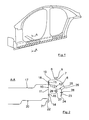
- a side section of a vehicle body 1 is shown having a Schwellerbauffle 2 according to the invention, which extends here seen in the vehicle longitudinal axis direction between an A-pillar 3 and a C-pillar 4.
- the basic structure of this Schwellerbauffle is basically the same in the area mentioned, also in the area of the connection of the A-pillar 3, a B-pillar 5 and a C-pillar 4 and is below with reference to the sectional view along the line AA Fig. 1 in conjunction with the Fig. 2 explained in more detail.
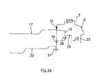
- the Fig. 2 shows a Schwellerbauffle 2 with an aluminum rocker side plate 6 as a sill side part, which is connected with a vehicle in the vertical axis direction seen upper flange first connection region 7 in a planar contact connection to a likewise approximately in the vehicle vertical axis extending flange portion 8 by means of a rivet connection 9.
- the rivet connection 9 is here preferably representative of a plurality of individual rivet connections, which are made for example by solid rivets. If this should be necessary for reasons of tightness or for reasons of strength, the flange section 8 and the first connection region 7 of the aluminum sill side plate 6 can also be additionally glued together by means of an adhesive connection, not shown here.
- the flange portion 8 is part of a hot steel sill inner panel 10 as a sill inner part, which has a flat, extending approximately in the vehicle vertical axis direction sill reinforcing member connection portion 11 to which a cross-hat-shaped steel sill reinforcement plate 12 with its angled, flange leg ends 13, 14 in abuts a flat system connection and is connected to the hot steel sill inner panel by means of a respective welded joint 15, 16.
- connection of the leg end 13 of the steel sill reinforcement plate 12 is preferably a steel bottom support 17 by means of an angled flange 18 applied flat and also connected by means of the welded joint 15 on the hot steel sill inner panel 10.
- the hot steel sill inner panel 10 is, as is known from Fig. 2 can be seen, the aluminum sill side plate 6 out folded so that at an approximately in the vehicle transverse direction extending sheet metal portion 19 of the upwardly angled flange 8 connects.
- an aluminum bottom wall 20 is furthermore connected by means of a rivet connection 21, which likewise can be formed analogously to the rivet connection 9.
- a rivet connection 21 which likewise can be formed analogously to the rivet connection 9.
- it is again preferably provided between a flange portion 22 of the aluminum bottom wall 20, which rests in a planar abutment connection to the sill reinforcement portion-connection portion 11 and just this sill reinforcement portion connecting portion 11 to provide an adhesive connection to seal the structure as a whole and a particularly high-strength connection to provide.
- the aluminum sill side plate 6 is in a, relative to the vehicle vertical axis, lower, second connection region 23 with a first U-leg 24 of a cross-sectionally U-shaped aluminum sill connection plate 25 as a sill connection part in a planar abutment connection by means of a rivet - And adhesive bond or connected by means of a laser weld 26.
- An opposite, second U-leg 27 of the aluminum rocker connecting plate 25, however, is in a flat abutment against a hat base of the steel sill reinforcing plate 12 and is firmly and tightly connected thereto by means of a rivet and adhesive connection 28.
- the aluminum side sill plate 6 is provided in the region between the two connection regions 7, 22 with an outwardly directed, convex bulge 29.
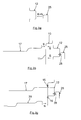
- a first method step first the aluminum rocker connecting plate 25 by means of a rivet and adhesive connection (K + N) connected to the hat-shaped steel reinforcing plate 12.
- K + N a rivet and adhesive connection
- This prefabricated assembly is then connected by means of a welded joint (S) on the hot steel sill inner panel 10, possibly simultaneously with the steel bottom support 17th
- the aluminum side sill plate 6 connected, once by a rivet and adhesive connection (K + N) in the first connection region 7 and by, for example, laser welding (LS) or by a rivet and adhesive joint welding in the second connection region 23rd
Landscapes
- Engineering & Computer Science (AREA)
- Chemical & Material Sciences (AREA)
- Combustion & Propulsion (AREA)
- Transportation (AREA)
- Mechanical Engineering (AREA)
- Architecture (AREA)
- Structural Engineering (AREA)
- Body Structure For Vehicles (AREA)
Applications Claiming Priority (1)
| Application Number | Priority Date | Filing Date | Title |
|---|---|---|---|
| DE200910058976 DE102009058976A1 (de) | 2009-12-18 | 2009-12-18 | Schwellerbaugruppe für eine Fahrzeugkarosserie sowie Verfahren zur Herstellung einer Schwellerbaugruppe |
Publications (2)
| Publication Number | Publication Date |
|---|---|
| EP2336007A1 true EP2336007A1 (fr) | 2011-06-22 |
| EP2336007B1 EP2336007B1 (fr) | 2013-09-11 |
Family
ID=43797819
Family Applications (1)
| Application Number | Title | Priority Date | Filing Date |
|---|---|---|---|
| EP20100007138 Not-in-force EP2336007B1 (fr) | 2009-12-18 | 2010-07-10 | Construction de longeron pour une carrosserie de véhicule |
Country Status (2)
| Country | Link |
|---|---|
| EP (1) | EP2336007B1 (fr) |
| DE (1) | DE102009058976A1 (fr) |
Cited By (4)
| Publication number | Priority date | Publication date | Assignee | Title |
|---|---|---|---|---|
| EP3159245A1 (fr) * | 2015-10-22 | 2017-04-26 | Constellium Singen GmbH | Structure renforcee avec un element en deux parties |
| US9776664B2 (en) | 2015-03-18 | 2017-10-03 | Honda Motor Co., Ltd. | Impact transmission structure |
| CN113165700A (zh) * | 2018-12-20 | 2021-07-23 | 宝马股份公司 | 用于汽车的侧槛梁 |
| DE102024003500A1 (de) | 2024-10-25 | 2026-04-30 | Mercedes-Benz Group AG | Baukastensystem und Verfahren zum Herstellen von unterschiedlichen Bauvarianten einer Bodenstruktur für eine Karosserie eines Personenkraftwagens |
Families Citing this family (3)
| Publication number | Priority date | Publication date | Assignee | Title |
|---|---|---|---|---|
| DE102013113164B4 (de) | 2013-11-28 | 2022-07-07 | Dr. Ing. H.C. F. Porsche Aktiengesellschaft | Schwellerbaugruppe |
| KR102440609B1 (ko) * | 2017-12-27 | 2022-09-05 | 현대자동차 주식회사 | 측방 차체 보강구조 |
| KR20220151799A (ko) * | 2021-05-07 | 2022-11-15 | 주식회사 포스코 | 차체 |
Citations (8)
| Publication number | Priority date | Publication date | Assignee | Title |
|---|---|---|---|---|
| EP1024074A1 (fr) * | 1999-01-29 | 2000-08-02 | Mazda Motor Corporation | Structure de carosserie d'un véhicule à moteur |
| EP1024073A1 (fr) * | 1999-01-29 | 2000-08-02 | Mazda Motor Corporation | Structure de carosserie de véhicule à moteur |
| DE19708215C2 (de) | 1997-02-28 | 2001-06-28 | Audi Ag | Schweller eines Kraftfahrzeugs mit einer Verstärkungseinlage |
| JP2006264476A (ja) * | 2005-03-23 | 2006-10-05 | Kobe Steel Ltd | 自動車パネル構造体 |
| DE102005043698A1 (de) * | 2005-09-14 | 2007-03-15 | Daimlerchrysler Ag | Seitenschweller einer Kraftwagenkarosserie |
| EP1840003A2 (fr) * | 2006-03-31 | 2007-10-03 | Dr.Ing.h.c. F. Porsche Aktiengesellschaft | Elément de renforcement d'un soubassement de porte de carrosserie de véhicule automobile |
| EP2014539A1 (fr) * | 2007-07-11 | 2009-01-14 | Dr.Ing. h.c.F. Porsche Aktiengesellschaft | Carrosserie de véhicule automobile dotée de longerons latéraux |
| DE102008020081A1 (de) | 2008-04-22 | 2009-10-29 | Dr. Ing. H.C. F. Porsche Aktiengesellschaft | Schweller |
Family Cites Families (1)
| Publication number | Priority date | Publication date | Assignee | Title |
|---|---|---|---|---|
| DE102005038463A1 (de) * | 2005-08-13 | 2007-02-15 | Daimlerchrysler Ag | Träger einer Kraftwagenkarosserie |
-
2009
- 2009-12-18 DE DE200910058976 patent/DE102009058976A1/de not_active Withdrawn
-
2010
- 2010-07-10 EP EP20100007138 patent/EP2336007B1/fr not_active Not-in-force
Patent Citations (8)
| Publication number | Priority date | Publication date | Assignee | Title |
|---|---|---|---|---|
| DE19708215C2 (de) | 1997-02-28 | 2001-06-28 | Audi Ag | Schweller eines Kraftfahrzeugs mit einer Verstärkungseinlage |
| EP1024074A1 (fr) * | 1999-01-29 | 2000-08-02 | Mazda Motor Corporation | Structure de carosserie d'un véhicule à moteur |
| EP1024073A1 (fr) * | 1999-01-29 | 2000-08-02 | Mazda Motor Corporation | Structure de carosserie de véhicule à moteur |
| JP2006264476A (ja) * | 2005-03-23 | 2006-10-05 | Kobe Steel Ltd | 自動車パネル構造体 |
| DE102005043698A1 (de) * | 2005-09-14 | 2007-03-15 | Daimlerchrysler Ag | Seitenschweller einer Kraftwagenkarosserie |
| EP1840003A2 (fr) * | 2006-03-31 | 2007-10-03 | Dr.Ing.h.c. F. Porsche Aktiengesellschaft | Elément de renforcement d'un soubassement de porte de carrosserie de véhicule automobile |
| EP2014539A1 (fr) * | 2007-07-11 | 2009-01-14 | Dr.Ing. h.c.F. Porsche Aktiengesellschaft | Carrosserie de véhicule automobile dotée de longerons latéraux |
| DE102008020081A1 (de) | 2008-04-22 | 2009-10-29 | Dr. Ing. H.C. F. Porsche Aktiengesellschaft | Schweller |
Cited By (5)
| Publication number | Priority date | Publication date | Assignee | Title |
|---|---|---|---|---|
| US9776664B2 (en) | 2015-03-18 | 2017-10-03 | Honda Motor Co., Ltd. | Impact transmission structure |
| EP3159245A1 (fr) * | 2015-10-22 | 2017-04-26 | Constellium Singen GmbH | Structure renforcee avec un element en deux parties |
| CN113165700A (zh) * | 2018-12-20 | 2021-07-23 | 宝马股份公司 | 用于汽车的侧槛梁 |
| CN113165700B (zh) * | 2018-12-20 | 2023-10-03 | 宝马股份公司 | 用于汽车的侧槛梁、模块化系统和方法 |
| DE102024003500A1 (de) | 2024-10-25 | 2026-04-30 | Mercedes-Benz Group AG | Baukastensystem und Verfahren zum Herstellen von unterschiedlichen Bauvarianten einer Bodenstruktur für eine Karosserie eines Personenkraftwagens |
Also Published As
| Publication number | Publication date |
|---|---|
| DE102009058976A1 (de) | 2011-06-22 |
| EP2336007B1 (fr) | 2013-09-11 |
Similar Documents
| Publication | Publication Date | Title |
|---|---|---|
| EP2535241B1 (fr) | Structure de longeron pour châssis de véhicules utilitaires, notamment de camions et/ou de bus | |
| EP1840003B1 (fr) | Elément de renforcement d'un soubassement de porte de carrosserie de véhicule automobile | |
| EP2336007B1 (fr) | Construction de longeron pour une carrosserie de véhicule | |
| DE19708215C2 (de) | Schweller eines Kraftfahrzeugs mit einer Verstärkungseinlage | |
| EP2137048B1 (fr) | Composant de carrosserie pour un véhicule automobile | |
| WO2012007346A1 (fr) | Renfort de pied milieu d'un véhicule automobile | |
| EP4035951B1 (fr) | Dispositif pare-chocs pour un véhicule automobile | |
| EP4035952B1 (fr) | Agencement de pare-chocs pourvu de support supplémentaire | |
| EP2357120B1 (fr) | Structure de support d'une carrosserie de véhicule dans la zone du côté du rail d'un montant C | |
| DE202021103263U1 (de) | Stoßfängeranordnung mit zusätzlicher Abstützung | |
| WO2018060143A1 (fr) | Élément structural pour une carrosserie de véhicule automobile | |
| WO2011032715A1 (fr) | Structure de carrosserie de véhicule située dans la zone du plancher de l'habitacle et procédé de fabrication associé | |
| EP1569838A1 (fr) | Module paroi laterale pour un vehicule automobile et procede de fabrication pour une carrosserie automobile | |
| DE19852976B4 (de) | Türrahmen für einen Personenkraftwagen | |
| DE102014114348A1 (de) | Tragrahmenstruktur und Verfahren zur Herstellung einer Tragrahmenstruktur für ein Kraftfahrzeug | |
| DE102009021964A1 (de) | Hohlprofil für eine Fahrzeugkarosserie | |
| DE102007018458B4 (de) | Karosseriebauteil für einen Kraftwagen und Verfahren zu dessen Herstellung | |
| DE10357907B4 (de) | Türsäule für eine Tragrahmenstruktur | |
| DE102015000979B3 (de) | Rahmenelement, insbesondere Seitenwandrahmenelement, für eine Fahrzeugkarosserie sowie Verfahren zur Herstellung eines Rahmenelementes für eine Fahrzeugkarosserie | |
| EP1357017B1 (fr) | Chassis de véhicule en treillis | |
| WO2013041177A1 (fr) | Partie de cadre de toit d'une carrosserie de véhicule automobile | |
| DE102010064591B3 (de) | Querträgeranordnung, insbesondere Fersenblechanordnung, in einer Fahrzeugkarosserie | |
| DE102004013511A1 (de) | Karosseriesäule | |
| DE102009030432A1 (de) | Hybridzusammenbau für einen Kraftwagen und Verfahren zu dessen Herstellung | |
| DE102008027199A1 (de) | Queraussteifung für ein Kraftfahrzeug |
Legal Events
| Date | Code | Title | Description |
|---|---|---|---|
| PUAI | Public reference made under article 153(3) epc to a published international application that has entered the european phase |
Free format text: ORIGINAL CODE: 0009012 |
|
| AK | Designated contracting states |
Kind code of ref document: A1 Designated state(s): AL AT BE BG CH CY CZ DE DK EE ES FI FR GB GR HR HU IE IS IT LI LT LU LV MC MK MT NL NO PL PT RO SE SI SK SM TR |
|
| AX | Request for extension of the european patent |
Extension state: BA ME RS |
|
| 17P | Request for examination filed |
Effective date: 20111222 |
|
| RIC1 | Information provided on ipc code assigned before grant |
Ipc: B62D 21/15 20060101AFI20130108BHEP Ipc: B62D 29/00 20060101ALI20130108BHEP Ipc: B62D 25/02 20060101ALI20130108BHEP |
|
| GRAP | Despatch of communication of intention to grant a patent |
Free format text: ORIGINAL CODE: EPIDOSNIGR1 |
|
| INTG | Intention to grant announced |
Effective date: 20130425 |
|
| RIN1 | Information on inventor provided before grant (corrected) |
Inventor name: WEIGL, WILLI Inventor name: CARLE, KLAUS-DIETER Inventor name: RUESS, MARCO |
|
| GRAS | Grant fee paid |
Free format text: ORIGINAL CODE: EPIDOSNIGR3 |
|
| GRAA | (expected) grant |
Free format text: ORIGINAL CODE: 0009210 |
|
| AK | Designated contracting states |
Kind code of ref document: B1 Designated state(s): AL AT BE BG CH CY CZ DE DK EE ES FI FR GB GR HR HU IE IS IT LI LT LU LV MC MK MT NL NO PL PT RO SE SI SK SM TR |
|
| REG | Reference to a national code |
Ref country code: GB Ref legal event code: FG4D Free format text: NOT ENGLISH |
|
| REG | Reference to a national code |
Ref country code: CH Ref legal event code: EP |
|
| REG | Reference to a national code |
Ref country code: AT Ref legal event code: REF Ref document number: 631459 Country of ref document: AT Kind code of ref document: T Effective date: 20130915 |
|
| REG | Reference to a national code |
Ref country code: IE Ref legal event code: FG4D Free format text: LANGUAGE OF EP DOCUMENT: GERMAN |
|
| REG | Reference to a national code |
Ref country code: DE Ref legal event code: R096 Ref document number: 502010004666 Country of ref document: DE Effective date: 20131107 |
|
| PG25 | Lapsed in a contracting state [announced via postgrant information from national office to epo] |
Ref country code: SE Free format text: LAPSE BECAUSE OF FAILURE TO SUBMIT A TRANSLATION OF THE DESCRIPTION OR TO PAY THE FEE WITHIN THE PRESCRIBED TIME-LIMIT Effective date: 20130911 Ref country code: CY Free format text: LAPSE BECAUSE OF FAILURE TO SUBMIT A TRANSLATION OF THE DESCRIPTION OR TO PAY THE FEE WITHIN THE PRESCRIBED TIME-LIMIT Effective date: 20130724 Ref country code: NO Free format text: LAPSE BECAUSE OF FAILURE TO SUBMIT A TRANSLATION OF THE DESCRIPTION OR TO PAY THE FEE WITHIN THE PRESCRIBED TIME-LIMIT Effective date: 20131211 Ref country code: LT Free format text: LAPSE BECAUSE OF FAILURE TO SUBMIT A TRANSLATION OF THE DESCRIPTION OR TO PAY THE FEE WITHIN THE PRESCRIBED TIME-LIMIT Effective date: 20130911 Ref country code: HR Free format text: LAPSE BECAUSE OF FAILURE TO SUBMIT A TRANSLATION OF THE DESCRIPTION OR TO PAY THE FEE WITHIN THE PRESCRIBED TIME-LIMIT Effective date: 20130911 |
|
| REG | Reference to a national code |
Ref country code: NL Ref legal event code: VDEP Effective date: 20130911 |
|
| REG | Reference to a national code |
Ref country code: LT Ref legal event code: MG4D |
|
| PG25 | Lapsed in a contracting state [announced via postgrant information from national office to epo] |
Ref country code: FI Free format text: LAPSE BECAUSE OF FAILURE TO SUBMIT A TRANSLATION OF THE DESCRIPTION OR TO PAY THE FEE WITHIN THE PRESCRIBED TIME-LIMIT Effective date: 20130911 Ref country code: LV Free format text: LAPSE BECAUSE OF FAILURE TO SUBMIT A TRANSLATION OF THE DESCRIPTION OR TO PAY THE FEE WITHIN THE PRESCRIBED TIME-LIMIT Effective date: 20130911 Ref country code: SI Free format text: LAPSE BECAUSE OF FAILURE TO SUBMIT A TRANSLATION OF THE DESCRIPTION OR TO PAY THE FEE WITHIN THE PRESCRIBED TIME-LIMIT Effective date: 20130911 Ref country code: GR Free format text: LAPSE BECAUSE OF FAILURE TO SUBMIT A TRANSLATION OF THE DESCRIPTION OR TO PAY THE FEE WITHIN THE PRESCRIBED TIME-LIMIT Effective date: 20131212 |
|
| PG25 | Lapsed in a contracting state [announced via postgrant information from national office to epo] |
Ref country code: CY Free format text: LAPSE BECAUSE OF FAILURE TO SUBMIT A TRANSLATION OF THE DESCRIPTION OR TO PAY THE FEE WITHIN THE PRESCRIBED TIME-LIMIT Effective date: 20130911 |
|
| PG25 | Lapsed in a contracting state [announced via postgrant information from national office to epo] |
Ref country code: NL Free format text: LAPSE BECAUSE OF FAILURE TO SUBMIT A TRANSLATION OF THE DESCRIPTION OR TO PAY THE FEE WITHIN THE PRESCRIBED TIME-LIMIT Effective date: 20130911 Ref country code: RO Free format text: LAPSE BECAUSE OF FAILURE TO SUBMIT A TRANSLATION OF THE DESCRIPTION OR TO PAY THE FEE WITHIN THE PRESCRIBED TIME-LIMIT Effective date: 20130911 Ref country code: SK Free format text: LAPSE BECAUSE OF FAILURE TO SUBMIT A TRANSLATION OF THE DESCRIPTION OR TO PAY THE FEE WITHIN THE PRESCRIBED TIME-LIMIT Effective date: 20130911 Ref country code: IS Free format text: LAPSE BECAUSE OF FAILURE TO SUBMIT A TRANSLATION OF THE DESCRIPTION OR TO PAY THE FEE WITHIN THE PRESCRIBED TIME-LIMIT Effective date: 20140111 Ref country code: EE Free format text: LAPSE BECAUSE OF FAILURE TO SUBMIT A TRANSLATION OF THE DESCRIPTION OR TO PAY THE FEE WITHIN THE PRESCRIBED TIME-LIMIT Effective date: 20130911 Ref country code: CZ Free format text: LAPSE BECAUSE OF FAILURE TO SUBMIT A TRANSLATION OF THE DESCRIPTION OR TO PAY THE FEE WITHIN THE PRESCRIBED TIME-LIMIT Effective date: 20130911 |
|
| PG25 | Lapsed in a contracting state [announced via postgrant information from national office to epo] |
Ref country code: ES Free format text: LAPSE BECAUSE OF FAILURE TO SUBMIT A TRANSLATION OF THE DESCRIPTION OR TO PAY THE FEE WITHIN THE PRESCRIBED TIME-LIMIT Effective date: 20130911 Ref country code: PL Free format text: LAPSE BECAUSE OF FAILURE TO SUBMIT A TRANSLATION OF THE DESCRIPTION OR TO PAY THE FEE WITHIN THE PRESCRIBED TIME-LIMIT Effective date: 20130911 |
|
| REG | Reference to a national code |
Ref country code: DE Ref legal event code: R097 Ref document number: 502010004666 Country of ref document: DE |
|
| PG25 | Lapsed in a contracting state [announced via postgrant information from national office to epo] |
Ref country code: PT Free format text: LAPSE BECAUSE OF FAILURE TO SUBMIT A TRANSLATION OF THE DESCRIPTION OR TO PAY THE FEE WITHIN THE PRESCRIBED TIME-LIMIT Effective date: 20140113 |
|
| PLBE | No opposition filed within time limit |
Free format text: ORIGINAL CODE: 0009261 |
|
| STAA | Information on the status of an ep patent application or granted ep patent |
Free format text: STATUS: NO OPPOSITION FILED WITHIN TIME LIMIT |
|
| 26N | No opposition filed |
Effective date: 20140612 |
|
| PG25 | Lapsed in a contracting state [announced via postgrant information from national office to epo] |
Ref country code: IT Free format text: LAPSE BECAUSE OF FAILURE TO SUBMIT A TRANSLATION OF THE DESCRIPTION OR TO PAY THE FEE WITHIN THE PRESCRIBED TIME-LIMIT Effective date: 20130911 |
|
| REG | Reference to a national code |
Ref country code: DE Ref legal event code: R097 Ref document number: 502010004666 Country of ref document: DE Effective date: 20140612 |
|
| PG25 | Lapsed in a contracting state [announced via postgrant information from national office to epo] |
Ref country code: DK Free format text: LAPSE BECAUSE OF FAILURE TO SUBMIT A TRANSLATION OF THE DESCRIPTION OR TO PAY THE FEE WITHIN THE PRESCRIBED TIME-LIMIT Effective date: 20130911 |
|
| PG25 | Lapsed in a contracting state [announced via postgrant information from national office to epo] |
Ref country code: LU Free format text: LAPSE BECAUSE OF FAILURE TO SUBMIT A TRANSLATION OF THE DESCRIPTION OR TO PAY THE FEE WITHIN THE PRESCRIBED TIME-LIMIT Effective date: 20140710 |
|
| REG | Reference to a national code |
Ref country code: CH Ref legal event code: PL |
|
| REG | Reference to a national code |
Ref country code: IE Ref legal event code: MM4A |
|
| PG25 | Lapsed in a contracting state [announced via postgrant information from national office to epo] |
Ref country code: CH Free format text: LAPSE BECAUSE OF NON-PAYMENT OF DUE FEES Effective date: 20140731 Ref country code: LI Free format text: LAPSE BECAUSE OF NON-PAYMENT OF DUE FEES Effective date: 20140731 |
|
| PG25 | Lapsed in a contracting state [announced via postgrant information from national office to epo] |
Ref country code: IE Free format text: LAPSE BECAUSE OF NON-PAYMENT OF DUE FEES Effective date: 20140710 |
|
| PG25 | Lapsed in a contracting state [announced via postgrant information from national office to epo] |
Ref country code: SM Free format text: LAPSE BECAUSE OF FAILURE TO SUBMIT A TRANSLATION OF THE DESCRIPTION OR TO PAY THE FEE WITHIN THE PRESCRIBED TIME-LIMIT Effective date: 20130911 Ref country code: MC Free format text: LAPSE BECAUSE OF FAILURE TO SUBMIT A TRANSLATION OF THE DESCRIPTION OR TO PAY THE FEE WITHIN THE PRESCRIBED TIME-LIMIT Effective date: 20130911 |
|
| PG25 | Lapsed in a contracting state [announced via postgrant information from national office to epo] |
Ref country code: BG Free format text: LAPSE BECAUSE OF FAILURE TO SUBMIT A TRANSLATION OF THE DESCRIPTION OR TO PAY THE FEE WITHIN THE PRESCRIBED TIME-LIMIT Effective date: 20130911 Ref country code: MT Free format text: LAPSE BECAUSE OF FAILURE TO SUBMIT A TRANSLATION OF THE DESCRIPTION OR TO PAY THE FEE WITHIN THE PRESCRIBED TIME-LIMIT Effective date: 20130911 |
|
| REG | Reference to a national code |
Ref country code: FR Ref legal event code: PLFP Year of fee payment: 7 |
|
| PG25 | Lapsed in a contracting state [announced via postgrant information from national office to epo] |
Ref country code: BE Free format text: LAPSE BECAUSE OF FAILURE TO SUBMIT A TRANSLATION OF THE DESCRIPTION OR TO PAY THE FEE WITHIN THE PRESCRIBED TIME-LIMIT Effective date: 20140731 Ref country code: TR Free format text: LAPSE BECAUSE OF FAILURE TO SUBMIT A TRANSLATION OF THE DESCRIPTION OR TO PAY THE FEE WITHIN THE PRESCRIBED TIME-LIMIT Effective date: 20130911 Ref country code: HU Free format text: LAPSE BECAUSE OF FAILURE TO SUBMIT A TRANSLATION OF THE DESCRIPTION OR TO PAY THE FEE WITHIN THE PRESCRIBED TIME-LIMIT; INVALID AB INITIO Effective date: 20100710 |
|
| REG | Reference to a national code |
Ref country code: AT Ref legal event code: MM01 Ref document number: 631459 Country of ref document: AT Kind code of ref document: T Effective date: 20150710 |
|
| PG25 | Lapsed in a contracting state [announced via postgrant information from national office to epo] |
Ref country code: AT Free format text: LAPSE BECAUSE OF NON-PAYMENT OF DUE FEES Effective date: 20150710 |
|
| REG | Reference to a national code |
Ref country code: FR Ref legal event code: PLFP Year of fee payment: 8 |
|
| PG25 | Lapsed in a contracting state [announced via postgrant information from national office to epo] |
Ref country code: MK Free format text: LAPSE BECAUSE OF FAILURE TO SUBMIT A TRANSLATION OF THE DESCRIPTION OR TO PAY THE FEE WITHIN THE PRESCRIBED TIME-LIMIT Effective date: 20130911 |
|
| REG | Reference to a national code |
Ref country code: DE Ref legal event code: R084 Ref document number: 502010004666 Country of ref document: DE |
|
| REG | Reference to a national code |
Ref country code: FR Ref legal event code: PLFP Year of fee payment: 9 |
|
| PG25 | Lapsed in a contracting state [announced via postgrant information from national office to epo] |
Ref country code: AL Free format text: LAPSE BECAUSE OF FAILURE TO SUBMIT A TRANSLATION OF THE DESCRIPTION OR TO PAY THE FEE WITHIN THE PRESCRIBED TIME-LIMIT Effective date: 20130911 |
|
| PGFP | Annual fee paid to national office [announced via postgrant information from national office to epo] |
Ref country code: FR Payment date: 20180724 Year of fee payment: 9 Ref country code: DE Payment date: 20180731 Year of fee payment: 9 |
|
| PGFP | Annual fee paid to national office [announced via postgrant information from national office to epo] |
Ref country code: GB Payment date: 20180724 Year of fee payment: 9 |
|
| REG | Reference to a national code |
Ref country code: DE Ref legal event code: R119 Ref document number: 502010004666 Country of ref document: DE |
|
| GBPC | Gb: european patent ceased through non-payment of renewal fee |
Effective date: 20190710 |
|
| PG25 | Lapsed in a contracting state [announced via postgrant information from national office to epo] |
Ref country code: GB Free format text: LAPSE BECAUSE OF NON-PAYMENT OF DUE FEES Effective date: 20190710 Ref country code: DE Free format text: LAPSE BECAUSE OF NON-PAYMENT OF DUE FEES Effective date: 20200201 |
|
| PG25 | Lapsed in a contracting state [announced via postgrant information from national office to epo] |
Ref country code: FR Free format text: LAPSE BECAUSE OF NON-PAYMENT OF DUE FEES Effective date: 20190731 |