EP2336032A1 - Dispositif d emballage de médicaments - Google Patents
Dispositif d emballage de médicaments Download PDFInfo
- Publication number
- EP2336032A1 EP2336032A1 EP09817420A EP09817420A EP2336032A1 EP 2336032 A1 EP2336032 A1 EP 2336032A1 EP 09817420 A EP09817420 A EP 09817420A EP 09817420 A EP09817420 A EP 09817420A EP 2336032 A1 EP2336032 A1 EP 2336032A1
- Authority
- EP
- European Patent Office
- Prior art keywords
- package sheet
- section
- medicine
- conveying direction
- unfolding guide
- Prior art date
- Legal status (The legal status is an assumption and is not a legal conclusion. Google has not performed a legal analysis and makes no representation as to the accuracy of the status listed.)
- Granted
Links
Images















Classifications
-
- B—PERFORMING OPERATIONS; TRANSPORTING
- B65—CONVEYING; PACKING; STORING; HANDLING THIN OR FILAMENTARY MATERIAL
- B65B—MACHINES, APPARATUS OR DEVICES FOR, OR METHODS OF, PACKAGING ARTICLES OR MATERIALS; UNPACKING
- B65B51/00—Devices for, or methods of, sealing or securing package folds or closures; Devices for gathering or twisting wrappers, or necks of bags
- B65B51/10—Applying or generating heat or pressure or combinations thereof
- B65B51/26—Devices specially adapted for producing transverse or longitudinal seams in webs or tubes
- B65B51/28—Rollers for producing longitudinal and transverse seams simultaneously
-
- B—PERFORMING OPERATIONS; TRANSPORTING
- B65—CONVEYING; PACKING; STORING; HANDLING THIN OR FILAMENTARY MATERIAL
- B65B—MACHINES, APPARATUS OR DEVICES FOR, OR METHODS OF, PACKAGING ARTICLES OR MATERIALS; UNPACKING
- B65B9/00—Enclosing successive articles, or quantities of material, e.g. liquids or semiliquids, in flat, folded, or tubular webs of flexible sheet material; Subdividing filled flexible tubes to form packages
- B65B9/06—Enclosing successive articles, or quantities of material, in a longitudinally-folded web, or in a web folded into a tube about the articles or quantities of material placed upon it
-
- B—PERFORMING OPERATIONS; TRANSPORTING
- B65—CONVEYING; PACKING; STORING; HANDLING THIN OR FILAMENTARY MATERIAL
- B65B—MACHINES, APPARATUS OR DEVICES FOR, OR METHODS OF, PACKAGING ARTICLES OR MATERIALS; UNPACKING
- B65B1/00—Packaging fluent solid material, e.g. powders, granular or loose fibrous material, loose masses of small articles, in individual containers or receptacles, e.g. bags, sacks, boxes, cartons, cans, or jars
- B65B1/30—Devices or methods for controlling or determining the quantity or quality or the material fed or filled
-
- B—PERFORMING OPERATIONS; TRANSPORTING
- B65—CONVEYING; PACKING; STORING; HANDLING THIN OR FILAMENTARY MATERIAL
- B65B—MACHINES, APPARATUS OR DEVICES FOR, OR METHODS OF, PACKAGING ARTICLES OR MATERIALS; UNPACKING
- B65B39/00—Nozzles, funnels or guides for introducing articles or materials into containers or wrappers
-
- B—PERFORMING OPERATIONS; TRANSPORTING
- B65—CONVEYING; PACKING; STORING; HANDLING THIN OR FILAMENTARY MATERIAL
- B65B—MACHINES, APPARATUS OR DEVICES FOR, OR METHODS OF, PACKAGING ARTICLES OR MATERIALS; UNPACKING
- B65B5/00—Packaging individual articles in containers or receptacles, e.g. bags, sacks, boxes, cartons, cans, jars
- B65B5/10—Filling containers or receptacles progressively or in stages by introducing successive articles, or layers of articles
- B65B5/101—Filling containers or receptacles progressively or in stages by introducing successive articles, or layers of articles by gravity
- B65B5/103—Filling containers or receptacles progressively or in stages by introducing successive articles, or layers of articles by gravity for packaging pills or tablets
-
- B—PERFORMING OPERATIONS; TRANSPORTING
- B65—CONVEYING; PACKING; STORING; HANDLING THIN OR FILAMENTARY MATERIAL
- B65B—MACHINES, APPARATUS OR DEVICES FOR, OR METHODS OF, PACKAGING ARTICLES OR MATERIALS; UNPACKING
- B65B51/00—Devices for, or methods of, sealing or securing package folds or closures; Devices for gathering or twisting wrappers, or necks of bags
- B65B51/10—Applying or generating heat or pressure or combinations thereof
- B65B51/16—Applying or generating heat or pressure or combinations thereof by rotary members
-
- B—PERFORMING OPERATIONS; TRANSPORTING
- B65—CONVEYING; PACKING; STORING; HANDLING THIN OR FILAMENTARY MATERIAL
- B65B—MACHINES, APPARATUS OR DEVICES FOR, OR METHODS OF, PACKAGING ARTICLES OR MATERIALS; UNPACKING
- B65B61/00—Auxiliary devices, not otherwise provided for, for operating on sheets, blanks, webs, binding material, containers or packages
- B65B61/02—Auxiliary devices, not otherwise provided for, for operating on sheets, blanks, webs, binding material, containers or packages for perforating, scoring, slitting, or applying code or date marks on material prior to packaging
-
- B—PERFORMING OPERATIONS; TRANSPORTING
- B65—CONVEYING; PACKING; STORING; HANDLING THIN OR FILAMENTARY MATERIAL
- B65B—MACHINES, APPARATUS OR DEVICES FOR, OR METHODS OF, PACKAGING ARTICLES OR MATERIALS; UNPACKING
- B65B61/00—Auxiliary devices, not otherwise provided for, for operating on sheets, blanks, webs, binding material, containers or packages
- B65B61/02—Auxiliary devices, not otherwise provided for, for operating on sheets, blanks, webs, binding material, containers or packages for perforating, scoring, slitting, or applying code or date marks on material prior to packaging
- B65B61/025—Auxiliary devices, not otherwise provided for, for operating on sheets, blanks, webs, binding material, containers or packages for perforating, scoring, slitting, or applying code or date marks on material prior to packaging for applying, e.g. printing, code or date marks on material prior to packaging
-
- B—PERFORMING OPERATIONS; TRANSPORTING
- B65—CONVEYING; PACKING; STORING; HANDLING THIN OR FILAMENTARY MATERIAL
- B65B—MACHINES, APPARATUS OR DEVICES FOR, OR METHODS OF, PACKAGING ARTICLES OR MATERIALS; UNPACKING
- B65B9/00—Enclosing successive articles, or quantities of material, e.g. liquids or semiliquids, in flat, folded, or tubular webs of flexible sheet material; Subdividing filled flexible tubes to form packages
- B65B9/06—Enclosing successive articles, or quantities of material, in a longitudinally-folded web, or in a web folded into a tube about the articles or quantities of material placed upon it
- B65B9/067—Enclosing successive articles, or quantities of material, in a longitudinally-folded web, or in a web folded into a tube about the articles or quantities of material placed upon it the web advancing continuously
-
- B—PERFORMING OPERATIONS; TRANSPORTING
- B65—CONVEYING; PACKING; STORING; HANDLING THIN OR FILAMENTARY MATERIAL
- B65B—MACHINES, APPARATUS OR DEVICES FOR, OR METHODS OF, PACKAGING ARTICLES OR MATERIALS; UNPACKING
- B65B1/00—Packaging fluent solid material, e.g. powders, granular or loose fibrous material, loose masses of small articles, in individual containers or receptacles, e.g. bags, sacks, boxes, cartons, cans, or jars
- B65B1/20—Reducing volume of filled material
- B65B1/22—Reducing volume of filled material by vibration
-
- B—PERFORMING OPERATIONS; TRANSPORTING
- B65—CONVEYING; PACKING; STORING; HANDLING THIN OR FILAMENTARY MATERIAL
- B65B—MACHINES, APPARATUS OR DEVICES FOR, OR METHODS OF, PACKAGING ARTICLES OR MATERIALS; UNPACKING
- B65B43/00—Forming, feeding, opening or setting-up containers or receptacles in association with packaging
- B65B43/04—Forming flat bags from webs
Definitions
- the present invention relates to a medicine packaging apparatus for packaging medicine such as a tablet including a capsule tablet and powdered medicine.
- Various medicine packaging apparatuses have been provided which prepare continuous medicine bags or dose packages by packaging medicine such as a tablet and powdered medicine per dose (as one medicine bags) based on prescriptions.
- Some of these devices use package sheet rolls on which a long and narrow package sheet previously folded into two in the longitudinal direction is wound.
- a packaging section of this kind of medicine packaging apparatus a package sheet is fed from the roll, and required information is printed thereon by a printing section.
- the package sheet is then unfolded from the folded state to be opened, and a nozzle section of a hopper is inserted into the opening to introduce one dose of the medicine.
- the package sheet is sealed (heat-sealed) in a heat sealing section so that the medicine is enclosed (see, e.g., Patent Documents 1 to 4).
- a length of the package sheet from the printing section to the heat sealing section functions only for the routing, i.e., the length is not used for medicine packaging and therefore should be discarded, which is not desirable in view of cost.
- the long path of the package sheet from the printing section to the heat sealing section hinders downsizing of the medicine packaging apparatus.
- a two-folded package sheet 1100 is expanded into V shape by an unfolding guide 1106, and reaches a heating roller 102 of a heat sealing section via a nozzle section 1101 of a hopper.
- the heater roller 102 has a horizontal seal 1103 which seals an opening edge of the package sheet 1100 in the longitudinal direction, and a vertical seal 1104 which seals the package sheet 1100 crosswise from the opening edge to a crease of the package sheet 1100.
- the tension applied to the two portions of the two-folded sheet 1100 is unbalanced during application of the vertical seal 1104, one of the portions of the two-folded sheet 1100 sags against the other portion, which tends to generate wrinkles 1105 extending in the longitudinal direction near the horizontal seal 1103.
- the wrinkles 1105 are assumed to be attributed to such causes as a bulge of the package sheet 1100 generated in putting medicine therein and a difference of tension between the portions of the package sheet 1100 where the horizontal seal 1103 is formed and where the vertical seal 1104 is formed.
- Such wrinkles 1105 result in poor airtightness due to sealing failure and thereby cause mixture (contamination) of the medicine between adjacent prescriptions.
- Patent Documents 1, 2 disclose an unfolding guide 1106 in the shape of a triangular plate with a constant thickness and an unfolding guide 1106 constituted of a plurality of flat planes and having an outline of a generally triangular pyramid shape.
- the unfolding guides 1106 in such shapes are employed and placed in the vicinity of the printing section to shorten the path length from the printing section to the heat sealing section, the above-mentioned wrinkles 1105 are unavoidably generated on the package sheet 1100.
- An object of the present invention is provide a medicine packaging device having a shortened distance from a printing section to a heat sealing section without generating wrinkles on package sheets.
- the present invention provides a medicine packaging apparatus, comprising: a sheet supply section for unrolling and feeding an elongated package sheet from a roll on which the package sheet is wound, the package sheet previously being folded along its longitudinal direction into two portions; a printing section for making a print on the package sheet fed from the sheet supply section; a curvature guide for curving a conveying direction of the package sheet having passed the printing section; an unfolding guide arranged on a downstream side of the curvature guide in the conveying direction of the package sheet, the unfolding guide being for unfolding and opening the two-folded package sheet; a medicine introducing section arranged on the downstream side of the unfolding guide in the conveying direction of the package sheet, the medicine introducing section being for introducing a medicine into an opening of the package sheet; and a heat sealing section arranged on the downstream side of the medicine introducing section in the conveying direction of the package sheet, the heat sealing section being for sealing the package sheet so as to enclose the introduced medicine, wherein the unfolding guide comprises: a main
- the unfolding guide is provided with the pair of unfolding guide surfaces which are convex curved surfaces stretching from the main ridge. Since the two-folded package sheet is guided with the pair of unfolding guide surfaces and thereby gently deformed or unfolded while being smoothly fed to the heat sealing section so that an opening can be formed. Therefore, even if the printing section, the unfolding guide, and the heat sealing section are placed in the vicinity of each other, it becomes possible to prevent wrinkles from being generated on the package sheet in the heat sealing section.
- the shape of the unfolding guide enables the printing section, the curvature guide, the unfolding guide, the medicine introducing section, and the printing section to be placed in the vicinity of each other so as to reduce a distance from the printing section to the heat sealing section without generating the wrinkles on the package sheet.
- the length of the useless package sheet used only for routing upon the initial startup of the medicine packaging apparatus or at the time of roll replacement and not for packaging of the medicine can be reduced to the minimum, and thereby running cost reduction can be achieved.
- downsizing of the device can be attained by reducing the distance from the printing section to the heat sealing section.
- the contact start position with the package sheet of the unfolding guide surface on the outer side of the curve in the conveying direction is located on the upstream side in the conveying direction of the contact start position with the package sheet of the unfolding guide surface on the inner side of the curve.
- a distance between the pair of unfolding guide surfaces increases as the unfolding guide surfaces are farther away from the main ridge, and wherein, seen from the direction facing the main ridge, the distance between the unfolding guide surfaces becomes narrower from the upstream side to the downstream side in the conveying direction.
- each of the unfolding guide surfaces includes: a rear end edge gradually coming close to the main ridge from the upstream side to the downstream side in the conveying direction of the package sheet, the rear end edge being jointed to an end section of the main ridge on the downstream side in the conveying direction of the package sheet; and a first concave section formed in a portion ranging from a position spaced from the main ridge to the rear end edge in a region between a position spaced from the contact start positions on the downstream side in the conveying direction of the package sheet and the end section on the downstream side.
- the two-folded package sheet When the medicine is introduced into the opening of the two-folded package sheet from the medicine introducing section on the downstream side of the unfolding guide, the two-folded package sheet is bulged in accordance with the volume of the medicine (a distance between the two portions of the two-folded package sheet is stretched). Particularly when the volume of the medicine to be introduced is large, the bulge of this package sheet is notable.
- the first concave section provided in the unfolding guide surface when the package sheet is bulged in accordance with the introduction of the medicine, the package sheet comes into close contact with the first concave section of the unfolding guide surface, and an amount of the package sheet corresponding to this close contact is fed to a portion on the downstream side of the unfolding guide into which the medicine is introduced.
- the package sheet can be unfolded in a state that some margins are left for the bulge of the package sheet in accordance with the introduction of the medicine (a state that the bulge can be "absorbed"), so that the opening can be formed. Thereby, it becomes possible to more reliably prevent the wrinkles from being generated in the heat sealing section.
- the package sheet Since the package sheet has the margins for the bulge due to the first concave section, the package sheet can ease a shock received from the medicine introduced from the medicine introducing section. By this shock easing, it becomes possible to prevent the medicine (powdered medicine in particular) from being blown up in the two-folded package sheet.
- each of the unfolding guide surfaces includes a second concave section formed on the downstream side of the first concave section in the conveying direction of the package sheet in a region including the end section of the main ridge on the downstream side.
- the package sheet comes into close contact with the second concave section, and an amount of the package sheet corresponding to this close contact is fed to the portion on the downstream side of the unfolding guide into which the medicine is introduced. That is, by providing the second concave section in addition to the first concave section, a margin amount for the bulge of the package sheet in accordance with the introduction of the medicine is increased.
- an area of the second concave section of the unfolding guide surface located on the outer side of the curve in the conveying direction made by the curvature guide relative to the main ridge is larger than an area of the second concave section of the unfolding guide surface located on the inner side of the curve in the conveying direction made by the curvature guide relative to the main ridge.
- a linear projection extending in the direction crossing the main ridge may be provided at a position adjacent to the contact start position of the unfolding guide surface located on the outer side of the curve in the conveying direction by the curvature guide relative to the main ridge.
- a bulge amount of the unfolding guide surface located on the inner side of the curve in the conveying direction by the curvature guide relative to the main ridge is larger than a bulge amount at the contact start position of the unfolding guide surface located on the outer side of the curve in the conveying direction by the curvature guide relative to the main ridge.
- the tension applied to the portion of the two-folded package sheet on the inner side of the curve tends to be smaller than the tension applied to the portion on the outer side of the curve.
- the unfolding guide further comprises: a sub ridge extending from an end section of the main ridge on the upstream side in the conveying direction of the package sheet to the upstream side in the conveying direction of the package sheet; and a pair of top surfaces which are convex curved surfaces stretching from the sub ridge and which are joined to the unfolding guide surfaces.
- the heat sealing section is of a roller type which seals the package sheet by passing the package sheet between a pair of rotatable heater rollers.
- the heat sealing section may be of a pack type which has a pair of heating plates intermittently moving between a position where the package sheet is held to be sealed and other position where the plates are detached from the package sheet.
- the medicine packaging apparatus further includes a first vibration applying mechanism for applying vibration to the unfolding guide.
- the first vibration applying mechanism includes a first vibration source fixed within the unfolding guide.
- the medicine introducing section is provided with a hopper having an inlet opening into which the medicine is fed on the upper side and a nozzle section inserted into the opening of the two-folded package sheet for introducing the medicine into the package sheet on the lower, and the medicine packaging apparatus further includes a second vibration applying mechanism for applying vibration to the hopper. More specifically, the second vibration applying mechanism is provided with a second vibration source and a holding structure for holding the second vibration source and the hopper.
- the second vibration applying mechanism applies the vibration to the hopper, so that it becomes possible to effectively prevent the medicine (powdered medicine in particular) from adhering to and remaining on the hopper, and to eliminate contamination in the hopper.
- a sound caused by applying the vibration is small in volume and causes neither displeasure of an operator nor false detection of failure by the operator.
- the unfolding guide is provided with the pair of unfolding guide surfaces which are convex curved surfaces, and the contact start position with the package sheet of the unfolding guide surface located on the outer side of the curve in the conveying direction of the package sheet is set on the upstream side in the conveying direction of the package sheet of the contact start position with the package sheet of the unfolding guide surface located on the inner side of the curve.
- the printing section, the curvature guide, the unfolding guide, the medicine introducing section, and the printing section are placed in the vicinity of each other, and the distance from the printing section to the heat sealing section can be reduced without generating the wrinkles on the package sheet.
- the reduced distance from the printing section to the heat sealing section makes it possible to eliminate a waste of the package sheet due to the roll replacement and the like so as to achieve the running cost reduction while achieving the downsizing of the device.
- the vibration applying mechanism for applying the vibration to the unfolding guide and the hopper is provided, so that the residual medicine in the hopper can be prevented without causing the displeasure and the false detection of the failure.
- Fig. 1 shows a medicine packaging apparatus 1 according to an embodiment of the present invention.
- the medicine packaging apparatus 1 includes a tablet supply unit 2, a powdered medicine supply unit 3, a packaging unit 4, and a medicine discharge section 5 from which packaged medicine is discharged.
- the tablet supply unit 2 and the powdered medicine supply unit 3 are provided on the upper surface side of a housing 6.
- the packaging unit 4 is arranged in housing space 7 inside the housing 6.
- An opening on the front surface of the housing 6 is openably covered by an openable and closable cover 8 in the shape of a single swinging door except for the medicine discharge section 5. When opening this cover 8, an operator can access the packaging unit 4 inside the housing space 7.
- the form of the cover 8 is not particularly limited, and another form such as a double leaf form may be employed.
- a control panel 9 is provided on the upper surface of the housing 6. Also with reference to Fig.
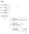
- the operation of the tablet supply unit 2, the powdered medicine supply unit 3 and the packaging unit 4 are controlled by controllers 11, 12, 13 based on the inputs from the control panel 9, the inputs from various sensors 10A to 10D, and the prescription information inputted from the outside.
- the tablet supply unit 2 is controlled by the controller 11
- the powdered medicine supply unit 3 is controlled by the controller 12
- the packaging unit 4 is controlled by the controller 13.
- two or more units among the tablet supply unit 2, the powdered medicine supply unit 3, and the packaging unit 4 may be controlled by a common controller.
- the tablet supply unit 2 includes a fixed tablet housing section 22 in which a plurality of tablet housing chambers 21 is provided in matrix form (and which constitutes part of the upper surface side of the housing 6 in the present embodiment) and a tablet discharging section 23 that automatically and sequentially takes out tablets for each dose supplied by manual distribution into the respective tablet housing chamber 21, and supplies the tablets to the packaging unit 4.
- the tablet housing section 22 in the present embodiment is provided with a total of 28 tablet housing chambers 21 in identical shape in four rows in the anteroposterior direction (row direction) and seven columns in the lateral direction (column direction). Both the upper and lower ends of the respective tablet housing chambers 21 are open.
- An upper end opening 21a functions as an opening for the operator to manually feed the tablets into the tablet housing chambers 21.
- a lower end opening 21b functions as an opening through which the tablets housed inside the tablet housing chambers 21 pass to the tablet discharging section 23.
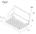
- the tablet housing section 22 includes a closing cover 25 generally in sheet shape or plate shape and a protection cover 26 also having generally sheet shape or plate shape.
- the closing cover 25 and the protection cover 26 are rotatably fixed to the upper surface of the tablet housing section 22.
- the closing cover 25 can be set to either an open position where the closing cover is receded from the tablet housing section 22 or to a closed position where the closing cover is placed on the tablet housing section 22 to close the upper end openings 21a of the seven tablet housing chambers 21 constituting the rearmost-side one row.
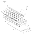
- the tablet discharging section 23 of the tablet supply unit 2 includes an upper shutter plate 34 arranged under the tablet housing section 22, a lower shutter plate 35 arranged in a state of being mutually superimposed under the upper shutter plate 34, a movable discharging member 36 arranged under the lower shutter plate 35, and a fixing plate 37 arranged under the discharging member 36.
- the upper and lower shutter plates 34, 35 are movable in the column direction of the arrangement of the tablet housing chambers 21, while holding the mutually superimposed state.
- a total of 28 tablet passage holes 41. respectively corresponding to the tablet housing chambers 21 are formed in four rows and seven columns.
- the left-side ends of the upper and lower shutter plates 34, 35 in Figs. 3A and 3B are provided with downwardly folded engaging sections 34a, 35a.
- the upper shutter plate 34 is connected to the tablet housing section 22 by a spring (not shown) so as to be elastically biased rightward in Figs. 3A and 3B .
- the lower shutter plate 35 is connected to the upper shutter plate 34 by a spring (not shown) so as to be elastically biased rightward in Figs. 3A and 3B .
- the upper and lower shutter plates 34, 35 are at positions shown in Fig. 3B .
- the discharging member 36 is reciprocatingly movable in the column direction of the arrangement of the tablet housing chambers 21 by a driving device including a pinion-rack mechanism and a motor.
- the discharging member 36 is provided with a total of 28 tablet discharging chambers 42 having the open upper and lower ends in four rows and seven columns corresponding to the tablet housing chambers 21 of the tablet housing section 22.
- Operable and closable bottom plates 43 having rotatable one ends by pins 44 and embedded weights 45 for opening are arranged at the openings on the lower end side of the respective tablet discharging chambers 42.
- the bottom plates 43 of the tablet discharging chambers 42 are placed on the upper surface of the fixing plate 37 and thereby the bottom plates 43 are held at a closed position. Further, the right-side end of the fixing plate 37 in Figs. 3A, 3B , and 5 is provided with stages 37a to 37d in identical number to the number of rows of the tablet housing chambers 21 and the tablet discharging chambers 42 (four rows in the present embodiment).
- the tablet supply unit 2 First, the tablets are fed from the upper end openings 21a by the manual distribution operation and the tablets are housed in the respective tablet housing chambers 21.
- the tablet discharging section 23 is operated to send the tablets supplied from the tablet housing section 22 to a hopper 67 of the packaging unit 4 through a carrier channel (not shown) one-by-one dose and packing processing is executed in the packaging unit 4. More specifically, before selection of the start button (during non-activation), the tablet discharging section 23 is in a state shown in Fig. 3A , and the lower end openings 21 b of the respective tablet housing chambers 21 are closed by the upper and lower shutter plates 34, 35.
- the discharging member 36 moves in a left direction (column direction) in Fig. 3A .
- One end of the discharging member 36 is hooked onto the engaging section 35a of the lower shutter plate 35, resulting in that the lower shutter plate 35 also moves in the left direction along with the discharging member 36.
- Further movement of the discharging member 36 in the left direction in the figure causes that the one end of the discharging member 36 is hooked onto the engaging section 34a of the upper shutter plate 34 through the engaging section 35a of the lower shutter plate 35, resulting in that the upper shutter plate 34 also moves in the left direction along with the discharging member 36.
- the tablet passage holes 41, 41 in the upper and lower shutter plates 34, 35 come to the open position where the holes are respectively opposed to the lower end openings 21 b of the respective tablet housing chambers 21 as shown in Fig. 3B .
- the openings on the upper end side of the tablet discharging chambers 42 of the discharging member 36 become a state of being respectively opposed to the respective lower end openings 21b.
- the tablets for each one dose which are housed in the respective tablet housing chambers 21 are housed into the tablet discharging chambers 42 of the discharging member 36 passing through the lower end openings 21 b and the tablet passage holes 41.
- the discharging member 36 moves in a right direction in the figure, resulting in that the bottom plates 43 of the tablet discharging chambers 42 sequentially reach a portion ahead of the stages 37a to 37d starting from the tablet discharging chamber on the front side in a moving direction so that support from the lower side is eliminated and the bottom plates are opened.
- the tablets inside the respective tablet discharging chambers 42 are sequentially supplied into the hopper 67.
- the powdered medicine supply unit 3 is manually supplied with the powdered medicine, automatically divides the powdered medicine for each dosage, and sequentially supplies the medicine to the packaging unit 4.
- the powdered medicine supply unit 3 includes a long chamber that is open to the upper surface of the housing 6 and has a roughly V-shaped section (V-chamber 51).
- the bottom section of the V-chamber 51 is openable and closable.
- a plurality of dividing containers (not shown) is arranged below the V-chamber 51. When the bottom sections are opened, the powdered medicine fed into the V-chamber 51 drops into the dividing containers to be divided into a predetermined amount.
- the bottom sections of the dividing containers are also openable and closable.
- the powdered medicines inside the respective dividing containers drop into the hopper 67, and are supplied to the packaging unit 4 one-by-one dose.
- a movable partitioning plate 52 for adjusting the number of powdered medicine to be divided is arranged in the V-chamber 51.
- the configuration of the powdered medicine supply unit 3 is not particularly limited so long as the powdered medicine can be supplied to the packaging unit 4 one-by-one dose.
- the powdered medicine supply unit 3 may have a distribution plate with an outer peripheral circular groove to which the powdered medicine is fed from a hopper, and a scraping-out device sequentially scrapes out the powdered medicine one-by-one dose from the outer peripheral circular groove to sequentially supply them to the packaging unit 4.
- the packaging unit 4 is described with reference to Figs. 6 to 22 .
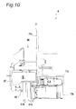
- the packaging unit 4 is provided with a sheet supply section 63, an unfolding guide 65, a hopper 67, a heat sealing section 68, and a printing section 69.
- the sheet supply section 63 rolls out and feeds a long and narrow package sheet 61 previously folded into two portions along with the longitudinal direction from a roll 62 on which the package sheet 61 is wound.
- the unfolding guide 65 unfolds and opens the two-folded package sheet 61 fed from the sheet supply section 63.
- the hopper 67 has an inlet opening 67b into which the medicine is fed from the tablet supply unit 2 and the powdered medicine supply unit 3 in its upper end, and is equipped with a nozzle section 67a which functions as a feed port for introducing the medicine into the opening of the two-folded package sheet 61 in its lower end.
- the heat sealing section 68 seals the package sheet 61 so as to enclose the introduced medicine, by which continuous medicine bags are prepared.
- the continuous medicine bags prepared by the heat sealing section 68 are cut off by a cutter mechanism (schematically shown by the reference sign 80 only in Figs. 37 and 38 ) so as to be divided into each dose.
- the divided medicine bags are discharged from the medicine discharge section 5 (see Fig. 1 ).
- the printing section 69 is placed between the sheet supply section 63 and the unfolding guide 65 along the path of the package sheet 61 to print information including a name of patient, a medicine name, and directions for use, onto the package sheet 61.
- the operation of the packaging unit 4 is controlled by the controller 13.
- the packaging unit 4 is provided in a holding frame 71 arranged in the housing space 7 of the housing 6.
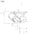
- the holding frame 71 includes a front holding section 71a extending on the front side of the housing 6, a side holding section 71b extending from the right side to a rear side seen from the front side of the front holding section 71a, and a hinge mechanism 72 rotatably connecting the side-end side on the left side seen from the front side of the front holding section 71a to the housing 6 (further refer to Figs. 11 and 12 ).
- Such a configuration achieves favorable operability as described later in detail, while allowing compact housing of the packaging unit 4 inside the housing 6.
- a base plate (not shown) is provided at a position immediately above the top of the holding frame 71 (refer to Fig. 8 ), and the tablet supply unit 2 and the powdered medicine supply unit 3 are arranged on this base plate.
- providing the packaging unit 4 on the holding frame 71 enables compact housing of the packaging unit 4 inside the housing 6 having a limited vertical space.
- the roll 62 for the package sheet 61 is arranged in a lower region of the side holding section 71b of the holding frame 71. Further, the side holding section 71b of the holding frame 71 is provided with two guide rollers 73a, 73b that constitute part of the sheet supply section 63. A rotational center of the roll 62 and the guide rollers 73a, 73b extends in the direction substantially orthogonal to the side holding section 71 b (direction in which the front holding section 71a extends). Further, the printing section 69 is arranged above the guide rollers 73a, 73b of the side holding section 71b of the holding frame 71.
- the package sheet 61 is wound off from the roll 62 to the rear side, horizontally folded by the one guide roller 73a to the front side, and further diverted upward by the other guide roller 73b to be guided to the printing section 69.
- a collar-like section may be provided at the tip of the guide rollers 73a, 73b for preventing meandering and fallout of the package sheet 61.
- the printing section 69 includes a replaceable ink cartridge 76 having a winding-off roller and a winding-up roller for a thermal transfer ink ribbon 75, a biasing roller 77 that applies tension to the ink ribbon 75, a thermal transfer head 78, and a backup roller 79 for closely contacting the package sheet 61 to the ink ribbon 75 in a portion of the thermal transfer head 78.
- curvature guide rollers 81A, 81B curve guides which curve the conveying direction of the package sheet 61 which passed the printing section 69 just before the unfolding guide 65 (see Fig. 22 for reference). More specifically, the curvature guide rollers 81A, 81B curve the conveying direction of the package sheet 61, which travels from the back side to the front side along with the side holding section 71b, toward the front side of the front holding section 71a, and guide the package sheet 61 to diagonally leftward and downward as seen from the front side of the front holding section 71a.
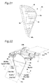
- the curvature guide rollers 81A, 81B extend from the front holding section 71a to the direction in which the front holding section 71a stretches and also to the direction slantingly downward. As most clearly shown in Figs. 6 , 9 , and 22 , the direction in which a side edge of the curvature guide roller 81B among the curvature guide rollers 81A, 81B extends on the downstream side of the conveying direction of the package sheet 61 (a chain double-dashed line C) is aligned with the direction in which a later-described main ridge 94 of the unfolding guide 65 extends.
- the unfolding guide 65 is placed on the front holding section 71a of the holding frame 71 on the left oblique downward side of the curvature guide rollers 81A, 81B as seen from the front (on the downstream side of the conveying direction of the package sheet 61).
- the unfolding guide 65 is described in detail later.
- the hopper 67 is held on the front holding section 71a of the holding frame 71, and the nozzle section 67a on the lower end of the hopper 67 is positioned on the left oblique downward side of the unfolding guide 65 as seen from the front (on the downstream side of the conveying direction of the package sheet 61).
- the heat sealing section 68 is placed in an oblique downward position from the nozzle section 67a of the hopper 67 as seen from the front (on the downstream side of the conveying direction of the package sheet 61).
- the printing section 69 is placed on the side holding section 71b of the holding frame 71 while the unfolding guide 65, the nozzle section 67a of the hopper 67, and the heat sealing section 68 are placed on the front holding section 71a of the holding frame 71, so that the printing section 69, the unfolding guide 65, the nozzle section 67a, and the heat sealing section 69 can be placed in the vicinity of each other in relatively narrow space.
- the heat sealing section 68 includes a pair of feed rollers 82a, 82b which is intermittently rotatably driven by a driving mechanism (not shown) including a motor, a direct driven gear, an intermittent gear, and the like.
- the package sheet 61 is sandwiched between the feed rollers 82a, 82b, and carried by intermittent rotation of the feed rollers 82a, 82b.
- a pair of heater rollers 83a, 83b is provided on the upstream side of the carrying direction of the package sheet 61 with respect to the feed rollers 82a, 82b.
- Each of the heater rollers 83a, 83b has a disk-shaped feed heat sealing member 84, and a thin rectangular plate-shaped longitudinal heat sealing member 86 formed on the bottom integrally with a roller member 85 having the same diameter as that of the feed heat sealing member 84.
- the feed heat sealing members 84, 84 are rotatably driven by a driving mechanism (not shown) including the common motor with the motor for the feed rollers 82a, 82b.
- the longitudinal heat sealing members 86, 86 are rotatably driven by a driving mechanism different from the mechanism for the feed heat sealing members 84, 84.
- a longitudinal seal (horizontal seal) is formed at the side edge of the package sheet 61 between the feed heat sealing members 84, 84 of both the heater rollers 83a, 83b.
- a seal across the package sheet 61 (vertical seal) is formed by the longitudinal heat sealing members 86, 86 of both the heater rollers 83a, 83b.
- the unfolding guide 65 is provided with a guide main body 91 having a function to unfold the two-folded package sheet 61 and to form an opening 101 for inserting the nozzle section 67a of the hopper 67, and a long and narrow plate-shaped attaching section 93 for fixing the guide main body 91 to the front holding section 71a of the holding frame 71 via a bracket 92 (see Figs. 6 to 8 ).
- the unfolding guide 65 is screwed to the bracket 92 with screws (not shown) inserted into through holes 93a, 93b of the attaching section 93, respectively.
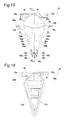
- the guide main body 91 of the unfolding guide 65 has the main ridge 94 extending along with a crease 61a of the package sheet 61, a pair of unfolding guide surfaces 95a, 95b which are convex curved surfaces stretching from the main ridge 94 seen from the conveying direction (see arrow A in Figs.
- a sub ridge 90 extending from an end section 94a of the main ridge 94 on the upstream side of the conveying direction A of the package sheet 61 to the upstream side of the conveying direction A continuously from the main ridge 94, a pair of top surfaces 96a, 96b which are convex curved surfaces stretching from the sub ridge 90 seen from the upstream side of the conveying direction A of the package sheet 61, and rear end edges 97a, 97b sequentially extending from the upstream side of the conveying direction A of the package sheet 61 to the downstream side toward the main ridge 94 and connected to an end section 94b of the main ridge 94 on the downstream side of the conveying direction A.
- the guide main body 91 is generally a smooth curved surface which becomes narrower toward the downstream side of the conveying direction A of the package sheet 61 (widened toward the upstream side of the conveying direction A of the package sheet 61).
- the guide main body 91 seen from the rear side has recessed shape or hollow shape, and this hollow section is closed by a closing plate 98 schematically shown only in Fig. 21 so as to prevent the medicine (powdered medicine in particular) from stagnating.
- the unfolding guide surfaces 95a, 95b are provided with shoulder sections 99a, 99b on the top of the conveying direction A of the package sheet 61.
- the unfolding guide surfaces 95a, 95b are smoothly connected to the top surfaces 96a, 96b at the shoulder sections 99a, 99b.
- the shoulder sections 99a, 99b of the unfolding guide surfaces 95a, 95b have thin ridge shape.
- the unfolding guide surfaces 95a, 95b will indicate portions of the unfolding guide surfaces 95a, 95b excluding the shoulder sections 99a, 99b unless otherwise specified.
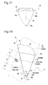
- an outline of the unfolding guide surfaces 95a, 95b is a convex curve, and a distance between the pair of unfolding guide surfaces 95a, 95b is widened as they are farther away from the main ridge 94 (see Figs. 17 , 19, and 20 ).
- the outline of the unfolding guide surfaces 95a, 95b is generally linear or straight, and the distance between the unfolding guide surfaces 95a, 95b gradually becomes narrower from the upstream side to the downstream side of the conveying direction A of the package sheet 61 (see Fig. 15 ).
- the unfolding guide 65 is provided with the pair of unfolding guide surfaces 95a, 95b which are convex curved surfaces, and the direction in which the side edge of the curvature guide roller 81B among the curvature guide rollers 81A, 81B extends on the downstream side of the conveying direction A of the package sheet 61 1 (chain double-dashed line C in Figs. 6 , 9 , and 22 ) is aligned with the direction in which the main ridge 94 of the unfolding guide 65 extends.
- the direction in which the side edge of the curvature guide roller 81B extends (chain double-dashed line C) and the direction in which the main ridge 94 extends are on an identical plane stretching in the vertical direction.
- the two-folded package sheet 61 is guided with the curved surfaces and is thereby gently deformed or unfolded, so that the tension can be equally applied to both the two portions of the two-folded package sheet 61 while the opening 101 can be formed. Therefore, even if the printing section 69, the unfolding guide 65, the nozzle section 67a of the hopper 67, and the heat sealing section 68 are placed in the vicinity of each other, it becomes possible to reliably prevent wrinkles from being generated on the package sheet 61 in the heat sealing section 68.
- the shape of the unfolding guide 65 can reduce a distance from the printing section 69 to the heat sealing section 68 without generating the wrinkles on the package sheet 61.
- a length of the useless package sheet 61 used only for routing upon the initial startup of the medicine packaging apparatus 1 or at the time of replacement of the roll 62 and not for packaging of the medicine can be reduced to the minimum, and running cost reduction can be achieved thereby.
- downsizing of the device can be attained by reducing the distance from the printing section 69 to the heat sealing section 68.
- the reference sign 100a in Fig. 15 denotes a contact start position with the package sheet 61 (a portion 61b on the left side of the crease 61a in Fig. 13 ) of the unfolding guide surface 95a located on the outer side of a curve in the conveying direction A relative to the main ridge 94 as seen from the direction orthogonal to the conveying direction A of the package sheet 61 and facing the main ridge 94 (arrow B in Figs. 13 , 18 , and 22 ).
- the reference sign 100b in Fig. 15 denotes a contact start position with the package sheet 61 (a portion 61c on the right side of the crease 61a in Fig.
- the contact start positions 100a, 100b are positioned on the shoulder sections 99a, 99b among the unfolding guide surfaces 95a, 95b.
- the contact start position 100a of the unfolding guide surface 95a on the outer side of the curve in the conveying direction A is positioned above the contact start position 100b of the unfolding guide surface 95b on the inner side of the curve in the conveying direction A. That is, the contact start position 100a on the outer side of the curve in the conveying direction A is positioned slightly on the upstream side of the conveying direction A relative to the contact start position 100b on the inner side of the curve.
- the portion 61b of the two-folded package sheet 61 on the outer side of the curve and the portion 61c on the inner side of the curve start to come into contact with the corresponding unfolding guide surfaces 95a, 95b at the same time.
- the two-folded package sheet 61 can be more smoothly unfolded so that the opening 101 can be formed, and it becomes possible to more reliably prevent the wrinkles from being generated on the package sheet 61 in the heat sealing section 68.
- the unfolding guide surfaces 95a, 95b in the present embodiment are not curved surfaces without concave and convex (geometrically continuous curved surfaces) but have fine concave and convex as described in detail later.
- an area a2 adjacent to the area a1 within a certain range further on the downstream side of the conveying direction A is slightly recessed. That is, intermediate concave sections (first concave sections) 103a, 103b are formed in the area a2.
- the intermediate concave sections 103a, 103b are formed from positions spaced from the main ridge 94 to the rear end edges 97a, 97b. In other words, the intermediate concave sections 103a, 103b are not formed at positions near the main ridge 94 even in portions included in the area a2, but the unfolding guide surfaces 95a, 95b are bulged at the same level as the area a1 (upstream portions 102a, 102b) at the positions even in the area a2.
- intermediate concave sections 103a, 103b are the relatively radical concave shape with respect to the upstream portions 102a, 102b, and stages 104a, 104b are formed between the upstream portions 102a, 102b and the intermediate concave sections 103a, 103b.
- the two-folded package sheet 61 When the medicine is introduced into the opening 101 of the two-folded package sheet 61 from the nozzle section 67a of the hopper 67 on the downstream side of the unfolding guide 65, the two-folded package sheet 61 is bulged in accordance with the volume of the medicine (a distance between the two portions 61b, 61c which sandwich the crease 61a of the two-folded package sheet 61 is stretched). Particularly when the volume of the medicine to be introduced is large, the bulge of this package sheet 61 is notable.
- the intermediate concave sections 103a, 103b in the unfolding guide surfaces 95a, 95b, even when the bulge is generated in accordance with the introduction of the medicine, it becomes possible to prevent excessive tension applied to the package sheet 61. As a result, it becomes possible to more reliably prevent the wrinkles from being generated on the package sheet 61 in the heat sealing section 68.
- the package sheet 61 can be unfolded in a state that some margins are left for the bulge of the package sheet 61 in accordance with the introduction of the medicine (a state that the bulge can be "absorbed"), so that the opening 101 can be formed.
- the package sheet 61 has the margins for the bulge due to the intermediate concave sections 103a, 103b, the package sheet 61 can ease a shock received from the medicine introduced from the nozzle section 67a of the hopper 67. By this shock easing, it becomes possible to prevent the medicine (powdered medicine in particular) from being blown up in the two-folded package sheet 61.
- the two portions 61b, 61c of the package sheet 61 cannot be sufficiently unfolded with respect to the crease 61a in portions near the contact start positions 100a, 100b, that is, the upstream portions 102a, 102b, and the opening 101 of the size required for the introduction of the medicine from the nozzle section 67a of the hopper 67 cannot be secured.
- the upstream portions 102a, 102b are not recessed but the intermediate concave sections 103a, 103b are partially formed in the unfolding guide surfaces 95a, 95b.
- end concave sections 105a, 105b made by recessing the unfolding guide surfaces 95a, 95b more than the intermediate concave sections 103a, 103b are formed in an area a3 on the downstream side of the area a2 in which the intermediate concave sections 103a, 103b are formed, the area a3 including the end section 94b of the main ridge 94 on the downstream side.
- Each of the end concave sections 105a, 105b in the present embodiment is formed by providing a triangle concave 106, a reversed-triangle concave 107, and a square concave 108 in order from the side of the main ridge 94.
- An area of the end concave section 105a of the unfolding guide surface 95a located on the outer side of the curve in the conveying direction A relative to the main ridge 94 is set to be larger than an area of the end concave section 105b of the unfolding guide surface 95b located on the inner side of the curve in the conveying direction A relative to the main ridge 94.
- the respective portions 61b, 61c of the two-folded package sheet 61 come into close contact with the end concave sections 105a, 105b of the corresponding unfolding guide surfaces 95a, 95b, and an amount of the package sheet 61 corresponding to this close contact is fed to the portion on the downstream side of the unfolding guide 65 into which the medicine is introduced. That is, by providing the end concave sections 105a, 105b in addition to the intermediate concave sections 103a, 103b, a margin amount for the bulge of the package sheet 61 in accordance with the introduction of the medicine is increased.
- an angle ⁇ 1 (acute angle) made by the above-mentioned rear end edges 97a, 97b of the unfolding guide 65 and the main ridge 94 at a joining position with the end section 94b of the main ridge 94 on the downstream side is set to be larger than an angle ⁇ 2 (acute angle) with respect to the main ridge 94 at regions other than the joining position with the end section 94b of the main ridge 94 on the downstream side.
- the angle ⁇ 1 is 70° and the angle ⁇ 2 is 35°.
- the area of the unfolding guide surfaces 95a, 95b can be set wide enough to prevent the wrinkles from being generated on the package sheet 61 but not to prevent the transportation of the package sheet 61 by frictional resistance.
- a portion of the unfolding guide 65 on the upstream side of the conveying direction A of the package sheet 61 has the sub ridge 90 extending continuously from the main ridge 94 as stated above, and the pair of top surfaces 96a, 96b which are convex curved surfaces stretching substantially symmetrically with respect to the sub ridge 90.
- the roll 62 of the package sheet 61, the guide rollers 73a, 73b, the printing section 69, the backup roller 79, the curvature guide roller 81, the unfolding guide 65, the hopper 67, and the heat sealing section 68 can be placed compactly, and the space in the housing space 7 of the housing 6 can be utilized. In other words, downsizing of the medicine packaging apparatus 1 can be achieved. If the holding frame 71 is rotated by the hinge mechanism 72 as shown in Fig.
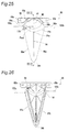
- a second embodiment of the present invention shown in Figs. 23 to 29 is different from the first embodiment only in the configuration of the unfolding guide 65.
- the shoulder sections 99a, 99b of the unfolding guide surfaces 95a, 95b are wide and an area of the top surfaces 96a, 96b is correspondingly narrow.
- the unfolding guide surfaces 95a, 95b excluding the shoulder sections 99a, 99b are smooth curved surfaces without concave as a whole, and have long and narrow flat sections 109a, 109b extending along the rear end edges 97a, 97b.
- the outline of the unfolding guide surfaces 95a, 95b excluding the flat sections 109a, 109b is a convex curve, and the distance between the pair of unfolding guide surfaces 95a, 95b is widened as they are farther away from the main ridge 94.
- the outline of the unfolding guide surfaces 95a, 95b is generally linear or straight, and the distance between the unfolding guide surfaces 95a, 95b becomes narrower from the upstream side to the downstream side of the conveying direction A of the package sheet 61.
- the unfolding guide 65 is provided with the pair of unfolding guide surfaces 95a, 95b which are convex curved surfaces. As most clearly shown in Figs. 6 , 9 , and 22 , the direction in which the side edge of the curvature guide roller 81B among the curvature guide rollers 81A, 81B extends on the downstream side of the conveying direction A of the package sheet 61 (chain double-dashed line C) is aligned with the direction in which the main ridge 94 of the unfolding guide 65 extends.
- the two-folded package sheet 61 is guided with the curved surfaces and thereby gently deformed or unfolded while equally applying the tension to the two-folded package sheet 6 1 so that the opening 101 can be formed.
- the printing section 69, the unfolding guide 65, the nozzle section 67a of the hopper 67, and the heat sealing section 68 are placed in the vicinity of each other (even if the distance from the printing section 69 and the heat sealing section 68 is reduced), it becomes possible to reliably prevent the wrinkles from being generated on the package sheet 61 in the heat sealing section 68.
- the contact start positions 100a, 100b with the package sheet 61 of the unfolding guide surfaces 95a, 95b are included in the shoulder sections 99a, 99b.
- the contact start position 100a of the unfolding guide surface 95a on the outer side of the curve in the conveying direction A is positioned above the contact start position 100b of the unfolding guide surface 95b on the inner side of the curve in the conveying direction A. That is, the contact start position 100a on the outer side of the curve is positioned slightly on the upstream side of the conveying direction A relative to the contact start position 100b on the inner side of the curve.
- the portions 61b, 61c of the two-folded package sheet 61 on the outer side and the inner side of the curve start to come into contact with the corresponding unfolding guide surfaces 95a, 95b at the same time.
- the two-folded package sheet 61 can be more smoothly unfolded so that the opening 101 can be formed, and it becomes possible to more reliably prevent the wrinkles from being generated on the package sheet 61 in the heat sealing section 68.
- a bulge amount Pin of the unfolding guide surface 95b located on the inner side of the curve in the conveying direction A of the package sheet 61, the bulge amount relative to the main ridge 94 at the contact start position 100b of the shoulder section 99b is set to be larger than a bulge amount Pout of the unfolding guide surface 95a located on the outer side of the curve in the conveying direction relative to the main ridge 94, the bulge amount relative to the main ridge 94 at the contact start position 100a of the shoulder section 99a.
- the unfolding guide surfaces 95a, 95b are asymmetrical relative to the main ridge 94, and the unfolding guide surface 95b located on the inner side of the curve in the conveying direction A of the package sheet 61 is in the shape bulging more than the unfolding guide surface 95a located on the outer side of the curve.
- the tension applied to the portion 61c of the two-folded package sheet 61 on the inner side of the curve in the conveying direction A tends to be weaker than the tension applied to the portion 61b on the outer side of the curve. Imbalance of the tension between the inner side and the outer side tends to make the portion 61c of the two-folded package sheet 61 on the inner side of the curve slack, and this slacking causes a misaligned state (so-called "edge displacement") of both the edges (so-called "edges”) of the two portions 61b, 61c of the two-folded package sheet 61.
- the contact resistance of such members as the heat transfer head 78 of the printing section 69 positioned on the upstream side of the unfolding guide 65 and the curvature guide rollers 81A, 81B also tends to promote the imbalance of the tension between the portion 61c of the package sheet 61 on the inner side and the portion 61b on the outer side.
- the unfolding guide surface 95b located on the inner side of the curve in the conveying direction A of the package sheet 61 is in the shape bulging more than the unfolding guide surface 95a located on the outer side of the curve, so that the tension applied to the package sheet 61 from the main ridge 94, both the shoulder sections 99a, 99b, and both the unfolding guide surfaces 95a, 95b is balanced.
- the tension uniformly acts on both the portions 61b, 61c of the two-folded package sheet 61, and therefore the package sheet 61 can be unfolded by the unfolding guide 65 with both the edges aligned (in the state of so-called "edge aligned” state), so that generation of the wrinkles can be prevented more reliably.
- a linear projection 110 extending in the direction crossing the main ridge 94 is formed at a position adjacent to the contact start position 100a with the package sheet 61 of the unfolding guide surface 95a located on the outer side of the curve in the conveying direction A relative to the main ridge 94.
- the linear projection 110 has one end (an end section on the left side in Fig. 28 ) positioned in a border between the flat section 109a of the unfolding guide surface 95a and the portion of the curved surface, and the other end (an end section on the right side in Fig. 28 ) positioned in an intermediate area between the main ridge 94 and the rear end edge 97b.
- the bulge amount of the unfolding guide surface 95a on the outer side of the curve in the conveying direction A relative to the main ridge 94 in the portion of the linear projection 110 is also smaller than the bulge amount Pin of the unfolding guide surface 95b on the inner side of the curve relative to the main ridge 94 at the contact start position 100b.
- the frictional resistance between the package sheet 61 and the unfolding guide surfaces 95a, 95b tends to be larger on the outer side of the curve than on the inner side of the curve.
- the package sheet 61 Since the frictional resistance between the package sheet 61 and the unfolding guide surface 95a is reduced by this reduction of the contact area, the package sheet 61 can be unfolded while being more smoothly fed to the heat sealing section 68. Thereby, it becomes possible to more reliably prevent the wrinkles from being generated in the heat sealing section 68.
- the portion 61b of the package sheet 61 is slightly floating from the unfolding guide surface 95a in a region between the linear projection 110 and the portion near the main ridge 94.
- the portion 61b of the package sheet 61 in this region comes into close contact with the unfolding guide surface 95a, and an amount of the package sheet 61 corresponding to this close contact is fed to the portion on the downstream side of the unfolding guide 65 into which the medicine is introduced. That is, by providing the linear projection 110, the margin amount for the bulge of the package sheet 61 in accordance with the introduction of the medicine is increased.
- the volume of the medicine to be introduced is large, it becomes possible to more reliably prevent excessive tension applied to the package sheet 61, and hence it becomes possible to more reliably prevent the wrinkles from being generated in the heat sealing section 68.
- the unfolding guide 65 in the first embodiment can also employ the configuration in which the unfolding guide surfaces 65a, 65b are asymmetrical as in the present embodiment, that is, the configuration in which the bulge amount of the unfolding guide surface 95b on the inner side of the curve in the conveying direction A relative to the main ridge 94 at the contact start position 100b is set to be larger than the bulge amount of the unfolding guide surface 95a on the outer side of the curve relative to the main ridge 94 at the contact start position 100a.
- a third embodiment of the present invention is described with reference to Figs. 30 to 38 .
- the third embodiment is different from the first embodiment only in the packaging unit 4 of the medicine packaging apparatus 1.
- a fixed guide rod 181 is placed (see Fig. 12 in particular). More specifically, the guide rod 181 curves the conveying direction of the package sheet 61, which travels from the back side to the front side along with the side holding section 71b, toward the front side of the front holding section 71a, and guides the package sheet 61 to diagonally downward as seen from the front side of the front holding section 71a.
- the guide rod 181 extends from the front holding section 71 a to the direction in which the front holding section 71 a stretches and also to the direction slantingly downward.
- the direction in which a side edge of the guide rod 181 extends on the downstream side of the conveying direction of the package sheet 61 is aligned with the direction in which the main ridge 94 of the unfolding guide 65 extends (two directions are on an identical plane).
- the third embodiment is similar to the first embodiment in the configuration and operation of the tablet supply unit 2, the powdered medicine supply unit 3, and the medicine discharge section 5.
- the packaging unit 4 in the present embodiment has a mechanism for preventing the tablets fed from the tablet supply unit 2 to the hopper 67 as well as the powdered medicine fed from the powdered medicine supply unit 3 to the hopper 67 from adhering to a wall surface in the hopper 67 and remaining in the hopper 67 without being fed to the package sheet 61. More specifically, the packaging unit 4 in the present embodiment is provided with a hopper-side vibration applying mechanism 202 for applying vibration to the hopper 67 and an unfolding guide-side vibration applying mechanism 203 for applying the vibration to the unfolding guide 65.
- the hopper 67 in the present embodiment has an inlet opening 67b in generally a rectangular shape in plan view, and has four inner inclined wall surfaces 67c, 67d, 67e, and 67f extending slantingly downward from the inlet opening 67b toward the nozzle section 67a.
- the space surrounded with the inner inclined wall surfaces 67c to 67f is divided by a partitioning plate section 67g.
- the tablets are fed from the tablet supply unit 2 to the space on the left-hand side of the partitioning plate section 67g, while the powdered medicine is fed from the powdered medicine supply unit 3 to the space on the right-hand side.
- the inner inclined wall surface 67c on the right-hand side of the partitioning plate section 67g in Fig. 33 among the four inner inclined wall surfaces 67c to 67f is set to have an angle of gradient smaller than that of the three remaining inner inclined wall surfaces 67d to 67f. More specifically, the inner inclined wall surfaces 67d to 67f have an angle of gradient set at about 75 to 85°, whereas the inner inclined wall surface 67c has an angle of gradient set at about 35 to 40°.
- the inwardly inclined surface 67e has an angle of gradient set at 64°.
- the hopper 67 in the present embodiment has a held section 67h held by a later-described hopper holding section 206 of the hopper-side vibration applying mechanism 202.
- the held section 67h is provided near the inlet opening 67b outside the inner inclined wall surface 67f.
- the held section 67h which is in the shape of a long and narrow block having a recess section 67i formed on its lower-end side, has an inclined held surface 67j formed in one end side (left-hand side in Fig. 33 ) and a projection 67k formed in the other end side.
- a knob 67m for the operator to grasp the hopper 67 is provided near the inlet opening 67b outside the inner inclined wall surface 67d facing the held section 67h.
- the hopper-side vibration applying mechanism 202 has a holding structure 205 made of resin fixed to the holding frame 71 via a bracket 204.
- the holding structure 205 has the long and narrow hopper holding section 206 extending in the horizontal direction.
- the hopper 67 is held by the hopper holding section 206 in the posture that the longitudinal direction of the inlet opening 67b (direction in which upper edges of the inwardly inclined surfaces 67d, 67f extend) is identical to the longitudinal direction of the hopper holding section 206 in plan view.
- the hopper holding section 206 has a reversed L-shaped hooking section 206a which projects upward in a section rather close to the center than the right end in Fig. 33 , and has a locking mechanism 206b on the upper side near the left end.
- the locking mechanism 206b has a manipulation lever 206c rotatable around a horizontal shaft line (see arrow D).
- the locking mechanism 206b is placed closer to the center of the hopper holding section 206a than the manipulation lever 206c, and similarly has a locking lever 206d rotatable around the horizontal shaft line (see arrow E).
- the held section 67h of the hopper 67 is removably fixed onto the hopper holding section 206.
- the projection 67k of the held section 67h fits into the lower side of the hooking section 206a of the hopper holding section 206, and the held surface 67j is pressed by a holding surface 206g of the locking lever 206d.
- the locking lever 206d is held in an unrotatable state by a fixed section 206e on the opposite side of the holding surface 206g being engaged with a fixing section 206f of the manipulation lever 206c.
- the fixing section 206f of the manipulation lever 206c is released from the fixed section 206e of the locking lever 206d.
- the locking lever 206d becomes rotatable and the held surface 67j is released from pressing by the holding surface 206g, by which the held section 67h of the hopper 67 becomes removable from the hopper holding section 206.
- the configuration for removably mounting the hopper 67 onto the hopper holding section 206 is not limited to the configuration of the present embodiment as long as the hopper 67 can firmly be fixed to the hopper holding section 206 to some degree.
- the hopper 67 may be removably mounted on the hopper holding section 206 by fixation with magnets, screw clamps and the like.
- a vibration motor holding section 207 is provided below a right end section of the hopper holding section 206 in Fig. 33 .
- the vibration motor holding section 207 is provided with a cylindrical main body 207a for holding a vibration motor 208 inside and a coupling section 207b for coupling the main body 207a to the undersurface of the hopper holding section 206.
- the vibration motor 208 is held in a manner to be hung from the undersurface side of one end of the hopper holding section 206.
- the vibration motor 208 used in the present embodiment is a type of the motor having a weight fixed to the rotation shaft of a direct-current motor incorporated in a casing.
- a later-described vibration motor 211 is also of the same type as the vibration motor 208.
- the upper end side of the holding structure 205 is coupled to the hopper holding section 206, while the lower end side has two leaf spring sections 209a, 209b fixed to the bracket with screws.
- the leaf springs 209a, 209b extend right under the hopper holding section 206 (vertically downward).
- the leaf spring sections 209a, 209b extend slantingly downward from the hopper holding section 206 in parallel with each other so as to be farther away from the vibration motor holding section 207 (vibration motor 208) toward the lower end side, and are placed in the longitudinal direction of the hopper holding section 206 at an interval.
- An angle of gradient ⁇ of the leaf spring sections 209a, 209b with respect to the horizontal direction is set at, for example, around 80°.
- the leaf spring sections 209a, 209b sag like a cantilever with the lower end side being a fixed end while the upper end side being a free end, and upon displacement of the upper ends of the leaf spring sections 209a, 209b due to the sagging, the hopper holding section 206 is also displaced thereby.
- Vibration generated by operation of the vibration motor 208 is transmitted to the hopper 67 via the holding structure 205.
- the tablets fed from the tablet supply unit 2 and the powdered medicine fed from the powdered medicine supply unit 3 promptly move from the inlet opening 67b to the nozzle section 67a without adhering to the inner inclined wall surfaces 67c to 67f of the hopper 67, and are introduced into the opening of the two-folded package sheet 61 unfolded by the unfolding guide 65. Therefore, contamination can be eliminated by effectively preventing the medicine (powdered medicine in particular) from adhering to and remaining in the hopper 67.
- a sound made by application of the vibration is small in volume and causes neither displeasure of the operator nor false detection of failure by the operator.
- the above-constituted holding structure 205 in the present embodiment transmits the vibration generated by the vibration motor 208 to the hopper 67 so that the hopper 67 may vibrate with an elliptical orbit which is farther away from the inwardly inclined surface 67c toward the upper end side.
- a major axis M of the elliptical orbit H of the vibration of the hopper 67 is perpendicular to the leaf spring sections 209a, 209b (angle of gradient ⁇ ), and an angle ⁇ H formed between the major axis M and the moving direction F of the powdered medicine which moves on the inwardly inclined surface 67c by its own weight is less than 90 degrees but is relatively large (about 45 degrees or more and less than 90 degrees).
- Application of the vibration with such elliptical orbit makes it possible to efficiently move the powdered medicine on the inwardly inclined surface 67c having mild inclination from the inlet opening 67b to the nozzle section 67a, and to reliably prevent the residual medicine generated by adhesion.
- the vibration motor 208 Since the vibration motor 208 is positioned in the vicinity of the upper end of the inwardly inclined surface 67c, the vibration generated by the vibration motor 208 is efficiently transmitted to the inwardly inclined surface 67c and promotes movement of the medicine on the inwardly inclined surface 67c.
- the unfolding guide-side vibration applying mechanism 203 is equipped with the vibration motor (second vibration source) 211 built in the unfolding guide 65.
- a plurality of radially extending ribs 212 is provided in the unfolding guide 65, and the vibration motor 211 is fixed to the unfolding guide 65 with these ribs 212. Therefore, the vibration generated by the vibration motor 211 is directly transmitted to the unfolding guide 65.
- the hopper-side vibration applying mechanism 202 and the unfolding guide-side vibration applying mechanism 203 operate in synchronization, so that the hopper-side vibration applying mechanism 202 and the unfolding guide-side vibration applying mechanism 203 operate and stop simultaneously on a constant basis.
- the hopper-side vibration applying mechanism 202 and the unfolding guide-side vibration applying mechanism 203 may operate independently of each other.
- the hopper-side vibration applying mechanism 202 and the unfolding guide-side vibration applying mechanism 203 are referred to as vibration applying mechanisms 202, 203 in the following description.
- the vibration applying mechanisms 202, 203 start operation after the elapse of a predetermined time.
- the operation duration of the vibration applying mechanisms 202, 203 is set in response to packing speed.
- the feed rate of the package sheet 61 with the feed rollers 82a, 82b (see, e.g., Figs.
- operation timing and operation duration of the vibration applying mechanisms 202, 203 are set in conformity to the case of the powdered medicine packing.
- the controller 11 When one prescription includes both a medicine bag of the tablets and a medicine bag of the powdered medicine (mixed packing), the controller 11 operates the vibration applying mechanisms 202, 203 for the medicine bag of the powdered medicine with use of the timing and operation duration similar to the powdered medicine packing, and operates the vibration applying mechanisms 202, 203 for the medicine bag of the tablets with use of the timing and operation duration similar to the tablet packing.
- the controller 11 does not operate the vibration applying mechanisms 202, 203 but keeps them in a stopped state during preparation of the medicine bag of the tablets once the medicine bag of the powdered medicine is completed during mixed packing.
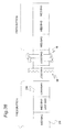
- FIG. 36 schematically shows the operation of the vibration applying mechanisms 202, 203 during mixed packing.
- 3 doses of the medicine are prepared in which the tablets are taken in the "morning" and the "non", and the powdered medicine is taken in the "evening.”
- a symbol “o” shown below a schematically depicted medicine bag 215 indicates that the vibration applying mechanisms 202, 203 are operated, whereas a symbol “x” indicates that the vibration applying mechanisms 202, 203 are maintained in the stopped state.
- the first and second medicine bags 215 contain the tablets, and the powdered medicine is not yet packaged in the same prescription. Even though the first and second medicine bags 215 contain the tablets, the vibration applying mechanisms 202, 203 are operated as in the case of the powdered medicine.
- the third medicine bag 215 is the first medicine bag which packs the powdered medicine within the same prescription, and the vibration applying mechanisms 202, 203 are also operated during preparation of the third medicine bag 215.
- the vibration applying mechanisms 202, 203 are maintained in the stopped state, whereas during preparation of the sixth and ninth medicine bags 215 in which the powdered medicine is packed, the vibration applying mechanisms 202, 203 are operated.
- empty medicine bags (loss bags 216) containing no medicine are provided in order to separate continuous medicine bags by prescription, and the loss bags 216 are cut off by the cutter mechanism 80. If the medicine (powdered medicine in particular) is mixed in the loss bags 216, the mixed medicine flows out into the device upon cutting by the cutter mechanism 80, and thereby causes the contamination. Therefore, once the controller 11 determines that the loss bags 216 are in preparation based on the inputted prescription information, the vibration applying mechanisms 202, 203 are maintained in the stopped state. Since the first loss bag 216 in the example of Fig. 37 , and the second loss bag 216 in the example of Fig. 38 are subjected to cutting by the cutter mechanism 80, the vibration applying mechanisms 202, 203 are maintained in the stopped state during preparation of these loss bags 216.
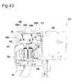
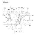
- a fourth embodiment of the present invention is described with reference to Figs. 39 to 44 .
- the fourth embodiment is different from the third embodiment in the configuration of the held section 67h of the hopper 67 and the hopper-side vibration applying mechanism 202.
- the held section 67h of the hopper 67 in the present embodiment has block-shaped first and second portions 67n, 67p provided near the inlet opening 67b outside the inner inclined wall surface 67f.
- An inclined held surface 67q is formed in one end side (left-hand side in Fig. 44 ) of the first section 67n, while a projection 67r is formed in the other end side.
- a projection 67s is also provided in one end side (right-hand side in Fig. 44 ) of the second portion 67p.
- the holding structure 205 included in the hopper-side vibration applying mechanism 202 of the present embodiment has a base 307 independent of the hopper holding section 206.
- the hopper holding section 206 and the base 307 are coupled to each other with independent leaf springs 308a, 308b having both upper and lower ends screwed shut.
- the leaf springs 308a, 308b extend right under the hopper holding section 206 (vertically downward).
- the leaf springs 308a, 308b extend slantingly downward from the hopper holding section 206 in parallel with each other so as to be closer to the vibration motor holding section 207 (vibration motor 208) toward the lower end side, and are placed in the longitudinal direction of the hopper holding section 206 at an interval.
- An angle of gradient ⁇ of the leaf springs 308a, 308b with respect to the horizontal direction is set at, for example, around 80°.
- the leaf springs 308a, 308b sag like a cantilever with the lower end side being a fixed end while the upper end side being a free end, and upon displacement of the upper ends of the leaf springs 308a, 308b due to the sagging, the hopper holding section 206 is also displaced thereby.
- the above-constituted holding structure 205 in the present embodiment transmits the vibration generated by the vibration motor 208 to the hopper 67 so that the hopper 67 may vibrate with an elliptical orbit which is farther away from the inwardly inclined surface 67c toward the upper end side.
- the major axis M of the elliptical orbit H of the vibration of the hopper 67 is perpendicular to the leaf springs 308a, 308b (angle of gradient ⁇ ), and the angle ⁇ H formed between the major axis H and the moving direction F of the powdered medicine which moves on the inwardly inclined surface 67c by its own weight is an acute angle sufficiently smaller than 45 degrees (about 5° to 15°).
- Application of the vibration with such elliptical orbit makes it possible to efficiently move the powdered medicine on the inwardly inclined surface 67c having mild inclination from the inlet opening 67b to the nozzle section 67a, and to reliably prevent the residual medicine generated by adhesion.
- the angle ⁇ H is a relatively obtuse angle as in the third embodiment
- setting the angle ⁇ H to be a sufficiently small acute angle makes it possible to enhance the movement speed of the powdered medicine on the inwardly inclined surface 67c. Since the vibration motor 208 is positioned in the vicinity of the upper end of the inwardly inclined surface 67c, the vibration generated by the vibration motor 208 is efficiently transmitted to the inwardly inclined surface 67c and promotes the movement of the medicine on the inwardly inclined surface 67c.
- the hopper holding section 206 in the present embodiment has reverse L-shaped hooking sections 306a, 306b protruding upward.
- the hopper holding section 206 is equipped with a rotatable lever 306d which functions as a locking mechanism 306c.
- a rotatable lever 306d which functions as a locking mechanism 306c.
- FIG. 44 when the hopper 67 is fixed to the hopper holding section 306, projections 67r, 67s of the held sectionh 67 fit into the lower side of the hooking sections 306a, 306b, and the held surface 67q is pressed by a holding surface 306e of the lever 306d.
- the lever 306d is rotated clockwise in Fig. 44 , the holding surface 306e of the lever 306d is released from the held surface 67q, and the hopper 67 becomes removable from the hopper holding section 206.
- the feeding configuration of the package sheet 61 is not particularly limited. More specifically, the package sheet 61 may be held in the state of being wound around the roll 62 without being folded into two portions, and may be folded into two portions after being rolled out from the roll 62. Although not shown in Figs. 39 to 44 , the unfolding guide-side vibration applying mechanism is housed in the unfolding guide 65 as in the third embodiment.
- three guide rollers 401a, 401 b, 401c are provided instead of the two curvature guide rollers 81A, 81B (first and second embodiments) and the guide rod 181 (third and fourth embodiments).
- the conveying direction of the package sheet 61 is curved just before the unfolding guide 65 with these guide rollers 401a to 401c.
- a projection 410 in small-diameter cylinder shape protruding upward is provided on the upper top section of the guide roller 401a which is closest to the unfolding guide 65 among the three guide rollers 401a to 401c.
- the projection 410 has a function to prevent meandering and fallout of the package sheet 61.
- the projection 410 can effectively prevent the meandering and the fallout of the package sheet 61. Since the peripheral surface of the small-diameter cylinder shape of the projection 410 comes into contact with the package sheet 61, the contact resistance to the package sheet 61 is very small.
Landscapes
- Engineering & Computer Science (AREA)
- Mechanical Engineering (AREA)
- Quality & Reliability (AREA)
- Basic Packing Technique (AREA)
- Containers And Plastic Fillers For Packaging (AREA)
Applications Claiming Priority (2)
| Application Number | Priority Date | Filing Date | Title |
|---|---|---|---|
| JP2008257585A JP4469007B2 (ja) | 2008-10-02 | 2008-10-02 | 薬剤包装装置 |
| PCT/JP2009/004719 WO2010038377A1 (fr) | 2008-10-02 | 2009-09-18 | Dispositif d’emballage de médicaments |
Publications (3)
| Publication Number | Publication Date |
|---|---|
| EP2336032A1 true EP2336032A1 (fr) | 2011-06-22 |
| EP2336032A4 EP2336032A4 (fr) | 2012-04-25 |
| EP2336032B1 EP2336032B1 (fr) | 2014-08-06 |
Family
ID=42073161
Family Applications (1)
| Application Number | Title | Priority Date | Filing Date |
|---|---|---|---|
| EP09817420.4A Active EP2336032B1 (fr) | 2008-10-02 | 2009-09-18 | Dispositif d emballage de médicaments |
Country Status (7)
| Country | Link |
|---|---|
| US (1) | US9056692B2 (fr) |
| EP (1) | EP2336032B1 (fr) |
| JP (1) | JP4469007B2 (fr) |
| KR (1) | KR101110509B1 (fr) |
| CN (1) | CN102143891B (fr) |
| TW (1) | TW201021786A (fr) |
| WO (1) | WO2010038377A1 (fr) |
Cited By (3)
| Publication number | Priority date | Publication date | Assignee | Title |
|---|---|---|---|---|
| US9150119B2 (en) | 2013-03-15 | 2015-10-06 | Aesynt Incorporated | Apparatuses, systems, and methods for anticipating and delivering medications from a central pharmacy to a patient using a track based transport system |
| EP2853496A4 (fr) * | 2012-05-23 | 2016-01-13 | Takazono Corp | Dispositif de séparation et d'emballage de médicament |
| US9511945B2 (en) | 2012-10-12 | 2016-12-06 | Aesynt Incorporated | Apparatuses, systems, and methods for transporting medications from a central pharmacy to a patient in a healthcare facility |
Families Citing this family (14)
| Publication number | Priority date | Publication date | Assignee | Title |
|---|---|---|---|---|
| JP5857285B2 (ja) * | 2011-12-01 | 2016-02-10 | 株式会社タカゾノテクノロジー | 薬剤供給装置 |
| WO2013105198A1 (fr) * | 2012-01-11 | 2013-07-18 | パナソニックヘルスケア株式会社 | Dispositif d'administration de médicament et procédé d'inspection de médicament dans un dispositif d'administration de médicament |
| TWI576286B (zh) * | 2014-01-09 | 2017-04-01 | Jung Hua Shao | Injection of the packaging mechanism |
| US20160009436A1 (en) * | 2014-07-14 | 2016-01-14 | Victor Basso | Machine for packing medical products and printing medical instructions for a nurse in a hospital environment |
| DK3045397T3 (en) * | 2015-01-16 | 2017-03-20 | Becton Dickinson Rowa Germany Gmbh | Packaging device for pharmaceuticals |
| US10059474B2 (en) * | 2015-01-16 | 2018-08-28 | Carefusion Germany 326 Gmbh | Packaging device for medications |
| KR102602951B1 (ko) * | 2015-06-29 | 2023-11-16 | 가부시키가이샤 유야마 세이사쿠쇼 | 약제 불출 장치 |
| JP5998346B2 (ja) * | 2015-08-24 | 2016-09-28 | 株式会社タカゾノテクノロジー | 薬剤供給装置 |
| JP6236514B2 (ja) * | 2016-11-22 | 2017-11-22 | 株式会社タカゾノ | 薬剤分包装置 |
| US10822128B2 (en) * | 2017-05-31 | 2020-11-03 | Nike, Inc. | Systems and processes for packing articles of footwear |
| KR102257372B1 (ko) * | 2019-03-13 | 2021-05-31 | (주)제이브이엠 | 약제 자동 포장기용 최종 호퍼 조립체 및 이를 가지는 약제 자동 포장기 |
| CN113697202B (zh) * | 2021-09-17 | 2022-06-21 | 无锡锡州机械有限公司 | 一种避免漏测的装箱系统及设备 |
| EP4393831A4 (fr) * | 2021-09-29 | 2025-05-14 | PHC Holdings Corporation | Dispositif d'alimentation en agent chimique |
| EP4529983A1 (fr) * | 2023-09-29 | 2025-04-02 | Roche Diagnostics International AG | Dispositif et procédé de fermeture d'un récipient d'échantillon |
Family Cites Families (16)
| Publication number | Priority date | Publication date | Assignee | Title |
|---|---|---|---|---|
| US2885848A (en) * | 1954-02-25 | 1959-05-12 | Kimberly Clark Co | Folding conveyor |
| DE1024868B (de) * | 1955-09-24 | 1958-02-20 | Paul Gerhard Klar | Abfuell- und Verpackungsmaschine zur Herstellung von Packungen aus schmiegsamem Verpackungsmaterial fuer Tee u. dgl. |
| NL281183A (fr) * | 1962-07-19 | |||
| US3748822A (en) * | 1970-08-21 | 1973-07-31 | Kraftco Corp | Apparatus for packaging individual slices of cheese |
| FR2483880B1 (fr) * | 1980-06-09 | 1985-10-18 | Vittel Eaux Min | Unite de conditionnement sous la forme de recipients ou de chapelet de recipients en matiere synthetique souple |
| GB9201096D0 (en) * | 1992-01-20 | 1992-03-11 | Unilever Plc | Tube-forming apparatus |
| FR2748989B1 (fr) * | 1996-05-22 | 1998-08-21 | Henaux Claude | Procede et dispositif d'ensachage multipoches et sachets ainsi obtenus |
| JP2002019737A (ja) | 2000-07-04 | 2002-01-23 | Takazono Sangyo Kk | ヒートシール装置 |
| JP4343565B2 (ja) * | 2002-10-18 | 2009-10-14 | 株式会社湯山製作所 | 包装装置 |
| CN100503370C (zh) | 2002-10-18 | 2009-06-24 | 株式会社汤山制作所 | 包装装置 |
| JP4435487B2 (ja) | 2003-02-05 | 2010-03-17 | 高園産業株式会社 | ヒートシールユニット及び薬剤分包装置 |
| JP4298343B2 (ja) | 2003-03-24 | 2009-07-15 | 株式会社湯山製作所 | 薬剤包装装置 |
| JP4371686B2 (ja) * | 2003-03-25 | 2009-11-25 | 高園産業株式会社 | 薬剤包装装置及び薬剤分包装置 |
| JP5012806B2 (ja) * | 2006-09-20 | 2012-08-29 | 株式会社湯山製作所 | 薬剤包装装置 |
| JP4220568B2 (ja) * | 2007-04-02 | 2009-02-04 | 株式会社湯山製作所 | 薬剤包装装置 |
| USD605210S1 (en) * | 2007-11-09 | 2009-12-01 | Yuyama Mfg. Co., Ltd. | Component for opening package sheets for drug packaging machines |
-
2008
- 2008-10-02 JP JP2008257585A patent/JP4469007B2/ja active Active
-
2009
- 2009-09-18 EP EP09817420.4A patent/EP2336032B1/fr active Active
- 2009-09-18 KR KR1020117007449A patent/KR101110509B1/ko active Active
- 2009-09-18 US US13/121,856 patent/US9056692B2/en active Active
- 2009-09-18 WO PCT/JP2009/004719 patent/WO2010038377A1/fr not_active Ceased
- 2009-09-18 CN CN2009801344973A patent/CN102143891B/zh active Active
- 2009-09-22 TW TW098131877A patent/TW201021786A/zh unknown
Cited By (9)
| Publication number | Priority date | Publication date | Assignee | Title |
|---|---|---|---|---|
| EP2853496A4 (fr) * | 2012-05-23 | 2016-01-13 | Takazono Corp | Dispositif de séparation et d'emballage de médicament |
| AU2013263883B2 (en) * | 2012-05-23 | 2017-05-25 | Takazono Corporation | Medicine dispensing and packing apparatus |
| US9511945B2 (en) | 2012-10-12 | 2016-12-06 | Aesynt Incorporated | Apparatuses, systems, and methods for transporting medications from a central pharmacy to a patient in a healthcare facility |
| US10029856B2 (en) | 2012-10-12 | 2018-07-24 | Aesynt Incorporated | Apparatuses, systems, and methods for transporting medications from a central pharmacy to a patient in a healthcare facility |
| US10315851B2 (en) | 2012-10-12 | 2019-06-11 | Aesynt Incorporated | Apparatuses, systems, and methods for transporting medications from a central pharmacy to a patient in a healthcare facility |
| US10518981B2 (en) | 2012-10-12 | 2019-12-31 | Aesynt Incorporated | Apparatuses, systems, and methods for transporting medications from a central pharmacy to a patient in a healthcare facility |
| US10850926B2 (en) | 2012-10-12 | 2020-12-01 | Omnicell, Inc. | Apparatuses, systems, and methods for transporting medications from a central pharmacy to a patient in a healthcare facility |
| US11694782B2 (en) | 2012-10-12 | 2023-07-04 | Omnicell, Inc. | Apparatuses, systems, and methods for transporting medications from a central pharmacy to a patient in a healthcare facility |
| US9150119B2 (en) | 2013-03-15 | 2015-10-06 | Aesynt Incorporated | Apparatuses, systems, and methods for anticipating and delivering medications from a central pharmacy to a patient using a track based transport system |
Also Published As
| Publication number | Publication date |
|---|---|
| KR101110509B1 (ko) | 2012-01-31 |
| WO2010038377A1 (fr) | 2010-04-08 |
| TWI330078B (fr) | 2010-09-11 |
| EP2336032A4 (fr) | 2012-04-25 |
| CN102143891B (zh) | 2013-11-06 |
| JP4469007B2 (ja) | 2010-05-26 |
| KR20110053258A (ko) | 2011-05-19 |
| US9056692B2 (en) | 2015-06-16 |
| TW201021786A (en) | 2010-06-16 |
| US20110197547A1 (en) | 2011-08-18 |
| JP2010083573A (ja) | 2010-04-15 |
| CN102143891A (zh) | 2011-08-03 |
| EP2336032B1 (fr) | 2014-08-06 |
Similar Documents
| Publication | Publication Date | Title |
|---|---|---|
| EP2336032B1 (fr) | Dispositif d emballage de médicaments | |
| EP2130770B1 (fr) | Appareil à emballer les médicaments | |
| JP5527461B2 (ja) | 薬剤包装装置 | |
| CN101541294B (zh) | 药剂包装装置 | |
| TWI430921B (zh) | Pharmaceutical packaging device | |
| WO2024090097A1 (fr) | Dispositif d'alimentation en médicament | |
| CN104334454A (zh) | 药剂分包装置 | |
| JP4564402B2 (ja) | ロータリー式自動包装機の原料計量供給機構における二段ホッパー | |
| JP2008272461A (ja) | 薬剤包装装置 | |
| CN100554089C (zh) | 药剂供给装置 | |
| KR102795403B1 (ko) | 착탈형 패키징 유니트를 구비한 정제약 포장장치 | |
| JPH0811576B2 (ja) | 包装機のシール装置 | |
| KR102855142B1 (ko) | 정제약 포장기용 포장지 연속 폴딩장치 | |
| KR101460506B1 (ko) | 약제포장장치의 포장모듈 | |
| JPH05132006A (ja) | 自動錠剤包装機の錠剤投入装置 |
Legal Events
| Date | Code | Title | Description |
|---|---|---|---|
| PUAI | Public reference made under article 153(3) epc to a published international application that has entered the european phase |
Free format text: ORIGINAL CODE: 0009012 |
|
| 17P | Request for examination filed |
Effective date: 20110331 |
|
| AK | Designated contracting states |
Kind code of ref document: A1 Designated state(s): AT BE BG CH CY CZ DE DK EE ES FI FR GB GR HR HU IE IS IT LI LT LU LV MC MK MT NL NO PL PT RO SE SI SK SM TR |
|
| AX | Request for extension of the european patent |
Extension state: AL BA RS |
|
| DAX | Request for extension of the european patent (deleted) | ||
| A4 | Supplementary search report drawn up and despatched |
Effective date: 20120322 |
|
| RIC1 | Information provided on ipc code assigned before grant |
Ipc: B65B 9/06 20120101AFI20120316BHEP Ipc: A61J 3/00 20060101ALI20120316BHEP Ipc: B65B 43/04 20060101ALI20120316BHEP Ipc: B65B 51/28 20060101ALI20120316BHEP Ipc: B65B 1/30 20060101ALI20120316BHEP Ipc: B65B 61/02 20060101ALI20120316BHEP |
|
| 17Q | First examination report despatched |
Effective date: 20121114 |
|
| REG | Reference to a national code |
Ref country code: DE Ref legal event code: R079 Ref document number: 602009025853 Country of ref document: DE Free format text: PREVIOUS MAIN CLASS: B65B0001300000 Ipc: B65B0051280000 |
|
| GRAP | Despatch of communication of intention to grant a patent |
Free format text: ORIGINAL CODE: EPIDOSNIGR1 |
|
| RIC1 | Information provided on ipc code assigned before grant |
Ipc: B65B 61/02 20060101ALI20130920BHEP Ipc: B65B 9/067 20120101ALI20130920BHEP Ipc: B65B 51/28 20060101AFI20130920BHEP Ipc: B65B 5/10 20060101ALI20130920BHEP Ipc: B65B 1/22 20060101ALI20130920BHEP Ipc: B65B 43/04 20060101ALI20130920BHEP Ipc: B65B 1/30 20060101ALI20130920BHEP |
|
| INTG | Intention to grant announced |
Effective date: 20131029 |
|
| GRAP | Despatch of communication of intention to grant a patent |
Free format text: ORIGINAL CODE: EPIDOSNIGR1 |
|
| INTG | Intention to grant announced |
Effective date: 20140306 |
|
| GRAS | Grant fee paid |
Free format text: ORIGINAL CODE: EPIDOSNIGR3 |
|
| GRAA | (expected) grant |
Free format text: ORIGINAL CODE: 0009210 |
|
| AK | Designated contracting states |
Kind code of ref document: B1 Designated state(s): AT BE BG CH CY CZ DE DK EE ES FI FR GB GR HR HU IE IS IT LI LT LU LV MC MK MT NL NO PL PT RO SE SI SK SM TR |
|
| REG | Reference to a national code |
Ref country code: GB Ref legal event code: FG4D |
|
| REG | Reference to a national code |
Ref country code: CH Ref legal event code: EP Ref country code: AT Ref legal event code: REF Ref document number: 680915 Country of ref document: AT Kind code of ref document: T Effective date: 20140815 |
|
| REG | Reference to a national code |
Ref country code: IE Ref legal event code: FG4D |
|
| REG | Reference to a national code |
Ref country code: DE Ref legal event code: R096 Ref document number: 602009025853 Country of ref document: DE Effective date: 20140918 |
|
| REG | Reference to a national code |
Ref country code: NL Ref legal event code: T3 |
|
| REG | Reference to a national code |
Ref country code: AT Ref legal event code: MK05 Ref document number: 680915 Country of ref document: AT Kind code of ref document: T Effective date: 20140806 |
|
| REG | Reference to a national code |
Ref country code: LT Ref legal event code: MG4D |
|
| PG25 | Lapsed in a contracting state [announced via postgrant information from national office to epo] |
Ref country code: SE Free format text: LAPSE BECAUSE OF FAILURE TO SUBMIT A TRANSLATION OF THE DESCRIPTION OR TO PAY THE FEE WITHIN THE PRESCRIBED TIME-LIMIT Effective date: 20140806 Ref country code: LT Free format text: LAPSE BECAUSE OF FAILURE TO SUBMIT A TRANSLATION OF THE DESCRIPTION OR TO PAY THE FEE WITHIN THE PRESCRIBED TIME-LIMIT Effective date: 20140806 Ref country code: BG Free format text: LAPSE BECAUSE OF FAILURE TO SUBMIT A TRANSLATION OF THE DESCRIPTION OR TO PAY THE FEE WITHIN THE PRESCRIBED TIME-LIMIT Effective date: 20141106 Ref country code: ES Free format text: LAPSE BECAUSE OF FAILURE TO SUBMIT A TRANSLATION OF THE DESCRIPTION OR TO PAY THE FEE WITHIN THE PRESCRIBED TIME-LIMIT Effective date: 20140806 Ref country code: GR Free format text: LAPSE BECAUSE OF FAILURE TO SUBMIT A TRANSLATION OF THE DESCRIPTION OR TO PAY THE FEE WITHIN THE PRESCRIBED TIME-LIMIT Effective date: 20141107 Ref country code: FI Free format text: LAPSE BECAUSE OF FAILURE TO SUBMIT A TRANSLATION OF THE DESCRIPTION OR TO PAY THE FEE WITHIN THE PRESCRIBED TIME-LIMIT Effective date: 20140806 Ref country code: PT Free format text: LAPSE BECAUSE OF FAILURE TO SUBMIT A TRANSLATION OF THE DESCRIPTION OR TO PAY THE FEE WITHIN THE PRESCRIBED TIME-LIMIT Effective date: 20141209 Ref country code: NO Free format text: LAPSE BECAUSE OF FAILURE TO SUBMIT A TRANSLATION OF THE DESCRIPTION OR TO PAY THE FEE WITHIN THE PRESCRIBED TIME-LIMIT Effective date: 20141106 |
|
| PG25 | Lapsed in a contracting state [announced via postgrant information from national office to epo] |
Ref country code: LV Free format text: LAPSE BECAUSE OF FAILURE TO SUBMIT A TRANSLATION OF THE DESCRIPTION OR TO PAY THE FEE WITHIN THE PRESCRIBED TIME-LIMIT Effective date: 20140806 Ref country code: HR Free format text: LAPSE BECAUSE OF FAILURE TO SUBMIT A TRANSLATION OF THE DESCRIPTION OR TO PAY THE FEE WITHIN THE PRESCRIBED TIME-LIMIT Effective date: 20140806 Ref country code: IS Free format text: LAPSE BECAUSE OF FAILURE TO SUBMIT A TRANSLATION OF THE DESCRIPTION OR TO PAY THE FEE WITHIN THE PRESCRIBED TIME-LIMIT Effective date: 20141206 Ref country code: CY Free format text: LAPSE BECAUSE OF FAILURE TO SUBMIT A TRANSLATION OF THE DESCRIPTION OR TO PAY THE FEE WITHIN THE PRESCRIBED TIME-LIMIT Effective date: 20140806 Ref country code: AT Free format text: LAPSE BECAUSE OF FAILURE TO SUBMIT A TRANSLATION OF THE DESCRIPTION OR TO PAY THE FEE WITHIN THE PRESCRIBED TIME-LIMIT Effective date: 20140806 Ref country code: PL Free format text: LAPSE BECAUSE OF FAILURE TO SUBMIT A TRANSLATION OF THE DESCRIPTION OR TO PAY THE FEE WITHIN THE PRESCRIBED TIME-LIMIT Effective date: 20140806 |
|
| PG25 | Lapsed in a contracting state [announced via postgrant information from national office to epo] |
Ref country code: SK Free format text: LAPSE BECAUSE OF FAILURE TO SUBMIT A TRANSLATION OF THE DESCRIPTION OR TO PAY THE FEE WITHIN THE PRESCRIBED TIME-LIMIT Effective date: 20140806 Ref country code: DK Free format text: LAPSE BECAUSE OF FAILURE TO SUBMIT A TRANSLATION OF THE DESCRIPTION OR TO PAY THE FEE WITHIN THE PRESCRIBED TIME-LIMIT Effective date: 20140806 Ref country code: IT Free format text: LAPSE BECAUSE OF FAILURE TO SUBMIT A TRANSLATION OF THE DESCRIPTION OR TO PAY THE FEE WITHIN THE PRESCRIBED TIME-LIMIT Effective date: 20140806 Ref country code: EE Free format text: LAPSE BECAUSE OF FAILURE TO SUBMIT A TRANSLATION OF THE DESCRIPTION OR TO PAY THE FEE WITHIN THE PRESCRIBED TIME-LIMIT Effective date: 20140806 Ref country code: RO Free format text: LAPSE BECAUSE OF FAILURE TO SUBMIT A TRANSLATION OF THE DESCRIPTION OR TO PAY THE FEE WITHIN THE PRESCRIBED TIME-LIMIT Effective date: 20140806 Ref country code: CZ Free format text: LAPSE BECAUSE OF FAILURE TO SUBMIT A TRANSLATION OF THE DESCRIPTION OR TO PAY THE FEE WITHIN THE PRESCRIBED TIME-LIMIT Effective date: 20140806 |
|
| REG | Reference to a national code |
Ref country code: CH Ref legal event code: PL |
|
| REG | Reference to a national code |
Ref country code: DE Ref legal event code: R097 Ref document number: 602009025853 Country of ref document: DE |
|
| PG25 | Lapsed in a contracting state [announced via postgrant information from national office to epo] |
Ref country code: MC Free format text: LAPSE BECAUSE OF FAILURE TO SUBMIT A TRANSLATION OF THE DESCRIPTION OR TO PAY THE FEE WITHIN THE PRESCRIBED TIME-LIMIT Effective date: 20140806 |
|
| PLBE | No opposition filed within time limit |
Free format text: ORIGINAL CODE: 0009261 |
|
| STAA | Information on the status of an ep patent application or granted ep patent |
Free format text: STATUS: NO OPPOSITION FILED WITHIN TIME LIMIT |
|
| REG | Reference to a national code |
Ref country code: IE Ref legal event code: MM4A |
|
| PG25 | Lapsed in a contracting state [announced via postgrant information from national office to epo] |
Ref country code: BE Free format text: LAPSE BECAUSE OF NON-PAYMENT OF DUE FEES Effective date: 20140930 |
|
| 26N | No opposition filed |
Effective date: 20150507 |
|
| GBPC | Gb: european patent ceased through non-payment of renewal fee |
Effective date: 20141106 |
|
| PG25 | Lapsed in a contracting state [announced via postgrant information from national office to epo] |
Ref country code: LI Free format text: LAPSE BECAUSE OF NON-PAYMENT OF DUE FEES Effective date: 20140930 Ref country code: CH Free format text: LAPSE BECAUSE OF NON-PAYMENT OF DUE FEES Effective date: 20140930 |
|
| PG25 | Lapsed in a contracting state [announced via postgrant information from national office to epo] |
Ref country code: IE Free format text: LAPSE BECAUSE OF NON-PAYMENT OF DUE FEES Effective date: 20140918 |
|
| PG25 | Lapsed in a contracting state [announced via postgrant information from national office to epo] |
Ref country code: GB Free format text: LAPSE BECAUSE OF NON-PAYMENT OF DUE FEES Effective date: 20141106 |
|
| PG25 | Lapsed in a contracting state [announced via postgrant information from national office to epo] |
Ref country code: SI Free format text: LAPSE BECAUSE OF FAILURE TO SUBMIT A TRANSLATION OF THE DESCRIPTION OR TO PAY THE FEE WITHIN THE PRESCRIBED TIME-LIMIT Effective date: 20140806 |
|
| PG25 | Lapsed in a contracting state [announced via postgrant information from national office to epo] |
Ref country code: SM Free format text: LAPSE BECAUSE OF FAILURE TO SUBMIT A TRANSLATION OF THE DESCRIPTION OR TO PAY THE FEE WITHIN THE PRESCRIBED TIME-LIMIT Effective date: 20140806 |
|
| PG25 | Lapsed in a contracting state [announced via postgrant information from national office to epo] |
Ref country code: MT Free format text: LAPSE BECAUSE OF FAILURE TO SUBMIT A TRANSLATION OF THE DESCRIPTION OR TO PAY THE FEE WITHIN THE PRESCRIBED TIME-LIMIT Effective date: 20140806 |
|
| PG25 | Lapsed in a contracting state [announced via postgrant information from national office to epo] |
Ref country code: LU Free format text: LAPSE BECAUSE OF NON-PAYMENT OF DUE FEES Effective date: 20140918 Ref country code: BE Free format text: LAPSE BECAUSE OF FAILURE TO SUBMIT A TRANSLATION OF THE DESCRIPTION OR TO PAY THE FEE WITHIN THE PRESCRIBED TIME-LIMIT Effective date: 20140806 Ref country code: HU Free format text: LAPSE BECAUSE OF FAILURE TO SUBMIT A TRANSLATION OF THE DESCRIPTION OR TO PAY THE FEE WITHIN THE PRESCRIBED TIME-LIMIT; INVALID AB INITIO Effective date: 20090918 Ref country code: TR Free format text: LAPSE BECAUSE OF FAILURE TO SUBMIT A TRANSLATION OF THE DESCRIPTION OR TO PAY THE FEE WITHIN THE PRESCRIBED TIME-LIMIT Effective date: 20140806 |
|
| REG | Reference to a national code |
Ref country code: FR Ref legal event code: PLFP Year of fee payment: 8 |
|
| REG | Reference to a national code |
Ref country code: FR Ref legal event code: PLFP Year of fee payment: 9 |
|
| PG25 | Lapsed in a contracting state [announced via postgrant information from national office to epo] |
Ref country code: MK Free format text: LAPSE BECAUSE OF FAILURE TO SUBMIT A TRANSLATION OF THE DESCRIPTION OR TO PAY THE FEE WITHIN THE PRESCRIBED TIME-LIMIT Effective date: 20140806 |
|
| REG | Reference to a national code |
Ref country code: FR Ref legal event code: PLFP Year of fee payment: 10 |
|
| PGFP | Annual fee paid to national office [announced via postgrant information from national office to epo] |
Ref country code: DE Payment date: 20250919 Year of fee payment: 17 |
|
| PGFP | Annual fee paid to national office [announced via postgrant information from national office to epo] |
Ref country code: NL Payment date: 20250918 Year of fee payment: 17 |
|
| PGFP | Annual fee paid to national office [announced via postgrant information from national office to epo] |
Ref country code: FR Payment date: 20250922 Year of fee payment: 17 |