EP2336065A2 - Procédé et dispositif destinés à la détermination de l'orientation d'un tube de bobines croisées - Google Patents
Procédé et dispositif destinés à la détermination de l'orientation d'un tube de bobines croisées Download PDFInfo
- Publication number
- EP2336065A2 EP2336065A2 EP10014647A EP10014647A EP2336065A2 EP 2336065 A2 EP2336065 A2 EP 2336065A2 EP 10014647 A EP10014647 A EP 10014647A EP 10014647 A EP10014647 A EP 10014647A EP 2336065 A2 EP2336065 A2 EP 2336065A2
- Authority
- EP
- European Patent Office
- Prior art keywords
- edge
- matrix
- sleeve
- gradient
- value
- Prior art date
- Legal status (The legal status is an assumption and is not a legal conclusion. Google has not performed a legal analysis and makes no representation as to the accuracy of the status listed.)
- Granted
Links
Images


Classifications
-
- B—PERFORMING OPERATIONS; TRANSPORTING
- B65—CONVEYING; PACKING; STORING; HANDLING THIN OR FILAMENTARY MATERIAL
- B65H—HANDLING THIN OR FILAMENTARY MATERIAL, e.g. SHEETS, WEBS, CABLES
- B65H67/00—Replacing or removing cores, receptacles, or completed packages at paying-out, winding, or depositing stations
- B65H67/06—Supplying cores, receptacles, or packages to, or transporting from, winding or depositing stations
- B65H67/061—Orientating devices
-
- B—PERFORMING OPERATIONS; TRANSPORTING
- B65—CONVEYING; PACKING; STORING; HANDLING THIN OR FILAMENTARY MATERIAL
- B65H—HANDLING THIN OR FILAMENTARY MATERIAL, e.g. SHEETS, WEBS, CABLES
- B65H2701/00—Handled material; Storage means
- B65H2701/30—Handled filamentary material
- B65H2701/31—Textiles threads or artificial strands of filaments
Definitions
- the invention relates to a method for determining the orientation of a cheese package whose one end face to the withdrawal side is formed as a sleeve tip with a beaded edge and the other end face of the bobbin tube sleeve without flared edge.
- the invention further relates to a device for carrying out the method.
- Threads are wound in cross-wound textile machines, such as open-end spinning machines or winders on empty bobbins to cross-wound bobbins. In the further processing of cheeses, these are usually deducted overhead. In order to prevent that when pulling the thread does not hang or scrub on the edge of the sleeve, the sleeve is crimped at the sleeve tip to the trigger side. Furthermore, a circumferential groove for storing a foot reserve can be provided on the sleeve foot. Such a groove is also referred to as Fadenreserverille. From the aforementioned embodiment of the bobbin tube results that a correct orientation of the bobbin in the manufacture of the cheese is required.
- Bobbin sleeves for example, can be conveyed automatically from a bulk material container.
- the bobbins are transported with random orientation from the container.
- the determination of the orientation and, subsequently, a corresponding alignment is absolutely necessary.
- the generic DE 43 41 946 A1 discloses, in addition to a device for transporting the bobbin tubes within a textile machine producing cross-wound bobbins, a mechanical sensor device for determining the orientation of a bobbin tube, which is designed as described above.
- This sensor device is designed as a sheath button which scans the sleeve ends and responds to the curling of a sleeve.
- Such mechanical devices are expensive, error-prone and require maintenance.
- the DE-OS 24 12 821 discloses an apparatus for automatically feeding and properly aligning bobbin tubes.
- the bobbins are marked on the faces by labeling, printing, dyeing or the like.
- a photoelectric reflex light barrier is directed onto the end face of a coil bobbin passing by.
- the retro-reflective sensor responds to the markings. It irradiates the face with light and measures the amount of reflected light. The amount of light is changed by the marking. The production of the markings means a considerable effort. Therefore, this procedure has not prevailed.
- the DE 198 40 299 A1 discloses a device for detecting the orientation of cops. Here also an optical scanning device will be described. It is exploited that the foot of the spinning cop has a larger diameter than the tip of the spinning cop, by measuring the shading perpendicular to the spinning cop axis at the spinning cop ends. Such a measuring order is eliminated in cylindrical bobbins.
- the cheese package is first arranged opposite an image processing device and then detects a digital image of a front page.
- the digital image is subjected to edge detection in order to determine the object edges of the cheese package, a detection parameter dependent on the width of the circle formed by the object edges is determined, the detection parameters thus determined are compared with a reference value dependent on the sleeve parameters and depending on the Comparison result is closed on the orientation of the cheese package.
- the solution according to the invention inevitably uses existing differences between the tube tip and the sleeve base on a bobbin tube. Due to the beaded edge, the circular ring on the digital image is wider at the tip of the tube as at the sleeve foot. However, the absolute width of the annulus does not need to be determined. It is absolutely sufficient to determine a width-dependent recognition parameter. Methods for edge detection are known per se in the field of digital image processing and can be easily implemented. The computational effort for the method according to the invention is comparatively low. The method is equally applicable to cylindrical and conical bobbins.
- a recognition parameter It can be determined the width of the annulus itself or the inner diameter of the cheese package. However, it is particularly advantageous to use relative quantities as recognition parameters. By a relative measurement, the evaluation is insensitive to shifts of the bobbin tube. This type of evaluation further takes into account the fact that a digital image can not be taken directly absolute dimensions. For example, it is possible to use the ratio of inside and outside diameter. However, it has proved to be advantageous to use as a recognition parameter the quotient of the outer diameter of the bobbin tube and the width of the circular ring. It is a simple and reliable relative measurement. This quotient clearly differs between the sleeve tip and the sleeve foot.
- the digital image can be represented by a gray value matrix, wherein each element of the gray value matrix assigns a gray value to a pixel.
- a color image with the associated color matrices is, in principle, not required.
- an edge matrix is determined from the gray value matrix for edge detection, wherein each element of the edge matrix assigns a value to a pixel and it can be recognized from the values which pixel belongs to an object edge.
- the object edge is at the point where the change in brightness is greatest.
- An edge image can be generated by calculating the absolute value of the gradient, ie the change in brightness, for each position of the gray value matrix. The calculated amounts yield a gradient matrix, and each element of the gradient matrix assigns a gradient amount to a pixel. This gradient matrix already represents an edge matrix.
- the gradient amounts from the gradient matrix are compared with a threshold value and an object edge is detected when the magnitude of the gradient exceeds the threshold value.
- This threshold value switch ensures that areas of the image in which there is no sufficiently large change in the brightness are not recognized as an object boundary.
- the value 1 is assigned to an element of a threshold value matrix if the associated pixel is recognized as the object edge, and the value 0 is assigned to an element of the threshold value matrix if the associated pixel is not recognized as the object edge.
- the threshold matrix represents an improved edge matrix.
- the associated image has a stronger contrast than the edge image from the Gradient matrix. The risk of misinterpretations is significantly lower.
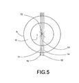
- the center of the circles formed by the object edges is determined by means of the edge matrix. To do this, one can interpret the pixels as mass points and determine the centroid of the mass points coincident with the midpoint, since the pixels on the circles are point symmetric to the center.
- Line profiles can be captured, with the line profiles specifying the elements of the edge matrix whose pixels lie on a straight line.
- One of the line profiles belonging to the line runs through the center of the circles formed by the object edges and the lines of the other line profiles run parallel to the straight line through the center and adjacent pixels through the center. Furthermore, the sum of the line profiles is formed.
- the device has an image processing device in the form of a digital camera and there are means for arranging the digital camera and the bobbin tube relative to one another such that a digital image of an end face of the cheese package can be detected.
- the device has an evaluation device which is designed to subject the digital image to edge detection in order to determine the object edges of the cheese package, to determine a detection parameter dependent on the width of the circular ring formed by the object edges, this detection parameter with one of the To compare sleeve parameters dependent reference value and to close depending on the comparison result on the orientation of the cheese package.
- processor units can be easily formed by software supplementation for carrying out the evaluation according to the invention.
- the device By own lighting, the device is largely independent of the influence of light.
- the Fig. 2 schematically shows an illustration of a device for determining the orientation of the bobbin 1.
- a digital camera 22 is arranged so that it can detect an end face 27 of the bobbin 1. In the present embodiment it is a black and white camera.
- the digital camera 22 is connected via a control line 25 to a control and evaluation unit 23. This triggers the image acquisition and carries out the edge detection and the determination of a recognition parameter.
- the control and evaluation unit 23 further controls a lighting device 24.
- the device is arranged so that the bobbin tubes are checked for their orientation before they are fed to the work stations of a cheese-producing textile machine.
- the control and evaluation unit 23 is connected to the other control units of the cross-wound textile machine, so that the bobbin tube can be aligned according to the determined orientation.
- FIGS. 3 and 4 each show an end face 27 of the bobbin 1.
- Die Fig. 3 shows the object edges of the tube tip 2.
- the annulus 10 has the outer diameter D, the inner diameter d 1 and the width b 1 .
- the Fig. 4 The circle edges 8 and 9 form the annulus 11.
- the outer diameter D is the with the Fig. 3 identical.
- the inner diameter d 2 is greater than the inner diameter d 1 at the tube tip 2.
- the width b 2 of the circular ring 11 on the sleeve foot 3 is smaller than the width b 1 of the circular ring 10 on the tube tip 2.
- the difference is in the beaded edge 4 founded on the sleeve tip 2. This difference makes use of the present invention. From the geometric dimensions, a recognition parameter K is calculated.
- a digital image is generated.
- This image is represented by a gray value matrix G with I rows and J columns, as given in equation (ii).
- Each element g i, j of the matrix represents one pixel.
- G G 0 . 0 G 0 . 1 G 0 . 2 G 0 . 3 ... G 0 . J - 1 G 0 . 0 G 0 . 0 G 0 . 0 G 0 . 0 G . 0 ... G 1 . J - 1 G 0 . 0 G 0 . 0 G 0 . 0 G 0 . 0 G 2 .
- the circle lines must be recognized.
- the image is subjected to edge detection.
- the object edge is where the change of the brightness is greatest.
- the change leads to the concept of derivative or for the two-dimensional image to the concept of the gradient. That is, for each point of the image, or in other words, for each point (i, j) of the gray value matrix G, the gradient ⁇ g (i, j) is calculated, as shown in equation (iii).
- ⁇ G i ⁇ j G ⁇ i . j + 1 - G ⁇ i . j - 1 G ⁇ i + 1 . j - G ⁇ i - 1 . j
- the gradient at location (i, j) is a vector.
- the first component of the vector indicates the change in the row direction and the second component indicates the change in the column direction.
- the magnitude of the gradient at location (i, j) defines a new matrix, the gradient matrix.
- the gradient matrix consists of I rows and J columns according to the gray value matrix.
- the pictorial representation results in an edge image, which is ideally the representation of the FIGS. 3 and 4 equivalent.
- the threshold value T can be calculated according to equation (vi) as a function of the maximum brightness value of the edge image.
- C T is a proportionality factor.
- T c T ⁇ Max G edge image i ⁇ j
- the threshold value matrix results in a threshold value image which has a stronger contrast to the edge image.
- the center of the circles forming the circular ring can first be determined. You can look at the pixels as mass points in a plane. Because the dots on the circles are point-symmetric to the center, center and center of gravity coincide.
- the masses m i correspond to the elements g SW (i, j) of the threshold value matrix.
- the reference numeral 12 carries.
- the straight line 13 passes through the center 12.
- the elements of the threshold value matrix whose pixels lie on this straight line define a line profile.
- further line profiles are determined. These are represented by the straight lines 14, 15, 16 and 17, which run parallel to the straight line 13 and through adjacent pixels.
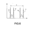
- the sum of the line profiles is formed. The course of this sum is in Fig. 6 shown.
- the maxima 18, 19, 20 and 21 represent the points of intersection of the straight lines 13, 14, 15, 16 and 17 with the circular lines 6 and 7. From this line profile profile can be determine in principle all geometric dimensions of the threshold value image, in particular the outer diameter D and the width b 1 of the circular ring.
- the outer diameter D results from the distance of the maxima 18 and 21.
- the width b 1 of the circular ring is represented by the distance between the maxima 18 and 19 and by the distance between the maxima 20 and 21.
- the reference value for the sleeve type used in each case is determined in advance in the present exemplary embodiment by calculating the mean value of the detection parameter of the sleeve tip and the sleeve foot. Each newly acquired recognition parameter is compared with the reference value. If the detection parameter is smaller than the reference value, then it is the tube tip. If the recognition parameter is greater than the reference value, then it is the case foot.
Landscapes
- Image Analysis (AREA)
- Length Measuring Devices By Optical Means (AREA)
- Storage Of Web-Like Or Filamentary Materials (AREA)
Applications Claiming Priority (1)
| Application Number | Priority Date | Filing Date | Title |
|---|---|---|---|
| DE102009058720A DE102009058720A1 (de) | 2009-12-17 | 2009-12-17 | Verfahren und Vorrichtung zur Ermittlung der Orientierung einer Kreuzspulenhülse |
Related Parent Applications (1)
| Application Number | Title | Priority Date | Filing Date |
|---|---|---|---|
| DE102009058720 Previously-Filed-Application | 2009-12-17 |
Publications (3)
| Publication Number | Publication Date |
|---|---|
| EP2336065A2 true EP2336065A2 (fr) | 2011-06-22 |
| EP2336065A3 EP2336065A3 (fr) | 2012-01-18 |
| EP2336065B1 EP2336065B1 (fr) | 2013-06-05 |
Family
ID=43607687
Family Applications (1)
| Application Number | Title | Priority Date | Filing Date |
|---|---|---|---|
| EP10014647.1A Not-in-force EP2336065B1 (fr) | 2009-12-17 | 2010-11-16 | Procédé et dispositif destinés à la détermination de l'orientation d'un tube de bobines croisées |
Country Status (4)
| Country | Link |
|---|---|
| US (1) | US8520890B2 (fr) |
| EP (1) | EP2336065B1 (fr) |
| CN (1) | CN102101610B (fr) |
| DE (1) | DE102009058720A1 (fr) |
Citations (3)
| Publication number | Priority date | Publication date | Assignee | Title |
|---|---|---|---|---|
| DE2412821A1 (de) | 1974-03-16 | 1975-09-18 | Hacoba Textilmaschinen | Vorrichtung zum automatischen zufuehren von spulenhuelsen |
| DE4341946A1 (de) | 1993-12-09 | 1995-06-14 | Schlafhorst & Co W | Vorrichtung zum lageorientierten Zuführen von zylindrischen Hülsen |
| DE19840299A1 (de) | 1998-09-04 | 2000-03-09 | Schlafhorst & Co W | Vorrichtung zur Erkennung der Orientierung von Kopsen |
Family Cites Families (9)
| Publication number | Priority date | Publication date | Assignee | Title |
|---|---|---|---|---|
| DE1560547A1 (de) * | 1963-09-07 | 1969-10-09 | Reiners Walter Dr Ing | Vorrichtung zum Gleichrichten von Spulen mit konischen Spulenhuelsen |
| SE458316B (sv) * | 1988-02-17 | 1989-03-13 | Inter Innovation Ab | Anordning foer kontroll av dokument |
| DE3912602A1 (de) * | 1989-04-17 | 1990-10-18 | Zinser Textilmaschinen Gmbh | Verfahren und vorrichtung zum ausrichten von spulenhuelsen mit verschiedenartig ausgebildeten endbereichen |
| IT1261814B (it) * | 1992-07-14 | 1996-06-03 | Murata Machinery Ltd | Metodo e dispositivo di ispezione di rocche di filo. |
| DE4421778C2 (de) * | 1994-06-22 | 1996-11-14 | Zinser Textilmaschinen Gmbh | Vorrichtung zum selbsttätigen Zu- oder Abführen voller Spulen oder leerer Hülsen für eine Textilmaschine |
| DE69705532T2 (de) * | 1997-03-19 | 2002-05-16 | Cognivision Research, S.L. | Verfahren zur überprüfung von textilspulen und vorrichtung für seine durchführung |
| DE19836071A1 (de) * | 1998-08-10 | 2000-02-17 | Schlafhorst & Co W | Verfahren zur Erkennung von Fadenresten auf Spinnkopshülsen |
| CN101192269B (zh) * | 2006-11-29 | 2012-05-02 | 佳能株式会社 | 从图像估计消失点的方法和装置、计算机程序及其存储介质 |
| CN101388020A (zh) * | 2008-07-07 | 2009-03-18 | 华南师范大学 | 一种基于内容的复合型图像检索方法 |
-
2009
- 2009-12-17 DE DE102009058720A patent/DE102009058720A1/de not_active Withdrawn
-
2010
- 2010-11-16 EP EP10014647.1A patent/EP2336065B1/fr not_active Not-in-force
- 2010-12-13 US US12/966,527 patent/US8520890B2/en not_active Expired - Fee Related
- 2010-12-17 CN CN201010594278.8A patent/CN102101610B/zh not_active Expired - Fee Related
Patent Citations (3)
| Publication number | Priority date | Publication date | Assignee | Title |
|---|---|---|---|---|
| DE2412821A1 (de) | 1974-03-16 | 1975-09-18 | Hacoba Textilmaschinen | Vorrichtung zum automatischen zufuehren von spulenhuelsen |
| DE4341946A1 (de) | 1993-12-09 | 1995-06-14 | Schlafhorst & Co W | Vorrichtung zum lageorientierten Zuführen von zylindrischen Hülsen |
| DE19840299A1 (de) | 1998-09-04 | 2000-03-09 | Schlafhorst & Co W | Vorrichtung zur Erkennung der Orientierung von Kopsen |
Also Published As
| Publication number | Publication date |
|---|---|
| CN102101610A (zh) | 2011-06-22 |
| EP2336065A3 (fr) | 2012-01-18 |
| EP2336065B1 (fr) | 2013-06-05 |
| DE102009058720A1 (de) | 2011-06-22 |
| CN102101610B (zh) | 2014-06-18 |
| US8520890B2 (en) | 2013-08-27 |
| US20110150281A1 (en) | 2011-06-23 |
Similar Documents
| Publication | Publication Date | Title |
|---|---|---|
| EP2883825B1 (fr) | Procédé de fonctionnement d'un bobinoir et bobinoir | |
| DE102016009151A1 (de) | Erfassungseinrichtung zur Erkennung von Fadenresten auf Spinnkopshülsen | |
| DE3008914C2 (fr) | ||
| DE102012019816A1 (de) | Verfahren zur Vorbereitung von Spinnkopsen, die auf Ringspinnmaschinen gefertigt wurden, für einen nachfolgenden Umspulvorgang | |
| DE102014016784A1 (de) | Erkennung von Fadenresten auf stehend angeordneten Spinnkopshülsen | |
| EP1047917B1 (fr) | Procede et dispositif pour mesurer la longueur de fibres | |
| DE102015004261A1 (de) | Verfahren zum Betreiben eines Verbundsystems aus mindestens einer Ringspinnmaschine und mindestens einer Spulmaschine sowie Verbundsystem | |
| EP2238062B1 (fr) | Procédé et dispositif de fabrication de bobines à enroulements croisés | |
| DE3872449T2 (de) | Verfahren zur ununterbrochenen fadenlieferung von spulen und vorrichtung zur durchfuehrung dieses verfahrens. | |
| DE102016121662A1 (de) | Verfahren und Vorrichtung zur Beurteilung der Qualität eines längsbewegten strangförmigen Gutes | |
| EP1685054B1 (fr) | Nettoyeur de file | |
| EP2336065B1 (fr) | Procédé et dispositif destinés à la détermination de l'orientation d'un tube de bobines croisées | |
| DE102013009653A1 (de) | Verfahren zum Einstellen einer Drehwinkelstellung eines eine Spulenhülse drehbeweglich halternden Spulenrahmens und Spulen herstellende Textilmaschine mit mehreren Spulstellen | |
| EP3770084A1 (fr) | Dispositif de stockage de boyaux de saucisses à surveillance de niveau de remplissage | |
| DE102018131264A1 (de) | Spulmaschine sowie Vorrichtung zur Erkennung von Fadenresten | |
| DE2149573A1 (de) | Vorrichtung zur ermittlung von spinnspulen, bei denen die laenge der aus dem wickel herausragenden huelsenenden ein vorgegebenes mindestmass unterschreitet | |
| WO2014085939A1 (fr) | Détermination des longueurs de pilosité d'un fil | |
| DE4110729A1 (de) | Vorrichtung zum ermitteln des fuellstandes von textilspulen, die eine einen fotooptischen detektor mit einer empfaengeroptik aufweisende messeinrichtung besitzt | |
| DE2024110C3 (de) | Verfahren und Vorrichtung zur Überwachung der Vorbereitung von Spinnkopsen für den Abspulvorgang | |
| EP3031760A1 (fr) | Procede et dispositif de fonctionnement d'un poste de travail d'une machine textile fabriquant des bobines croisees | |
| DE10256293B4 (de) | Verfahren und Vorrichtung zum Betreiben einer Arbeitsstelle einer Kreuzspulen herstellenden Textilmaschine | |
| DE4110626A1 (de) | Vorrichtung zum unterscheiden des bewicklungszustandes von kopsen | |
| EP3678868B1 (fr) | Dispositif d'impression directe pour l'application d'une image imprimée périphérique | |
| DE4428245B4 (de) | Vorrichtung zum Suchen des Fadenendes am Bewicklungskegel von Kopsen | |
| DE102021115565A1 (de) | Verfahren zur Optimierung der Taktleistung einer Kopsvorbereitungsstation eines Kreuzspulautomaten |
Legal Events
| Date | Code | Title | Description |
|---|---|---|---|
| PUAI | Public reference made under article 153(3) epc to a published international application that has entered the european phase |
Free format text: ORIGINAL CODE: 0009012 |
|
| AK | Designated contracting states |
Kind code of ref document: A2 Designated state(s): AL AT BE BG CH CY CZ DE DK EE ES FI FR GB GR HR HU IE IS IT LI LT LU LV MC MK MT NL NO PL PT RO RS SE SI SK SM TR |
|
| AX | Request for extension of the european patent |
Extension state: BA ME |
|
| PUAL | Search report despatched |
Free format text: ORIGINAL CODE: 0009013 |
|
| AK | Designated contracting states |
Kind code of ref document: A3 Designated state(s): AL AT BE BG CH CY CZ DE DK EE ES FI FR GB GR HR HU IE IS IT LI LT LU LV MC MK MT NL NO PL PT RO RS SE SI SK SM TR |
|
| AX | Request for extension of the european patent |
Extension state: BA ME |
|
| RIC1 | Information provided on ipc code assigned before grant |
Ipc: B65H 67/06 20060101AFI20111212BHEP |
|
| 17P | Request for examination filed |
Effective date: 20120718 |
|
| GRAP | Despatch of communication of intention to grant a patent |
Free format text: ORIGINAL CODE: EPIDOSNIGR1 |
|
| GRAS | Grant fee paid |
Free format text: ORIGINAL CODE: EPIDOSNIGR3 |
|
| GRAA | (expected) grant |
Free format text: ORIGINAL CODE: 0009210 |
|
| AK | Designated contracting states |
Kind code of ref document: B1 Designated state(s): AL AT BE BG CH CY CZ DE DK EE ES FI FR GB GR HR HU IE IS IT LI LT LU LV MC MK MT NL NO PL PT RO RS SE SI SK SM TR |
|
| REG | Reference to a national code |
Ref country code: GB Ref legal event code: FG4D Free format text: NOT ENGLISH |
|
| REG | Reference to a national code |
Ref country code: CH Ref legal event code: EP |
|
| REG | Reference to a national code |
Ref country code: AT Ref legal event code: REF Ref document number: 615568 Country of ref document: AT Kind code of ref document: T Effective date: 20130615 |
|
| REG | Reference to a national code |
Ref country code: IE Ref legal event code: FG4D Free format text: LANGUAGE OF EP DOCUMENT: GERMAN |
|
| REG | Reference to a national code |
Ref country code: DE Ref legal event code: R096 Ref document number: 502010003518 Country of ref document: DE Effective date: 20130801 |
|
| PG25 | Lapsed in a contracting state [announced via postgrant information from national office to epo] |
Ref country code: SE Free format text: LAPSE BECAUSE OF FAILURE TO SUBMIT A TRANSLATION OF THE DESCRIPTION OR TO PAY THE FEE WITHIN THE PRESCRIBED TIME-LIMIT Effective date: 20130605 Ref country code: SI Free format text: LAPSE BECAUSE OF FAILURE TO SUBMIT A TRANSLATION OF THE DESCRIPTION OR TO PAY THE FEE WITHIN THE PRESCRIBED TIME-LIMIT Effective date: 20130605 Ref country code: LT Free format text: LAPSE BECAUSE OF FAILURE TO SUBMIT A TRANSLATION OF THE DESCRIPTION OR TO PAY THE FEE WITHIN THE PRESCRIBED TIME-LIMIT Effective date: 20130605 Ref country code: GR Free format text: LAPSE BECAUSE OF FAILURE TO SUBMIT A TRANSLATION OF THE DESCRIPTION OR TO PAY THE FEE WITHIN THE PRESCRIBED TIME-LIMIT Effective date: 20130906 Ref country code: FI Free format text: LAPSE BECAUSE OF FAILURE TO SUBMIT A TRANSLATION OF THE DESCRIPTION OR TO PAY THE FEE WITHIN THE PRESCRIBED TIME-LIMIT Effective date: 20130605 Ref country code: NO Free format text: LAPSE BECAUSE OF FAILURE TO SUBMIT A TRANSLATION OF THE DESCRIPTION OR TO PAY THE FEE WITHIN THE PRESCRIBED TIME-LIMIT Effective date: 20130905 Ref country code: ES Free format text: LAPSE BECAUSE OF FAILURE TO SUBMIT A TRANSLATION OF THE DESCRIPTION OR TO PAY THE FEE WITHIN THE PRESCRIBED TIME-LIMIT Effective date: 20130916 |
|
| REG | Reference to a national code |
Ref country code: DE Ref legal event code: R081 Ref document number: 502010003518 Country of ref document: DE Owner name: SAURER SPINNING SOLUTIONS GMBH & CO. KG, DE Free format text: FORMER OWNER: OERLIKON TEXTILE GMBH & CO. KG, 42897 REMSCHEID, DE Effective date: 20130918 Ref country code: DE Ref legal event code: R081 Ref document number: 502010003518 Country of ref document: DE Owner name: SAURER GERMANY GMBH & CO. KG, DE Free format text: FORMER OWNER: OERLIKON TEXTILE GMBH & CO. KG, 42897 REMSCHEID, DE Effective date: 20130918 |
|
| REG | Reference to a national code |
Ref country code: NL Ref legal event code: VDEP Effective date: 20130605 |
|
| REG | Reference to a national code |
Ref country code: LT Ref legal event code: MG4D |
|
| PG25 | Lapsed in a contracting state [announced via postgrant information from national office to epo] |
Ref country code: RS Free format text: LAPSE BECAUSE OF FAILURE TO SUBMIT A TRANSLATION OF THE DESCRIPTION OR TO PAY THE FEE WITHIN THE PRESCRIBED TIME-LIMIT Effective date: 20130605 Ref country code: HR Free format text: LAPSE BECAUSE OF FAILURE TO SUBMIT A TRANSLATION OF THE DESCRIPTION OR TO PAY THE FEE WITHIN THE PRESCRIBED TIME-LIMIT Effective date: 20130605 Ref country code: BG Free format text: LAPSE BECAUSE OF FAILURE TO SUBMIT A TRANSLATION OF THE DESCRIPTION OR TO PAY THE FEE WITHIN THE PRESCRIBED TIME-LIMIT Effective date: 20130905 |
|
| PG25 | Lapsed in a contracting state [announced via postgrant information from national office to epo] |
Ref country code: LV Free format text: LAPSE BECAUSE OF FAILURE TO SUBMIT A TRANSLATION OF THE DESCRIPTION OR TO PAY THE FEE WITHIN THE PRESCRIBED TIME-LIMIT Effective date: 20130605 |
|
| PG25 | Lapsed in a contracting state [announced via postgrant information from national office to epo] |
Ref country code: SK Free format text: LAPSE BECAUSE OF FAILURE TO SUBMIT A TRANSLATION OF THE DESCRIPTION OR TO PAY THE FEE WITHIN THE PRESCRIBED TIME-LIMIT Effective date: 20130605 Ref country code: PT Free format text: LAPSE BECAUSE OF FAILURE TO SUBMIT A TRANSLATION OF THE DESCRIPTION OR TO PAY THE FEE WITHIN THE PRESCRIBED TIME-LIMIT Effective date: 20131007 Ref country code: IS Free format text: LAPSE BECAUSE OF FAILURE TO SUBMIT A TRANSLATION OF THE DESCRIPTION OR TO PAY THE FEE WITHIN THE PRESCRIBED TIME-LIMIT Effective date: 20131005 Ref country code: EE Free format text: LAPSE BECAUSE OF FAILURE TO SUBMIT A TRANSLATION OF THE DESCRIPTION OR TO PAY THE FEE WITHIN THE PRESCRIBED TIME-LIMIT Effective date: 20130605 |
|
| PG25 | Lapsed in a contracting state [announced via postgrant information from national office to epo] |
Ref country code: RO Free format text: LAPSE BECAUSE OF FAILURE TO SUBMIT A TRANSLATION OF THE DESCRIPTION OR TO PAY THE FEE WITHIN THE PRESCRIBED TIME-LIMIT Effective date: 20130605 Ref country code: PL Free format text: LAPSE BECAUSE OF FAILURE TO SUBMIT A TRANSLATION OF THE DESCRIPTION OR TO PAY THE FEE WITHIN THE PRESCRIBED TIME-LIMIT Effective date: 20130605 Ref country code: NL Free format text: LAPSE BECAUSE OF FAILURE TO SUBMIT A TRANSLATION OF THE DESCRIPTION OR TO PAY THE FEE WITHIN THE PRESCRIBED TIME-LIMIT Effective date: 20130605 |
|
| PLBE | No opposition filed within time limit |
Free format text: ORIGINAL CODE: 0009261 |
|
| STAA | Information on the status of an ep patent application or granted ep patent |
Free format text: STATUS: NO OPPOSITION FILED WITHIN TIME LIMIT |
|
| PG25 | Lapsed in a contracting state [announced via postgrant information from national office to epo] |
Ref country code: DK Free format text: LAPSE BECAUSE OF FAILURE TO SUBMIT A TRANSLATION OF THE DESCRIPTION OR TO PAY THE FEE WITHIN THE PRESCRIBED TIME-LIMIT Effective date: 20130605 |
|
| 26N | No opposition filed |
Effective date: 20140306 |
|
| BERE | Be: lapsed |
Owner name: OERLIKON TEXTILE G.M.B.H. & CO. KG Effective date: 20131130 |
|
| REG | Reference to a national code |
Ref country code: DE Ref legal event code: R097 Ref document number: 502010003518 Country of ref document: DE Effective date: 20140306 |
|
| PG25 | Lapsed in a contracting state [announced via postgrant information from national office to epo] |
Ref country code: MC Free format text: LAPSE BECAUSE OF FAILURE TO SUBMIT A TRANSLATION OF THE DESCRIPTION OR TO PAY THE FEE WITHIN THE PRESCRIBED TIME-LIMIT Effective date: 20130605 |
|
| REG | Reference to a national code |
Ref country code: FR Ref legal event code: ST Effective date: 20140731 |
|
| REG | Reference to a national code |
Ref country code: IE Ref legal event code: MM4A |
|
| PG25 | Lapsed in a contracting state [announced via postgrant information from national office to epo] |
Ref country code: BE Free format text: LAPSE BECAUSE OF NON-PAYMENT OF DUE FEES Effective date: 20131130 |
|
| PG25 | Lapsed in a contracting state [announced via postgrant information from national office to epo] |
Ref country code: IE Free format text: LAPSE BECAUSE OF NON-PAYMENT OF DUE FEES Effective date: 20131116 |
|
| PG25 | Lapsed in a contracting state [announced via postgrant information from national office to epo] |
Ref country code: FR Free format text: LAPSE BECAUSE OF NON-PAYMENT OF DUE FEES Effective date: 20131202 |
|
| PG25 | Lapsed in a contracting state [announced via postgrant information from national office to epo] |
Ref country code: SM Free format text: LAPSE BECAUSE OF FAILURE TO SUBMIT A TRANSLATION OF THE DESCRIPTION OR TO PAY THE FEE WITHIN THE PRESCRIBED TIME-LIMIT Effective date: 20130605 |
|
| PG25 | Lapsed in a contracting state [announced via postgrant information from national office to epo] |
Ref country code: CY Free format text: LAPSE BECAUSE OF FAILURE TO SUBMIT A TRANSLATION OF THE DESCRIPTION OR TO PAY THE FEE WITHIN THE PRESCRIBED TIME-LIMIT Effective date: 20130605 Ref country code: TR Free format text: LAPSE BECAUSE OF FAILURE TO SUBMIT A TRANSLATION OF THE DESCRIPTION OR TO PAY THE FEE WITHIN THE PRESCRIBED TIME-LIMIT Effective date: 20130605 |
|
| REG | Reference to a national code |
Ref country code: CH Ref legal event code: PL |
|
| GBPC | Gb: european patent ceased through non-payment of renewal fee |
Effective date: 20141116 |
|
| PG25 | Lapsed in a contracting state [announced via postgrant information from national office to epo] |
Ref country code: LI Free format text: LAPSE BECAUSE OF NON-PAYMENT OF DUE FEES Effective date: 20141130 Ref country code: CH Free format text: LAPSE BECAUSE OF NON-PAYMENT OF DUE FEES Effective date: 20141130 Ref country code: MK Free format text: LAPSE BECAUSE OF FAILURE TO SUBMIT A TRANSLATION OF THE DESCRIPTION OR TO PAY THE FEE WITHIN THE PRESCRIBED TIME-LIMIT Effective date: 20130605 Ref country code: HU Free format text: LAPSE BECAUSE OF FAILURE TO SUBMIT A TRANSLATION OF THE DESCRIPTION OR TO PAY THE FEE WITHIN THE PRESCRIBED TIME-LIMIT; INVALID AB INITIO Effective date: 20101116 Ref country code: LU Free format text: LAPSE BECAUSE OF NON-PAYMENT OF DUE FEES Effective date: 20131116 |
|
| PG25 | Lapsed in a contracting state [announced via postgrant information from national office to epo] |
Ref country code: MT Free format text: LAPSE BECAUSE OF FAILURE TO SUBMIT A TRANSLATION OF THE DESCRIPTION OR TO PAY THE FEE WITHIN THE PRESCRIBED TIME-LIMIT Effective date: 20130605 |
|
| PG25 | Lapsed in a contracting state [announced via postgrant information from national office to epo] |
Ref country code: GB Free format text: LAPSE BECAUSE OF NON-PAYMENT OF DUE FEES Effective date: 20141116 |
|
| REG | Reference to a national code |
Ref country code: AT Ref legal event code: MM01 Ref document number: 615568 Country of ref document: AT Kind code of ref document: T Effective date: 20151116 |
|
| PG25 | Lapsed in a contracting state [announced via postgrant information from national office to epo] |
Ref country code: AT Free format text: LAPSE BECAUSE OF NON-PAYMENT OF DUE FEES Effective date: 20151116 |
|
| REG | Reference to a national code |
Ref country code: DE Ref legal event code: R081 Ref document number: 502010003518 Country of ref document: DE Owner name: SAURER SPINNING SOLUTIONS GMBH & CO. KG, DE Free format text: FORMER OWNER: SAURER GERMANY GMBH & CO. KG, 42897 REMSCHEID, DE |
|
| PG25 | Lapsed in a contracting state [announced via postgrant information from national office to epo] |
Ref country code: AL Free format text: LAPSE BECAUSE OF FAILURE TO SUBMIT A TRANSLATION OF THE DESCRIPTION OR TO PAY THE FEE WITHIN THE PRESCRIBED TIME-LIMIT Effective date: 20130605 |
|
| PGFP | Annual fee paid to national office [announced via postgrant information from national office to epo] |
Ref country code: IT Payment date: 20231129 Year of fee payment: 14 Ref country code: DE Payment date: 20231121 Year of fee payment: 14 Ref country code: CZ Payment date: 20231024 Year of fee payment: 14 |
|
| REG | Reference to a national code |
Ref country code: DE Ref legal event code: R119 Ref document number: 502010003518 Country of ref document: DE |
|
| PG25 | Lapsed in a contracting state [announced via postgrant information from national office to epo] |
Ref country code: CZ Free format text: LAPSE BECAUSE OF NON-PAYMENT OF DUE FEES Effective date: 20241116 |
|
| PG25 | Lapsed in a contracting state [announced via postgrant information from national office to epo] |
Ref country code: DE Free format text: LAPSE BECAUSE OF NON-PAYMENT OF DUE FEES Effective date: 20250603 |
|
| PG25 | Lapsed in a contracting state [announced via postgrant information from national office to epo] |
Ref country code: IT Free format text: LAPSE BECAUSE OF NON-PAYMENT OF DUE FEES Effective date: 20241116 |