EP2336408A2 - Tendeur de fil pour broche de métier à retordre à double torsion - Google Patents
Tendeur de fil pour broche de métier à retordre à double torsion Download PDFInfo
- Publication number
- EP2336408A2 EP2336408A2 EP10014265A EP10014265A EP2336408A2 EP 2336408 A2 EP2336408 A2 EP 2336408A2 EP 10014265 A EP10014265 A EP 10014265A EP 10014265 A EP10014265 A EP 10014265A EP 2336408 A2 EP2336408 A2 EP 2336408A2
- Authority
- EP
- European Patent Office
- Prior art keywords
- brake
- thread
- piston
- braking
- yarn
- Prior art date
- Legal status (The legal status is an assumption and is not a legal conclusion. Google has not performed a legal analysis and makes no representation as to the accuracy of the status listed.)
- Granted
Links
Images




Classifications
-
- D—TEXTILES; PAPER
- D01—NATURAL OR MAN-MADE THREADS OR FIBRES; SPINNING
- D01H—SPINNING OR TWISTING
- D01H13/00—Other common constructional features, details or accessories
- D01H13/10—Tension devices
- D01H13/104—Regulating tension by devices acting on running yarn and not associated with supply or take-up devices
- D01H13/106—Regulating tension by devices acting on running yarn and not associated with supply or take-up devices for double-twist spindle
Definitions
- the invention relates to a yarn brake for a double twisting spindle according to the preamble of claim 1.
- Thread brakes for double twisting spindles have long been known in various embodiments and described in detail in numerous patents in part.
- Such thread brakes are used in particular in double-twisting processes and ensure that the thread receives a certain bias during the twisting process.
- a double-twisting spindle with a thread brake is known, which is designed as a brake cartridge.
- yarn brakes are based on two telescopically sliding, apart by a spring element cylinder with their spherical ends on braking surfaces, which are arranged in the region of a thread inlet opening or a Fadenauslassö réelle a brake housing and thereby clamp the continuous thread.
- a disadvantage of such brake cartridges is that the bias of the yarn during the twisting process is determined only by the spring force of the spring element of the brake cartridge, and, at least during the twisting process, can not be corrected. Furthermore, for example by the DE 33 36 715 C2 or the US 7,000,865 B1 Braking devices for double twisting spindles known, each having a ball which rests in a brake housing on a braking surface.
- the braking force acting on the continuous thread is dependent on the weight of the ball, that is, the bias of the thread can be adjusted to a certain extent on the diameter of the ball.
- the DE 197 55 825 A1 describes a double twisting spindle for twisting natural silk, the yarn brake has a total of seven successively arranged Bremskugel sensibleen.
- Such braking devices not only require a relatively large installation space, but are also with respect to the threading of a new thread extremely disadvantageous.
- the pretension of the spring element and thus the contact pressure of the brake ball can be set defined on the braking surfaces.
- the brake ball can be lifted pneumatically, which greatly facilitates the threading of a new thread in the yarn brake.
- a disadvantage of this type of yarn brake is that the spring-loaded piston, which has the upper braking surface slides almost without play in an axial guidance of the yarn brake housing.
- the upper braking surface can not escape laterally, which leads to Fadenanom procheen, such as knots, thick spots, dust particles, etc. lead to strong thread tension increases up to thread breakages.
- the present invention seeks to develop a yarn brake for a double twisting spindle, which is designed so that they avoid thread tension increases that could lead to a yarn breakage, as far as possible.
- the inventive construction of the thread brake wherein the upper brake surface receiving upper piston is formed and guided with play within a housing of the thread brake that he can dodge if necessary in a position in which its central longitudinal axis with the central longitudinal axis of the housing an angle has the advantage that the upper piston automatically responds to thread abnormalities.
- the angle which is set at the occurrence of Fadenanom procheen between the central longitudinal axis of the upper piston and the central longitudinal axis of the housing of the yarn brake, up to 10 °.
- Such a relatively small tilt angle minimizes the constructive effort in the area of the thread brake, but nevertheless ensures that the occurrence of high thread tensions when overflowing the upper braking surface is prevented by, for example, knots, thick spots or dust buffs.
- the escape of the upper piston is made possible in the event of yarn abnormalities in that the upper piston is provided with guide lugs, which allow a certain lateral displacement of the piston.
- the upper piston has, for example, a disc-shaped lower guide lug whose diameter is below the inner diameter of the housing in the working area of the guide lug (Anspr.3).
- the upper piston has a preferably circular upper guide surface whose inner diameter is above the outer diameter of the hollow axis of the double-wire spindle (Anspr.4).
- At least the disc-shaped lower guide lug in an advantageous embodiment, a convex curved, circumferential guide surface.
- a convexly curved guide surface on the one hand favors the tiltability of the piston and on the other hand reliably prevents the piston from becoming jammed in the housing.
- a convex curved, circumferential guide surface has a positive effect on the function of the thread brake if necessary.
- the upper piston is acted upon by two spring elements arranged one behind the other, each having different spring characteristics and their bias, as defined in claim 7, defined adjustable via a rotatably mounted abutment device.
- the abutment device has wendelartig arranged detent positions, which are easily ingested by appropriate rotation of the abutment device in the housing of the yarn brake.
- the lower braking surface to which the braking element is pressed integrated in a lower piston, which is acted upon by a spring element, positioned in a working position and pneumatically for threading a new thread is lowered into a threading position.
- Such a design facilitates the threading of a new thread, especially in combination with one of the devices described in claims 9 - 11 and 12, respectively.
- a limited axially movable support element is arranged in the region of the brake element. This support element is positioned during the twisting operation by the lower piston in a rest position and slides when lowering the lower piston in its threading position in an intermediate position.
- the support member also has, as set forth in claim 10, for guiding the braking element on an inclined plane.
- the off-center position is defined by a receiving pocket, which, as set forth in claim 11, is embedded in the lower piston.
- the braking member has when threading a new thread with neither the upper braking surface, still with the lower braking surface contact, but is, spaced from the braking surfaces and outside the threadline of new threads, in a receiving pocket of the lower piston.
- a support element to be installed on the housing in the region of the brake element. On this stationary support element sets when lowering the lower piston in its threading the brake element.
- the support element is designed so that even with the brake element resting between the support element and brake element sufficient space is available, so that it is ensured even in this embodiment that new threads can be easily threaded.
- both the braking element formed as a brake ball, and the braking surfaces are made of a material that is very resistant to abrasion.
- the brake ball and / or the braking surfaces may, for example, as set forth in claim 13, made of hardened steel, which is a relatively inexpensive construction, or the brake ball and / or the braking surfaces, as described in claim 14, from an oxide ceramic Be made of material.
- Such oxide-ceramic materials are known to have a high hardness and are correspondingly very wear-resistant.
- the Fig.1 shows schematically, partially in section, a total designated by the reference numeral 1 double twisting spindle. With such a double-twisting spindle 1, one or more threads are given rotation.
- This rotation pitch serves to increase the quality of the thread (s), for example, in terms of tear strength and so that the better processability in subsequent processes, such as weaving, knitting, tufting and the like.
- the threads 3 and 4 are twisted by a rotatably mounted spindle part 6, which is disposed below the protective pot 9, L-shaped deflected and get, preferably on a functioning as a balloon restrictor sheath 7, in balloon form upward sliding, to a stationary balloon yarn guide 8, to then be wound on a winding device 10, as now verzwirnter thread 15 to a coil 11.
- the spindle part 6 in the exemplary embodiment at the end a whorl 12, which is acted upon by a tangential belt 13 frictionally in the sense of rotation.
- a thread brake 14 according to the invention is also installed in the region of the hollow shaft 5 of the double-twisting spindle 1, which pre-brakes the continuous threads 3, 4.
- Such preliminary braking is necessary in order to be able to form a thread reserve in the region of a storage part of the spindle part 6, which is necessary for a trouble-free twisting process.
- FIGS. 2A and 2 B show a first advantageous embodiment of the yarn brake 14 according to the invention in a larger scale and in detail.
- the Fig. 2A shows the yarn brake 14 with a positioned in working position A braking element 29, while the Fig. 2B the yarn brake 14 in threading position E shows.
- the thread brake 14 has a tubular housing 16, which is provided both on its upper side, as well as on its underside each with a (unspecified) screw internal thread.
- a cover 17 which on the one hand forms a guide for the hollow axle 5 and, on the other hand, an abutment for a first spring element 18 arranged inside the cover 17, is fastened in the housing 16 via the upper screw internal thread.
- This first spring element 18 acts on a pot-shaped trained, guided on the inner wall of the housing 16 abutment element 19 of the hollow shaft 5, which in turn is equipped with a plurality of helically arranged locking positions 20.
- one of the helically arranged locking positions 20 can be positioned on the stationary cam 21 by appropriate rotation of the hollow shaft 5 and thus the axial position of the abutment element 19 in the housing 16 can be adjusted.
- the braking force of the yarn brake 14 can be set defined.
- a spring element 23 is arranged, which corresponds to a sleeve 22, which in turn is guided on the inner wall of the abutment member 19.
- the spring element 24 is also turned on.
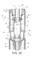
- the upper piston 27 is mounted via guide lugs 25, 26 within the housing 16 of the thread brake 14, wherein the upper piston 27 is equipped both with a lower guide lug 25 whose outer diameter d, as in 3A shown under the
- Inner diameter D of the housing 16 in the working range of the piston 27 is located, as well as an upper guide lug 26 has, whose inner diameter d 1 is greater than the outer diameter D 1 of the hollow shaft. 5
- the upper piston 27 is supported both in the region of the upper, as well as in the region of the lower guide lug with game S.
- a ring-like insert made of a wear-resistant material, for example hardened steel or an oxide-ceramic material, is fixed on the upper piston 27 and forms an upper braking surface 28 in conjunction with a brake element 29, preferably a brake ball.
- the brake ball 29, which is preferably also made of a wear-resistant material, is, acted upon by the spring force of the spring elements 23, 24 described above, also on a lower braking surface 30.
- the lower braking surface 30 is preferably designed as a ring-like insert and made of hardened steel or an oxide-ceramic material.
- the lower braking surface 30 is arranged in a lower piston 31, which is positioned during the twisting process by a fourth spring element 33 in its working position A and has a lower hollow shaft 32.
- the lower piston 31 positioning spring element 33 is supported on an intermediate insert 34 which is fixed in the lower screw internal thread of the housing 16, and in turn receives a cover member 35 in which a selectively controllable pneumatic cylinder 36 is mounted.
- the Fig. 3B shows the yarn brake 14 according to the invention during the "normal" twisting process.
- the introduced into the hollow shaft 5 of the double-twisting spindle 1 threads 3, 4 are acted on the one hand in the region of the upper braking surface 28 and on the other hand in the region of the lower braking surface 29 by the brake ball 29 with a predetermined braking force and thus provided with a necessary for the twisting process bias.
- the threads twisted into a thread 15 leave the thread brake 14 through the lower hollow axle 32 of the lower piston 31.
- the upper piston 27 supported by play S in the housing 16 is slightly tilted by the threads 3, 4 running over the upper braking surface 28.
- the braking surface 28 differs slightly laterally, so that a certain, relatively small angle ⁇ is established between the central longitudinal axis 37 of the upper piston 27 and the central longitudinal axis 38 of the housing 16, on the one hand by the thread thickness of the threads 3, 4 and on the other hand depends on the respective thread condition.
- the upper braking surface 28 is also raised by an amount V, depending on the thickness of the node 41.
- the thread brake 14 for threading new threads 3, 4 also be opened.
- the lower piston 31 and thus the lower braking surface 30 can be lowered by appropriate actuation of the pneumatic piston 36 against the force of the spring element 33 from the working position A in the threading position E.
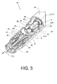
- the brake ball 29 detaches from the upper braking surface 28 and then slides, depending on the embodiment, either, as in Fig. 2B represented, on the inclined plane 44 of the support element 2 in a receiving pocket 45 in the lower piston 31 or the brake ball 29 comes, as in Fig. 5 shown slightly spaced from the upper braking surface 28 on a support element 42a for support, which is part of the housing 16.
- the lower braking surface 30 is positioned so that upon application of a negative pressure to the output of the double twisting spindle 1 in the hollow axes 5 and 32 of the yarn brake 14, a negative pressure flow 43 sets, which is easy threading new threads 3, 4 in the thread brake 14 allows.
- spring elements 18, 23, 24, 33 it should be noted that preferably spring elements are used which have different characteristics. However, spring elements can be used which have the same characteristics.
- spring elements can either be used in series operation as set out in the present exemplary embodiments, or else in parallel operation.
- the resulting braking force curve can also be designed to suit requirements.
- the resulting braking force characteristic can, for example, be linear, degressive, progressive, etc.
Landscapes
- Engineering & Computer Science (AREA)
- Mechanical Engineering (AREA)
- Textile Engineering (AREA)
- Spinning Or Twisting Of Yarns (AREA)
Applications Claiming Priority (1)
| Application Number | Priority Date | Filing Date | Title |
|---|---|---|---|
| DE102009058979A DE102009058979A1 (de) | 2009-12-18 | 2009-12-18 | Fadenbremse für eine Doppeldrahtzwirnspindel |
Related Parent Applications (1)
| Application Number | Title | Priority Date | Filing Date |
|---|---|---|---|
| DE102009058979 Previously-Filed-Application | 2009-12-18 |
Publications (3)
| Publication Number | Publication Date |
|---|---|
| EP2336408A2 true EP2336408A2 (fr) | 2011-06-22 |
| EP2336408A3 EP2336408A3 (fr) | 2014-04-02 |
| EP2336408B1 EP2336408B1 (fr) | 2015-06-10 |
Family
ID=43899653
Family Applications (1)
| Application Number | Title | Priority Date | Filing Date |
|---|---|---|---|
| EP10014265.2A Active EP2336408B1 (fr) | 2009-12-18 | 2010-11-03 | broche de métier à retordre à double torsion comprenant un tendeur de fil |
Country Status (4)
| Country | Link |
|---|---|
| US (1) | US8256201B2 (fr) |
| EP (1) | EP2336408B1 (fr) |
| CN (1) | CN102102251B (fr) |
| DE (1) | DE102009058979A1 (fr) |
Families Citing this family (5)
| Publication number | Priority date | Publication date | Assignee | Title |
|---|---|---|---|---|
| CN103541075A (zh) * | 2013-09-26 | 2014-01-29 | 吴江伊莱纺织科技有限公司 | 一种可精确调节的纱线张力器 |
| DE102015118878B3 (de) * | 2015-11-04 | 2017-03-16 | Saurer Germany Gmbh & Co. Kg | Kugelfadenbremse für eine Doppeldraht-Zwirnspindel |
| DE102015118871B3 (de) * | 2015-11-04 | 2017-03-16 | Saurer Germany Gmbh & Co. Kg | Kugelfadenbremse für eine Doppeldraht-Zwirnspindel |
| DE102015014299A1 (de) | 2015-11-06 | 2017-05-11 | Saurer Germany Gmbh & Co. Kg | Außenfadenbremse, Kordier- oder Kabliermaschine mit einer Außenfadenbremse und Verfahren zum Betreiben einer solchen Kordier- oder Kabliermaschine |
| CN110592749B (zh) * | 2019-09-25 | 2021-05-11 | 北京卓文时尚纺织股份有限公司 | 一种捻线机 |
Citations (4)
| Publication number | Priority date | Publication date | Assignee | Title |
|---|---|---|---|---|
| DE3139236A1 (de) | 1980-10-08 | 1982-05-13 | Barmag Barmer Maschinenfabrik Ag, 5630 Remscheid | "doppeldrahtzwirnspindel mit einer bremspatrone" |
| DE3336715C2 (de) | 1983-10-08 | 1986-03-20 | Palitex Project-Company Gmbh, 4150 Krefeld | Fadenbremse |
| DE19755825C1 (de) | 1997-12-16 | 1999-02-18 | Peter Mueller | Propeller mit einstellbarer Flügelsteigung, insbes. für Sportboote |
| US7000865B1 (en) | 2003-08-28 | 2006-02-21 | Zollinger Richard V | Snap-on ball tensioning device |
Family Cites Families (14)
| Publication number | Priority date | Publication date | Assignee | Title |
|---|---|---|---|---|
| US3945184A (en) * | 1975-04-04 | 1976-03-23 | Palitex Project Company Gmbh | Self-threading yarn brake mechanism in a hollow spindle assembly of a textile yarn processing machine |
| DE2830265C2 (de) * | 1978-07-10 | 1983-01-13 | Palitex Project-Company Gmbh, 4150 Krefeld | Doppeldraht-Zwirnspindel |
| US4355500A (en) * | 1979-07-23 | 1982-10-26 | Murata Kikai Kabushiki Kaisha | Pneumatic yarn guiding apparatus for double twisting machine |
| FR2493353A1 (fr) * | 1980-11-03 | 1982-05-07 | Verdol Sa | Dispositif d'enfilage pneumatique d'un fil dans une broche a double torsion |
| DE8110891U1 (de) | 1981-04-10 | 1982-06-24 | Barmag Barmer Maschinenfabrik Ag, 5630 Remscheid | Doppeldrahtzwirnspindel |
| JPS5943403Y2 (ja) * | 1982-12-28 | 1984-12-22 | 村田機械株式会社 | 二重撚糸機におけるテンシヨン装置 |
| DE3580919D1 (de) * | 1985-10-15 | 1991-01-24 | Murata Machinery Ltd | Vorrichtung zum zurueckziehen eines fadenspanners an einer doppeldrahtzwirnspindel. |
| DE3605193C1 (de) * | 1986-02-19 | 1987-07-09 | Palitex Project Co Gmbh | Fadenbremse fuer Zwirnmaschinen,insbesondere Doppeldraht-Zwirnmaschinen |
| CS277095B6 (en) * | 1990-04-24 | 1992-11-18 | Elitex Zavody Textilniho | Thread brake on a two-for-one twisting frame spindle |
| DE4103286C2 (de) * | 1991-02-04 | 1993-10-28 | Palitex Project Co Gmbh | Doppeldraht-Zwirnspindel |
| DE4343458C2 (de) * | 1993-12-20 | 1996-09-05 | Palitex Project Co Gmbh | Fadenbremse, insbesondere für Doppeldraht-Zwirnspindeln |
| DE10032141A1 (de) * | 2000-07-01 | 2002-01-17 | Volkmann Gmbh | Fadenbremse und mit einer solchen Fadenbremse ausgerüstete Spindeln, Doppeldraht-Zwirnspindeln und Doppeldraht-Zwirnmaschinen |
| DE10032140A1 (de) * | 2000-07-01 | 2002-01-17 | Volkmann Gmbh | Fadenbremse und mit einer solchen Fadenbremse ausgerüstete Spindeln, Doppeldraht-Zwirnspindeln und Doppeldraht-Zwirnmaschinen |
| DE102007023143B4 (de) * | 2007-05-16 | 2021-05-12 | Saurer Technologies GmbH & Co. KG | Federbelastete Fadenbremse |
-
2009
- 2009-12-18 DE DE102009058979A patent/DE102009058979A1/de not_active Withdrawn
-
2010
- 2010-11-03 EP EP10014265.2A patent/EP2336408B1/fr active Active
- 2010-12-08 US US12/962,715 patent/US8256201B2/en not_active Expired - Fee Related
- 2010-12-13 CN CN201010586777.2A patent/CN102102251B/zh not_active Expired - Fee Related
Patent Citations (4)
| Publication number | Priority date | Publication date | Assignee | Title |
|---|---|---|---|---|
| DE3139236A1 (de) | 1980-10-08 | 1982-05-13 | Barmag Barmer Maschinenfabrik Ag, 5630 Remscheid | "doppeldrahtzwirnspindel mit einer bremspatrone" |
| DE3336715C2 (de) | 1983-10-08 | 1986-03-20 | Palitex Project-Company Gmbh, 4150 Krefeld | Fadenbremse |
| DE19755825C1 (de) | 1997-12-16 | 1999-02-18 | Peter Mueller | Propeller mit einstellbarer Flügelsteigung, insbes. für Sportboote |
| US7000865B1 (en) | 2003-08-28 | 2006-02-21 | Zollinger Richard V | Snap-on ball tensioning device |
Also Published As
| Publication number | Publication date |
|---|---|
| EP2336408A3 (fr) | 2014-04-02 |
| CN102102251B (zh) | 2015-01-07 |
| CN102102251A (zh) | 2011-06-22 |
| EP2336408B1 (fr) | 2015-06-10 |
| US20110146221A1 (en) | 2011-06-23 |
| US8256201B2 (en) | 2012-09-04 |
| DE102009058979A1 (de) | 2011-06-22 |
Similar Documents
| Publication | Publication Date | Title |
|---|---|---|
| EP2336408B1 (fr) | broche de métier à retordre à double torsion comprenant un tendeur de fil | |
| DE4411002A1 (de) | Gerät zum Schneiden von Pflanzen | |
| EP0165428A2 (fr) | Machine textile avec plusieurs unités de bobinage de fil à vitesse constante sur bobine conique | |
| DE2050490A1 (de) | Fadenbremsvorrichtung an Doppeldrahtzwirnspindeln | |
| DE1435219C3 (de) | Klöppel für Flechtmaschinen, insbesondere Schlauchumflechtungsmaschinen | |
| DE102005035049A1 (de) | Spinnvorrichtung zur Herstellung eines gesponnenen Fadens mittels eines umlaufenden Luftstroms | |
| DE2831532A1 (de) | Vorrichtung zur pneumatischen einfaedelung eines fadens in die bohrung einer spindel | |
| DE4408262C2 (de) | Einrichtung zum Einstellen von Kapselfadenbremsen an Zwirnmaschinen, insbesondere Doppeldraht-Zwirnmaschinen | |
| DE1710049A1 (de) | Spinn- und Zwirnvorrichtung | |
| AT396486B (de) | Garntexturierdüse | |
| DE3017837C2 (de) | Hubvorrichtung für eine Ringbank und eine Bank für Balloneinengungsringe | |
| DE4235203A1 (de) | Spinnereivorrichtung | |
| DE1160340B (de) | Doppeldrahtzwirnspindel mit Fadenspeicherrinne und im Fadenlauf vor dieser liegenden Fadenbremse | |
| DE3408515C2 (fr) | ||
| EP0031843B2 (fr) | Flyer pour banc a broches | |
| DE2130960A1 (de) | Falschdrallverfahren und -vorrichtung zum Drehen von Textilfaeden | |
| DE1560420A1 (de) | Garn-Spannvorrichtung | |
| DE4010018C2 (de) | Spindel zum Herstellen eines Fadens | |
| DE202007012066U1 (de) | Coregarn-Einrichtung und Spulenseparator | |
| DE102015118871B3 (de) | Kugelfadenbremse für eine Doppeldraht-Zwirnspindel | |
| DE102014002882A1 (de) | Arbeitsstelle einer Textilmaschine mit einer Paraffinierungseinrichtung | |
| DE102015118878B3 (de) | Kugelfadenbremse für eine Doppeldraht-Zwirnspindel | |
| DE3913794A1 (de) | Aufwickeleinheit und -anordnung | |
| DE2921414C2 (de) | Angetriebenes Fadenführungsorgan zur Herstellung einer Fadenreserve | |
| DE1510847C3 (de) | Federnd nachgiebige Fadenbremse |
Legal Events
| Date | Code | Title | Description |
|---|---|---|---|
| PUAI | Public reference made under article 153(3) epc to a published international application that has entered the european phase |
Free format text: ORIGINAL CODE: 0009012 |
|
| AK | Designated contracting states |
Kind code of ref document: A2 Designated state(s): AL AT BE BG CH CY CZ DE DK EE ES FI FR GB GR HR HU IE IS IT LI LT LU LV MC MK MT NL NO PL PT RO RS SE SI SK SM TR |
|
| AX | Request for extension of the european patent |
Extension state: BA ME |
|
| RAP1 | Party data changed (applicant data changed or rights of an application transferred) |
Owner name: SAURER GERMANY GMBH & CO. KG |
|
| PUAL | Search report despatched |
Free format text: ORIGINAL CODE: 0009013 |
|
| AK | Designated contracting states |
Kind code of ref document: A3 Designated state(s): AL AT BE BG CH CY CZ DE DK EE ES FI FR GB GR HR HU IE IS IT LI LT LU LV MC MK MT NL NO PL PT RO RS SE SI SK SM TR |
|
| AX | Request for extension of the european patent |
Extension state: BA ME |
|
| RIC1 | Information provided on ipc code assigned before grant |
Ipc: D01H 13/10 20060101AFI20140226BHEP |
|
| 17P | Request for examination filed |
Effective date: 20141002 |
|
| RBV | Designated contracting states (corrected) |
Designated state(s): AL AT BE BG CH CY CZ DE DK EE ES FI FR GB GR HR HU IE IS IT LI LT LU LV MC MK MT NL NO PL PT RO RS SE SI SK SM TR |
|
| GRAP | Despatch of communication of intention to grant a patent |
Free format text: ORIGINAL CODE: EPIDOSNIGR1 |
|
| INTG | Intention to grant announced |
Effective date: 20150216 |
|
| GRAS | Grant fee paid |
Free format text: ORIGINAL CODE: EPIDOSNIGR3 |
|
| GRAA | (expected) grant |
Free format text: ORIGINAL CODE: 0009210 |
|
| AK | Designated contracting states |
Kind code of ref document: B1 Designated state(s): AL AT BE BG CH CY CZ DE DK EE ES FI FR GB GR HR HU IE IS IT LI LT LU LV MC MK MT NL NO PL PT RO RS SE SI SK SM TR |
|
| REG | Reference to a national code |
Ref country code: GB Ref legal event code: FG4D Free format text: NOT ENGLISH |
|
| REG | Reference to a national code |
Ref country code: CH Ref legal event code: EP |
|
| REG | Reference to a national code |
Ref country code: AT Ref legal event code: REF Ref document number: 730951 Country of ref document: AT Kind code of ref document: T Effective date: 20150715 |
|
| REG | Reference to a national code |
Ref country code: DE Ref legal event code: R096 Ref document number: 502010009650 Country of ref document: DE |
|
| REG | Reference to a national code |
Ref country code: IE Ref legal event code: FG4D Free format text: LANGUAGE OF EP DOCUMENT: GERMAN |
|
| PG25 | Lapsed in a contracting state [announced via postgrant information from national office to epo] |
Ref country code: FI Free format text: LAPSE BECAUSE OF FAILURE TO SUBMIT A TRANSLATION OF THE DESCRIPTION OR TO PAY THE FEE WITHIN THE PRESCRIBED TIME-LIMIT Effective date: 20150610 Ref country code: NO Free format text: LAPSE BECAUSE OF FAILURE TO SUBMIT A TRANSLATION OF THE DESCRIPTION OR TO PAY THE FEE WITHIN THE PRESCRIBED TIME-LIMIT Effective date: 20150910 Ref country code: ES Free format text: LAPSE BECAUSE OF FAILURE TO SUBMIT A TRANSLATION OF THE DESCRIPTION OR TO PAY THE FEE WITHIN THE PRESCRIBED TIME-LIMIT Effective date: 20150610 Ref country code: LT Free format text: LAPSE BECAUSE OF FAILURE TO SUBMIT A TRANSLATION OF THE DESCRIPTION OR TO PAY THE FEE WITHIN THE PRESCRIBED TIME-LIMIT Effective date: 20150610 |
|
| REG | Reference to a national code |
Ref country code: NL Ref legal event code: MP Effective date: 20150610 |
|
| REG | Reference to a national code |
Ref country code: FR Ref legal event code: PLFP Year of fee payment: 6 |
|
| PG25 | Lapsed in a contracting state [announced via postgrant information from national office to epo] |
Ref country code: BG Free format text: LAPSE BECAUSE OF FAILURE TO SUBMIT A TRANSLATION OF THE DESCRIPTION OR TO PAY THE FEE WITHIN THE PRESCRIBED TIME-LIMIT Effective date: 20150910 Ref country code: LV Free format text: LAPSE BECAUSE OF FAILURE TO SUBMIT A TRANSLATION OF THE DESCRIPTION OR TO PAY THE FEE WITHIN THE PRESCRIBED TIME-LIMIT Effective date: 20150610 Ref country code: RS Free format text: LAPSE BECAUSE OF FAILURE TO SUBMIT A TRANSLATION OF THE DESCRIPTION OR TO PAY THE FEE WITHIN THE PRESCRIBED TIME-LIMIT Effective date: 20150610 Ref country code: GR Free format text: LAPSE BECAUSE OF FAILURE TO SUBMIT A TRANSLATION OF THE DESCRIPTION OR TO PAY THE FEE WITHIN THE PRESCRIBED TIME-LIMIT Effective date: 20150911 |
|
| PG25 | Lapsed in a contracting state [announced via postgrant information from national office to epo] |
Ref country code: EE Free format text: LAPSE BECAUSE OF FAILURE TO SUBMIT A TRANSLATION OF THE DESCRIPTION OR TO PAY THE FEE WITHIN THE PRESCRIBED TIME-LIMIT Effective date: 20150610 |
|
| PGFP | Annual fee paid to national office [announced via postgrant information from national office to epo] |
Ref country code: CH Payment date: 20151123 Year of fee payment: 6 |
|
| PG25 | Lapsed in a contracting state [announced via postgrant information from national office to epo] |
Ref country code: PT Free format text: LAPSE BECAUSE OF FAILURE TO SUBMIT A TRANSLATION OF THE DESCRIPTION OR TO PAY THE FEE WITHIN THE PRESCRIBED TIME-LIMIT Effective date: 20151012 Ref country code: RO Free format text: LAPSE BECAUSE OF NON-PAYMENT OF DUE FEES Effective date: 20150610 Ref country code: PL Free format text: LAPSE BECAUSE OF FAILURE TO SUBMIT A TRANSLATION OF THE DESCRIPTION OR TO PAY THE FEE WITHIN THE PRESCRIBED TIME-LIMIT Effective date: 20150610 Ref country code: SK Free format text: LAPSE BECAUSE OF FAILURE TO SUBMIT A TRANSLATION OF THE DESCRIPTION OR TO PAY THE FEE WITHIN THE PRESCRIBED TIME-LIMIT Effective date: 20150610 Ref country code: IS Free format text: LAPSE BECAUSE OF FAILURE TO SUBMIT A TRANSLATION OF THE DESCRIPTION OR TO PAY THE FEE WITHIN THE PRESCRIBED TIME-LIMIT Effective date: 20151010 |
|
| PGFP | Annual fee paid to national office [announced via postgrant information from national office to epo] |
Ref country code: FR Payment date: 20151123 Year of fee payment: 6 Ref country code: CZ Payment date: 20151030 Year of fee payment: 6 |
|
| REG | Reference to a national code |
Ref country code: DE Ref legal event code: R097 Ref document number: 502010009650 Country of ref document: DE |
|
| PLBE | No opposition filed within time limit |
Free format text: ORIGINAL CODE: 0009261 |
|
| STAA | Information on the status of an ep patent application or granted ep patent |
Free format text: STATUS: NO OPPOSITION FILED WITHIN TIME LIMIT |
|
| PG25 | Lapsed in a contracting state [announced via postgrant information from national office to epo] |
Ref country code: DK Free format text: LAPSE BECAUSE OF FAILURE TO SUBMIT A TRANSLATION OF THE DESCRIPTION OR TO PAY THE FEE WITHIN THE PRESCRIBED TIME-LIMIT Effective date: 20150610 |
|
| 26N | No opposition filed |
Effective date: 20160311 |
|
| PG25 | Lapsed in a contracting state [announced via postgrant information from national office to epo] |
Ref country code: SI Free format text: LAPSE BECAUSE OF FAILURE TO SUBMIT A TRANSLATION OF THE DESCRIPTION OR TO PAY THE FEE WITHIN THE PRESCRIBED TIME-LIMIT Effective date: 20150610 |
|
| PG25 | Lapsed in a contracting state [announced via postgrant information from national office to epo] |
Ref country code: MC Free format text: LAPSE BECAUSE OF FAILURE TO SUBMIT A TRANSLATION OF THE DESCRIPTION OR TO PAY THE FEE WITHIN THE PRESCRIBED TIME-LIMIT Effective date: 20150610 Ref country code: LU Free format text: LAPSE BECAUSE OF FAILURE TO SUBMIT A TRANSLATION OF THE DESCRIPTION OR TO PAY THE FEE WITHIN THE PRESCRIBED TIME-LIMIT Effective date: 20151103 |
|
| GBPC | Gb: european patent ceased through non-payment of renewal fee |
Effective date: 20151103 |
|
| REG | Reference to a national code |
Ref country code: IE Ref legal event code: MM4A |
|
| PG25 | Lapsed in a contracting state [announced via postgrant information from national office to epo] |
Ref country code: IE Free format text: LAPSE BECAUSE OF NON-PAYMENT OF DUE FEES Effective date: 20151103 Ref country code: GB Free format text: LAPSE BECAUSE OF NON-PAYMENT OF DUE FEES Effective date: 20151103 |
|
| REG | Reference to a national code |
Ref country code: AT Ref legal event code: MM01 Ref document number: 730951 Country of ref document: AT Kind code of ref document: T Effective date: 20151103 |
|
| PG25 | Lapsed in a contracting state [announced via postgrant information from national office to epo] |
Ref country code: AT Free format text: LAPSE BECAUSE OF NON-PAYMENT OF DUE FEES Effective date: 20151103 |
|
| PG25 | Lapsed in a contracting state [announced via postgrant information from national office to epo] |
Ref country code: HU Free format text: LAPSE BECAUSE OF FAILURE TO SUBMIT A TRANSLATION OF THE DESCRIPTION OR TO PAY THE FEE WITHIN THE PRESCRIBED TIME-LIMIT; INVALID AB INITIO Effective date: 20101103 Ref country code: SM Free format text: LAPSE BECAUSE OF FAILURE TO SUBMIT A TRANSLATION OF THE DESCRIPTION OR TO PAY THE FEE WITHIN THE PRESCRIBED TIME-LIMIT Effective date: 20150610 |
|
| PG25 | Lapsed in a contracting state [announced via postgrant information from national office to epo] |
Ref country code: NL Free format text: LAPSE BECAUSE OF FAILURE TO SUBMIT A TRANSLATION OF THE DESCRIPTION OR TO PAY THE FEE WITHIN THE PRESCRIBED TIME-LIMIT Effective date: 20150610 Ref country code: SE Free format text: LAPSE BECAUSE OF FAILURE TO SUBMIT A TRANSLATION OF THE DESCRIPTION OR TO PAY THE FEE WITHIN THE PRESCRIBED TIME-LIMIT Effective date: 20150610 Ref country code: CY Free format text: LAPSE BECAUSE OF FAILURE TO SUBMIT A TRANSLATION OF THE DESCRIPTION OR TO PAY THE FEE WITHIN THE PRESCRIBED TIME-LIMIT Effective date: 20150610 |
|
| REG | Reference to a national code |
Ref country code: CH Ref legal event code: PL |
|
| PG25 | Lapsed in a contracting state [announced via postgrant information from national office to epo] |
Ref country code: LI Free format text: LAPSE BECAUSE OF NON-PAYMENT OF DUE FEES Effective date: 20161130 Ref country code: CH Free format text: LAPSE BECAUSE OF NON-PAYMENT OF DUE FEES Effective date: 20161130 Ref country code: HR Free format text: LAPSE BECAUSE OF FAILURE TO SUBMIT A TRANSLATION OF THE DESCRIPTION OR TO PAY THE FEE WITHIN THE PRESCRIBED TIME-LIMIT Effective date: 20150610 Ref country code: CZ Free format text: LAPSE BECAUSE OF NON-PAYMENT OF DUE FEES Effective date: 20161103 Ref country code: BE Free format text: LAPSE BECAUSE OF NON-PAYMENT OF DUE FEES Effective date: 20151130 |
|
| REG | Reference to a national code |
Ref country code: FR Ref legal event code: ST Effective date: 20170731 |
|
| PG25 | Lapsed in a contracting state [announced via postgrant information from national office to epo] |
Ref country code: MT Free format text: LAPSE BECAUSE OF FAILURE TO SUBMIT A TRANSLATION OF THE DESCRIPTION OR TO PAY THE FEE WITHIN THE PRESCRIBED TIME-LIMIT Effective date: 20150610 |
|
| PG25 | Lapsed in a contracting state [announced via postgrant information from national office to epo] |
Ref country code: FR Free format text: LAPSE BECAUSE OF NON-PAYMENT OF DUE FEES Effective date: 20161130 |
|
| PG25 | Lapsed in a contracting state [announced via postgrant information from national office to epo] |
Ref country code: MK Free format text: LAPSE BECAUSE OF FAILURE TO SUBMIT A TRANSLATION OF THE DESCRIPTION OR TO PAY THE FEE WITHIN THE PRESCRIBED TIME-LIMIT Effective date: 20150610 |
|
| PG25 | Lapsed in a contracting state [announced via postgrant information from national office to epo] |
Ref country code: AL Free format text: LAPSE BECAUSE OF FAILURE TO SUBMIT A TRANSLATION OF THE DESCRIPTION OR TO PAY THE FEE WITHIN THE PRESCRIBED TIME-LIMIT Effective date: 20150610 |
|
| REG | Reference to a national code |
Ref country code: DE Ref legal event code: R081 Ref document number: 502010009650 Country of ref document: DE Owner name: SAURER TECHNOLOGIES GMBH & CO. KG, DE Free format text: FORMER OWNER: SAURER GERMANY GMBH & CO. KG, 42897 REMSCHEID, DE |
|
| PGFP | Annual fee paid to national office [announced via postgrant information from national office to epo] |
Ref country code: DE Payment date: 20221128 Year of fee payment: 13 |
|
| PGFP | Annual fee paid to national office [announced via postgrant information from national office to epo] |
Ref country code: IT Payment date: 20231129 Year of fee payment: 14 |
|
| REG | Reference to a national code |
Ref country code: DE Ref legal event code: R119 Ref document number: 502010009650 Country of ref document: DE |
|
| PG25 | Lapsed in a contracting state [announced via postgrant information from national office to epo] |
Ref country code: DE Free format text: LAPSE BECAUSE OF NON-PAYMENT OF DUE FEES Effective date: 20240601 |
|
| PG25 | Lapsed in a contracting state [announced via postgrant information from national office to epo] |
Ref country code: DE Free format text: LAPSE BECAUSE OF NON-PAYMENT OF DUE FEES Effective date: 20240601 |
|
| PG25 | Lapsed in a contracting state [announced via postgrant information from national office to epo] |
Ref country code: IT Free format text: LAPSE BECAUSE OF NON-PAYMENT OF DUE FEES Effective date: 20241103 |
|
| PGFP | Annual fee paid to national office [announced via postgrant information from national office to epo] |
Ref country code: TR Payment date: 20251030 Year of fee payment: 16 |