EP2336416A1 - Appareil domestique avec stabilité de support amélioré - Google Patents
Appareil domestique avec stabilité de support amélioré Download PDFInfo
- Publication number
- EP2336416A1 EP2336416A1 EP09179191A EP09179191A EP2336416A1 EP 2336416 A1 EP2336416 A1 EP 2336416A1 EP 09179191 A EP09179191 A EP 09179191A EP 09179191 A EP09179191 A EP 09179191A EP 2336416 A1 EP2336416 A1 EP 2336416A1
- Authority
- EP
- European Patent Office
- Prior art keywords
- tubular body
- household appliance
- piston
- liquid
- head
- Prior art date
- Legal status (The legal status is an assumption and is not a legal conclusion. Google has not performed a legal analysis and makes no representation as to the accuracy of the status listed.)
- Granted
Links
- 239000007788 liquid Substances 0.000 claims abstract description 35
- 238000007789 sealing Methods 0.000 claims abstract description 14
- 239000012530 fluid Substances 0.000 claims description 9
- 230000000694 effects Effects 0.000 claims description 8
- 230000033001 locomotion Effects 0.000 claims description 6
- 239000000853 adhesive Substances 0.000 claims description 3
- 230000001070 adhesive effect Effects 0.000 claims description 3
- 238000004891 communication Methods 0.000 claims description 2
- 238000003466 welding Methods 0.000 claims description 2
- 239000007789 gas Substances 0.000 description 19
- 238000004519 manufacturing process Methods 0.000 description 8
- 238000005406 washing Methods 0.000 description 6
- 238000013016 damping Methods 0.000 description 3
- IJGRMHOSHXDMSA-UHFFFAOYSA-N Atomic nitrogen Chemical compound N#N IJGRMHOSHXDMSA-UHFFFAOYSA-N 0.000 description 2
- 230000001133 acceleration Effects 0.000 description 2
- 230000000903 blocking effect Effects 0.000 description 2
- 238000003780 insertion Methods 0.000 description 2
- 230000037431 insertion Effects 0.000 description 2
- 230000003993 interaction Effects 0.000 description 2
- 239000002184 metal Substances 0.000 description 2
- 238000004026 adhesive bonding Methods 0.000 description 1
- 230000005540 biological transmission Effects 0.000 description 1
- 230000006835 compression Effects 0.000 description 1
- 238000007906 compression Methods 0.000 description 1
- 238000006073 displacement reaction Methods 0.000 description 1
- 230000007257 malfunction Effects 0.000 description 1
- 239000002480 mineral oil Substances 0.000 description 1
- 235000010446 mineral oil Nutrition 0.000 description 1
- 229910052757 nitrogen Inorganic materials 0.000 description 1
- 230000010355 oscillation Effects 0.000 description 1
- 239000003381 stabilizer Substances 0.000 description 1
- 230000000087 stabilizing effect Effects 0.000 description 1
- 230000003068 static effect Effects 0.000 description 1
Images

Classifications
-
- D—TEXTILES; PAPER
- D06—TREATMENT OF TEXTILES OR THE LIKE; LAUNDERING; FLEXIBLE MATERIALS NOT OTHERWISE PROVIDED FOR
- D06F—LAUNDERING, DRYING, IRONING, PRESSING OR FOLDING TEXTILE ARTICLES
- D06F39/00—Details of washing machines not specific to a single type of machines covered by groups D06F9/00 - D06F27/00
- D06F39/12—Casings; Tubs
- D06F39/125—Supporting arrangements for the casing, e.g. rollers or legs
Definitions
- the height of the feet is adjustable, in order to compensate any irregularity and/or non-perfect flatness of the floor on which the household appliance is put in place; in fact it is very important that all the four feet are properly rest on the ground, in order to avoid household appliance's instability that could lead, particularly if this contain self-movable parts, such as in the case of a washing machine, at high oscillations resulting in production of noise and/or possible malfunction or damaging the household appliance itself.
- Support feet for household appliances comprising a ferrule that consists of a base, usually frusto-pyramidal, whose lower base projects approximately perpendicularly, a stem, externally threaded, insertable into a hole obtained in the bottom of the household appliance's casing, usually proximate to a corner thereof; the stem of the ferrule is fixable to such bottom through a nut that is screwed on its stem from the opposite side with respect to the base, so to clamp the bottom tight between the nut and the base.
- a cylindrical hole is provided, internally threaded, in which there is screwed a second stem, cylindrical and externally threaded, at one end of which, protruding from the ferrule, there is associated a foot, usually cylindrical or prismatic and made of plastic, adapted to rest on the ground; the foot adjustment is achieved by screwing or unscrewing the second stem with respect to the ferrule, so to cause it to project from the ferrule to a desired extent.
- the adjustment of some of the support feet can be difficult, if not impossible, for example when the household appliance is inserted in a piece of furniture, or when it is positioned in a corner of a building, because in these conditions, one or more feet can no longer be accessible for adjustment.
- Support feet are also known, called self-levelling, which can automatically adjust their height to fit the specific shape of the floor on which the household appliance is placed, thereby ensuring their stable ground contact.
- one of these self-levelling feet of known type is fixed at a corner of the bottom of a household appliance, and three manually adjustable feet, for example of the type described above, are associated with the other three corners of this bottom.
- an adjustment of the three manually adjustable feet is typically carried out, in such a way to define a desired support plane to the ground passing through the support points of such three feet; once the household appliance is standing on the floor, the three manually adjustable feet come into contact with the ground according to the predetermined support plane defined by them, and the self-levelling support foot automatically adjusts its height to come into contact with the ground, thereby ensuring a stable support to the household appliance.
- FIG. 1 An example of a known type self-levelling support foot is for example depicted in Figure 1 , and is indicated as a whole with number 1; this self-levelling support foot 1 includes a tubular body, cylindrical and hollow, closed at a first end 3 by a cover 4.
- the second end 5 of the tubular body 2 is closed by a base 6, nearly flat, perpendicularly and axially to which a ferrule 7 projects, externally threaded, in which a through hole 8 is obtained, which connects the interior of the tubular body 2 with the outside.
- the fixing of the tubular body 2 to the bottom 9 of a household appliance is made by inserting the tubular body 2 into the latter, and by causing the ferrule 7 to project from a dedicated opening obtained in the bottom 9, so as to be able to tighten thereon a nut 10, adapted to achieve a tight clamp between the bottom 9 of this nut 10 and the base 6 of the tubular body 2.
- a piston 11 is slidably associated within the tubular body 2, the piston being made of a cylindrical stem 12, from the end of which facing the base 6 a ring-shaped appendix 13 radially projects, shaped substantially like a truncated cone having its lateral inclined surface 13a facing the cover 4.
- a ring 14 shaped like a truncated cone, placed with its lateral inclined surface 14a facing the ring-shaped appendix 13; between the ring 14 and the appendix 13 a ring-shaped gasket is arranged, the gasket being an O-ring type gasket made of elastically deformable plastic, and being indicated with number 15.
- a coil spring 16 is interposed, coaxial to the stem 12, adapted to push the ring 14, and thus, via the ring-shaped gasket 15, also the piston 11, toward the base 6.
- the piston 11 has a hole 17, formed axially from its free end facing the base 6, and internally threaded; inside the hole 17 there is screwed, after the fastening of the tubular body 2 to the bottom 9 of the household appliance, a counter-threaded stem 18, which, in use, projects externally from the ferrule 7; the free end of the stem 18 is associated with a foot 19, made of plastic, adapted to rest on the ground.
- the protrusion extent of the stem 18 from the piston 11 can be adjusted by screwing the stem 18 within the hole 17, so as to allow a manual pre-adjustment of the maximum height of the self-levelling support foot 1.
- damping effect of the sudden stresses performed by these known feet may be ineffective, being linked to the mutual movement of the ring and the piston, which may be subject to binding, especially in the case of very sudden stresses and/or in the presence of high mechanical clearances between these components.
- such self-levelling support feet of known type contain parts that rub against each other in dry condition, which could result in a wear of the same parts, and can reduce the lifetime of the support foot, particularly in the case of household appliances subject to high mechanical stresses, such as washing machines.
- a known type of stabilizer device adapted to stabilize the abutment on the ground of a piece of furniture, e.g. in case of non-uniformity in the length of its legs or in case of abutment on an uneven surface, is shown in the U.S. patent No. U.S. 2,775,849 , which describes a stabilizing device for furniture comprising a shell, slidably associated within a dedicated housing, that can be formed in or mounted to a piece of furniture, and an elastic means, such as a coil spring, which pushes the shell out of the housing.
- the shell moves toward the housing at a speed controlled through appropriate means such as a mechanism consisting of a piston and a cylinder, in which the fluid contained in the cylinder can leak out slowly beyond the piston; in the specific case the cylinder is formed by the shell, inside which the piston slide, the shell being filled by a suitable fluid.
- appropriate means such as a mechanism consisting of a piston and a cylinder, in which the fluid contained in the cylinder can leak out slowly beyond the piston; in the specific case the cylinder is formed by the shell, inside which the piston slide, the shell being filled by a suitable fluid.
- the aim of the present invention is therefore to obtain a household appliance capable of automatically adapting to any irregularity of the surface on which the same is placed when in use, so as to achieve a stable standing on this surface, and, at the same time, maintaining production costs limited.
- Another object of the present invention is to obtain a household appliance that maintains a stable position on the ground also in the event of sudden mechanical stresses acting thereon.
- the self-levelling foot comprising a tubular body to which there is slidably associated a piston which is kept pressed towards the outside of the tubular body, so as to constantly rest on the ground, by the action of the thrust exerted by a pressurized gas contained in the tubular body, and whose movement within the piston is damped by the action of a liquid contained in the piston, it is possible to achieve a safe and stable rest on the ground for this household appliance even in case of irregularities in the shape of the floor on which it is positioned, and even in the presence of sudden mechanical stresses applied to the household appliance, while maintaining production costs relatively limited.
- a household appliance comprising an external casing with a bottom to which at least one self-levelling support foot is associated including a tubular, hollow body, closed at a first end thereof and open at a second end, and fixed to the bottom through fixing means.
- a piston that protrudes at least partially from the second end so as to externally protrude out of the bottom.
- sealing means adapted to prevent the spillage of liquid and/or gas from the tubular body; within the tubular body there are contained a gas, at pressure higher than the atmospheric pressure, adapted to establish a predetermined pressure within the tubular body in order to push the piston towards the outside, and a liquid, adapted to damp the sliding of the piston with respect to the tubular body.
- the piston includes a head, slidably associated within the tubular body, from which a stem projects, at least partially protruding from the second end of the tubular body; the arrangement of the gas and the liquid within the tubular body is such that the head is constantly immersed in the liquid; the head is provided with leakage means which enables its crossing by the liquid, during the translation thereof, with a simultaneous dampening effect on the motion of the head within the tubular element.
- the gas is contained within the tubular body in contact to the first end thereof, and the liquid is contained in the region of the tubular body that is comprised between the sealing means and the gas.
- the leakage means comprise one or more channels, obtained in the head in order to put in fluid communication the surface thereof facing the first end of the tubular body, and the surface of the head turned towards the second end of the tubular body.
- the leakage means comprise an interstice defined between the external lateral surface of the head and the inner lateral surface of the tubular body, adapted to the leakage of fluid.
- the head may include a ring-shaped gasket inserted in a ring-shaped groove obtained in the lateral surface of the head, and radially protruding from the ring-shaped groove so as to abut against the inner lateral surface of the tubular body, accomplish the sealing therewith; in such a case the leakage means comprise conveniently one or more through openings obtained in the ring-shaped gasket, that are able to allow the desired leakage of the fluid.
- the gas pressure is such that the force acting on the piston directed towards the outside of the tubular body is approximately equal to the fraction of the weight of the household appliance which, in use, loads the self-levelling support foot.
- the fixing means comprise a ferrule, externally threaded, fixed coaxially to the external surface of the tubular body in proximity of the second end thereof, from the external lateral surface of the ferrule a ring-shaped appendix protruding radially, the ring-shaped appendix being arranged in such a way that at least a section of the threaded external lateral surface of the ferrule is placed between the ring-shaped appendix and the first end of the tubular body, the ferrule being placed, in use, within a hole obtained in the bottom of the casing, in such a way that the ring-shaped appendix abuts against the external surface of the bottom, and that the section of the external lateral surface of the ferrule is placed at least partially within the external casing.
- the fixing means also include a nut, which can be screwed onto the section of the threaded external lateral surface of the ferrule, so as to clamp the bottom between the nut and the ring-shaped appendix.
- the fixing means include a welding and/or an adhesive, applied on the interface between the tubular body and the bottom, so as to integrally connect them.
- a self-leveling support foot particularly for household appliances, comprising a hollow tubular body, closed at a first end thereof and open at a second end thereof, with which there is slidably associated a piston which projects at least partially from the second end so as to protrude externally from the bottom; to the second end of the tubular body there are associated sealing means capable of preventing the spillage of liquid and/or gas from the tubular body.
- a gas at pressures higher than the atmospheric pressure, adapted to establish a predetermined pressure within the tubular body in order to push the piston outside, and a liquid, able to dampen the sliding of the piston with respect to the tubular body.
- a household appliance may be for example a washing machine, a dryer, a washer/dryer, a dishwasher, a refrigerator, a freezer, etc.
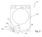
- the household appliance 101 comprises an external casing 102, substantially parallelepiped in shaped and preferably made of sheet metal, with a bottom 103, approximately flat, which plan is opportunely square or rectangular.
- the bottom 103 may include one or more brackets, not shown in the attached Figures, preferably metallic and preferably with an approximately rectangular plan, mounted below a metal box, also not shown, typically rectangular and hollow, which forms the body of the external casing 102.
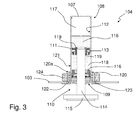
- the self-levelling support foot 104 advantageously includes a hollow tubular body 107, closed at a first end 108 thereof and open at its second end 109, positioned, in use, at least partially within the external casing 102, and fixed to the bottom 103 thereof proximate to the second end 109.
- tubular body 107 is fixed to the bottom 103 by suitable fixing means, which will be described in the following.
- a piston 110 provided with a head 111 slidably associated with the inner lateral surface 112 of the tubular body 107; opportunely, the head 111 is provided with a ring-shaped gasket 113, preferably of the O-ring type, inserted in a groove formed in the lateral surface of the head 111 and protruding radially from such ring-shaped groove so as to abut the inner lateral surface 112, realizing the sealing therewith.
- a stem 114 projects from the head 111, the stem 114 protruding at least partially from the second end 109 of the tubular body 107, so as to protrude outside the bottom 103 of the external casing 102 of the household appliance 101.
- a foot 115 preferably cylindrical or prismatic and made of plastic, able to rest, in use, on the floor 105.
- sealing means adapted to prevent the leakage of liquid and/or gas from the tubular body 107;
- sealing means comprise, for example, one or more gaskets and/or sealing rings and/or thrust bearings, indicated as a whole with the number 116, associated with the second end 109 of the tubular body 107 and configured so as to allow the sliding therethrough of the stem 114, while blocking the passage of liquid and/or gas.
- a gas indicated by the number 117, with pressure above the atmospheric pressure;
- the gas 117 can advantageously be, for example, nitrogen.
- the effect of the gas 117 is to establish within the tubular body 107 a pressure higher than the atmospheric pressure, thus generating a force on the piston 110 that tends to push it out of the tubular body 107.
- a liquid numbered 118 in Figure 3 , which may be, for example, mineral oil.
- the effect of the liquid 118 is to reduce the acceleration of the piston 110 within the tubular body 107, so as to dampen any sudden stresses that may affect the household appliance 101.
- the positioning of gas 117 and liquid 118 within the tubular body 107 is such that the head 111 of the piston 110 is constantly immersed in the liquid 118.
- the head 111 there are leakage means adapted to allow the head 111 to be passed through by the liquid 118 during the translation of the head 111, with a simultaneous dampening effect on the motion of the head 111 within the tubular element 107, as will be explained in the following.
- leakage means include one or more channels 119 obtained in the head 111 in order to realize a fluid connection between the surface of the head 111 which is oriented towards the first end 108 of the tubular body 107 with the surface of the head 111 which is oriented towards the second end 109 of the tubular body 107.
- these leakage means may include one or more through openings, obtained in the ring-shaped gasket 113, adapted to enable the leakage of fluid 118.
- the seal ring 113 is not present, and the leakage means advantageously comprise a narrow gap defined between the outer lateral surface of the head 111 and the inner lateral surface 112 of the tubular body 107, through which the liquid 118 can leak out.
- the pressure of the gas 107 and of the liquid 118 is the same; since the area of the surface of the head 111 which is oriented towards the first end 108 of the tubular body 107 (which is essentially circular) is wider than the area of the surface of the head 111 which is oriented towards the second end 109 of the tubular body 107 (which is basically an annulus, due to the presence of the stem 114), and since both these surfaces are in contact with the liquid 118, a force acts on the head 111 (substantially equal to the product of the fluid pressure by the difference between the two areas mentioned above) which tends to constantly push the piston 110 towards the outside of the tubular body 107.
- the pressure of the gas 117 is determined, preferably during the production phase, so that the force acting on the piston 110 and directed outwards the tubular body 107 is approximately equal to the fraction of the weight of the household appliance 101 that, in use, acts on the self-levelling support foot 104; in the embodiment shown in the attached figures, where there are four feet one of which is self-levelling, the pressure of the gas 117 is then preferably fixed such that the force acting on the piston 110 and directed outwards the tubular body 107 is equal to about one quarter of the household appliance's weight 101.
- the liquid 118 may pass beyond the head 111 through the leakage means and thus, in the embodiment illustrated in Figures 2 and 3 , through the channels 119; because of their small size, these channels 119 allow the passage of a small quantity of liquid 117 per unit time, thus limiting the acceleration of the piston 110.
- the resulting effect is a damping of the stresses that tend to cause sudden mutual displacements between the piston 110 and the tubular body 107.
- said fixing means adapted to fix the tubular body 107 to the bottom 103 of the casing 102 of the household appliance 101 advantageously comprise an externally threaded ferrule 120 fixed coaxially to the external surface 121 of the tubular body 107, for example by gluing, near its second end 109.
- ring-shaped appendix 122 radially projects, the appendix 122 being arranged so that at least a section 120a of the threaded outer lateral surface of the ferrule 120 is positioned between said ring-shaped appendix 122 and the first end 108 of the tubular body 107.
- the ferrule 120 is positioned, in use, within a hole 123 formed at the bottom 103 of the casing 102 of the household appliance 101, so that the ring-shaped appendix 122 abuts the external surface of the bottom 103, and the section 120a of the external lateral surface of the ferrule 120 is positioned at least partially within the external casing 102.
- Such fixing means also include a nut 124 which can be screwed onto the section 120a of the threaded external lateral surface of the ferrule 120 so as to clamp tight the bottom 103 between the nut 124 and the ring-shaped appendix 122.
- the fixing of the self-levelling support foot 104 according to the invention to the bottom 103 of the household appliance 101 involves only two phases (insertion of the tubular body 107 into the external casing 102 and fastening of the nut 124 to the ferrule 120), compared to the three steps necessary to the mounting to the bottom of the household appliance of the self-levelling support foot of known type shown and described with reference to the attached Figure 1 ; the fastening of the self-levelling support foot 104 according to the invention to the bottom 103 of the household appliance 101 is thus faster than the prior art cited above, resulting in lower production costs of the household appliance 101.
- said fixing means may comprise, for example, a weld or an adhesive, applied at the interface between the tubular body 107 and the bottom 103, so as to firmly connect them.
- the pre-adjustment of the height of the three adjustable feet 106 may be performed manually prior to the placement in operation of the household appliances 101, so as to define a desired support surface on the floor 105 passing through the abutment points of these three feet 106; once the household appliance 101 is placed on the floor 105, the three manually adjustable feet 106 come into contact with the floor 105, according to the preset support plane defined by them.
- the stem 114 of the piston 110 of the self-levelling support foot 104 is kept pressed toward the outside of the tubular body 107, so that the foot 115 at the free end of the stem 114 abuts the floor 105 even if the support point of such foot 115 falls outside the support plane defined by the three manually adjustable feet 105, thereby ensuring the stability of the support of the household appliance 101.
- the invention has achieved the proposed aim and objects, having provided a household appliance which, thanks to the presence of at least one self-levelling support foot according to the invention, maintains a safe and stable standing on the ground even in case of irregularities in the conformation of the floor on which it is leaned, and even in presence of sudden mechanical stresses applied to the household appliance, while keeping the production costs reduced.
- the fixing of the self-levelling support foot according the invention to the bottom of a household appliance is easy and quick, thereby reducing the production costs of the household appliance compared to the mentioned prior art solutions.
- the self-levelling support foot thanks to the presence of the liquid that surrounds the head of the piston and the leakage means, can very effectively dampen any sudden stress to which the household appliance can be exposed.
Landscapes
- Engineering & Computer Science (AREA)
- Textile Engineering (AREA)
- Fluid-Damping Devices (AREA)
- Chairs Characterized By Structure (AREA)
Priority Applications (1)
| Application Number | Priority Date | Filing Date | Title |
|---|---|---|---|
| EP09179191A EP2336416B1 (fr) | 2009-12-15 | 2009-12-15 | Appareil domestique avec stabilité de support améliorée |
Applications Claiming Priority (1)
| Application Number | Priority Date | Filing Date | Title |
|---|---|---|---|
| EP09179191A EP2336416B1 (fr) | 2009-12-15 | 2009-12-15 | Appareil domestique avec stabilité de support améliorée |
Publications (2)
| Publication Number | Publication Date |
|---|---|
| EP2336416A1 true EP2336416A1 (fr) | 2011-06-22 |
| EP2336416B1 EP2336416B1 (fr) | 2013-02-20 |
Family
ID=42115462
Family Applications (1)
| Application Number | Title | Priority Date | Filing Date |
|---|---|---|---|
| EP09179191A Not-in-force EP2336416B1 (fr) | 2009-12-15 | 2009-12-15 | Appareil domestique avec stabilité de support améliorée |
Country Status (1)
| Country | Link |
|---|---|
| EP (1) | EP2336416B1 (fr) |
Cited By (5)
| Publication number | Priority date | Publication date | Assignee | Title |
|---|---|---|---|---|
| CN105757408A (zh) * | 2016-04-13 | 2016-07-13 | 青岛海尔洗衣机有限公司 | 一种家用电器及其调平装置 |
| CN105755750A (zh) * | 2016-04-13 | 2016-07-13 | 青岛海尔洗衣机有限公司 | 具有自动调平功能的洗衣机底脚及洗衣机 |
| WO2018001317A1 (fr) * | 2016-06-30 | 2018-01-04 | 青岛海尔洗衣机有限公司 | Machine à laver à mise à niveau automatique |
| CN107588290A (zh) * | 2016-07-08 | 2018-01-16 | 青岛海尔洗衣机有限公司 | 一种家用电器的调平装置及具有该装置的家用电器 |
| CN108278449A (zh) * | 2017-01-06 | 2018-07-13 | 青岛海尔洗衣机有限公司 | 一种家用电器用底脚及家用电器 |
Citations (7)
| Publication number | Priority date | Publication date | Assignee | Title |
|---|---|---|---|---|
| US2775849A (en) * | 1953-07-16 | 1957-01-01 | Frank W Ingram | Furniture stabilizing device |
| US2823915A (en) * | 1953-05-21 | 1958-02-18 | Bourcier Christian Marie Louis | Shock absorbers |
| US2823975A (en) * | 1954-04-05 | 1958-02-18 | Apex Electrical Mfg Co | Washing machine |
| FR1365427A (fr) * | 1963-05-20 | 1964-07-03 | Dispositif de réglage en hauteur, notamment pour sièges | |
| US3144234A (en) * | 1961-09-08 | 1964-08-11 | Artmann Kurt | Support structure for furniture and the like |
| US3191895A (en) * | 1963-03-06 | 1965-06-29 | Gen Motors Corp | Platform stabilizer |
| US3550405A (en) * | 1968-11-26 | 1970-12-29 | Gen Electric | Positive fill control and weight distribution system for an automatic washer |
-
2009
- 2009-12-15 EP EP09179191A patent/EP2336416B1/fr not_active Not-in-force
Patent Citations (7)
| Publication number | Priority date | Publication date | Assignee | Title |
|---|---|---|---|---|
| US2823915A (en) * | 1953-05-21 | 1958-02-18 | Bourcier Christian Marie Louis | Shock absorbers |
| US2775849A (en) * | 1953-07-16 | 1957-01-01 | Frank W Ingram | Furniture stabilizing device |
| US2823975A (en) * | 1954-04-05 | 1958-02-18 | Apex Electrical Mfg Co | Washing machine |
| US3144234A (en) * | 1961-09-08 | 1964-08-11 | Artmann Kurt | Support structure for furniture and the like |
| US3191895A (en) * | 1963-03-06 | 1965-06-29 | Gen Motors Corp | Platform stabilizer |
| FR1365427A (fr) * | 1963-05-20 | 1964-07-03 | Dispositif de réglage en hauteur, notamment pour sièges | |
| US3550405A (en) * | 1968-11-26 | 1970-12-29 | Gen Electric | Positive fill control and weight distribution system for an automatic washer |
Cited By (11)
| Publication number | Priority date | Publication date | Assignee | Title |
|---|---|---|---|---|
| CN105757408A (zh) * | 2016-04-13 | 2016-07-13 | 青岛海尔洗衣机有限公司 | 一种家用电器及其调平装置 |
| CN105755750A (zh) * | 2016-04-13 | 2016-07-13 | 青岛海尔洗衣机有限公司 | 具有自动调平功能的洗衣机底脚及洗衣机 |
| JP2019511324A (ja) * | 2016-04-13 | 2019-04-25 | 青島海爾洗衣机有限公司QingDao Haier Washing Machine Co.,Ltd. | 家電製品のレベリング装置および該装置を有する家電製品 |
| CN105757408B (zh) * | 2016-04-13 | 2024-02-20 | 青岛海尔洗衣机有限公司 | 一种家用电器及其调平装置 |
| CN105755750B (zh) * | 2016-04-13 | 2024-04-02 | 青岛海尔洗衣机有限公司 | 具有自动调平功能的洗衣机底脚及洗衣机 |
| WO2018001317A1 (fr) * | 2016-06-30 | 2018-01-04 | 青岛海尔洗衣机有限公司 | Machine à laver à mise à niveau automatique |
| CN107588290A (zh) * | 2016-07-08 | 2018-01-16 | 青岛海尔洗衣机有限公司 | 一种家用电器的调平装置及具有该装置的家用电器 |
| CN107588290B (zh) * | 2016-07-08 | 2020-05-22 | 青岛海尔洗衣机有限公司 | 一种家用电器 |
| CN108278449A (zh) * | 2017-01-06 | 2018-07-13 | 青岛海尔洗衣机有限公司 | 一种家用电器用底脚及家用电器 |
| EP3567297A4 (fr) * | 2017-01-06 | 2019-11-13 | Qingdao Haier Washing Machine Co., Ltd. | Pied pour appareil électroménager et appareil électroménager |
| CN108278449B (zh) * | 2017-01-06 | 2021-01-26 | 青岛海尔洗衣机有限公司 | 一种家用电器用底脚及家用电器 |
Also Published As
| Publication number | Publication date |
|---|---|
| EP2336416B1 (fr) | 2013-02-20 |
Similar Documents
| Publication | Publication Date | Title |
|---|---|---|
| EP3444395B1 (fr) | Pied de machine à laver ayant une fonction de mise à niveau automatique, et machine à laver | |
| EP2336416B1 (fr) | Appareil domestique avec stabilité de support améliorée | |
| EP3502339B1 (fr) | Une machine à laver comprenant un pied de machine à laver avec une fonction de nivellement automatique | |
| KR101239311B1 (ko) | 수평유지 조립체 | |
| US10221517B2 (en) | Foot of a washing machine with automatic leveling function and a washing machine thereof | |
| US10626541B2 (en) | Hydraulic leveling device of washing machine and filling method thereof | |
| JP6889240B2 (ja) | 家電製品 | |
| US10920360B2 (en) | Support for washing machine with automatic leveling function and washing machine | |
| US20180245266A1 (en) | Hydraulic leveling base and washing machine | |
| US10704188B2 (en) | Automatic leveling washing machine | |
| JP2019524316A (ja) | 自動レベリング機能を有する洗濯機の底脚及び洗濯機 | |
| US11124914B2 (en) | Support leveling device for a household appliance, and a household appliance | |
| WO2017122566A1 (fr) | Dispositif de prévention de basculement | |
| JP7142084B2 (ja) | 家電製品用支持レベリング装置及び家電製品 | |
| ITMI20082270A1 (it) | Elettrodomestico a stabilità di appoggio migliorata | |
| JP6333311B2 (ja) | ブラケット、及び転倒防止装置 | |
| KR100739154B1 (ko) | 세탁기의 지지장치 및 자체높이조절기능을 가지는 지지장치 | |
| JP2020512094A (ja) | 家電製品用底脚及び家電製品 | |
| KR101058693B1 (ko) | 세탁기의 자동 높이 조절 장치 | |
| PL187531B1 (pl) | Wibroizolator |
Legal Events
| Date | Code | Title | Description |
|---|---|---|---|
| PUAI | Public reference made under article 153(3) epc to a published international application that has entered the european phase |
Free format text: ORIGINAL CODE: 0009012 |
|
| AK | Designated contracting states |
Kind code of ref document: A1 Designated state(s): AT BE BG CH CY CZ DE DK EE ES FI FR GB GR HR HU IE IS IT LI LT LU LV MC MK MT NL NO PL PT RO SE SI SK SM TR |
|
| AX | Request for extension of the european patent |
Extension state: AL BA RS |
|
| RAP1 | Party data changed (applicant data changed or rights of an application transferred) |
Owner name: ELECTROLUX HOME PRODUCTS CORPORATION N.V. |
|
| 17P | Request for examination filed |
Effective date: 20111222 |
|
| GRAP | Despatch of communication of intention to grant a patent |
Free format text: ORIGINAL CODE: EPIDOSNIGR1 |
|
| GRAS | Grant fee paid |
Free format text: ORIGINAL CODE: EPIDOSNIGR3 |
|
| GRAA | (expected) grant |
Free format text: ORIGINAL CODE: 0009210 |
|
| AK | Designated contracting states |
Kind code of ref document: B1 Designated state(s): AT BE BG CH CY CZ DE DK EE ES FI FR GB GR HR HU IE IS IT LI LT LU LV MC MK MT NL NO PL PT RO SE SI SK SM TR |
|
| REG | Reference to a national code |
Ref country code: GB Ref legal event code: FG4D |
|
| REG | Reference to a national code |
Ref country code: CH Ref legal event code: EP |
|
| REG | Reference to a national code |
Ref country code: AT Ref legal event code: REF Ref document number: 597624 Country of ref document: AT Kind code of ref document: T Effective date: 20130315 |
|
| REG | Reference to a national code |
Ref country code: IE Ref legal event code: FG4D |
|
| REG | Reference to a national code |
Ref country code: DE Ref legal event code: R096 Ref document number: 602009013413 Country of ref document: DE Effective date: 20130418 |
|
| REG | Reference to a national code |
Ref country code: AT Ref legal event code: MK05 Ref document number: 597624 Country of ref document: AT Kind code of ref document: T Effective date: 20130220 |
|
| REG | Reference to a national code |
Ref country code: NL Ref legal event code: VDEP Effective date: 20130220 |
|
| REG | Reference to a national code |
Ref country code: LT Ref legal event code: MG4D |
|
| PG25 | Lapsed in a contracting state [announced via postgrant information from national office to epo] |
Ref country code: IS Free format text: LAPSE BECAUSE OF FAILURE TO SUBMIT A TRANSLATION OF THE DESCRIPTION OR TO PAY THE FEE WITHIN THE PRESCRIBED TIME-LIMIT Effective date: 20130620 Ref country code: LT Free format text: LAPSE BECAUSE OF FAILURE TO SUBMIT A TRANSLATION OF THE DESCRIPTION OR TO PAY THE FEE WITHIN THE PRESCRIBED TIME-LIMIT Effective date: 20130220 Ref country code: AT Free format text: LAPSE BECAUSE OF FAILURE TO SUBMIT A TRANSLATION OF THE DESCRIPTION OR TO PAY THE FEE WITHIN THE PRESCRIBED TIME-LIMIT Effective date: 20130220 Ref country code: ES Free format text: LAPSE BECAUSE OF FAILURE TO SUBMIT A TRANSLATION OF THE DESCRIPTION OR TO PAY THE FEE WITHIN THE PRESCRIBED TIME-LIMIT Effective date: 20130531 Ref country code: BG Free format text: LAPSE BECAUSE OF FAILURE TO SUBMIT A TRANSLATION OF THE DESCRIPTION OR TO PAY THE FEE WITHIN THE PRESCRIBED TIME-LIMIT Effective date: 20130520 Ref country code: NO Free format text: LAPSE BECAUSE OF FAILURE TO SUBMIT A TRANSLATION OF THE DESCRIPTION OR TO PAY THE FEE WITHIN THE PRESCRIBED TIME-LIMIT Effective date: 20130520 Ref country code: SE Free format text: LAPSE BECAUSE OF FAILURE TO SUBMIT A TRANSLATION OF THE DESCRIPTION OR TO PAY THE FEE WITHIN THE PRESCRIBED TIME-LIMIT Effective date: 20130220 |
|
| PG25 | Lapsed in a contracting state [announced via postgrant information from national office to epo] |
Ref country code: PL Free format text: LAPSE BECAUSE OF FAILURE TO SUBMIT A TRANSLATION OF THE DESCRIPTION OR TO PAY THE FEE WITHIN THE PRESCRIBED TIME-LIMIT Effective date: 20130220 Ref country code: SI Free format text: LAPSE BECAUSE OF FAILURE TO SUBMIT A TRANSLATION OF THE DESCRIPTION OR TO PAY THE FEE WITHIN THE PRESCRIBED TIME-LIMIT Effective date: 20130220 Ref country code: LV Free format text: LAPSE BECAUSE OF FAILURE TO SUBMIT A TRANSLATION OF THE DESCRIPTION OR TO PAY THE FEE WITHIN THE PRESCRIBED TIME-LIMIT Effective date: 20130220 Ref country code: FI Free format text: LAPSE BECAUSE OF FAILURE TO SUBMIT A TRANSLATION OF THE DESCRIPTION OR TO PAY THE FEE WITHIN THE PRESCRIBED TIME-LIMIT Effective date: 20130220 Ref country code: BE Free format text: LAPSE BECAUSE OF FAILURE TO SUBMIT A TRANSLATION OF THE DESCRIPTION OR TO PAY THE FEE WITHIN THE PRESCRIBED TIME-LIMIT Effective date: 20130220 Ref country code: PT Free format text: LAPSE BECAUSE OF FAILURE TO SUBMIT A TRANSLATION OF THE DESCRIPTION OR TO PAY THE FEE WITHIN THE PRESCRIBED TIME-LIMIT Effective date: 20130620 Ref country code: GR Free format text: LAPSE BECAUSE OF FAILURE TO SUBMIT A TRANSLATION OF THE DESCRIPTION OR TO PAY THE FEE WITHIN THE PRESCRIBED TIME-LIMIT Effective date: 20130521 |
|
| PG25 | Lapsed in a contracting state [announced via postgrant information from national office to epo] |
Ref country code: HR Free format text: LAPSE BECAUSE OF FAILURE TO SUBMIT A TRANSLATION OF THE DESCRIPTION OR TO PAY THE FEE WITHIN THE PRESCRIBED TIME-LIMIT Effective date: 20130220 |
|
| PG25 | Lapsed in a contracting state [announced via postgrant information from national office to epo] |
Ref country code: NL Free format text: LAPSE BECAUSE OF FAILURE TO SUBMIT A TRANSLATION OF THE DESCRIPTION OR TO PAY THE FEE WITHIN THE PRESCRIBED TIME-LIMIT Effective date: 20130220 Ref country code: SK Free format text: LAPSE BECAUSE OF FAILURE TO SUBMIT A TRANSLATION OF THE DESCRIPTION OR TO PAY THE FEE WITHIN THE PRESCRIBED TIME-LIMIT Effective date: 20130220 Ref country code: CZ Free format text: LAPSE BECAUSE OF FAILURE TO SUBMIT A TRANSLATION OF THE DESCRIPTION OR TO PAY THE FEE WITHIN THE PRESCRIBED TIME-LIMIT Effective date: 20130220 Ref country code: RO Free format text: LAPSE BECAUSE OF FAILURE TO SUBMIT A TRANSLATION OF THE DESCRIPTION OR TO PAY THE FEE WITHIN THE PRESCRIBED TIME-LIMIT Effective date: 20130220 Ref country code: DK Free format text: LAPSE BECAUSE OF FAILURE TO SUBMIT A TRANSLATION OF THE DESCRIPTION OR TO PAY THE FEE WITHIN THE PRESCRIBED TIME-LIMIT Effective date: 20130220 Ref country code: EE Free format text: LAPSE BECAUSE OF FAILURE TO SUBMIT A TRANSLATION OF THE DESCRIPTION OR TO PAY THE FEE WITHIN THE PRESCRIBED TIME-LIMIT Effective date: 20130220 |
|
| PLBE | No opposition filed within time limit |
Free format text: ORIGINAL CODE: 0009261 |
|
| STAA | Information on the status of an ep patent application or granted ep patent |
Free format text: STATUS: NO OPPOSITION FILED WITHIN TIME LIMIT |
|
| PG25 | Lapsed in a contracting state [announced via postgrant information from national office to epo] |
Ref country code: IT Free format text: LAPSE BECAUSE OF FAILURE TO SUBMIT A TRANSLATION OF THE DESCRIPTION OR TO PAY THE FEE WITHIN THE PRESCRIBED TIME-LIMIT Effective date: 20130220 |
|
| 26N | No opposition filed |
Effective date: 20131121 |
|
| PGFP | Annual fee paid to national office [announced via postgrant information from national office to epo] |
Ref country code: GB Payment date: 20131219 Year of fee payment: 5 |
|
| REG | Reference to a national code |
Ref country code: DE Ref legal event code: R097 Ref document number: 602009013413 Country of ref document: DE Effective date: 20131121 |
|
| PGFP | Annual fee paid to national office [announced via postgrant information from national office to epo] |
Ref country code: FR Payment date: 20131220 Year of fee payment: 5 |
|
| REG | Reference to a national code |
Ref country code: CH Ref legal event code: PL |
|
| PG25 | Lapsed in a contracting state [announced via postgrant information from national office to epo] |
Ref country code: MC Free format text: LAPSE BECAUSE OF FAILURE TO SUBMIT A TRANSLATION OF THE DESCRIPTION OR TO PAY THE FEE WITHIN THE PRESCRIBED TIME-LIMIT Effective date: 20130220 Ref country code: LU Free format text: LAPSE BECAUSE OF FAILURE TO SUBMIT A TRANSLATION OF THE DESCRIPTION OR TO PAY THE FEE WITHIN THE PRESCRIBED TIME-LIMIT Effective date: 20131215 |
|
| PGFP | Annual fee paid to national office [announced via postgrant information from national office to epo] |
Ref country code: DE Payment date: 20131220 Year of fee payment: 5 |
|
| REG | Reference to a national code |
Ref country code: IE Ref legal event code: MM4A |
|
| PG25 | Lapsed in a contracting state [announced via postgrant information from national office to epo] |
Ref country code: IE Free format text: LAPSE BECAUSE OF NON-PAYMENT OF DUE FEES Effective date: 20131215 Ref country code: LI Free format text: LAPSE BECAUSE OF NON-PAYMENT OF DUE FEES Effective date: 20131231 Ref country code: CH Free format text: LAPSE BECAUSE OF NON-PAYMENT OF DUE FEES Effective date: 20131231 |
|
| PG25 | Lapsed in a contracting state [announced via postgrant information from national office to epo] |
Ref country code: SM Free format text: LAPSE BECAUSE OF FAILURE TO SUBMIT A TRANSLATION OF THE DESCRIPTION OR TO PAY THE FEE WITHIN THE PRESCRIBED TIME-LIMIT Effective date: 20130220 |
|
| PG25 | Lapsed in a contracting state [announced via postgrant information from national office to epo] |
Ref country code: TR Free format text: LAPSE BECAUSE OF FAILURE TO SUBMIT A TRANSLATION OF THE DESCRIPTION OR TO PAY THE FEE WITHIN THE PRESCRIBED TIME-LIMIT Effective date: 20130220 Ref country code: CY Free format text: LAPSE BECAUSE OF FAILURE TO SUBMIT A TRANSLATION OF THE DESCRIPTION OR TO PAY THE FEE WITHIN THE PRESCRIBED TIME-LIMIT Effective date: 20130220 |
|
| REG | Reference to a national code |
Ref country code: DE Ref legal event code: R119 Ref document number: 602009013413 Country of ref document: DE |
|
| PG25 | Lapsed in a contracting state [announced via postgrant information from national office to epo] |
Ref country code: HU Free format text: LAPSE BECAUSE OF FAILURE TO SUBMIT A TRANSLATION OF THE DESCRIPTION OR TO PAY THE FEE WITHIN THE PRESCRIBED TIME-LIMIT; INVALID AB INITIO Effective date: 20091215 Ref country code: MK Free format text: LAPSE BECAUSE OF FAILURE TO SUBMIT A TRANSLATION OF THE DESCRIPTION OR TO PAY THE FEE WITHIN THE PRESCRIBED TIME-LIMIT Effective date: 20130220 |
|
| GBPC | Gb: european patent ceased through non-payment of renewal fee |
Effective date: 20141215 |
|
| PG25 | Lapsed in a contracting state [announced via postgrant information from national office to epo] |
Ref country code: MT Free format text: LAPSE BECAUSE OF FAILURE TO SUBMIT A TRANSLATION OF THE DESCRIPTION OR TO PAY THE FEE WITHIN THE PRESCRIBED TIME-LIMIT Effective date: 20130220 |
|
| REG | Reference to a national code |
Ref country code: FR Ref legal event code: ST Effective date: 20150831 |
|
| PG25 | Lapsed in a contracting state [announced via postgrant information from national office to epo] |
Ref country code: GB Free format text: LAPSE BECAUSE OF NON-PAYMENT OF DUE FEES Effective date: 20141215 Ref country code: DE Free format text: LAPSE BECAUSE OF NON-PAYMENT OF DUE FEES Effective date: 20150701 |
|
| PG25 | Lapsed in a contracting state [announced via postgrant information from national office to epo] |
Ref country code: FR Free format text: LAPSE BECAUSE OF NON-PAYMENT OF DUE FEES Effective date: 20141231 |