EP2336450A2 - Store et l'utilisation d'un store - Google Patents
Store et l'utilisation d'un store Download PDFInfo
- Publication number
- EP2336450A2 EP2336450A2 EP20100192107 EP10192107A EP2336450A2 EP 2336450 A2 EP2336450 A2 EP 2336450A2 EP 20100192107 EP20100192107 EP 20100192107 EP 10192107 A EP10192107 A EP 10192107A EP 2336450 A2 EP2336450 A2 EP 2336450A2
- Authority
- EP
- European Patent Office
- Prior art keywords
- sun
- blocking part
- supporting part
- protection device
- sun blocking
- Prior art date
- Legal status (The legal status is an assumption and is not a legal conclusion. Google has not performed a legal analysis and makes no representation as to the accuracy of the status listed.)
- Granted
Links
Images





Classifications
-
- E—FIXED CONSTRUCTIONS
- E04—BUILDING
- E04F—FINISHING WORK ON BUILDINGS, e.g. STAIRS, FLOORS
- E04F10/00—Sunshades, e.g. Florentine blinds or jalousies; Outside screens; Awnings or baldachins
- E04F10/02—Sunshades, e.g. Florentine blinds or jalousies; Outside screens; Awnings or baldachins of flexible canopy materials, e.g. canvas ; Baldachins
- E04F10/06—Sunshades, e.g. Florentine blinds or jalousies; Outside screens; Awnings or baldachins of flexible canopy materials, e.g. canvas ; Baldachins comprising a roller-blind with means for holding the end away from a building
- E04F10/0666—Accessories
- E04F10/0681—Support posts for the movable end of the blind
-
- E—FIXED CONSTRUCTIONS
- E04—BUILDING
- E04F—FINISHING WORK ON BUILDINGS, e.g. STAIRS, FLOORS
- E04F10/00—Sunshades, e.g. Florentine blinds or jalousies; Outside screens; Awnings or baldachins
- E04F10/02—Sunshades, e.g. Florentine blinds or jalousies; Outside screens; Awnings or baldachins of flexible canopy materials, e.g. canvas ; Baldachins
- E04F10/06—Sunshades, e.g. Florentine blinds or jalousies; Outside screens; Awnings or baldachins of flexible canopy materials, e.g. canvas ; Baldachins comprising a roller-blind with means for holding the end away from a building
- E04F10/0607—Sunshades, e.g. Florentine blinds or jalousies; Outside screens; Awnings or baldachins of flexible canopy materials, e.g. canvas ; Baldachins comprising a roller-blind with means for holding the end away from a building with guiding-sections for supporting the movable end of the blind
-
- E—FIXED CONSTRUCTIONS
- E04—BUILDING
- E04F—FINISHING WORK ON BUILDINGS, e.g. STAIRS, FLOORS
- E04F10/00—Sunshades, e.g. Florentine blinds or jalousies; Outside screens; Awnings or baldachins
- E04F10/02—Sunshades, e.g. Florentine blinds or jalousies; Outside screens; Awnings or baldachins of flexible canopy materials, e.g. canvas ; Baldachins
- E04F10/06—Sunshades, e.g. Florentine blinds or jalousies; Outside screens; Awnings or baldachins of flexible canopy materials, e.g. canvas ; Baldachins comprising a roller-blind with means for holding the end away from a building
- E04F10/0637—Sunshades, e.g. Florentine blinds or jalousies; Outside screens; Awnings or baldachins of flexible canopy materials, e.g. canvas ; Baldachins comprising a roller-blind with means for holding the end away from a building with mechanisms for adjusting the inclination of the blind
-
- E—FIXED CONSTRUCTIONS
- E06—DOORS, WINDOWS, SHUTTERS, OR ROLLER BLINDS IN GENERAL; LADDERS
- E06B—FIXED OR MOVABLE CLOSURES FOR OPENINGS IN BUILDINGS, VEHICLES, FENCES OR LIKE ENCLOSURES IN GENERAL, e.g. DOORS, WINDOWS, BLINDS, GATES
- E06B9/00—Screening or protective devices for wall or similar openings, with or without operating or securing mechanisms; Closures of similar construction
- E06B9/56—Operating, guiding or securing devices or arrangements for roll-type closures; Spring drums; Tape drums; Counterweighting arrangements therefor
- E06B9/92—Means allowing the closures to be shifted out of the plane of the opening
Definitions
- the invention relates to a sun protection device provided with a sun blocking part and a supporting part for supporting the sun blocking part, wherein the sun blocking part preferably comprises a screen that can be slid in and slid out.
- sun protection devices for verandas are provided with a supporting part and a sun blocking part.
- the sun blocking part usually comprises a screen that is intended to offer protection against the sun.
- Such sun protection devices may be constructed with a screen that can be slid in and slid out along side guides. By sliding the screen in and out, known sun protection devices can to a certain extent be adjusted to weather conditions. When the sun disappears behind the clouds, the screen can, for example, be slid away, and when the sun comes back, the screen can be slid back. Sun protection devices with a screen that cannot be slid in and out lack this adjustment possibility.
- the known sun protection device will offer optimum protection against the sun only during a part of the day. The fact is, even with a wholly slid-out screen, it can easily happen that the known screen does not offer adequate protection against a low sun. This can be quite a nuisance to a user who, under the screen, finds the low sun annoyingly shining on him.
- the invention provides a sun protection device, provided with a sun blocking part and a supporting part for supporting the sun blocking part, wherein the sun blocking part preferably comprises a screen that can be slid in and slid out, wherein the supporting part comprises at least a first support element and a second support element which are immovably connected with each other and extend in mutually different directions along the sun blocking part, wherein the sun blocking part is tiltably connected to the supporting part according to a tilting axis, which extends between two mutually spaced apart points of which a first point is associated with the first support element and a second point is associated with the second support element.
- the sun blocking part can be tilted with respect to the supporting part, it can be adjusted to the position of the sun.
- the sun protection device offers protection from the sun during a relatively large part of a sunny day, without the dimensions of the sun protection device needing to be enlarged for this purpose.
- the two mutually spaced apart points are preferably chosen for reducing, and preferably minimizing, a moment that the weight of the sun blocking part exerts on attachments of the sun blocking part to the supporting part.
- Directions that are not in line with each other in a straight line can be regarded as mutually different directions.
- the sun protection device additionally offers a surprising advantage.
- unwanted material such as rainwater or leaves
- tilting the sun blocking part unwanted material, such as rainwater or leaves, can be removed from the sun protection device.
- Such removal can occur in that the unwanted material of itself falls off the sun blocking part.
- the unwanted material may be better accessible, so that it can be removed, for example, using a broom, garden hose and/or high pressure cleaner.
- the sun blocking part comprises a screen that can be slid in, and for example pulled in, and can be slid out, and for example pulled out.
- the sun protection device is considered to be particularly advantageous.
- many sliding screens are sensitive to the unwanted material that may be left on the screen.
- water may be entrained, causing the screen to remain wet for a long time.
- the quality of the screen may deteriorate rapidly.
- the unwanted material may soil means for sliding the screen in and out. This may compromise the proper functioning of these means, such as windup means and side guides for the screen.
- the first point coincides with the first support element and a second point coincides with the second support element. It will be clear that in this manner the first point is associated with the first support element and a second point is associated with the second support element.
- the first point may be located in line with the first support element, preferably near the first support element.
- the second point may be located in line with the second support element, preferably near the second support element.
- the sun blocking part is situated at least partly between the two mutually spaced apart points.
- a moment that the weight of the sun blocking part exerts on the attachments of the sun blocking part to the supporting part will be reduced.
- the mutually different directions in which the first and second support element extend are directed transversely to each other. In another embodiment, the mutually different directions in which the first and second support element extend are directed substantially parallel to each other. Optionally, the mutually different directions in which the first and second support element extend are directed obliquely to each other.
- the first support element and the second support element are formed by substantially horizontally extending girders.
- Such substantially horizontally extending girders in use, make, for example, an angle of at most 30 degrees with the horizontal. With such substantially horizontally extending girders, a sturdy support of the sun blocking part can be achieved.
- the first support element and the second support element are included in a framework formed by the supporting part, which framework, preferably wholly, surrounds the sun blocking part.
- a framework results in a construction of great sturdiness.
- “Wholly surrounding” is involved when the framework forms an all-round closed periphery around the sun blocking part.
- “Surrounding” is already involved when the framework surrounds the sun blocking part in part, though for a substantial part.
- the framework then forms, for example, a minimum of 80 percent of the fully closed periphery around the sun blocking part.
- the framework can comprise, for example, four, such as just four, substantially horizontal girders.
- the framework, and preferably the four girders can extend, for example, in one plane.
- the framework and preferably the four girders, can form, for example, a rectangle, a trapezium or a parallelogram.
- the framework can form a triangle.
- the plane in which the framework, and preferably the four girders, extends, is, for example, with the sun blocking part in untilted situation, (approximately) parallel to a plane in which the sun blocking part extends.
- the framework comprises a tubular section of preferably rectangular cross section.
- the tubular section can form an inner surface of the framework, which inner surface faces the sun blocking part.
- the first and the second point, between which the tilting axis extends, can then be located, for example, on the inner surface of the tubular section.
- the sun blocking part has at least two ends by which it is tiltably connected to the supporting part at the two mutually spaced apart points.
- the at least two ends are formed by corners of the sun blocking part.
- the ends can be formed, for example, by opposite corners of the sun blocking part, for example, when the sun blocking part has at least four corners.
- the at least two ends are formed by adjacent corners. Between adjacent corners no other corner is located. In this manner, during tilting, the sun blocking part will move practically wholly in the same direction, for example, upwards or downwards. This makes tilting straightforward, which can prevent accidents.
- the at least two ends are formed by different longitudinal edges of the sun blocking part.
- the at least two ends are opposite longitudinal edges. Opposite longitudinal edges are involved when the shortest path between the longitudinal edges crosses the, preferably wholly slid-out, screen. The screen is then between the opposite longitudinal edges.
- the sun protection device is adapted for, at will of the user, tilting the sun blocking part in one of at least two different directions.
- tilting the sun blocking part in one of at least two different directions.
- the sun blocking part is tiltable in a plane that is directed transversely to a plane in which the sun blocking part extends.
- an orientation of the sun blocking part can be effectively adjusted to the position of the sun.
- the fact is, in this manner it is possible to change an angle of the plane in which the sun blocking part extends with respect to the sun, while the supporting part is at rest.
- the sun blocking part may, for example, in use be connected to the supporting part so as to be tiltable in a substantially vertically oriented plane.
- the sun blocking part may, for example, in use be connected to the supporting part so as to be tiltable in a substantially horizontally oriented plane. It will be clear that these tilting possibilities in a substantially vertically and horizontally oriented plane respectively, alone and in combination, are favorable for achieving an effective protection against the sun.
- the sun protection device is provided with positioning means for setting the angle of tilt of the sun blocking part with respect to the supporting part.
- positioning means for setting the angle of tilt of the sun blocking part with respect to the supporting part.
- the positioning means during setting of the angle of tilt operate the sun blocking part by exertion of a force on the sun blocking part from the supporting part.
- the supporting part offers a mechanically favorable point of application for the force between the sun blocking part and the supporting part.
- the supporting part is provided with the positioning means.
- the sun blocking part is provided with at least one, and preferably two, attachment points to which the positioning means, in use, are connected with the sun blocking part.
- the at least one attachment point is located at a distance from the (imaginary) tilting axis and the first point that is associated with the first support element and a second point that is associated with the second support element. A moment on connections by which the sun blocking part is tiltably connected to the supporting part is thereby reduced.
- the positioning means comprise a flexible element which is attached to the at least one attachment point, the positioning means being adapted for setting the angle of tilt of the sun blocking part with respect to the supporting part by paying out and/or retracting the flexible element.
- the flexible element can be, for example, a cord, a chain and/or a band.
- the positioning means further comprise a windup means, the windup means being attached to the supporting part, while the flexible element can be unwound from and wound onto the windup means, the positioning means being adapted for setting an angle of tilt of the sun blocking part with respect to the supporting part by unwinding and/or winding the flexible element on the windup means.
- the windup means can comprise, for example, a rotatable element such as a roll.
- the flexible element is formed by a flexible sun protection cloth. This can, at least partly, prevent sun shining in between the windup means and the sun blocking part.
- a sun blocking action of the sun protection device can be improved.
- the at least one attachment point is situated along an edge of the sun blocking part, such that the flexible sun protection cloth extends over a width that is approximately equal to a width of the sun blocking part.
- the sun protection device is provided with a housing which substantially encloses the windup means. In this way, the windup means can be protected from damage.
- the positioning means are adapted for setting a plurality of angles of tilt of the sun blocking part with respect to the supporting part, the plurality of angles of tilt being within a predetermined angular range.
- the angle of tilt is continuously adjustable within the predetermined angular range.
- the plurality of different angles of tilt are at least ten, and more preferably at least fifty, different angles of tilt.
- the supporting part is provided with at least one leg, preferably at least two legs, more preferably with four legs. With these, a sturdy support can be achieved.
- At least one leg is, and preferably all legs are, removable from the supporting part.
- This provides an enhanced flexibility and hence more possibilities in placing the supporting part.
- Legs near any place of attachment of the supporting part to another object, for example, a tree or fence, are sometimes redundant, so that it is handy if they can be removed from the supporting part and, for example, can be stored elsewhere.
- the sun protection device is provided with attachment means for, preferably detachable, attachment of the supporting part to a shelter, such as a house, a tent, a shed, or a caravan.
- a shelter such as a house, a tent, a shed, or a caravan.
- the attachment means are adapted for attachment of the supporting part according to, at will of the user, a first attachment or a second attachment, while the substantially vertically oriented plane in the first attachment extends in a first direction that differs from a second direction in which the substantially vertically oriented plane in the second attachment extends.
- the supporting part as an awning is, preferably detachably, attached to the shelter.
- the supporting part is, preferably detachably, attached by the first and/or the second substantially horizontal girder to the shelter.
- the sun protection device is adapted to be placed on a veranda and/or to be attached to the veranda.
- the supporting part is, preferably wholly, movable. Accordingly, also the sun protection device is movable. Accordingly, at will of the user, the sun protection device can be put in a place determined by the user. Accordingly, the sun protection device can be optimally positioned for protecting the user against the sun.
- the movable sun protection device can be placed, for example, in a better spot, if the user chooses to sit in a different place.
- a size of the sun blocking part is chosen such that, in use, a sun blocking surface of the sun blocking part is greater, for example, more than twice or more than ten times greater, than a sun blocking surface of the supporting part, with the sun blocking part preferably in wholly slid-out condition.
- a sun blocking surface of the sun blocking part is greater, for example, more than twice or more than ten times greater, than a sun blocking surface of the supporting part, with the sun blocking part preferably in wholly slid-out condition.
- the sun protection device is adapted for, at will of a user, tilting the sun blocking part from an untilted situation in one of at least two different directions.
- This is especially relevant for the embodiment in which the at least two ends are opposite ends.
- a part of the sun blocking part that in one tilting direction moves up and is higher than in an untilted situation, can in the other tilting direction move down and be lower than in an untilted situation.
- the sun protection device provided with the supporting part, is further substantially free of obstacles that in use render a free access to a space under the sun blocking part more difficult. This augments a user convenience of the sun blocking part.
- the sun blocking part is provided with at least one attachment section, preferably a plurality of attachment sections.
- Such attachment sections are preferably detachably connected with different elements, such as the girders and the legs, of the supporting part.
- the attachment sections afford a user the possibility of detaching and/or individually replacing the different elements of the supporting part.
- the attachment section is slid into and/or over one or two of the different elements, and the attachment section is thereupon connected, optionally detachably with, for example, screws, to the one or two different elements.
- the attachment section preferably at least two of the different elements are mutually interconnected.
- the supporting part is provided with at least one coupling piece which comprises at least two, preferably three, attachment sections that are mutually interconnected and extend in different, preferably mutually perpendicular, directions.
- At least one, and preferably all, of the attachment sections of the coupling piece are detachably coupled with each other.
- the attachment sections of the coupling piece are angle-adjustably connected with each other.
- the first support element and the second support element are connected with each other and/or with other elements of the framework by means of the at least one coupling piece.
- the at least one attachment section of the at least one coupling piece is slid into and/or over the first support element and/or the second support element.
- the framework has a number of corner points, while on or near each corner point there is one of the coupling pieces.
- the at least one leg comprises, and/or preferably all legs comprise, a foot.
- a support of the leg to which the foot is connected can be improved. This may be especially important when the leg is placed on a soft or relatively unstable ground, such as clay or sand.
- the foot is detachably connected to a main part of the leg. Accordingly, the foot can, for example, be replaced separately from the main part of the leg. As a result, for example, the foot can be relatively easily adapted to the ground on which the leg is placed.
- the foot is detachably connected with a main part of the leg by means of the at least one attachment section.
- the invention also relates to use of the sun protection device.
- the invention provides use of a sun protection device according to the invention as carport and/or above a veranda and/or a terrace.
- a sun protection device according to the invention it is favorable that the sun blocking part is tiltable, so that it can be adjusted better to the position of the sun.
- these three possibilities of use can benefit from one or more advantages of one or more embodiments of the sun protection device.
- the three possibilities of use can benefit, for example, from the embodiment where the sun protection device, optionally provided with at least one leg, is further substantially free of obstacles that in use render a free access to a space under the sun blocking part more difficult. As a result, the veranda and/or the carport and/or the terrace will be better accessible.
- Figs. 1 , 2 and 3 show a sun protection device 2 in a first embodiment according to the invention.
- a sun protection device is suitable for use above a veranda.
- the sun protection device 2 is provided with a sun blocking part 4 and a supporting part 6 for supporting the sun blocking part 4.
- the supporting part 6 here forms a framework 5 which wholly surrounds the sun blocking part 4, and so extends along the sun blocking part 4.
- the framework 5 in this example comprises four horizontal girders, viz. a first horizontal girder 5A, a second horizontal girder 5B, a third horizontal girder 5C, and a fourth horizontal girder 5D. These are immovably connected with each other and extend along the sun blocking part 4 in four different directions, indicated with arrows P 1 , P 2 , P 3 , and P 4 , respectively.
- the framework 5 can have a different, non-rectangular, shape.
- the framework can comprise a different number than four girders, for example, three girders ( Figs. 9A and 9B ) or more than four girders, such as five or six girders.
- the framework 5 forms an all-round closed perimeter, and wholly surrounds the sun blocking part 4. If there were, for example, a relatively small interruption in one of the girders, the perimeter would be interrupted and the framework 5 would partly surround the sun blocking part. It will further be clear that the dimensions of the supporting part can be adapted to dimensions of the veranda and/or to needs of a user of the sun protection device 2.
- Each of the first horizontal girder 5A, the second horizontal girder 5B, the third horizontal girder 5C, and the fourth horizontal girder 5D can be taken as a first support element.
- Another one of the first horizontal girder 5A, the second horizontal girder 5B, the third horizontal girder 5C, and the fourth horizontal girder 5D can then be taken as a second support element.
- the supporting part 6 comprises at least the first support element and the second support element, and that the first support element and the second support element are included in the framework 5 that is formed by the supporting part 6.
- the first support element and the second support element extend in mutually different directions along the sun blocking part. These different directions can cross each other, intersect each other or be parallel to each other.
- the different directions can be, for example, transverse to each other (such as the fourth direction P 4 in which the fourth girder 5D extends and the third direction P 3 in which the third girder 5C extends).
- the different directions can be directed parallel to each other at a lateral distance from each other (such as the directions of the second girder 5B and the fourth girder 5D).
- the sun blocking part 4 is tiltably connected to the framework 5.
- Fig. 1 shows an overall view of the sun protection device 2, in which the sun blocking part 4 is not tilted and a screen 8 of the sun blocking part 4 that can be slid in and out is in a slid-in condition.
- Fig. 2 shows an overall view of the sun protection device 2, in which the sun blocking part 4 is tilted.
- Fig. 3 shows a side view of the sun protection device 2, in which the sun blocking part 4 is tilted.
- the sun blocking part 4 is tiltably connected to the supporting part 6 according to a tilting axis, which extends between two mutually spaced apart points of which a first point 3A is associated with the first support element (here the fourth horizontal girder 5D) and a second point 3B is associated with the second support element (here the second horizontal girder 5B).
- the framework 5 has a tubular section of rectangular cross section, and the tubular section forms an inner surface 19 of the framework, which inner surface faces the sun blocking part.
- the first and the second point, between which the tilting axis extends are on the inner surface 19 of the tubular section.
- the first support element and the second support element, in particular the framework 5, more particularly the supporting part 6, remain at rest during tilting.
- a tiltable connection of the sun blocking part 4 with the framework 5 at the first point 3A and a second point 3B can be achieved, for example, with the aid of pivots and bearings in which the pivots can rotate.
- the pivots may be attached, for example, to the sun blocking part, while the bearings may be attached to the framework 5.
- the first and second point 3A, 3B then, for example, coincide with the bearings.
- Such pivots and bearings are not depicted in Figs. 1 to 5 , but are visible in Figs.
- FIG. 6B An example of the tilting axis is shown in Fig. 6B with reference numeral 40.
- hinges may be used (not depicted but conventional). These can form a tiltable connection between the sun blocking part 4 and the supporting part 6, in particular between the sun blocking part 4 and the framework 5 of the supporting part 6. Other tiltable connections known per se can also be used.
- the sun blocking part 4 can be provided with at least one, and preferably two, attachment points to which the positioning means in use are connected with the sun blocking part. These attachment points may be located on the frame 12, at a distance from the tilting axis. A first and a second of these attachment points are indicated with reference numerals 15A and 15B, respectively, in Figs. 2 , 3 and 5 .
- a connection of the sun blocking part 4 with the framework 5 can be achieved, for example, with the aid of a flexible element 16 which is windably and unwindably connected to the framework 5 and to the attachment points 15A, 15B on the frame 12 of the sun blocking part 4.
- the two mutually spaced apart points in the first embodiment are distributed over both the first support element and the second support element.
- the first point 3A is located on the fourth girder 5D and so is associated with the fourth girder 5D
- the second point 3B is located on the second girder 5B and so is associated with the second girder 5B.
- the sun blocking part 4 is situated here between the first point 3A and the second point 3B.
- the supporting part 6 is provided with one or more legs.
- the supporting part 6 is provided with four legs, viz., a first leg 7A, a second leg 7B, a third leg 7C, and a fourth leg 7D.
- a firm support of the sun protection device 2 can be obtained.
- the four legs 7A, 7B, 7C, 7D combine well with the four girders 5A, 5B, 5C, 5D. More generally, preferably the number of legs is equal to the number of girders.
- a supporting part with only one leg can comprise bearing elements such as aluminum tubes which connect the leg with the framework 5. Preferably, such bearing elements are so positioned as not to hinder the tilting of the sun blocking part 4.
- first, second, third, and fourth leg 7A, 7B, 7C, and 7D may also be dug in, be weighted, and/or be provided with the foot. For achieving a firm support, such measures, while useful, are not strictly necessary when four legs are present.
- the supporting part 6 may be attached as an awning to a shelter, such as a house, a tent, a shed, or a caravan.
- Fig. 3A shows, as an example, a side view of the sun protection device 2 attached against a wall 11 of the house or the shed.
- Fig. 3A further shows the veranda 13.
- the supporting part 6 can be configured for such attachment.
- the supporting part 6 can be provided with first holes suitable for inserting bolts therethrough. With these bolts the supporting part can then be connected to the house or the shed.
- Figs. 1 and 2 show with reference numerals 9A and 9B examples of the first holes in the supporting part 6.
- the supporting part can thus be attached according to a first attachment with a first side 11A ( Fig.
- the first holes 9A, 9B may be provided in a girder of the supporting part 6, for example, the first horizontal girder 5A.
- a top plan view of this form of the first attachment of the sun protection device 2 with respect to the shelter is shown in Fig. 3B .
- the supporting part may be configured for a second attachment to the shelter with a second side 11B ( Figs. 1 and 2 ) facing the shelter.
- the supporting part 6 may be provided, for example in the first leg 7A and in the fourth leg 7D, with second holes 9C, 9D, alternatively or additionally to the first holes 9A, 9B, suitable for inserting bolts therethrough.
- the second holes 9C, 9D may be provided in a girder of the supporting part 6, for example, the fourth horizontal girder 5D.
- FIG. 3C A top plan view of this form of the second attachment of the sun protection device 2 with respect to the shelter is shown in Fig. 3C .
- the sun blocking part is tiltable in a first plane 32 which is directed transversely to a second plane (not depicted in Figs. 1-5 but visible in Figs. 6A and 9A with reference numeral 34) in which the sun blocking part extends.
- Cross sections of the first plane 32 in a direction perpendicular to the first plane 32 are indicated, in addition to Figs. 3B and 3C , in Figs. 6A, 7A, 7B , 8B and 9B .
- the first plane 32 is substantially vertically oriented.
- the supporting part 6 is preferably provided with attachment means, which comprise, for example, the first holes 9A, 9B and/or the second holes 9C, 9D, for attachment of the supporting part 6 to the shelter.
- the attachment means are adapted for attachment of the supporting part to the shelter with the first side 11A or the second side 11B, preferably at will of the user, facing the shelter.
- the attachment means are adapted for attachment of the supporting part according to, at will of the user, the first attachment or the second attachment, with the substantially vertically oriented plane 32 in the first attachment extending in a first direction that differs from a second direction in which the substantially vertically oriented plane 32 in the second attachment extends.
- the user has such a choice if both the first holes 9A, 9B and the second holes 9C, 9D in the supporting part, in particular in the legs of the supporting part and/or in a girder of the supporting part, are present.
- Such a choice is very handy.
- Many shelters are, for example, oriented differently with respect to the sun, so that for different shelters attachment by a different side to the shelter may be necessary.
- a sun protection device is configured for such different attachments, fewer different types of the sun protection device can suffice. This entails lower costs of production and logistics. What is more, for example, in this manner a tilting direction can be chosen that is most suitable for removing unwanted material, such as rainwater, dirt, and/or leaves, from the sun blocking part.
- the unwanted material can be prevented from coming down, as a result of tilting, at an undesirable spot.
- Such undesirable spots will vary from one shelter to another, so that this choice can be important.
- An advantage of the use of the bolts, or other screw means, in combination with the first or second holes, is that these can provide a detachable connection with the house or the shed.
- other detachable connecting means can be used.
- the use of lines is considered suitable. This can prevent undesirable displacement or even tipping over of the sun protection device 2, for example as a result of a storm with strong gusts of wind.
- the sun protection device 2 may be attached to the veranda. This can be done with detachable connecting means known per se, for attachment to the veranda.
- the supporting part may even be free of the first, second, third and fourth leg 7A, 7B, 7C, 7D, although one or more legs, such as the two legs, for example, the third leg 7C and the fourth leg 7D, can enhance the sturdiness of the supporting part, also when the supporting part is attached to the shelter.
- the supporting part can be removed from the shelter again. This can be effected by making use of the detachable connection. Note that the sun protection device 2 evidently can also be set up separately from the shelter.
- At least one and preferably all legs are removable from the supporting part.
- the legs being removable also renders the sun protection device 2 more easily transportable, which may be of great practical use to the user.
- Connections, such as screwable connections, by which the legs can be removably attached are known per se to those skilled in the art, so that a further description is considered superfluous.
- the supporting part 6 can be made, at least partly, of aluminum. This has as an advantage that a light construction can be achieved. This is especially handy if the sun protection device 2 is designed to be movable, because moving it then takes relatively little effort because of the relatively low weight.
- a lower part of the legs may be weighted.
- the lower part can comprise, for example, a material having a relatively high density, such as stainless steel or cast iron. Such weighting enhances the stability of the sun protection device 2.
- the sun blocking part 4 of the sun protection device 2 in the first embodiment comprises the screen 8 that can be slid in and slid out.
- the screen 8 may be, for example, at least partly of a woven material, such as textile.
- the screen 8 can comprise a multiplicity of fixed segments which are connected tiltably with respect to each other, for example, through a flexible band.
- Such variants of the screen 8 are known per se to those skilled in the art, so that a further description thereof is considered superfluous.
- these screens are also provided with a moving sealing section and a case or like housing in which the retracted screen can be received. Such details are also known to those skilled in the art and do not require further explanation here.
- Figs. 1 and 2 show the screen 8 in a slid-in condition.
- the sun blocking part 4 may, in general, be provided with the frame 12.
- the frame 12 can surround the screen 8.
- the screen 8 can be slid in and slid out along a first side guide 10A and a second side guide 10B, which are arranged along the frame 12 of the sun blocking part 4.
- the first side guide 10A and the second side guide 10B run parallel with the second horizontal girder 5B and the fourth horizontal girder 5D, respectively.
- the sun protection device 2 may be provided, for example, with a cable-spring system (not depicted). With such system, by means of cables that are connected with the screen 8, a tensile force can be exerted on the screen.
- the screen 8 may, for instance, in slid-in condition, be wound on a roll. By the tensile force, the screen can then be unrolled and slid out.
- Such systems for sliding the screen 8 in and out are known per se to those skilled in the art, so that a further description is considered superfluous.
- a substantially rainproof seal between the screen 8 and the frame 12 is achieved.
- the screen 8 may be provided with a sealing profile 17, which can comprise, for example, a rubber strip.
- the sun protection device may be provided with sealing means, such as rubber strips, which are situated between the supporting part 6 and the sun blocking part 4, with the sun blocking part in non-tilted condition.
- the sun protection device 2 may be provided with positioning means 14 for setting an angle of tilt ⁇ of the sun blocking part 4 with respect to the supporting part 6.
- Figs. 4 and 5 show details of the positioning means 14.
- Fig. 4 shows a detail of the positioning means 14, with the sun blocking part 4 not tilted.
- Fig. 5 shows a detail of the positioning means 14, with the sun blocking part 4 tilted.
- the positioning means 14 comprise the flexible element 16, in this example a cord, such as a steel cable.
- the cord 16 is connected with the sun blocking part 4, in this example with the frame 12 of the sun blocking part 4.
- the positioning means 14 in this example further comprise a windup means 18, for example, a roll.
- the windup means 18 is here attached to the supporting part 6.
- the flexible element 16 is unwindable from and windable on the windup means 18 and is attached to the attachment points 15A, 15B of the sun blocking part 4.
- the positioning means 14 are adapted for setting the angle of tilt ⁇ of the sun blocking part 4 with respect to the supporting part 6 by unwinding and/or winding the flexible element 16 on the windup means.
- the positioning means 14 can be configured for setting the angle of tilt ⁇ of the sun blocking part 4 with respect to the supporting part 6 by paying out and/or retracting the flexible element 16.
- the windup means 18 in this example is mounted to the supporting part 6. It will then be clear that in this example the positioning means, in use, during setting of the angle of tilt operate the sun blocking part 4 by exerting a force on the sun blocking part from the supporting part 6.
- the flexible element 16 and the windup means 18 can make it possible to realize, within a predetermined angular range, a practically continuous range of angles of tilt.
- the predetermined angular range then may be limited by a length of the flexible element 16.
- the sun blocking part 4 may also be operated in other ways to tilt, for example with linkages and/or muscle power.
- the positioning means 14 may also be provided, for example, with a spring or counterweight having such a strength and mass, respectively, that tilting of the sun blocking part 4 is just prevented, when no operation is taking place.
- the angle of tilt can be set stably, and also a relatively small force is needed for tilting.
- the cord 16 can be pulled with the aid of the roll 18 when the tilt of the sun blocking part 4 is being undone, for example, with the aid of muscle power.
- Figs. 1 , 2 , 4 and 5 there is also a housing 20 visible, which substantially encloses the windup means 18.
- the sun protection device 2 is provided with the housing 20. It will be clear that in Figs. 4 and 5 the housing is shown partly in cutaway view, so as to render the windup means 18 visible.
- the sun blocking part 4 has at least two ends. By these, it can be tiltably connected to the supporting part 6 at the two mutually spaced apart points 3A, 3B. In Figs. 1 to 5 these at least two ends can be adjacent corners, viz. a first corner 22A and a second corner 22B.
- the sun blocking part in this example further has a third corner 22C and a fourth corner 22D.
- the first and second corner 22A and 22B are located along one and the same first longitudinal edge 24A of the sun blocking part 4.
- Figs. 6A, 6B, 7A, 7B , 8A, 8B , 9A and 9B show other examples of a tiltable connection of the sun blocking part 4 and the supporting part 6, where the sun blocking part 4 is tiltably connected with the supporting part 6 in a different manner.
- Figs. 6A and 6B show a sun protection device 2 in a second embodiment according to the invention.
- Fig. 6A shows a side view of the sun protection device 2 in the second embodiment.
- Fig. 6B shows a top plan view of the sun protection device 2 in the second embodiment.
- Figs. 7A and 7B shows a sun protection device 2 in a third embodiment according to the invention.
- Fig. 7A shows a side view of the sun protection device 2 in the third embodiment.
- Fig. 7B shows a top plan view of the sun protection device 2 in the third embodiment.
- Figs. 8A and 8B show a sun protection device 2 in a fourth embodiment according to the invention.
- Fig. 8A shows a side view of the sun protection device 2 in the fourth embodiment.
- Fig. 8A shows a side view of the sun protection device 2 in the fourth embodiment.
- FIG. 8B shows a top plan view of the sun protection device 2 in the fourth embodiment.
- Figs. 9A and 9B shows a sun protection device 2 in a fifth embodiment according to the invention.
- Fig. 9A shows a side view of the sun protection device 2 in the fifth embodiment.
- Fig. 9B shows a top plan view of the sun protection device 2 in the fifth embodiment.
- the sun protection device 2 is provided with the sun blocking part 4 and with the supporting part 6.
- the sun blocking part 4 is provided with the screen 8.
- the screen 8 is shown in wholly slid out condition. In the fourth and fifth embodiments, the screen 8 cannot be slid in or out.
- the screen 8 may then be fixedly mounted in the frame 12, or may be removable from the frame 12. Further, in the examples of Figs. 6A, 6B, 7A, 7B , 8A, 8B , 9A and 9B , the sun blocking part 4 is tiltably connected with the supporting part 6 through pivots 25.
- the pivots are, for instance, fastened to the frame 12 of the sun blocking part 4 and extend in bearings 26 which are included in the framework 5 of the supporting part 6. It will be clear there are other ways possible of tiltably attaching the sun blocking part 4 to the supporting part 6. in the first embodiment, for example, besides an attachment with pivots 25 and bearings 26, also an attachment with a hinge is possible. This hinge may be attached to the first longitudinal edge 24A of the sun blocking part 4 and to an adjacent girder, in this example the first girder 5A, of the supporting part 6.
- the sun blocking part 4 is tiltably connected to the supporting part 6 by two ends, viz., a first end 23A and a second end 23B, which are opposite each other.
- the first end 23A and the second end 23B are formed by opposite longitudinal edges, here a second longitudinal edge 24B and a third longitudinal edge 24C, of the sun blocking part 4.
- the first end 23A and the second end 23B, which are opposite each other are formed by one and the same fourth longitudinal edge 24D, which longitudinal edge is curved.
- the sun blocking part 4 is also tiltably connected by two opposite ends with the supporting part 6.
- the ends are formed by opposite corners, here the second corner 22B and the fourth corner 22D.
- the supporting part 6 may be provided with the positioning means 14 with the flexible element 16.
- the sun blocking part 4 is triangular in shape. Such a shape may come in good stead, for example, in case of a triangular veranda, or in case of a rectangular veranda above just a part of which a user needs sun protection.
- a first part 36 of the sun blocking part 4 can move down during tilting, and a second part 38 of the sun blocking part 4 can move up during tilting. It will be clear that the first part 36 and the second part 38 of the sun blocking part 4 in this example are separated by the (imaginary) tilting axis 40, about which the sun blocking part 4 can be tilted in use.
- the weight of a part of the sun blocking part 4 that from a non-tilted situation in use moves downwards during tilting is greater than the weight of a part of the sun blocking part 4 that from a non-tilted situation in use moves upwards during tilting, for example, when the positioning means of the first embodiment (i.e., with the flexible element and the windup means) are used.
- the flexible element remains tensioned in use and the angle of tilt ⁇ is well-defined.
- Fig. 10 shows a view of a sun protection device 2 in a sixth embodiment according to the invention.
- the sun protection device 2 is provided with a sun blocking part 4 and a supporting part 6.
- the supporting part 6 is provided with the first leg 7A, the second leg 7B, the third leg 7C, and the fourth leg 7D.
- One or more of the legs 7A, 7B, 7C, 7D, for example, each of the legs 7A, 7B, 7C, 7D, may comprise a foot.
- the first leg 7A comprises a first foot 50A
- the second leg 7B comprises a second foot 50B
- the third leg 7C comprises a third foot 50C
- the fourth leg 7D comprises a fourth foot 50D.
- Fig. 10 further shows the case 42 in which the retracted screen can be received.
- the screen is provided with a bottom rail 44. With the aid of this, a proper stretching of the screen in a width direction of the screen 8 can be achieved. This helps to prevent unwanted folds in the screen 8.
- the bottom rail 44 may be provided with the sealing means such as the rubber strip.
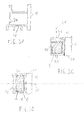
- Fig. 11 shows a transparent view of an, in use lower, part 52A of the first leg 7A.
- the other legs 7B, 7C, 7D can have a similar lower part.
- Fig. 11 shows the first foot 50A and also shows a first attachment section 54.1.
- Fig. 11 further shows an, in use lower, part of a main part 60A of the first leg 7A.
- the other legs preferably have a similar main part.
- the main part of the first leg is preferably hollow.
- the main part 60A of the first leg is formed as a rectangular tubular section.
- the first attachment section 54.1 is slid into the hollow main part 60A of the first leg 7A.
- Fig. 12 also shows the first attachment section 54.1. More in general, the first attachment section 54.1 may be provided with recesses. The recesses can extend in different directions.
- a first recess 56A or a plurality of first recesses 56A may extend, for example, in a length direction 58A of the first attachment section 54.1.
- a second recess 56B or a plurality of second recesses 56B may extend, for example, in a transverse direction 58B of the first attachment section 54.1.
- the transverse direction can be transverse to the length direction.
- a length L of the first attachment section 54.1 can be in a range of 5 centimeters to 50 centimeters.
- An attachment section longer than about 5 centimeters is relatively light and creates the possibility of achieving an attachment of an acceptable strength.
- An attachment section shorter than 50 centimeters has an acceptable weight and creates the possibility of achieving an attachment of a relatively high strength.
- the length L may be, for example, approximately equal to 18 centimeters. However, the length L can also be outside the range mentioned.
- the first attachment section may further be provided with first slots 57A and/or second slots 57B. These first and/or second slots can extend in the length direction 58A of the first attachment section 54.1.
- the first and/or second recesses 56A, 56B are preferably provided with thread. This allows screws 62 to be screwed through recesses in the first leg (not visible) into the second recesses of the first attachment section 54.1. Also, similarly, screws (not visible) can be screwed through recesses in the first foot (not visible) into the first recesses 56A. With the aid of the screws 62 and the attachment section with the first and second recesses 56A, 56B, the first foot 50A can be detachably connected with the main part of the first leg 7A. Alternatively, the first foot part and the first attachment section can be replaced with a plastic cap which closes off the tubular section of the main part 60A of the first leg 7A from below. With the first foot 50A, however, a better support is obtainable than with such a plastic cap.
- the supporting part 6 in the sixth embodiment is further provided with the framework 5 which comprises four support elements in the form of horizontal girders, viz., the first horizontal girder 5A, the second horizontal girder 5B, the third horizontal girder 5C, and the fourth horizontal girder 5D.
- the horizontal girders can form the first and the second support element.
- the first support element may be formed, for example, by the second girder 5B
- the second support element may be formed, for example, by the fourth girder 5D.
- the horizontal girders 5A, 5B, 5C, 5D are mutually connected with the aid of coupling pieces (not visible in Fig 10 , but shown in Figs. 13 , 14 , and 15 with reference numerals 78.1 and 78.2). With the aid of these coupling pieces, also the legs 7A, 7B, 7C, 7D can be attached to the framework 5.
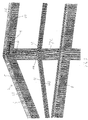
- Fig. 13 shows a transparent top plan view of a first detail 70 of Fig. 10 .
- Fig. 13 shows the third horizontal girder 5C, the fourth horizontal girder 5D, and the fourth leg 7D.
- Fig. 13 further shows a second attachment section 54.2, a third attachment section 54.3, and a fourth attachment section 54.4 which are similar to the first attachment section 54.1 as depicted in Fig. 12 .
- the second attachment section 54.2 in this example is situated substantially in an, in use upper, part of the fourth leg 7D.
- the fourth leg 7D just like the other legs, may be provided with a cover 72 which is connected with cover screws 74 to the second attachment section 54.2.
- Fig. 13 further shows that in this example the third attachment section 54.3 is situated substantially in the third horizontal girder 5C, and that the fourth attachment section 54.4 is situated substantially in the fourth horizontal girder 5D.
- the second, third, and fourth attachment section may be connected with the fourth leg 7D, the third girder 5C, and the fourth girder 5D, respectively, via the screws 62.
- the screws 62 can be screwed through recesses (not visible) in the fourth leg 7D, the third girder 5C, and the fourth girder 5D into the second recesses 56B of the second, third, and fourth attachment sections, respectively, similarly to the screws 62 screwed into the second recesses 56B of the first attachment section 54.1 as described with reference to Fig. 11 .
- the second, third and fourth attachment section 54.2, 54.3, and 54.4 may be comprised by a first coupling piece 78.1 by which the fourth leg 7D, the third girder 5C, and the fourth girder 5D are mutually interconnected.
- the second, third, and fourth attachment section may be mutually interconnected and extend in this example in mutually perpendicular directions.
- Fig. 14 shows an example in which the second, the third, and the fourth attachment section 54.2, 54.3, and 54.4 are mutually interconnected with screws 76.
- the screws 76 that are visible in Fig. 14 extend through third recesses (not visible) in the second attachment section and into the first recesses 56A of the fourth attachment section 54.4.
- the second, third and fourth attachment section can be part of the first coupling piece 78.1.
- the fifth attachment section 54.5 is absent in the example of Fig. 13 .
- Fig. 15 shows a transparent view of a second detail 71 indicated in Fig. 10 .
- Fig. 15 shows a second coupling piece 78.2 which is built up analogously to the first coupling piece 78.1, and shows also a sixth attachment section 54.6.
- the sixth attachment section is received in the first leg 7A and is attached thereto.
- Fig. 15 shows also a seventh attachment section 54.7.
- the seventh attachment section 54.7 is received in the first girder 5A and is attached thereto with the aid of the screws 62.
- Fig. 15 shows further an eighth attachment section 54.8.
- the eighth attachment section 54.8 is received in the fourth girder 5D and is attached thereto with the aid of the screws 62.
- the supporting part 6 is provided with at least one attachment section, viz., the first, second, third, and fourth, sixth, seventh, and eighth attachment section.
- the supporting part of the sun protection device 2 in the sixth embodiment has a first corner point 84A, a second corner point 84B, a third corner point 84C, and a fourth corner point 84D ( Fig. 10 ), and that the first coupling piece 78.1 is near the fourth corner point 84D and that the second coupling piece 78.2 is near the first corner point 84A.
- each corner point there may be one of the coupling pieces.
- first support element for example, the second girder 5B
- second support element for example, the fourth girder 5D
- other elements such as the first girder 5A and the third girder 5C
- the coupling pieces such as the first and second coupling piece 78.1 and 78.2.
- FIG. 16A and 16B show a third coupling piece 78.3 where a ninth and a tenth attachment section 54.9 and 54.10 of the third coupling piece are angle-adjustably connected with each other.
- the ninth and tenth attachment section are similar to the first attachment section as shown in Fig. 12 .
- the third coupling piece 78.3 is provided with outer coupling plates 80A and inner coupling plates 80B.
- the inner coupling plates can be inserted into the second slots 57B of the ninth attachment section.
- the outer coupling plates can be inserted into the first slots 57A of the tenth attachment section.
- the coupling plates 80A,B may be provided with curved slots 82, in which coupling bolts 84 may be present. By tightening the coupling bolts 84, a set angle between the ninth and the tenth attachment section can be fixed.
- Fig. 17 shows a longitudinal cross section of the sun protection device 2 in the sixth embodiment.
- the plane of the cross section passes through the third attachment section 54.3 and the seventh attachment section 54.7, parallel with the legs and the fourth girder 50D.
- Fig. 17 shows the first leg 7A, the fourth leg 7D, the first foot 50A, and the fourth foot 50D.
- Fig. 17 further shows the fourth girder 5D of the framework 5.
- the screen 8 in this example can be slid in and out with the aid of the screen roll 83.
- the screen roll 83 can be part of a winding and unwinding mechanism with the aid of which the screen 8 can be slid in and out.
- the third attachment section 54.3 may be provided with an opening 88. This opening is not present in the first attachment section 54.1. Via the opening 88 the flexible element 16 can be led to the roll of the windup means 18.
- Fig. 17 also shows the windup means 18 and the flexible element 16.
- the flexible element 16 is formed by a flexible sun protection cloth 85.
- the sun protection cloth is connected with the sun blocking part 4.
- the attachment point 15C is along an edge of the sun blocking part, such that the flexible sun protection cloth extends over a first width B 1 which is approximately equal to a second width B 2 of the sun blocking part 4.
- the first width B 1 and the second width B 2 are, for example, approximately equal to a length of the first and the third girder.
- Fig. 18 shows the sun protection device in a seventh embodiment according to the invention.
- the sun protection device 2 is attached to the wall 11.
- the supporting part 6 is adapted for such an attachment.
- the supporting part 6 may be provided with an eleventh and a twelfth attachment section 54.11 and 54.12.
- the eleventh and twelfth attachment section are similar to the first attachment section and may be provided with a mounting plate 90.
- the mounting plate may be connected to the eleventh and twelfth attachment section by means of screws that may be screwed into the first recesses 56A.
- the mounting plates 90 may be provided with the first holes 9E suitable for inserting bolts therethrough. With these bolts the supporting part can then be connected to the wall 11.
- Fig. 18 shows further the attachment point 15C that is along the edge of the sun blocking part 4, such that the flexible sun protection cloth extends over the first width B 1 of the sun protection cloth 85 which is approximately equal to the second width B 2 of the sun blocking part 4 and the screen 8.
- the sun blocking part 4 is connected to the framework 5 of the supporting part 6 so as to be tiltable in the plane 32 which is substantially vertically oriented in use.
- a vertical tilt orientation may be supplemented with, and/or replaced by, a horizontal tilt orientation.
- the sun blocking part may be connected to the supporting part so as to be tiltable in a plane which is substantially horizontally oriented in use.
- the sun protection device 2 in the second, third and fourth embodiment may be provided with the first leg 7A, the second leg 7B, the third leg 7C, and the fourth leg 7D.
- the sun protection device 2 may be provided with only three legs, viz., the first leg 7A, the second leg 7B and the third leg 7C.
- the supporting part may be provided with a guide for the sun blocking part, while the positioning means are also adapted for translating the sun blocking part over the guide for the sun blocking part.
- the positioning means may then be configured for translating the sun blocking part along the guide for the sun blocking part during tilting of the sun blocking part. The combination of translation and tilting further enlarges the possibilities of adjusting the position of the sun blocking part to a position of the sun.
- the sun protection device and/or the positioning means are configured for, at will of the user, tilting the sun blocking part from an untilted situation in one of at least two different directions.
Landscapes
- Engineering & Computer Science (AREA)
- Architecture (AREA)
- Structural Engineering (AREA)
- Civil Engineering (AREA)
- Building Awnings And Sunshades (AREA)
- Tents Or Canopies (AREA)
- Other Air-Conditioning Systems (AREA)
- Refuge Islands, Traffic Blockers, Or Guard Fence (AREA)
- Electric Cable Arrangement Between Relatively Moving Parts (AREA)
Priority Applications (1)
| Application Number | Priority Date | Filing Date | Title |
|---|---|---|---|
| PL10192107T PL2336450T3 (pl) | 2009-11-23 | 2010-11-22 | Osłona przeciwsłoneczna i zastosowanie osłony przeciwsłonecznej |
Applications Claiming Priority (2)
| Application Number | Priority Date | Filing Date | Title |
|---|---|---|---|
| NL2003850 | 2009-11-23 | ||
| NL2004091A NL2004091C2 (nl) | 2009-11-23 | 2010-01-14 | Zonwering en gebruik van een zonwering. |
Publications (3)
| Publication Number | Publication Date |
|---|---|
| EP2336450A2 true EP2336450A2 (fr) | 2011-06-22 |
| EP2336450A3 EP2336450A3 (fr) | 2014-03-12 |
| EP2336450B1 EP2336450B1 (fr) | 2016-01-13 |
Family
ID=43856229
Family Applications (1)
| Application Number | Title | Priority Date | Filing Date |
|---|---|---|---|
| EP10192107.0A Active EP2336450B1 (fr) | 2009-11-23 | 2010-11-22 | Protection contre le soleil et l'utilisation d'une protection solaire |
Country Status (5)
| Country | Link |
|---|---|
| EP (1) | EP2336450B1 (fr) |
| DK (1) | DK2336450T3 (fr) |
| ES (1) | ES2566375T3 (fr) |
| NL (1) | NL2004091C2 (fr) |
| PL (1) | PL2336450T3 (fr) |
Cited By (2)
| Publication number | Priority date | Publication date | Assignee | Title |
|---|---|---|---|---|
| EP3054063A1 (fr) * | 2015-02-06 | 2016-08-10 | Weinor GmbH & Co. KG | Marquise comprenant des rails de guidage abaissables |
| DE102015108589A1 (de) | 2015-06-01 | 2016-12-01 | Leiner Gmbh | Sonnen- und Regenschutzeinrichtung |
Families Citing this family (2)
| Publication number | Priority date | Publication date | Assignee | Title |
|---|---|---|---|---|
| CN108756391B (zh) * | 2018-08-14 | 2020-10-09 | 武汉轻工大学 | 一种立体车库出入系统以及立体车库 |
| DE102022000079A1 (de) * | 2022-01-05 | 2023-07-06 | Truma Gerätetechnik GmbH & Co. KG | Markise sowie Fahrzeug mit Markise |
Family Cites Families (1)
| Publication number | Priority date | Publication date | Assignee | Title |
|---|---|---|---|---|
| DE9410724U1 (de) * | 1994-07-02 | 1994-09-15 | Losberger Sonnenschutz GmbH + Co, 74078 Heilbronn | Ausstellbare Beschattungsanlage |
-
2010
- 2010-01-14 NL NL2004091A patent/NL2004091C2/nl active
- 2010-11-22 DK DK10192107.0T patent/DK2336450T3/en active
- 2010-11-22 PL PL10192107T patent/PL2336450T3/pl unknown
- 2010-11-22 EP EP10192107.0A patent/EP2336450B1/fr active Active
- 2010-11-22 ES ES10192107.0T patent/ES2566375T3/es active Active
Non-Patent Citations (1)
| Title |
|---|
| None |
Cited By (7)
| Publication number | Priority date | Publication date | Assignee | Title |
|---|---|---|---|---|
| EP3054063A1 (fr) * | 2015-02-06 | 2016-08-10 | Weinor GmbH & Co. KG | Marquise comprenant des rails de guidage abaissables |
| DE102015001416A1 (de) * | 2015-02-06 | 2016-08-11 | Weinor Gmbh & Co. Kg | Markise mit absenkbaren Führungsschienen |
| EP3054063B1 (fr) | 2015-02-06 | 2017-05-10 | Weinor GmbH & Co. KG | Marquise comprenant des rails de guidage abaissables |
| DE102015108589A1 (de) | 2015-06-01 | 2016-12-01 | Leiner Gmbh | Sonnen- und Regenschutzeinrichtung |
| EP3101197A1 (fr) | 2015-06-01 | 2016-12-07 | Leiner GmbH | Dispositif de protection contre la pluie ou le soleil |
| DE102015108589B4 (de) | 2015-06-01 | 2017-02-09 | Leiner Gmbh | Sonnen- und Regenschutzeinrichtung |
| DE202016008501U1 (de) | 2015-06-01 | 2018-03-08 | Leiner Gmbh | Sonnen- und Regenschutzeinrichtung |
Also Published As
| Publication number | Publication date |
|---|---|
| EP2336450A3 (fr) | 2014-03-12 |
| NL2004091C2 (nl) | 2011-05-24 |
| EP2336450B1 (fr) | 2016-01-13 |
| PL2336450T3 (pl) | 2016-08-31 |
| DK2336450T3 (en) | 2016-04-04 |
| ES2566375T3 (es) | 2016-04-12 |
Similar Documents
| Publication | Publication Date | Title |
|---|---|---|
| US20120211179A1 (en) | Covering System | |
| JP3766440B2 (ja) | 特に水泳プール用の、可動カバー装置 | |
| US8051866B2 (en) | Covering system | |
| EP2336450B1 (fr) | Protection contre le soleil et l'utilisation d'une protection solaire | |
| CN111034491A (zh) | 一种绿色建筑的屋顶绿化系统 | |
| KR101281774B1 (ko) | 커버링 시스템 | |
| US20110030750A1 (en) | Portable shelter having resiliently supported awning | |
| JP5150611B2 (ja) | 仮設構造物 | |
| US20170030083A1 (en) | Privacy and weather protection barrier | |
| JP3375897B2 (ja) | オーニング装置 | |
| JP2011058170A (ja) | 伸縮テント屋根装置 | |
| KR102720367B1 (ko) | 개선된 브라켓 구조를 포함하는 어닝 장치 | |
| GB2446864A (en) | Awning with drain | |
| WO2020148717A1 (fr) | Revêtement de patio résistant aux intempéries à drainage de liquide transversal | |
| US20060150529A1 (en) | Weather protection system | |
| KR102720368B1 (ko) | 개선된 프레임 구조를 포함하는 어닝 장치 | |
| KR102946300B1 (ko) | 경사기둥과 무게추를 이용한 웨이브 어닝용 설치 구조물 | |
| CN213418669U (zh) | 一种具有防潮功能的帐篷 | |
| WO2021133182A1 (fr) | Store d'auvent mobile destiné à protéger du soleil | |
| WO2024047619A1 (fr) | Dispositif de store banne | |
| JP2008231680A (ja) | 遮蔽装置 | |
| IL280681A (en) | Awning device | |
| ITVR20090163A1 (it) | Tensostruttura. | |
| KR20170004337A (ko) | 차양용 어닝 | |
| JP2007270495A (ja) | 屋根付き簡易建築物 |
Legal Events
| Date | Code | Title | Description |
|---|---|---|---|
| PUAI | Public reference made under article 153(3) epc to a published international application that has entered the european phase |
Free format text: ORIGINAL CODE: 0009012 |
|
| AK | Designated contracting states |
Kind code of ref document: A2 Designated state(s): AL AT BE BG CH CY CZ DE DK EE ES FI FR GB GR HR HU IE IS IT LI LT LU LV MC MK MT NL NO PL PT RO RS SE SI SK SM TR |
|
| AX | Request for extension of the european patent |
Extension state: BA ME |
|
| PUAL | Search report despatched |
Free format text: ORIGINAL CODE: 0009013 |
|
| AK | Designated contracting states |
Kind code of ref document: A3 Designated state(s): AL AT BE BG CH CY CZ DE DK EE ES FI FR GB GR HR HU IE IS IT LI LT LU LV MC MK MT NL NO PL PT RO RS SE SI SK SM TR |
|
| AX | Request for extension of the european patent |
Extension state: BA ME |
|
| RIC1 | Information provided on ipc code assigned before grant |
Ipc: E06B 9/92 20060101ALI20140131BHEP Ipc: E04F 10/06 20060101AFI20140131BHEP |
|
| 17P | Request for examination filed |
Effective date: 20140829 |
|
| RBV | Designated contracting states (corrected) |
Designated state(s): AL AT BE BG CH CY CZ DE DK EE ES FI FR GB GR HR HU IE IS IT LI LT LU LV MC MK MT NL NO PL PT RO RS SE SI SK SM TR |
|
| GRAP | Despatch of communication of intention to grant a patent |
Free format text: ORIGINAL CODE: EPIDOSNIGR1 |
|
| INTG | Intention to grant announced |
Effective date: 20150618 |
|
| GRAS | Grant fee paid |
Free format text: ORIGINAL CODE: EPIDOSNIGR3 |
|
| GRAA | (expected) grant |
Free format text: ORIGINAL CODE: 0009210 |
|
| AK | Designated contracting states |
Kind code of ref document: B1 Designated state(s): AL AT BE BG CH CY CZ DE DK EE ES FI FR GB GR HR HU IE IS IT LI LT LU LV MC MK MT NL NO PL PT RO RS SE SI SK SM TR |
|
| REG | Reference to a national code |
Ref country code: GB Ref legal event code: FG4D |
|
| REG | Reference to a national code |
Ref country code: CH Ref legal event code: EP |
|
| REG | Reference to a national code |
Ref country code: IE Ref legal event code: FG4D |
|
| REG | Reference to a national code |
Ref country code: AT Ref legal event code: REF Ref document number: 770630 Country of ref document: AT Kind code of ref document: T Effective date: 20160215 |
|
| REG | Reference to a national code |
Ref country code: DE Ref legal event code: R096 Ref document number: 602010030124 Country of ref document: DE |
|
| REG | Reference to a national code |
Ref country code: DK Ref legal event code: T3 Effective date: 20160331 |
|
| REG | Reference to a national code |
Ref country code: SE Ref legal event code: TRGR |
|
| REG | Reference to a national code |
Ref country code: ES Ref legal event code: FG2A Ref document number: 2566375 Country of ref document: ES Kind code of ref document: T3 Effective date: 20160412 Ref country code: PT Ref legal event code: SC4A Free format text: AVAILABILITY OF NATIONAL TRANSLATION Effective date: 20160329 |
|
| REG | Reference to a national code |
Ref country code: NL Ref legal event code: FP |
|
| REG | Reference to a national code |
Ref country code: LT Ref legal event code: MG4D |
|
| REG | Reference to a national code |
Ref country code: NO Ref legal event code: T2 Effective date: 20160113 |
|
| PG25 | Lapsed in a contracting state [announced via postgrant information from national office to epo] |
Ref country code: HR Free format text: LAPSE BECAUSE OF FAILURE TO SUBMIT A TRANSLATION OF THE DESCRIPTION OR TO PAY THE FEE WITHIN THE PRESCRIBED TIME-LIMIT Effective date: 20160113 Ref country code: GR Free format text: LAPSE BECAUSE OF FAILURE TO SUBMIT A TRANSLATION OF THE DESCRIPTION OR TO PAY THE FEE WITHIN THE PRESCRIBED TIME-LIMIT Effective date: 20160414 |
|
| PG25 | Lapsed in a contracting state [announced via postgrant information from national office to epo] |
Ref country code: IS Free format text: LAPSE BECAUSE OF FAILURE TO SUBMIT A TRANSLATION OF THE DESCRIPTION OR TO PAY THE FEE WITHIN THE PRESCRIBED TIME-LIMIT Effective date: 20160513 Ref country code: LT Free format text: LAPSE BECAUSE OF FAILURE TO SUBMIT A TRANSLATION OF THE DESCRIPTION OR TO PAY THE FEE WITHIN THE PRESCRIBED TIME-LIMIT Effective date: 20160113 Ref country code: RS Free format text: LAPSE BECAUSE OF FAILURE TO SUBMIT A TRANSLATION OF THE DESCRIPTION OR TO PAY THE FEE WITHIN THE PRESCRIBED TIME-LIMIT Effective date: 20160113 Ref country code: LV Free format text: LAPSE BECAUSE OF FAILURE TO SUBMIT A TRANSLATION OF THE DESCRIPTION OR TO PAY THE FEE WITHIN THE PRESCRIBED TIME-LIMIT Effective date: 20160113 |
|
| REG | Reference to a national code |
Ref country code: DE Ref legal event code: R097 Ref document number: 602010030124 Country of ref document: DE |
|
| PG25 | Lapsed in a contracting state [announced via postgrant information from national office to epo] |
Ref country code: EE Free format text: LAPSE BECAUSE OF FAILURE TO SUBMIT A TRANSLATION OF THE DESCRIPTION OR TO PAY THE FEE WITHIN THE PRESCRIBED TIME-LIMIT Effective date: 20160113 |
|
| PLBE | No opposition filed within time limit |
Free format text: ORIGINAL CODE: 0009261 |
|
| REG | Reference to a national code |
Ref country code: FR Ref legal event code: PLFP Year of fee payment: 7 |
|
| STAA | Information on the status of an ep patent application or granted ep patent |
Free format text: STATUS: NO OPPOSITION FILED WITHIN TIME LIMIT |
|
| PG25 | Lapsed in a contracting state [announced via postgrant information from national office to epo] |
Ref country code: SK Free format text: LAPSE BECAUSE OF FAILURE TO SUBMIT A TRANSLATION OF THE DESCRIPTION OR TO PAY THE FEE WITHIN THE PRESCRIBED TIME-LIMIT Effective date: 20160113 Ref country code: RO Free format text: LAPSE BECAUSE OF FAILURE TO SUBMIT A TRANSLATION OF THE DESCRIPTION OR TO PAY THE FEE WITHIN THE PRESCRIBED TIME-LIMIT Effective date: 20160113 Ref country code: SM Free format text: LAPSE BECAUSE OF FAILURE TO SUBMIT A TRANSLATION OF THE DESCRIPTION OR TO PAY THE FEE WITHIN THE PRESCRIBED TIME-LIMIT Effective date: 20160113 |
|
| 26N | No opposition filed |
Effective date: 20161014 |
|
| PG25 | Lapsed in a contracting state [announced via postgrant information from national office to epo] |
Ref country code: BG Free format text: LAPSE BECAUSE OF FAILURE TO SUBMIT A TRANSLATION OF THE DESCRIPTION OR TO PAY THE FEE WITHIN THE PRESCRIBED TIME-LIMIT Effective date: 20160413 Ref country code: SI Free format text: LAPSE BECAUSE OF FAILURE TO SUBMIT A TRANSLATION OF THE DESCRIPTION OR TO PAY THE FEE WITHIN THE PRESCRIBED TIME-LIMIT Effective date: 20160113 |
|
| REG | Reference to a national code |
Ref country code: AT Ref legal event code: UEP Ref document number: 770630 Country of ref document: AT Kind code of ref document: T Effective date: 20160113 |
|
| REG | Reference to a national code |
Ref country code: FR Ref legal event code: PLFP Year of fee payment: 8 |
|
| PG25 | Lapsed in a contracting state [announced via postgrant information from national office to epo] |
Ref country code: HU Free format text: LAPSE BECAUSE OF FAILURE TO SUBMIT A TRANSLATION OF THE DESCRIPTION OR TO PAY THE FEE WITHIN THE PRESCRIBED TIME-LIMIT; INVALID AB INITIO Effective date: 20101122 Ref country code: CY Free format text: LAPSE BECAUSE OF FAILURE TO SUBMIT A TRANSLATION OF THE DESCRIPTION OR TO PAY THE FEE WITHIN THE PRESCRIBED TIME-LIMIT Effective date: 20160113 |
|
| PG25 | Lapsed in a contracting state [announced via postgrant information from national office to epo] |
Ref country code: MK Free format text: LAPSE BECAUSE OF FAILURE TO SUBMIT A TRANSLATION OF THE DESCRIPTION OR TO PAY THE FEE WITHIN THE PRESCRIBED TIME-LIMIT Effective date: 20160113 |
|
| PG25 | Lapsed in a contracting state [announced via postgrant information from national office to epo] |
Ref country code: MT Free format text: LAPSE BECAUSE OF NON-PAYMENT OF DUE FEES Effective date: 20161122 |
|
| PG25 | Lapsed in a contracting state [announced via postgrant information from national office to epo] |
Ref country code: AL Free format text: LAPSE BECAUSE OF FAILURE TO SUBMIT A TRANSLATION OF THE DESCRIPTION OR TO PAY THE FEE WITHIN THE PRESCRIBED TIME-LIMIT Effective date: 20160113 |
|
| REG | Reference to a national code |
Ref country code: CH Ref legal event code: U11 Free format text: ST27 STATUS EVENT CODE: U-0-0-U10-U11 (AS PROVIDED BY THE NATIONAL OFFICE) Effective date: 20251201 |
|
| PGFP | Annual fee paid to national office [announced via postgrant information from national office to epo] |
Ref country code: PT Payment date: 20251113 Year of fee payment: 16 |
|
| PGFP | Annual fee paid to national office [announced via postgrant information from national office to epo] |
Ref country code: NL Payment date: 20251119 Year of fee payment: 16 Ref country code: LU Payment date: 20251119 Year of fee payment: 16 |
|
| PGFP | Annual fee paid to national office [announced via postgrant information from national office to epo] |
Ref country code: DE Payment date: 20251119 Year of fee payment: 16 |
|
| PGFP | Annual fee paid to national office [announced via postgrant information from national office to epo] |
Ref country code: GB Payment date: 20251121 Year of fee payment: 16 |
|
| PGFP | Annual fee paid to national office [announced via postgrant information from national office to epo] |
Ref country code: NO Payment date: 20251125 Year of fee payment: 16 Ref country code: MC Payment date: 20251121 Year of fee payment: 16 |
|
| PGFP | Annual fee paid to national office [announced via postgrant information from national office to epo] |
Ref country code: AT Payment date: 20251120 Year of fee payment: 16 |
|
| PGFP | Annual fee paid to national office [announced via postgrant information from national office to epo] |
Ref country code: IT Payment date: 20251125 Year of fee payment: 16 Ref country code: FI Payment date: 20251125 Year of fee payment: 16 Ref country code: DK Payment date: 20251125 Year of fee payment: 16 |
|
| PGFP | Annual fee paid to national office [announced via postgrant information from national office to epo] |
Ref country code: FR Payment date: 20251124 Year of fee payment: 16 |
|
| PGFP | Annual fee paid to national office [announced via postgrant information from national office to epo] |
Ref country code: TR Payment date: 20251117 Year of fee payment: 16 Ref country code: BE Payment date: 20251119 Year of fee payment: 16 |
|
| PGFP | Annual fee paid to national office [announced via postgrant information from national office to epo] |
Ref country code: SE Payment date: 20251119 Year of fee payment: 16 Ref country code: CH Payment date: 20251201 Year of fee payment: 16 |
|
| PGFP | Annual fee paid to national office [announced via postgrant information from national office to epo] |
Ref country code: IE Payment date: 20251121 Year of fee payment: 16 Ref country code: CZ Payment date: 20251119 Year of fee payment: 16 |
|
| PGFP | Annual fee paid to national office [announced via postgrant information from national office to epo] |
Ref country code: PL Payment date: 20251114 Year of fee payment: 16 |
|
| PGFP | Annual fee paid to national office [announced via postgrant information from national office to epo] |
Ref country code: ES Payment date: 20251229 Year of fee payment: 16 |